
Development of Composite Hydraulic Actuators: A Review
by
 , , , , and
Marek Lubecki
1,
Michał Stosiak
1,
Paulius Skačkauskas
2,*,
Mykola Karpenko
2,
Adam Deptuła
3 and
and
Kamil Urbanowicz
4 1
Faculty of Mechanical Engineering, Wrocław University of Science and Technology, 7/9 Łukasiewicza St., 50-371 Wrocław, Poland
2
Faculty of Transport Engineering, Vilnius Gediminas Technical University, Saulėtekio al. 11, LT-10223 Vilnius, Lithuania
3
Faculty of Production Engineering and Logistics, Opole University of Technology, 76 Prószkowska St., 45-758 Opole, Poland
4
Faculty of Mechanical Engineering and Mechatronics, West Pomeranian University of Technology, 70-310 Szczecin, Poland
*
Author to whom correspondence should be addressed.
Actuators 2022, 11(12), 365; https://doi.org/10.3390/act11120365
Submission received: 26 October 2022
/
Revised: 22 November 2022
/
Accepted: 5 December 2022
/
Published: 6 December 2022
(This article belongs to the Special Issue 10th Anniversary of Actuators)
Abstract
:With the development of engineering materials, as well as the growing requirements for weight reduction and the reduction of energy consumption by mechanical systems, attempts have been made to utilize composite materials in the design of hydraulic cylinders. In many cases, the reduction in the weight of the actuators may lead to a reduction in the values of bending moments acting on the booms of working machines, as well as leading to a reduction in the power demand in drive systems. The use of composite materials can also increase the reliability of cylinders in corrosive environments and places with strong electromagnetic fields. This paper presents the development of hydraulic actuators made of composite materials, presenting both the achievements of research centers and commercial companies. The main research and engineering problems are presented along with the methods of solving them resulting from the literature available. The directions for further research that should be undertaken in order to increase reliability, improve efficiency, and reduce weight are also outlined.
1. Introduction
A hydrostatic drive is one of the most popular types of drives in mechanical engineering. It consists of a pump that converts kinetic energy (most often shaft rotation) into the energy of fluid pressure, a set of valves whose task is to control the flow parameters (flow rate, direction, and pressure), receivers (motors and actuators) converting fluid pressure energy into mechanical energy, and other elements such as hoses or accumulators. The popularity of this type of systems is a result of a number of advantages, such as a high ratio of power transmitted to the mass of the system, the possibility of arranging the elements on the machine, or the possibility of obtaining almost any functional structure as well as the ease of automation [1].
Hydraulic cylinders are actuators whose task is to convert the energy of fluid pressure into the mechanical energy of a reciprocating movement. The fluid acts on the movable element of the actuator (piston or plunger) causing a force directly proportional to the pressure and the area of the element. A double-rod hydraulic cylinder is shown on Figure 1. It consists of a front joint (1), piston rod (2), front-end cap (3), piston (4), barrel (5), rear-end cap (6), and a tail joint (7) [2]. Standard hydraulic cylinders are designed to operate at working pressures up to 25 MPa; versions with higher working pressures are also available on request. Diameter and pitch ranges vary from a few millimeters [3,4] to several meters [5]. Many years of perfecting the design of actuators has allowed a general efficiency close to 100% [6,7] to be obtained.
When choosing a material, the issues of strength, durability, manufacturing technology, and cost must be taken into account [8]. Environmental issues are becoming more and more important, forcing the reduction or elimination of harmful materials, emissions, and the amount of waste produced. Efforts are also being made to design structures in such a way that they consumes as little energy as possible during operation. Weight reduction is a desirable step in this context, as it is usually associated with the increased energy efficiency of the machine [9,10]. Conventional hydraulic cylinders are mostly made of steel or aluminum alloys, and the seals are made of plastics and bronze. The most popular alloys include structural steel S355J2G3 [11], austenitic stainless steel AISI 304, and aluminum alloy Al7075 [12,13].
A composite is a material obtained by combining two or more base materials with (most often) radically different properties. The resulting material has better and (or) new properties compared to the components used separately or resulting from their simple summation. In most cases, one of the materials takes the role of a matrix (continuous, bonding medium), while the rest becomes the filler (reinforcement) [14,15].
Among the fibrous composites (in which the reinforcement is realized by fibers), we can distinguish two main types: those reinforced with short fibers and those reinforced with continuous fibers. Fibers (most often glass, carbon, or aramid) are characterized by a high modulus of elasticity along their axis and high tensile strength [16]. There are many types of fibers on the market that differ in terms of parameters and the materials from which they are made and thus also the price.
The second component of the composite material is the matrix, the purpose of which is to bond the reinforcement material and to enable load transfer between the fibers. It can also stop or slow down the propagation of cracks initiated in the reinforcement and protect the fibers from adverse environmental conditions [17]. The most commonly used matrix materials include polyester, vinyl ester, or epoxy resins, as well as thermoplastics (polyethylene, polypropylene, and polyamide).
Year by year, there is growing interest in the use of fiber-reinforced composite materials. This is due to their high strength, low weight, and corrosion resistance. There are many methods of manufacturing fiber-reinforced polymeric composite materials, such as lamination (hand, spray, vacuum bag), infusion molding, winding, weaving, and pultrusion. In the production of high-pressure cylinders and tanks, mainly winding and weaving methods have been used [18].
2. Design and Research Issues
When designing a hydraulic cylinder, it is necessary to take into account the differences resulting from the nature of the composite material. A number of problems that the designer faces during the design process of such an element are presented below.
2.1. Material Anisotropy
The use of fiber-reinforced composites in a load-bearing structure entails the need to take into account the significant anisotropy of such materials. A single unidirectional layer shows high strength and a high Young’s modulus along the fibers, but much lower parameters in the direction perpendicular to the reinforcement fibers. The classical methods of calculating the barrel wall thickness taken from conventional actuator designs cannot be used [19]. Designers must therefore use computational methods developed for multilayer elements, often combining anisotropic composite layers with isotropic steel or aluminum.
2.2. Piston–Barrel Interface
It is crucial to ensure the proper frictional cooperation of the piston seal with the inner surface of the barrel. The phenomena occurring at the contact of polymer seals and the steel or aluminum inner layer of a classic cylinder are already well known. Changing the material, however, makes it necessary to describe these phenomena anew. Material and technological solutions are also sought to make the inner layer as resistant to wear as possible and with the lowest possible coefficient of friction [20,21]. One of the solutions is the use of a thin-walled steel pipe (so-called liner) on which a composite overwrap is made.
2.3. Connecting the Barrel with the End Caps
In conventional hydraulic actuators, threaded or tie-rod connections are most often used to connect the barrel with the end caps [22]. While the latter solution is applicable to composite cylinders, cutting threads in the composite material is not advised [23]. Designing an actuator without tie-rods requires an adhesive or form-fit connection. An alternative solution is to cut threads in the liner material.
3. Research Work on the Development of Composite Cylinders
The scientific literature offers various approaches to the issue of designing a hydraulic actuator with a composite barrel.
In as early as 1986, Hashimoto et al. [24] presented an innovative composite hydraulic cylinder with an integrated piston position sensor. They presented a method of connecting composite parts made by winding with steel elements with the use of pins, with which the fiber was wrapped during manufacturing. The advantage of this form-fit connection is the continuity of the fibers and the avoidance of mechanical processing of the composite as well as the elimination of the adhesive connection. This method was tested both statically and with impulse loads. A magnetostrictive piston position sensor was integrated in the actuator barrel. Such a sensor was characterized by high accuracy and repeatability of reading, and the wound barrel structure was well suited to integrating this solution. The described prototype had an internal diameter of 50 mm, a piston rod diameter of 28 mm, a stroke of 500 mm, and a weight of 4.7 kg. This was a 2/3 reduction in the weight of the element compared to a conventional steel actuator. A similar design was presented by Sumali et al. [25]. The sensor consisted of a coil wound up during the manufacturing of the barrel and thus embedded in its wall, and a steel piston rod that also served as the core of the coil. The sliding of the piston rod into the coil changes the position of the core in the coil, which changes the inductance and thus the impedance of the coil. The impedance measurement allowed the position of the actuator piston to be determined. The resulting cylinder had an inside diameter of 38.1 mm, an outside diameter of 44.45 mm, and a stroke of 203.2 mm.
Mantovani et al. [26,27] presented a method of designing a composite cylinder with a steel liner in terms of strength and buckling. The analysis presented by the authors was performed for an actuator with a working pressure of 35 MPa, an internal diameter of 300 mm, and a stroke of 1960 mm. For this purpose, the authors used the solution of the Lame problem modified for anisotropic materials. Design constraints have been adopted to ensure the appropriate immediate strength of the cylinder as well as the appropriately low values of the circumferential deformation of the cylinder and the axial deformation of the liner. Due to the fact that the considered barrel would also transmit axial forces, the authors designed layers in it, in which the fibers would be arranged along the axis of the element. Finally, a modal analysis was carried out, which did not show any significant differences in the natural frequencies between the composite barrel and the reference (steel) one. The designed barrel had a mass of 80 kg compared to 407 kg of the reference barrel, which translates into a weight reduction of approx. 80%.
Ritchie et al. [28] performed the FEM analysis and manufactured and tested the piston and the front cap from a composite material reinforced with carbon fiber. The elements were made using subtractive methods from ready-made pipes, which is not recommended in the case of composite materials. The authors defined the machinability of the composite as medium and the obtained surface quality and dimensional accuracy as low. The conducted corrosion tests as well as the comparison of the weights of both elements showed the superiority of the composite material over steel. The paper does not present the tests of the complete actuator.
Scholz and Kroll [20] considered removing the steel liner from the inside of the barrel and replacing it with a nanocomposite coating with properties ensuring appropriate tribological conditions at the barrel–piston interface. The authors presented methods of calculating stresses in individual composite layers, as well as a method of producing nanocomposite coatings (Figure 2). However, the process of selecting and optimizing the laminate structure is not presented in detail. The manufactured cylinders were tested, the deformation as a function of internal pressure and the abrasive wear of the nanocomposite layer were determined (Figure 3). The prototypes had an internal diameter of 85.5 mm, a barrel length of 250 mm, and a barrel thickness of 2.8 mm. The operating pressure was 35 MPa with a burst pressure of 700 MPa. The authors confirmed the suitability of a selected coating as a sliding material in a cylinder.
Nowak and Schmidt [29,30,31] conducted an in-depth theoretical analysis of composite pipes with a steel liner, deriving analytical formulas allowing the stress distribution to be calculated, taking into account the loads of internal pressure, axial force, and temperature. They also conducted experimental verification with the use of strain gauges and acoustic emission. The analysis was made for barrels with a length of 420 mm, with a liner with an internal diameter of 185 mm, and an external diameter of 193 mm and 204 mm. The thickness of the composite winding ranged from 7 mm to 15 mm. The internal pressure up to 75 MPa was used in the tests. The authors showed that as long as the liner works in the range of elastic deformations, the composite overwrap does not transfer significant loads. However, when the liner is in the range of plastic deformation, the composite provides the structural integrity with the necessary strength.
Various methods of connecting the end caps to the composite barrel were considered by Zhang et al. [32]. The authors proposed a proprietary method called inlaid connection consisting of connecting the front-end cap, liner, and the rear-end cap using a composite overwrap. According to the authors, this ensures a more secure connection of elements, easier service, and more economical use of materials. The paper presents laminate strength calculations assuming a constant winding angle of 63.43° and a laminate thickness of 5 mm. The calculations were carried out for a cylinder with an internal diameter of 50 mm, a piston rod diameter of 28 mm, a stroke of 500 mm, a working pressure of 25 MPa, and a maximum pressure of 37.5 MPa. However, the authors did not take into account the strength of the steel liner, as it was assumed that the entire load would be carried by the composite.
Lightweight hydraulic actuators can also be used in robotics. El Asswad et al. [33,34] designed and manufactured a prototype, and they subjected a hydraulic cylinder with a composite barrel to bench tests and intended for it to be used as the drive of a humanoid robot. The process of barrel design was shown taking into account the material anisotropy using the Tsai–Hill criterion. The genetic algorithm was used to find the optimal geometric dimensions of individual actuator elements while minimizing the final mass of the assembly. Two prototypes of actuators were made one with tie-rods and the other, where the end caps were connected to the barrel using adhesive. The friction coefficient was determined, which turned out to be quite high (0.61), which was related to the properties of the composite surface. The presented design had an internal diameter of 25 mm, a piston rod diameter of 12 mm, and a stroke of 110 mm. It was tested at a supply pressure of 4 MPa. It is worth noting the use of a piston was made possible by 3D printing.
In a series of publications, Solazzi and colleagues presented the design process of a composite hydraulic cylinder along with its implementation and testing. Basic strength calculations of the barrel, front, and end caps, as well as the piston rod, were presented. The cylinder calculations took into account the material anisotropy, and 0°, ±45°, and 90° were assumed as the allowed fiber angles [35]. The criterions of Tresca and Huber–Mises were used as the strength criteria. The authors provided several variants of the individual elements (made of steel, aluminum alloy, aluminum alloy, and an epoxy–carbon composite) with a weight comparison. A prototype of a barrel, consisting of an inner steel liner and a carbon–epoxy overwrap, manufactured using the filament winding method was also pressure tested. Winding was performed by hand and the element was post-treated to obtain a uniform outside diameter. Next, the authors presented a process of designing a telescopic actuator made of a composite material [36]. The material selection and the basic strength calculations for an isotropic material and also partially for an anisotropic material, as well as finite element analysis, were presented. Particular emphasis was placed on preventing buckling of the element. Once again, the Huber–Mises hypothesis, commonly used for metallic materials, was used to assess the strength of the composite material. The authors took into account the difficulties in joining the actuator parts resulting from the fact that they were made of different materials and proposed the adhesive joint as the best suited. The next paper presents strength calculations for the cylinder, taking into account its layering (the presence of an internal aluminum liner and an external composite reinforcement) [37]. The Huber–Mises hypothesis was used to assess the strength. Both the end caps and the liner were made of aluminum alloy and then joined together by welding (Figure 4). A composite reinforcement made of carbon fabric and epoxy resin was placed on the prepared element by means of hand laminating with the help of a vacuum bag (Figure 5). Additionally, the paper presents a piston rod made of a composite material with a method of connecting an aluminum piston and a front joint with a composite piston rod by means of a form fit. The last part of the article presents experimental tests of a finished actuator. The tested actuator had a liner with an internal diameter of 50 mm and a wall thickness of 3 mm with a 4 mm composite overwrap. The piston rod diameter was 40 mm and the stroke diameter was 500 mm. Next, the problem of stress variability in a cylinder consisting of an aluminum liner reinforced with an epoxy–glass laminate was described [38]. The variability of the stress will result from the variability of operating parameters, such as internal pressure, as well as from the geometrical variability (manufacturing inaccuracies) and material properties. The coefficient of variation was introduced, which is a measure of the spread of actual stress values around the mean value, which increased with the increase in the input parameters tolerance. Solazzi and Buffoli in their paper from 2021 [39] described the design process of a composite cylinder taking into account the action of fatigue loads. A membrane model of the material modified with anisotropy was adopted for strength calculations. The Tsai–Hill criterion was adopted as the failure hypothesis, which is better than the previously used criteria of Tresca or Huber–Mises to assess the strength of composites. The fatigue strength was estimated using from available S-N curves for composite materials.
Praveen Kumar and Lee [40] developed hybrid piston rods combining a steel core with an external composite reinforcement. They performed buckling analysis using the finite element method as well as experimental tests for a wide range of elements with a length of 650 mm and outer diameters ranging from 7.5 mm to 30 mm. The CFRP content ranged from 0% for solid steel rods to 100% for all-composite designs. It has been shown that the increase in the proportion of composites in the element increases its resistance to buckling. This was also influenced by the angle of the fibers, where the reinforcement at 0° worked best; however, it should not appear alone, but rather in combination with the layers of ±45° and 90°. The authors suggest that the use of hybrid piston rods will allow for a significant reduction in the mass of the cylinder without sacrificing its buckling resistance, which in the case of these elements is one of the key parameters taken into account in the selection process.
A different approach to multi-material composite elements was presented by Siegfarth et al. [41]. The authors proposed two designs of a monolithic piston integrated with the piston rod and seal manufactured using the MMAM (multi material additive manufacturing) method. The components shown had a piston diameter of 3.6 mm, a seal outer diameter of approximately 4.5 mm, and a piston rod diameter of 2.5 mm. It is worth noting that the entire element was made together with sealing in one process using PolyJet 3D printing technology (Figure 6). The paper presents experimental studies of water absorption, friction, and wear. Despite achieving lower operational parameters than conventional designs, the authors indicate a high potential for the further development of the presented solutions.
The complete design, manufacturing, and testing process was presented by Li et al. [2]. The authors described a double-rod actuator with a metallic liner reinforced with a CFRP overwrap (Figure 7). The end caps were connected to the barrel liner with screws, which ensured the possibility of servicing. The paper includes a liner material selection process and FEM calculations for a multi-material barrel, as well as a description of the manufacturing process. The prototype consisted of an aluminum alloy liner on which composite layers were applied by means of filament winding and hand laminating, and it had an internal diameter of 75 mm, a piston rod diameter of 30 mm, and a barrel length of 80 mm. The design pressure was 21 MPa with a maximum pressure of 31.5 MPa. The designed laminate had layers arranged at an angle of 0 and 90 to the axis of the cylinder. The FEM calculations did not use the strength hypotheses specific to composite materials, and the stresses were presented according to the Huber–von Mises hypothesis. The authors performed leakage and friction tests, as well as deformation measurements. The proposed design approach managed to reduce the barrel weight by more than 56% while maintaining the current operating parameters.
Coskun and Sahin presented a novel approach to the design of a composite hydraulic cylinder [42]. This solution was inspired by composite pressure vessels, in which the composite winding is made not only on the cylindrical part, but also on the domes (Figure 8). In the case of an actuator, this solves the issue of connecting the end caps to the barrel. The authors focused on the computational part in which they optimized the structure of the barrel material using FEM and steepest ascent methods. The described solution allows the mass of the element to be significantly reduced and the problem of connecting the barrel with the end caps to be eliminated. On the other hand, in the event of failure, it significantly hinders the servicing of such an actuator.
Lubecki et al. conducted tribological tests using the ball on disk method [43,44] and adhesive tests using the pull-off method [45,46] of potential materials for the inner coating of the composite barrel. The aim was to replace the steel liner used so far in most designs. From these tests, it was concluded that the best material was thermosetting polyurethane, which achieved the best adhesion results to the composite substrate, as well as a low coefficient of friction and low wear. The team also conducted thermomechanical tests on PET plastic confirming its suitability for the end caps of a hydraulic cylinder [47]. The authors presented the FEM analysis taking into account the non-linearity of the material and experimental validation on the completed end cap prototype (Figure 9). The presented end cap was intended for use in a cylinder with an internal diameter of 40 mm. Prototype tests were carried out at an internal pressure of 25 MPa.
The next paper presents theoretical calculations and an experimental analysis of the deformation of a barrel of a tie-rod hydraulic cylinder [48]. The authors indicated that the load distribution in the real cylinder differs from that usually assumed in theoretical calculations. An example of calculating the strength of a composite cylinder using the classical laminate theory method was also presented. The authors pointed out that during the strength calculations of the composite barrel, it is crucial to correctly identify the loads. Even small deviations from the actual distribution may result, in the case of a strongly anisotropic material, in obtaining incorrect values of the stresses and strains in the layers.
4. Patents
Searching the patent databases, one can find a number of solutions of hydraulic and pneumatic actuators using composite materials in their design. Patent US4685384A [49] presents a hydraulic composite actuator, the barrel of which would consist of an internal liner ensuring appropriate conditions for cooperation with the piston and an external composite reinforcement. The integrity of the element is ensured by an additional longitudinal overwrap that connects the front cap with a tail joint and is fixed on the supporting ring by means of a form fit and an additional circumferential overwrap (Figure 10).
A different approach is proposed in patent US5415079A [50]. Here, the connection is made by specially shaping both ends of the liner. The helical winding is made in such a way that the turn takes place on the outer parts of the diameter change, which results in a permanent connection between the liner and the composite. End caps are connected to the cylinder by a threaded connection (Figure 11).
Patent US5435868A [51] describes a method of manufacturing composite barrels with internal threads at the ends using the filament winding method (Figure 12). It uses a cylindrical core with threaded inserts (36) placed on it. The barrels (10), with smooth parts (12) and threaded parts (20), (22) are produced by a winding process and separated from each other by distances (58). After the process, the core is pulled from the center and the threaded inserts are unscrewed from the barrels. In this way, the outer thread contour of the inserts is transferred to the inner thread of the composite barrel. The advantage of this method is that it can produce multiple elements on a single core.
Patent US5465647A [52] shows a method of connecting a composite barrel with an end cap (Figure 13) by making a groove (34) inside the barrel (10) cooperating with a barb (38) of the cover (14). In order to increase the stiffness of the connection, after its completion, an expanding ring (42) is used, whose task is to press the skirt (36) of the cover against the inner wall of the barrel. As a rule, such a connection is inseparable.
Another approach to detachably connect the barrel with the end cap was presented in US7240607B2 [53] (Figure 14). The barrel (12) has a groove (28) made on its outer surface (26) in which holes (30) are drilled radially. The groove (28) is designed to receive the split ring (20) also with holes (44). An end cap (16) with tapped holes (40) matching the holes in the ring (44) and barrel (30) is placed inside the cylinder. The connection is made by means of screws (22). The advantages of this solution are the ease of connecting and disconnecting elements using popular tools, the possibility of using pipes available on the market, and improving the load distribution through the use of a ring. Due to the machining of the composite cylinder, the immediate and fatigue strength of such a connection may be reduced.
5. Commercial Designs
In 2014, Parker Hannifin introduced a line of Lightraulics actuators consisting of a whole range of elements in which the barrel is reinforced with a composite overwrap. According to the manufacturer, these cylinders can work at operating pressures up to 70 MPa with a simultaneous weight reduction of up to 60%, increased corrosion resistance, reduced susceptibility to vibration, and high resistance to fatigue loads [54,55]. Inside the barrel, there is a steel or aluminum liner that ensures tightness, appropriate conditions for cooperation with the piston, and transmitting axial forces. The composite overwrap is made only circumferentially (Figure 15a). In most designs, the end caps are connected to the steel liner by means of a threaded connection. The exceptions are the cylinders with a very short stroke (the ratio of the piston diameter to the stroke is close to 1:1), where there is a variant of connecting the end caps using tie-rods (d). Short stroke cylinders (referred to as heavy duty) come in piston diameters from 160 mm to 310 mm and a stroke from 150 mm to 300 mm. More slender solutions, mainly intended for marine applications, can be ordered for a piston diameter up to 125 mm and a stroke up to 2500 mm.
Composite cylinder hydraulic cylinders called PolySlide are manufactured by Polygon [56,57]. The manufacturer declares increased resistance to impact and corrosion as well as improved conditions of cooperation with the seal in relation to steel surfaces. The manufacturer offers solutions with several variants of the end caps connection with the cylinder (Figure 16): press-fit, using snap rings, pins, adhesive connections, and even threaded connections.
Composite actuators are also offered by Liebherr [58]. The company describes advantages such as high strength and stiffness, low weight, good fatigue properties, and corrosion resistance.
6. Conclusions and Outlook
The development of composite hydraulic cylinders has gained momentum in recent years. This is indicated by the growing number of publications in scientific journals, patents, and the appearance of commercial structures on the market. The patents focus mainly on the methods of producing composite cylinders and their combination with end caps. The authors of scientific papers also deal with the issues of strength calculations of composite cylinders and the methods of eliminating the steel liner and replacing it with polymer materials. Creative ways to use the properties of composite materials to embed the piston position sensors in the structure of the element are also indicated.
Development work has been carried out on a wide spectrum of sizes and working pressures from micro scale [41] to conventional sized elements [20,26,27,38,54]. With more conservative designs, it is already possible to achieve satisfactory performance results today [54], but for more innovative designs, more tests are needed [33,34,41].
Despite the laying of the foundations for the working structures of composite hydraulic cylinders, it seems necessary to carry out work in the following directions:
- Material selection and testing for a non-metallic liner. There is no doubt that there are many promising materials that should be subjected to this test. They can be both homogeneous materials as well as composites reinforced with particles in macro-, micro-, or nano-scales.
- Development and validation of an algorithm that optimizes the structure of the cylinder material (type of material and number and angle of layers) using the already published calculation methods.
- Conducting long-term tests of the developed prototypes to determine the structural integrity of the designs as well as liner-braid adhesion.
- An attempt to further eliminate metallic materials from the actuator structure (piston, piston rod, and end caps), which would improve its resistance to environmental conditions and eliminate the influence of the magnetic field on the operation of the element.
Author Contributions
Conceptualization, M.L., M.S., P.S., M.K., A.D., K.U.; writing—original draft preparation, M.L., M.S., P.S., M.K., A.D., K.U.; writing—review and editing, M.L., M.S., P.S., M.K., A.D., K.U. All authors have read and agreed to the published version of the manuscript.
Funding
This research received no external funding.
Data Availability Statement
Not applicable.
Conflicts of Interest
The authors declare no conflict of interest.
References
- Rabie, M.G. Fluid Power Engineering; McGraw Hill: New York, NY, USA, 2009; ISBN 978-0-07-162246-2. [Google Scholar]
- Li, Y.; Shang, Y.; Wan, X.; Jiao, Z.; Yu, T. Design and Experiment on Light Weight Hydraulic Cylinder Made of Carbon Fiber Reinforced Polymer. Compos. Struct. 2022, 291, 115564. [Google Scholar] [CrossRef]
- Li, N. Multi-Degree-of-Freedom Manipulator Driven by Micro Hydraulic System. In Proceedings of the 2016 7th International Conference on Education, Management, Computer and Medicine (EMCM 2016), Shenyang, China, 29–31 December 2016; Atlantis Press: Paris, France, 2016. [Google Scholar]
- Xia, J.; Durfee, W.K. Analysis of Small-Scale Hydraulic Actuation Systems. J. Mech. Des. 2013, 135, 091001. [Google Scholar] [CrossRef] [Green Version]
- Truong, V.T.; Hwang, Y.L.; Cheng, J.K.; Tran, K.D. Dynamics Analysis and Numerical Simulation of Large-Scale Hydraulic Cylinder Actuators. In Engineering Tribology and Materials IV; Trans Tech Publications Ltd.: Zurich, Switzerland, 2020; Volume 900, pp. 14–19. [Google Scholar]
- Xia, J.; Durfee, W.K. Experimentally Validated Models of O-Ring Seals for Tiny Hydraulic Cylinders. In Proceedings of the ASME/BATH 2014 Symposium on Fluid Power and Motion Control, Bath, UK, 10–12 September 2014; American Society of Mechanical Engineers: New York, NY, USA, 2014. [Google Scholar]
- Kollek, W. Microhydraulic Components and Systems—Fundamentals of Design, Modelling and Operation; Oficyna Wydawnicza Politechniki Wrocławskiej: Wrocław, Poland, 2011; ISBN 978-83-7493-617-0. [Google Scholar]
- Ashby, M.F. Chapter 2—The Design Process. In Materials Selection in Mechanical Design, 4th ed.; Ashby, M.F., Ed.; Butterworth-Heinemann: Oxford, UK, 2011; pp. 15–29. ISBN 978-1-85617-663-7. [Google Scholar]
- Joost, W.J. Reducing Vehicle Weight and Improving U.S. Energy Efficiency Using Integrated Computational Materials Engineering. JOM 2012, 64, 1032–1038. [Google Scholar] [CrossRef] [Green Version]
- Kaluza, A.; Kleemann, S.; Fröhlich, T.; Herrmann, C.; Vietor, T. Concurrent Design & Life Cycle Engineering in Automotive Lightweight Component Development. Procedia CIRP 2017, 66, 16–21. [Google Scholar] [CrossRef]
- Marczewska, I.; Bednarek, T.; Marczewski, A.; Sosnowski, W.; Jakubczak, H.; Rojek, J. Practical Fatigue Analysis of Hydraulic Cylinders and Some Design Recommendations. Int. J. Fatigue 2006, 28, 1739–1751. [Google Scholar] [CrossRef]
- Moore, R.L.; Nordmark, G.E.; Kaufman, J.G. Fatigue and Fracture Characteristics of Aluminum Alloy Cylinders under Internal Pressure. Eng. Fract. Mech. 1972, 4, 51–63. [Google Scholar] [CrossRef]
- Cerrini, A.; Beretta, S. Failure Investigation and Design Improvements of Al 7075 Piston for Hydraulic Actuators. Eng. Fail. Anal. 2006, 13, 18–31. [Google Scholar] [CrossRef]
- Kaw, A.K. Mechanics of Composite Materials; CRC Press: Boca Raton, FL, USA, 2005; ISBN 9780429125393. [Google Scholar]
- Gay, D.; Hoa, S.V.; Tsai, S.W. Composite Materials: Design and Applications; CRC Press: Boca Raton, FL, USA, 2002; ISBN 9781420031683. [Google Scholar]
- Datoo, M.H. Mechanics of Fibrous Composites; Elsevier: Amsterdam, The Netherlands, 1991. [Google Scholar]
- Vasiliev, V.V.; Morozov, E.V. Advanced Mechanics of Composite Materials; Elsevier: Amsterdam, The Netherlands, 2007; ISBN 9780080453729. [Google Scholar]
- Peters, S.T. Composite Filament Winding; ASM International: Materials Park, OH, USA, 2011; ISBN 978-1-61503-722-3. [Google Scholar]
- Xia, M.; Takayanagi, H.; Kemmochi, K. Analysis of Multi-Layered Filament-Wound Composite Pipes under Internal Pressure. Compos. Struct. 2001, 53, 483–491. [Google Scholar] [CrossRef]
- Scholz, S.; Kroll, L. Nanocomposite Glide Surfaces for FRP Hydraulic Cylinders—Evaluation and Test. Compos. Part B Eng. 2014, 61, 207–213. [Google Scholar] [CrossRef]
- Pan, Q.; Zeng, Y.; Li, Y.; Jiang, X.; Huang, M. Experimental Investigation of Friction Behaviors for Double-Acting Hydraulic Actuators with Different Reciprocating Seals. Tribol. Int. 2021, 153, 106506. [Google Scholar] [CrossRef]
- Mogbei, O.R. Mechanical Design—Part 5 Materials Review And Selection; Butterworth-Heinemann: Sunderland, UK, 2015. [Google Scholar]
- Skowrońska, J.; Zaczyński, J.; Kosucki, A.; Stawiński, Ł. Modern Materials and Surface Modification Methods Used in the Manufacture of Hydraulic Actuators. In Lecture Notes in Mechanical Engineering; Springer Science and Business Media Deutschland GmbH: Berlin/Heidelberg, Germany, 2021; Volume 24, pp. 427–439. ISBN 9783030595081. [Google Scholar]
- Hashimoto, H.; Tamura, M.; Ichiryu, K. Newly Developed Carbon Fiber Reinforced Plastics (Cfrp) Hydraulic Cylinder Incorporated Stroke Sensor. In JFPS International Symposium on Fluid Power; The Japan Fluid Power System Society: Tokyo, Japan, 1986. [Google Scholar]
- Sumali, H.; Bystrom, E.P.; Krutz, G.W. A Displacement Sensor for Nonmetallic Hydraulic Cylinders. IEEE Sens. J. 2003, 3, 818–826. [Google Scholar] [CrossRef]
- Mantovani, S.; Costi, D.; Strozzi, A.; Bertocchi, E.; Dolcini, E. Double Acting Composite Tube Cylinder for Fluid Power Applications: A Design Procedure. In Proceedings of the International Conference on Mechanical, Automotive and Aerospace Engineering, Kuala Lumpur, Malaysia, 17–19 May 2011. [Google Scholar]
- Mantovani, S. Feasibility Analysis of a Double-Acting Composite Cylinder in High-Pressure Loading Conditions for Fluid Power Applications. Appl. Sci. 2020, 10, 826. [Google Scholar] [CrossRef] [Green Version]
- Ritchie, J.; Mumtahina, U.; Rasul, M.; Sayem, A. Alternative Materials in Hydraulic Cylinder Design—Application Of Carbon Fibre Components. Mech. Eng. Res. J. 2013, 9, 43–47. [Google Scholar]
- Nowak, T.; Schmidt, J. Non-Linear Mechanical Analysis of the Composite Overwrapped Cylinder for Hydraulic Applications. Adv. Manuf. Sci. Technol. 2014, 37, 31–48. [Google Scholar] [CrossRef] [Green Version]
- Nowak, T.; Schmidt, J. Prediction of Elasto-Plastic Behavior of Pressurized Composite Reinforced Metal Tube by Means of Acoustic Emission Measurements and Theoretical Investigation. Compos. Struct. 2014, 118, 49–56. [Google Scholar] [CrossRef]
- Nowak, T.; Schmidt, J. Theoretical, Numerical and Experimental Analysis of Thick Walled Fiber Metal Laminate Tube under Axisymmetric Loads. Compos. Struct. 2015, 131, 637–644. [Google Scholar] [CrossRef]
- Zhang, J.; Bao, J.; Zhang, D.; Xu, B.; Chao, Q. Inlaid Connection of Carbon Fibre Reinforced Plastic Cylinder. In Proceedings of the 2016 IEEE International Conference on Aircraft Utility Systems (AUS), Beijing, China, 10–12 October 2016; pp. 1024–1029. [Google Scholar]
- El Asswad, M.; AlFayad, S.; Khalil, K. Experimental Estimation of Friction and Friction Coefficient of a Lightweight Hydraulic Cylinder Intended for Robotics Applications. Int. J. Appl. Mech. 2018, 10, 1850080. [Google Scholar] [CrossRef]
- Elasswad, M.; Tayba, A.; Abdellatif, A.; Alfayad, S.; Khalil, K. Development of Lightweight Hydraulic Cylinder for Humanoid Robots Applications. Proc. Inst. Mech. Eng. Part C J. Mech. Eng. Sci. 2018, 232, 3351–3364. [Google Scholar] [CrossRef]
- Solazzi, L. Feasibility Study of Hydraulic Cylinder Subject to High Pressure Made of Aluminum Alloy and Composite Material. Compos. Struct. 2019, 209, 739–746. [Google Scholar] [CrossRef]
- Solazzi, L.; Buffoli, A. Telescopic Hydraulic Cylinder Made of Composite Material. Appl. Compos. Mater. 2019, 26, 1189–1206. [Google Scholar] [CrossRef]
- Solazzi, L. Design and Experimental Tests on Hydraulic Actuator Made of Composite Material. Compos. Struct. 2020, 232, 111544. [Google Scholar] [CrossRef]
- Solazzi, L. Stress Variability in Multilayer Composite Hydraulic Cylinder. Compos. Struct. 2021, 259, 113249. [Google Scholar] [CrossRef]
- Solazzi, L.; Buffoli, A. Fatigue Design of Hydraulic Cylinder Made of Composite Material. Compos. Struct. 2021, 277, 114647. [Google Scholar] [CrossRef]
- S P, P.K.; Lee, S.-S. Design and Experimental Analyses of Hybrid Piston Rods Used in Hydraulic Cylinders under Axial Load. Appl. Sci. 2021, 11, 8552. [Google Scholar] [CrossRef]
- Siegfarth, M.; Pusch, T.P.; Pfeil, A.; Renaud, P.; Stallkamp, J. Multi-Material 3D Printed Hydraulic Actuator for Medical Robots. Rapid Prototyp. J. 2020, 26, 1019–1026. [Google Scholar] [CrossRef]
- Coskun, T.; Sahin, O.S. Design of the Composite Hydraulic Cylinder with Geodesic Dome Trajectory: A Numerical Study. Polym. Compos. 2022, 43, 5894–5907. [Google Scholar] [CrossRef]
- Lubecki, M.; Stosiak, M.; Leśniewski, T. Comparative Studies of Tribological Properties of Selected Polymer Resins for Use in Hydraulic Systems. Tribologia 2019, 288, 31–37. [Google Scholar] [CrossRef]
- Lubecki, M.; Stosiak, M.; Leśniewski, T. Antiwear Coatings for Multi-Material Composite Hydraulic Cylinder. A Tribological Study. In TRANSBALTICA XII: Transportation Science and Technology; Prentkovskis, O., Yatskiv (Jackiva), I., Skačkauskas, P., Junevičius, R., Maruschak, P., Eds.; Springer International Publishing: Cham, Switzerland, 2022; pp. 184–193. [Google Scholar]
- Mayer, P.; Lubecki, M.; Stosiak, M. An Influence of the Surface Treatment of the Composite Substrate on the Pull-Off Strength of the Aged Polyurea And Polyurethane Coatings. In Proceedings of the 4th Polish Congress of Mechanics and 23rd International Conference on Computer Methods in Mechanics PCM-CMM-2019, Krakow, Poland, 8–12 September 2019. [Google Scholar]
- Mayer, P.; Lubecki, M.; Stosiak, M.; Robakowska, M. Effects of Surface Preparation on the Adhesion of UV-Aged Polyurethane Coatings. Int. J. Adhes. Adhes. 2022, 117, 103183. [Google Scholar] [CrossRef]
- Lubecki, M.; Stosiak, M.; Gazińska, M. Numerical and Experimental Analysis of the Base of a Composite Hydraulic Cylinder Made of PET. In Lecture Notes in Mechanical Engineering; Springer Science and Business Media Deutschland GmbH: Berlin/Heidelberg, Germany, 2021; Volume 24, pp. 396–405. [Google Scholar]
- Lubecki, M.; Michał, S.; Banaś, M.; Stryczek, P.; Urbanowicz, K. Experimental and Theoretical Analysis of Hydraulic Cylinder Loads. In Fatigue and Fracture of Materials and Structures; Lesiuk, G., Duda, S., Correia, J.A.F.O., De Jesus, A.M.P., Eds.; Springer International Publishing: Cham, Switzerland, 2022; pp. 85–91. [Google Scholar]
- Dirkin, W.; Douglass, D.; Tootle, J.; Benton, T. Fluid Actuator Including Composite Cylinder Assembly. U.S. Patent 4,685,384, 1986. [Google Scholar]
- Ching, F. Composite Cylinder for Use in Aircraft Hydraulic Actuator. U.S. Patent 5,415,079, 1992. [Google Scholar]
- Yu, X.; Waldenstrom, C. Method of Winding a Fiber-Resin Composite Pressure Fluid Cylinder. U.S. Patent 5,435,868, 1993. [Google Scholar]
- Fish, E. Fluid Cylinder End Cap Assembly. U.S. Patent 5,465,647, 1994. [Google Scholar]
- Fish, E. Removable End Plug. U.S. Patent 7,240,607, 2007. [Google Scholar]
- Stelling, O.; Otte, B.; Petker, J. Composite High Pressure Hydraulic Actuators for Lightweight Applications. In Proceedings of the 9th International Fluid Power Conference (IFK), Aachen, Germany, 24–26 March 2014. [Google Scholar]
- Parker Hannifin Corporation Lightraulics® Composite Hydraulic Cylinders; Catalogue HY07-1410/UK. 2017. Available online: https://www.parker.com/literature/Cylinder%20Europe/Cylinder%20Europe%20-%20English%20Literature/Composites/Composite%20Cylinders_1410-UK.pdf (accessed on 1 December 2022).
- Polygon Composites Technology. Composite Finished Cylinders Design Guide; Polygon Composites Technology: Walkerton, ON, Canada, 2012. [Google Scholar]
- Polygon Composites Technology Cylinder Tubing. Available online: https://polygoncomposites.com/tailored-solutions/cylinder-tubing/ (accessed on 23 September 2021).
- Liebherr Liebherr Hybrid Cylinder. Available online: https://www.liebherr.com/en/deu/products/components/hydraulics/hybrid-cylinders/hybrid-cylinder.html#soentstehtihrhybridzylinder (accessed on 6 December 2021).
Figure 1.
Double tie-rod hydraulic cylinder: 1—front joint, 2—piston rod, 3—front-end cap, 4—piston, 5—barrel, 6—rear-end cap, and 7—tail joint [2].
Figure 1.
Double tie-rod hydraulic cylinder: 1—front joint, 2—piston rod, 3—front-end cap, 4—piston, 5—barrel, 6—rear-end cap, and 7—tail joint [2].
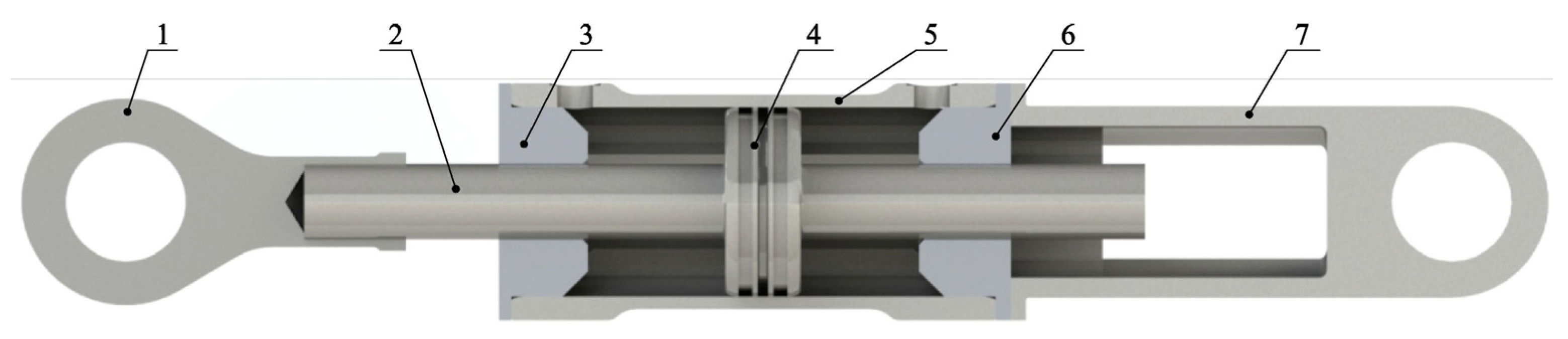
Figure 2.
Manufacturing of CFRP barrels with internal nano-gelcoat: (a) sprayed application of particle–resin mixture; (b) filament-winding process; and (c) cylinders after curing and demolding [20].
Figure 2.
Manufacturing of CFRP barrels with internal nano-gelcoat: (a) sprayed application of particle–resin mixture; (b) filament-winding process; and (c) cylinders after curing and demolding [20].
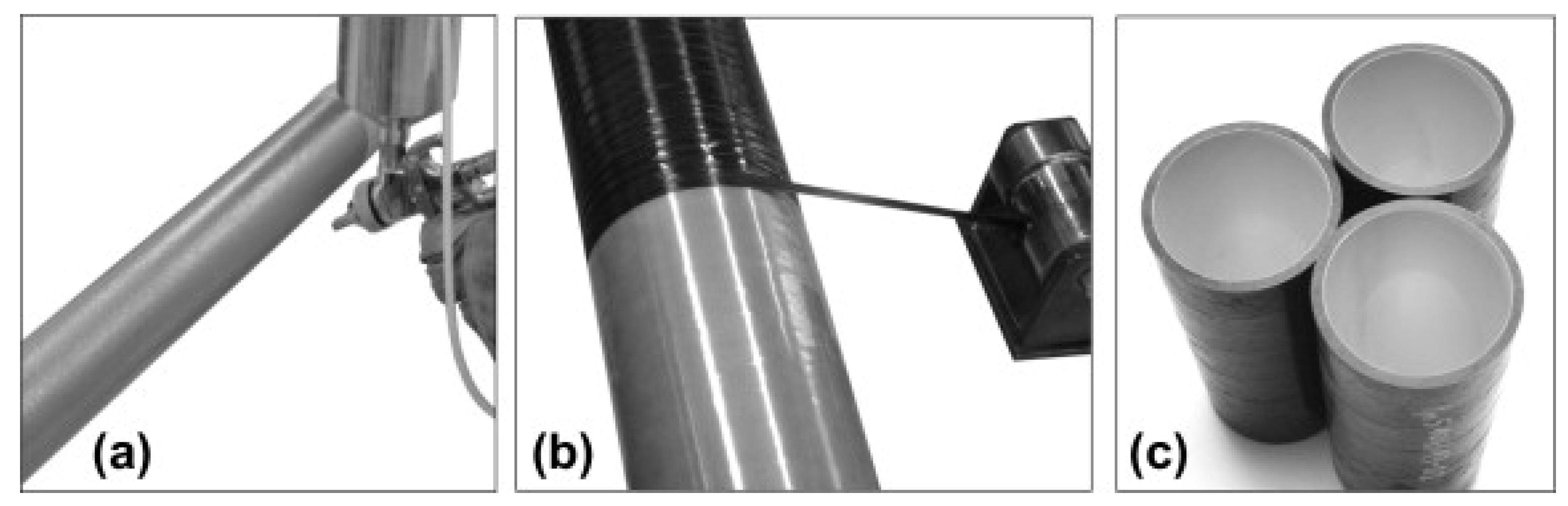
Figure 3.
Test configuration (left) and cross-sectional view (right) of the test set-up [20].
Figure 3.
Test configuration (left) and cross-sectional view (right) of the test set-up [20].
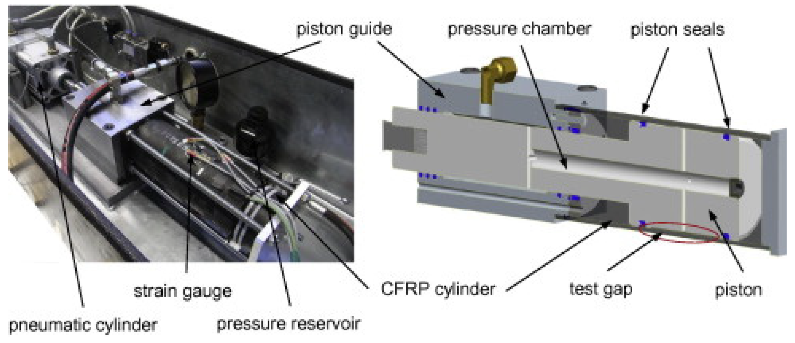
Figure 4.
Geometrical model of an actuator designed by Solazzi [37].
Figure 4.
Geometrical model of an actuator designed by Solazzi [37].
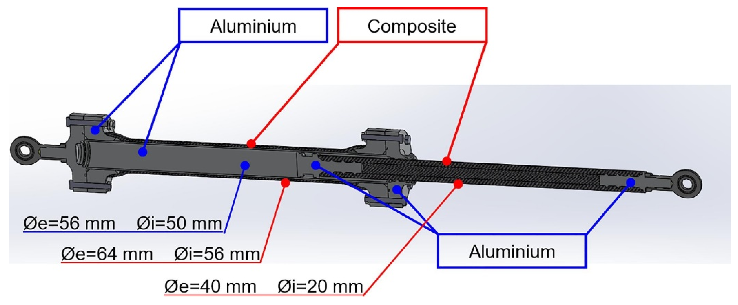
Figure 5.
An actuator prototype designed by Solazzi [37].
Figure 5.
An actuator prototype designed by Solazzi [37].
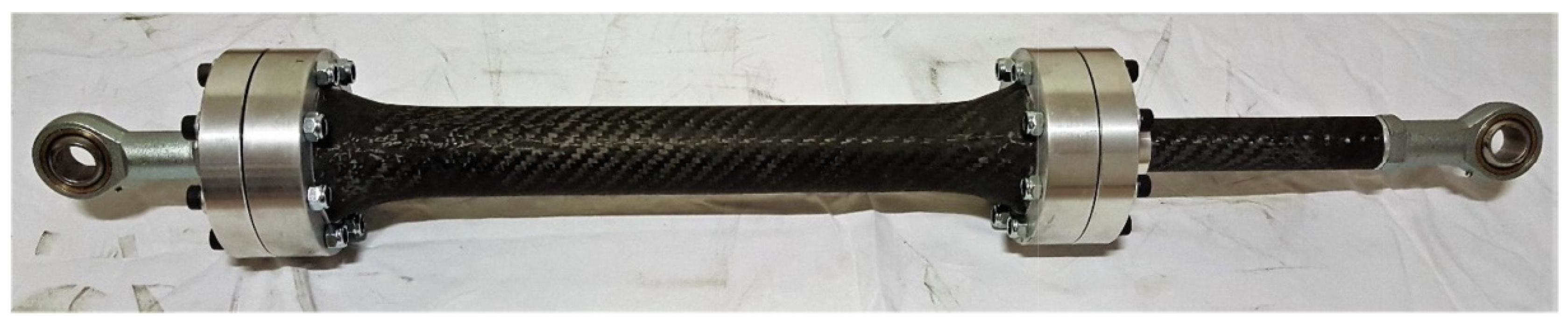
Figure 6.
Three-dimensional-printed pistons integrated with the piston rod and seal [41].
Figure 6.
Three-dimensional-printed pistons integrated with the piston rod and seal [41].
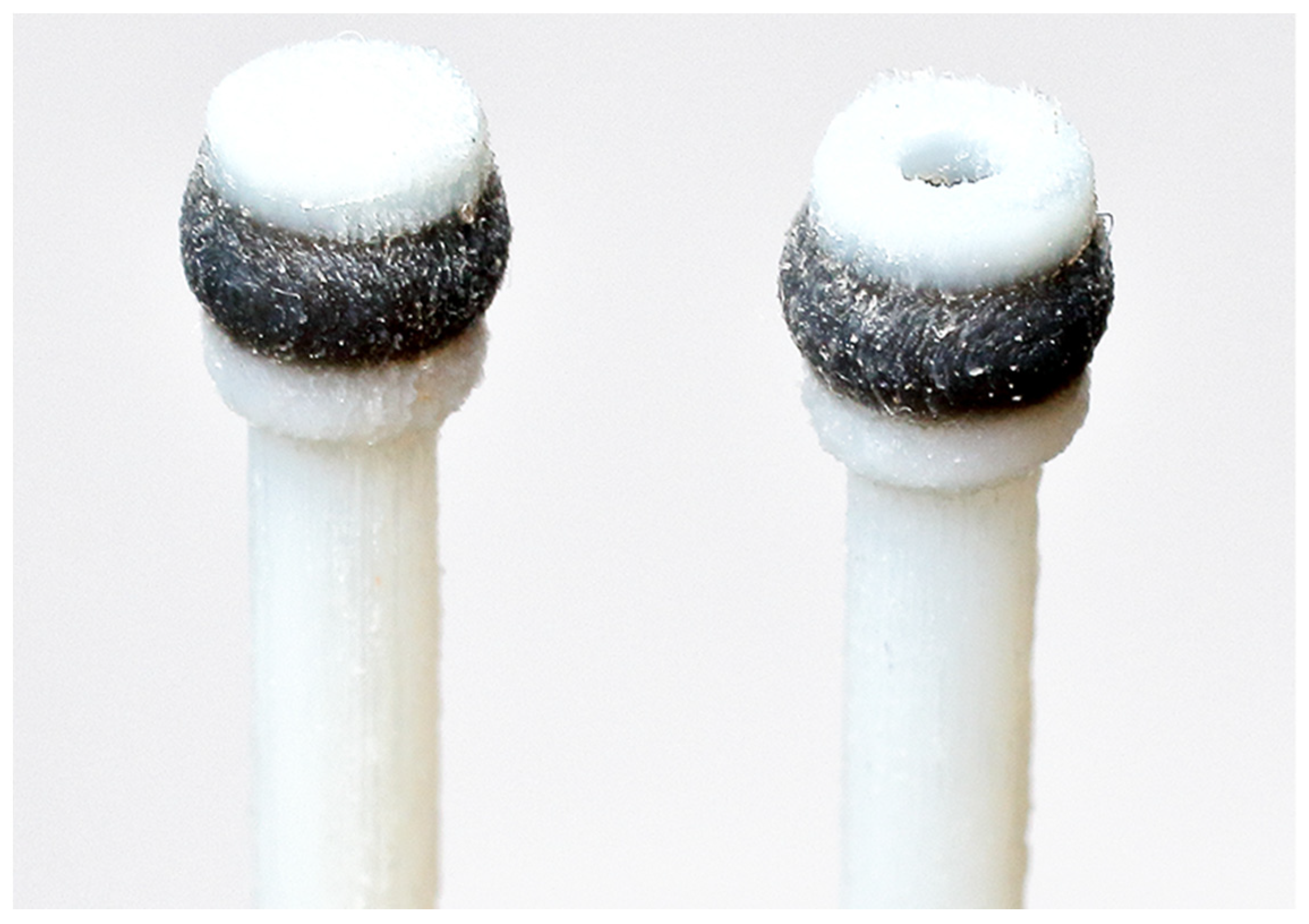
Figure 7.
CFRP hydraulic cylinder prototype designed by Li et al. [2].
Figure 7.
CFRP hydraulic cylinder prototype designed by Li et al. [2].
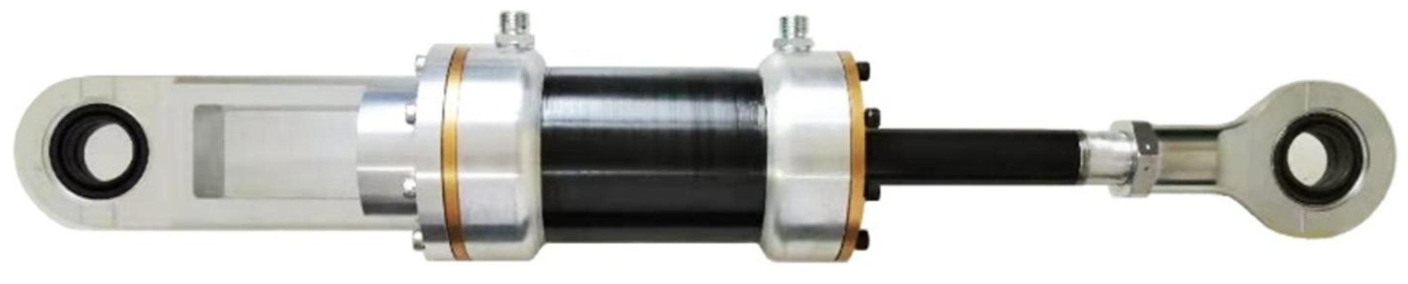
Figure 8.
Schematic visualization of the composite hydraulic cylinder design by Coskun and Sahin [42].
Figure 8.
Schematic visualization of the composite hydraulic cylinder design by Coskun and Sahin [42].
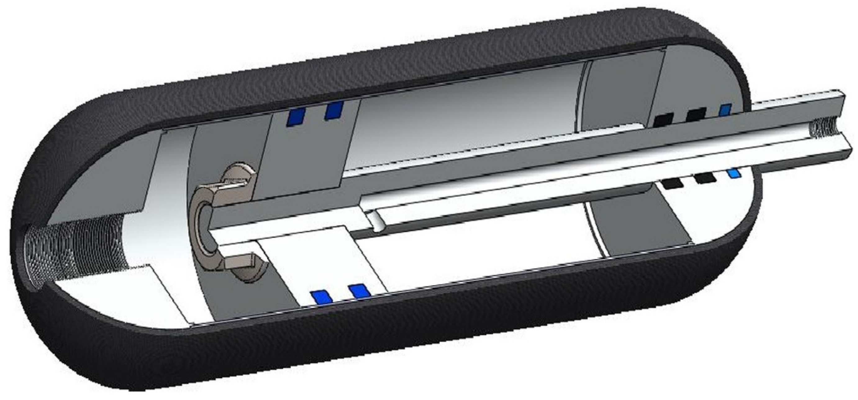
Figure 9.
End cap made of PET plastic tested by Lubecki et al. in [47].
Figure 9.
End cap made of PET plastic tested by Lubecki et al. in [47].

Figure 10.
The connection of actuator elements proposed in patent US4685384A [49]: 1—barrel, 3—piston, 4—piston rod, 5—front cap, 6—front joint, 8—end cap, 9—tail joint, 15—hoop winding, 25—longitudinal winding, 26—retainer ring, 27—retainer wire, 30—circumferential winding, and 35—end plate.
Figure 10.
The connection of actuator elements proposed in patent US4685384A [49]: 1—barrel, 3—piston, 4—piston rod, 5—front cap, 6—front joint, 8—end cap, 9—tail joint, 15—hoop winding, 25—longitudinal winding, 26—retainer ring, 27—retainer wire, 30—circumferential winding, and 35—end plate.

Figure 11.
A form-fit connection of liner and composite overwrap shown in US5415079A [50].
Figure 11.
A form-fit connection of liner and composite overwrap shown in US5415079A [50].

Figure 12.
A method of producing composite barrels with internal threads at the ends [51].
Figure 12.
A method of producing composite barrels with internal threads at the ends [51].
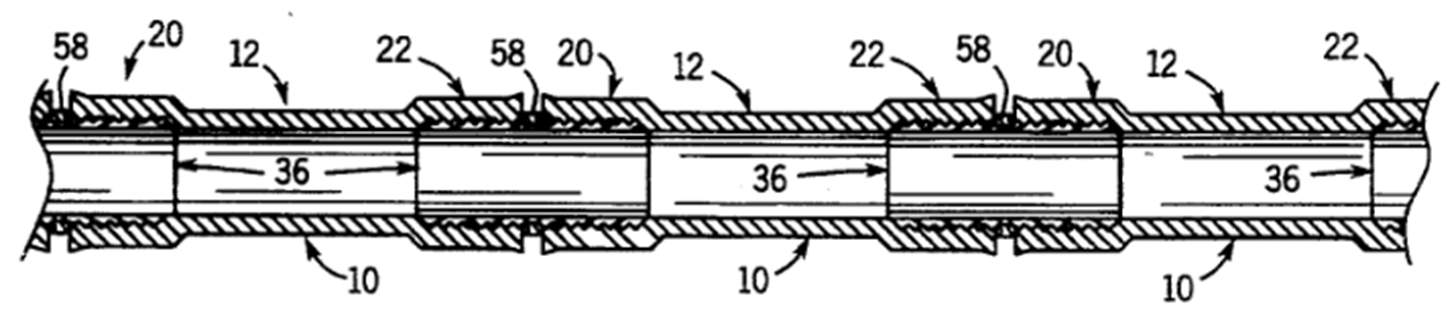
Figure 13.
The method of connecting the composite barrel with the end cap [52].
Figure 13.
The method of connecting the composite barrel with the end cap [52].

Figure 14.
The method of connecting the cylinder and end cap by means of a split ring and screws [53].
Figure 14.
The method of connecting the cylinder and end cap by means of a split ring and screws [53].
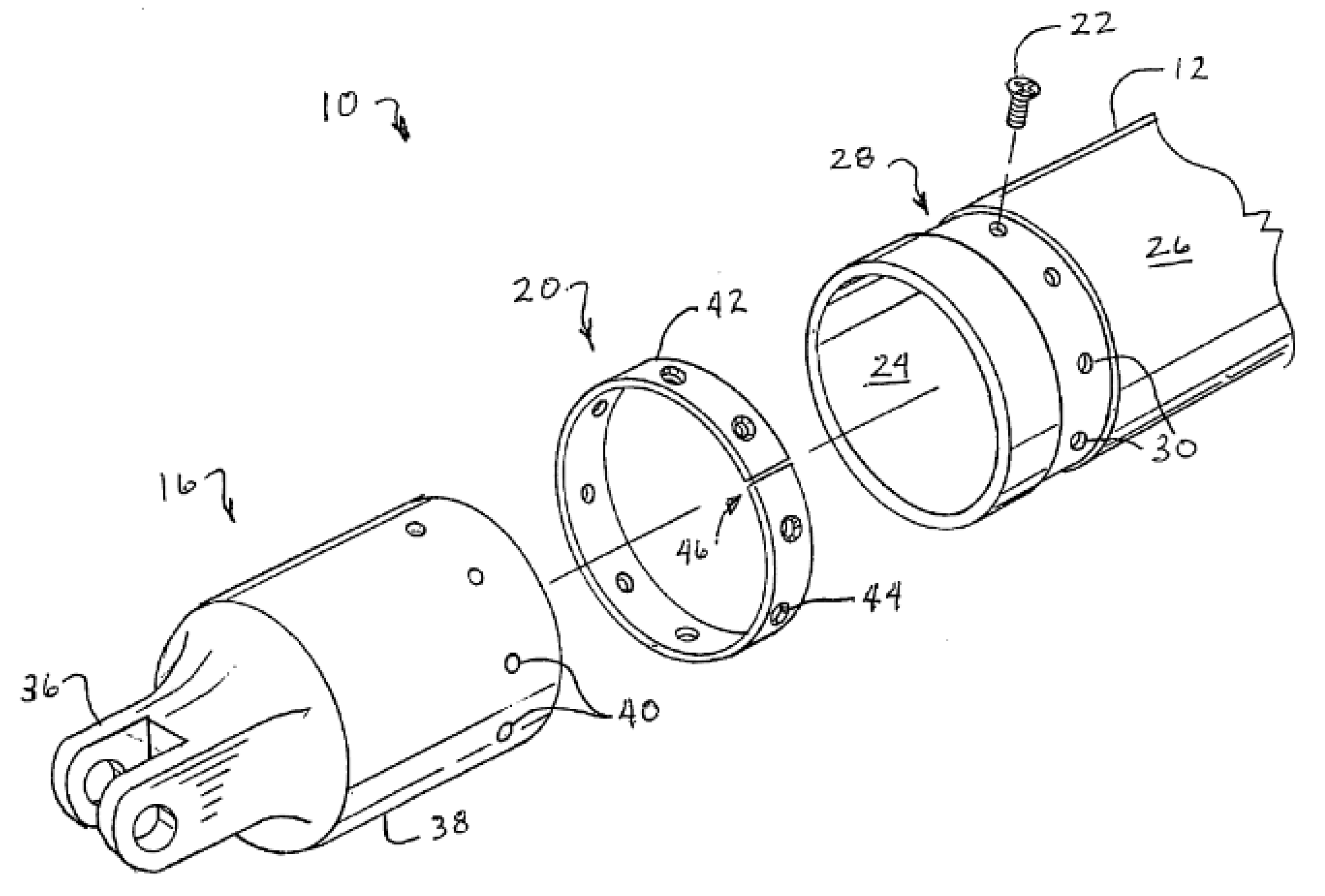
Figure 15.
Examples of Parker Lightraulics actuator designs: (a) a cross-section showing the cylinder structure, (b) a cylinder with a high stroke-to-diameter ratio, (c) a cylinder with a low stroke-to-diameter ratio, and (d) a cylinder with a low stroke-to-diameter ratio with tie-rods [55].
Figure 15.
Examples of Parker Lightraulics actuator designs: (a) a cross-section showing the cylinder structure, (b) a cylinder with a high stroke-to-diameter ratio, (c) a cylinder with a low stroke-to-diameter ratio, and (d) a cylinder with a low stroke-to-diameter ratio with tie-rods [55].
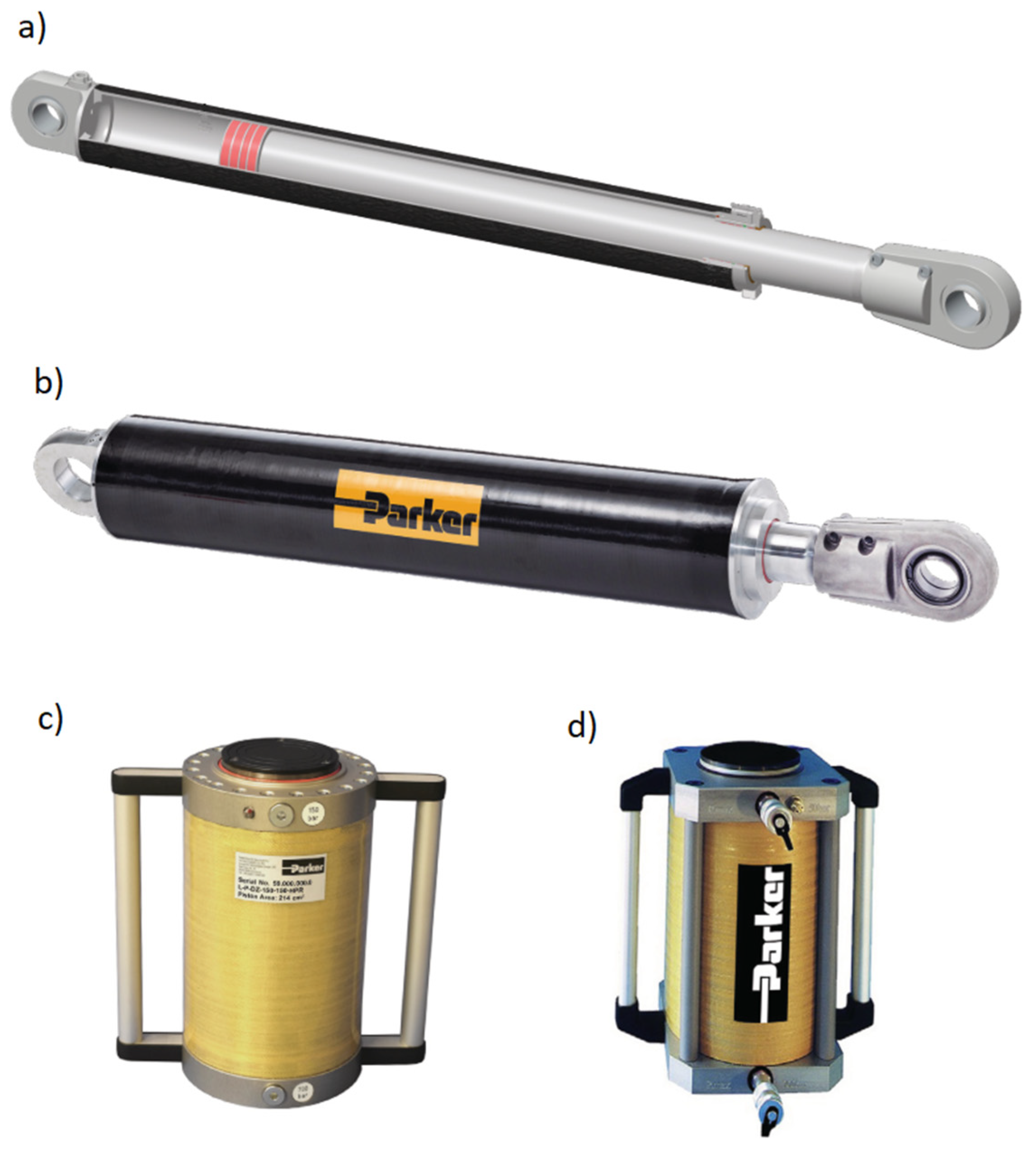
Figure 16.
Various designs offered by Polygon [56].
Figure 16.
Various designs offered by Polygon [56].

Publisher’s Note: MDPI stays neutral with regard to jurisdictional claims in published maps and institutional affiliations. |
© 2022 by the authors. Licensee MDPI, Basel, Switzerland. This article is an open access article distributed under the terms and conditions of the Creative Commons Attribution (CC BY) license (https://creativecommons.org/licenses/by/4.0/).
Share and Cite
MDPI and ACS Style
Lubecki, M.; Stosiak, M.; Skačkauskas, P.; Karpenko, M.; Deptuła, A.; Urbanowicz, K. Development of Composite Hydraulic Actuators: A Review. Actuators 2022, 11, 365. https://doi.org/10.3390/act11120365
AMA Style
Lubecki M, Stosiak M, Skačkauskas P, Karpenko M, Deptuła A, Urbanowicz K. Development of Composite Hydraulic Actuators: A Review. Actuators. 2022; 11(12):365. https://doi.org/10.3390/act11120365
Chicago/Turabian StyleLubecki, Marek, Michał Stosiak, Paulius Skačkauskas, Mykola Karpenko, Adam Deptuła, and Kamil Urbanowicz. 2022. "Development of Composite Hydraulic Actuators: A Review" Actuators 11, no. 12: 365. https://doi.org/10.3390/act11120365
Note that from the first issue of 2016, this journal uses article numbers instead of page numbers. See further details here.