
Develop Real-Time Robot Control Architecture Using Robot Operating System and EtherCAT


1
ADLINK Technology Inc., New Taipei City 235603, Taiwan
2
Department of Mechanical Engineering, National Taipei University of Technology, Taipei 106344, Taiwan
*
Author to whom correspondence should be addressed.
Actuators 2021, 10(7), 141; https://doi.org/10.3390/act10070141
Submission received: 11 May 2021
/
Revised: 16 June 2021
/
Accepted: 20 June 2021
/
Published: 24 June 2021
(This article belongs to the Special Issue Actuators in Robotic Control)
Abstract
:This paper presents the potential of combining ROS (Robot Operating System), its state-of-art software, and EtherCAT technologies to design real-time robot control architecture for human–robot collaboration. For this, the advantages of an ROS framework here are it is easy to integrate sensors for recognizing human commands and the well-developed communication protocols for data transfer between nodes. We propose a shared memory mechanism to improve the communication between non-real-time ROS nodes and real-time robot control tasks in motion kernel, which is implemented in the ARM development board with a real-time operating system. The jerk-limited trajectory generation approach is implemented in the motion kernel to obtain a fine interpolation of ROS MoveIt planned robot path to motor. EtherCAT technologies with precise multi-axis synchronization performance are used to exchange real-time I/O data between motion kernel and servo drive system. The experimental results show the proposed architecture using ROS and EtherCAT in hard real-time environment is feasible for robot control application. With the proposed architecture, a user can efficiently send commands to a robot to complete tasks or read information from the robot to make decisions, which is helpful to reach the purpose of human–robot collaboration in the future.
1. Introduction
In recent years, human–machine collaboration has been an emerging field. In the past, many companies believed that in order to achieve Industry 4.0, a fully automated production model in unmanned factories that replaced all humans with robots was required. For example, traditional automobile manufacturing vendors adopt thousands of industrial robots for full automation and mass production demands. However, unlike these vendors above, many small and medium-sized vendors in the area of electronics manufacturing industry have other requirements to manufacture products with small amounts but customized specifications. Although the price of traditional industrial robots has been decreasing, the high learning curve and high cost of training are still its major disadvantages. Therefore, the human–machine collaboration mode is addressed to satisfy these requirements. In the human–machine collaboration mode, the relationship between humans and machines has changed from giving commands to working together; operators control and monitor production processes, while robots are responsible for repeated and dangerous works. With this cooperation mode of humans and machines, these factories will become more intelligent and efficient in practice. Therefore, the development of collaborative robot control technologies is an essential topic.
Regarding human–robot collaboration (or machines), the area of robotic research in industrial applications seeks approaches for a human–robot interface now [1]. This interface is required not only for simplifying robot programming, but also for the online information exchange in order to obtain status or make decisions. Typical approaches such as teach-pendant, which allows user to program desired positions, and so called “lead-by-the-nose” technique, where users can drag and move the robot by hand to any desired positions, are widely used as human–robot interface today [2]. However, these approaches need proprietary devices and lack user-friendly operation. Recent researches have shown that human–robot interaction technologies can use gesture and voice to guide the robots in a more natural way [3,4,5]. In [3], Microsoft Kinect was used as a sensor and C-sharp programming language was used to recognize user’s gesture and voice commands. Those commands to Kinect will be proceeded by a library to obtain desired positions and fed to robot controller via TCP/IP for robot motion. Similar researches in this area use an ROS framework to integrate various sensors like a vision system and microphones found in [2,6,7,8,9]. In their architectures, ROS acts as a middleware between sensing devices and real robot, and common communication protocols such as TCP/IP are used to send proceeded information from sensors to the robot controller. In the literature [6,7,8,9], it is mentioned that ROS here has easy extensibility and rich functionalities by open-sourced packages, libraries, and tools. The advantages of ROS above, especially its state-of-art motion planning algorithms [10] and build-in communication protocols [11], enables us to adopt ROS for robot control system in this paper and meanwhile retain the compatibility of integrating a human–robot interaction interface in the future.
In the view of robotic development history, ROS is a well-known open source framework that contains thousands of packages and communication protocols for developers to quickly integrate complicated hardware and software to build custom control systems. It was proposed by several researchers from Stanford University in the United States in order to make the traditional development of robots more open and reduce the time it takes for engineers to build a control system to deal with basic configurations or algorithms. In the ROS world, there are many enthusiastic developers who are willing to share their self-developed programs for the benefit of the community. The research report [12] compared the main robotic middleware frameworks in the world and indicated ROS, as a famous robotic middleware, does not support hard real time. Although ROS 2.0 declares that it supports this feature in this report, we still choose ROS as middleware frameworks since ROS 2.0 is still in hard development now. As stated in [13], real-time tasks are required in many robot applications, such as robot motion control, even if ROS does not provide real-time guarantees. Some researches [6,7] focus on developing their own ROS applications in standard Linux and communicate external robot controller via slow serial port or TCP/IP protocol. The performance bottleneck of such architecture may come from the time-consuming communication protocol between non real-time tasks (ROS applications) and real-time tasks (robot control). Thus, some researchers take great efforts to overcome these barriers [14,15,16]. In [14], they proposed a pure software solution for real-time ROS control system based on Xenomai, which contains real-time nodes for robot control and non-real-time nodes for motion planning package MoveIt that run parallel on different threads, and the communication is carried out by ROS action protocol. The research in [15,16] also proposes a real-time control architecture based on Xenomai to control a service robot along with non-real-time ROS packages. Compared to [14] of pure software solution, a Raspberry Pi 3 development board is used in [15]. In [15], most critical communication between ROS node and motor control in this architecture is implemented by so-called cross-domain datagram protocol (XDDP), which is essentially a message-passing mechanism. However, complex message mechanism for communication in ROS is a bottleneck for real-time systems [17].
Considering the obstacles, this paper proposes an architecture of using PC for ROS nodes in standard Linux, which connects an ARM development board via PCI bus for robot control in real-time Linux. By physical dual-port RAM, we can use a shared memory mechanism and design data exchange approaches to solve the communication problem of real-time robot control tasks in ARM development board and non-real-time ROS node tasks in PC. The results of research [18] show that Linux kernels with the PREEMPT_RT patch provide better guarantees of hard real-time performance, and it is suitable for use in time-sensitive embedded control systems. Thus, comparing to Xenomai mentioned above, we try to use PREEP_RT patch to make standard Linux become a real-time system on the ARM development board to execute robot control tasks.
In our architecture, we use the famous ROS MoveIt package that contains state of the art software for motion planning. Zhang et al. [14] reported they use MoveIt to plan a robot trajectory with information about position, velocity, acceleration, and time, and the planned trajectory was sent to the arm controller for the robot control. With this information, the robot controller can use cubic polynomial or quintic polynomial to generate position commands to motor. Here we try to seek an alternative since the environment in the actual production line is quite complicated, and various machines, wiring, and so on are subject to change at any time. Therefore, the robot controller used for human–robot collaboration applications must be able to react immediately in a dynamic environment or unexpected events, such as people touching. Many researchers take great efforts for the demands above to develop approaches that can be used to generate smooth joint space trajectories. Research literature [19,20] proposes a real-time algorithm for time-optimized third-order trajectory that is composed of seven cubic polynomials under extreme conditions such as maximum velocity, acceleration, and jerk, but the algorithm only allows the final velocity to be zero. On the other hand, in addition to the method of connecting trajectories with polynomials, there are also literatures that propose methods to generate trajectories based on FIR filters. Compared with the earlier literature [21], it is proposed to use FIR filter to plan acceleration and deceleration and analyze the roundness contour error in CNC application. The literature [22] proposed a general-purpose speed planning method that can be generated according to different acceleration and deceleration requirements, but it only considers the zero initial and end motion states. In the research literature [23], a dynamic trajectory generation method that allows any initial motion state (velocity and acceleration) is proposed, as long as a simple second-order acceleration-limited trajectory is generated first, and then converted through the FIR filter to get smooth third-order jerk-limited trajectory (jerk-limited trajectory). In this paper, an s-curve velocity planning method is proposed to generate jerk-limited trajectories for actuator control of robot. It is implemented in ARM development board and the advantage of it is to allow the user to specify information and kinematic constraints to describe the trajectory.
Nowadays, in order to avoid the demerits of a centralized control system, Ethernet-based industrial communication protocols including POWERLINK, Ethernet/IP, EtherCAT, and PROFINET, are widely used for automation and control systems in the world. The researches in [24,25] report using Ethernet POWERLINK to build their real-time control system. On the other hand, the industrial Ethernet-based protocol EtherCAT has drawn great attention of researchers [26,27,28,29,30,31], since it provides determinism and real-time control. In [27], researchers presented their works about the implementation and analysis of a motor drive with the EtherCAT. Here, comparing with the EtherCAT software solution in [14], we will execute the EtherCAT stack in ARM development board to communicate between robot controller and servo drive system. The underlying layer of EtherCAT leverages standard Ethernet technologies. It is developed for automation applications that need short data update times with low communication jitter for precise synchronization control and low hardware costs. There are numerous commercial EtherCAT products, such as controllers, I/O device, and servo drive, that appear in the market. CANopen is a communication protocol and device profile specification for embedded systems used in automation. Each CANopen device needs to have an object dictionary used for configuration and communication with the device; communication protocols such like Service Data Object (SDO) protocol and Process Data Object (PDO) protocol; and an application that performs the functions of the device. In this paper, a special device profile (CiA402) for motion control application is used. This device profile supports many kinds of control modes, and the control modes can be switched on the fly. Here, the CSP (Cyclic Synchronous Position) control mode is adopted since it can send synchronized commands from the master controller to multi servo drives of the robot within one cycle time.
The main purpose of this paper is to develop a general real-time robot control architecture for applications, especially for human–robot collaboration, which strongly need audio and vision sensors for interaction. The advantage of the ROS framework here is the capability of connecting sensors to receive human commands and data transfer between modules are easy implemented. Comparing to TCP/IP or message-passing mechanism used by other authors, we propose a shared memory mechanism to improve the communication between non-real-time ROS nodes and real-time robot control tasks. The advantage of the shared memory mechanism is the human commands from sensors can be sent to the robot efficiently, and vice versa. Instead of cubic or quintic polynomial approach, a jerk-limited trajectory generation approach is implemented in real-time motion kernel to obtain fine interpolation of ROS MoveIt planned robot trajectory to motor. Unlike other EtherCAT software solution, the proposed EtherCAT stack executes in the ARM development board for the most-critical communication between robot controller and servo drive systems. Through this, we can deterministically get robot status or send human commands for human–robot collaboration.
This paper is organized as follows. Section 2 introduces how a jerk-limited trajectory is generated in real-time motion kernel to get fine interpolation of MoveIt planned path; Section 3 shows the whole data flow of robot control architecture and its components, and Section 4 shows the experimental setup and results using single actuator. Finally, we discuss the results in detail and make conclusions about this research works.
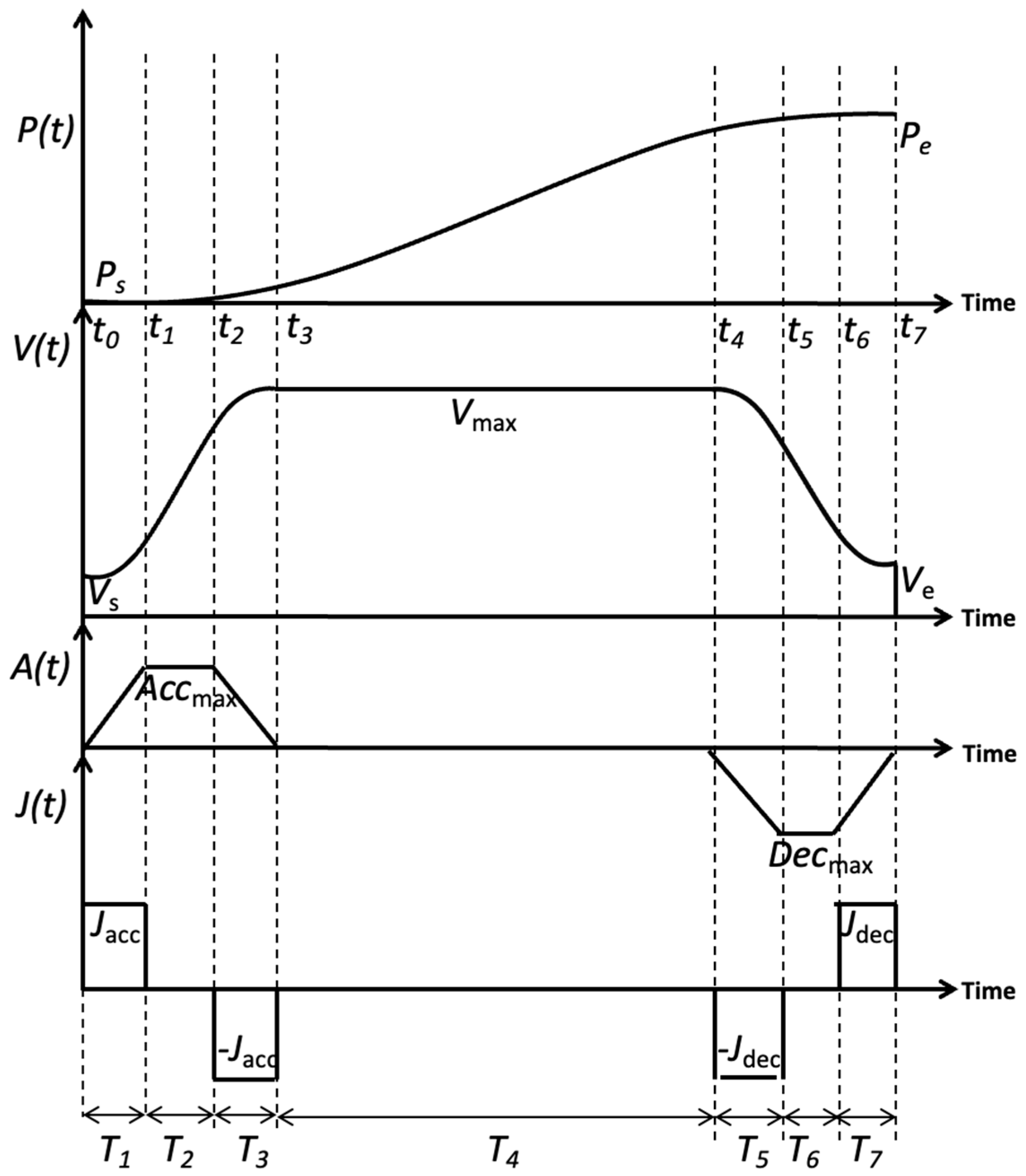
2. Jerk-Limited Trajectory Generation
In this section, an algorithm developed for jerk-limited trajectory generation is introduced. The jerk-limited trajectory generation, using an s-curve velocity profile, as illustrated in Figure 1, can be divided into for the acceleration phase, for the constant velocity phase, and for the deceleration phase respectively. These time intervals have to be integer cycle times for interpolation in a real-time environment. It is important that the time of each cycle should be as small as possible to avoid quantization errors in the results. The symbol is denoted as the time boundary value of each phase. The position and velocity have cubic and parabolic profiles in this schematic. The total distance is important for determination of the shape of the velocity profile. Nonzero start and end velocities are allowed here for serious velocity blending. The maximum velocity is used in the phase. The , , and values are unsigned values. The acceleration (or deceleration) is a trapezoid and linear profile, and its maximum value is (or ). The jerk profile is discontinuous and its maximum value is or (). The acceleration and jerk profiles show the ramping acceleration/deceleration with constant jerk occurring in the and phases, and constant acceleration/deceleration and zero jerk occurring in the and phases. No acceleration, deceleration, and jerk change occurs in the phase. It is assumed that and for a symmetrical profile. The acceleration jerk can be and deceleration jerk . The jerk profile can be expressed as
Integrating (1) with respect to time, the acceleration profile can be written as
Next, integrating (2), the velocity profile is obtained as
and the can be
Finally, integrating (3) with respect to time yields the position profile as
And the can be
If considering the cycle time of digital control system, the time interval and can be obtained respectively by
where and ROUND(.) denotes the round operation. So the adjusted acceleration can be found by
Again, similar operation and Equations (7)–(9) are applied to obtain , , and respectively. Now the time interval can be obtained by considering total distance L
If the condition is held, then we can get modified maximum acceleration, maximum velocity, and maximum deceleration respectively
where . However, if the condition becomes , there is no constant velocity phase since the velocity cannot reach . It is necessary to calculate adjusted maximum velocity
where we can get ,, and respectively. Now, we can replace the initial by , set , and apply Equations (7)–(9) to have modified time intervals and apply Equations (11)–(13) to have modified maximum acceleration, maximum velocity, and maximum deceleration again. Finally, the jerk-limited trajectory can be calculated via integration using the following bilinear transform.
where , , , and are the jerk value, acceleration value, velocity value, and position value of jerk-limited trajectory respectively.
3. Real-Time ROS Control Architecture
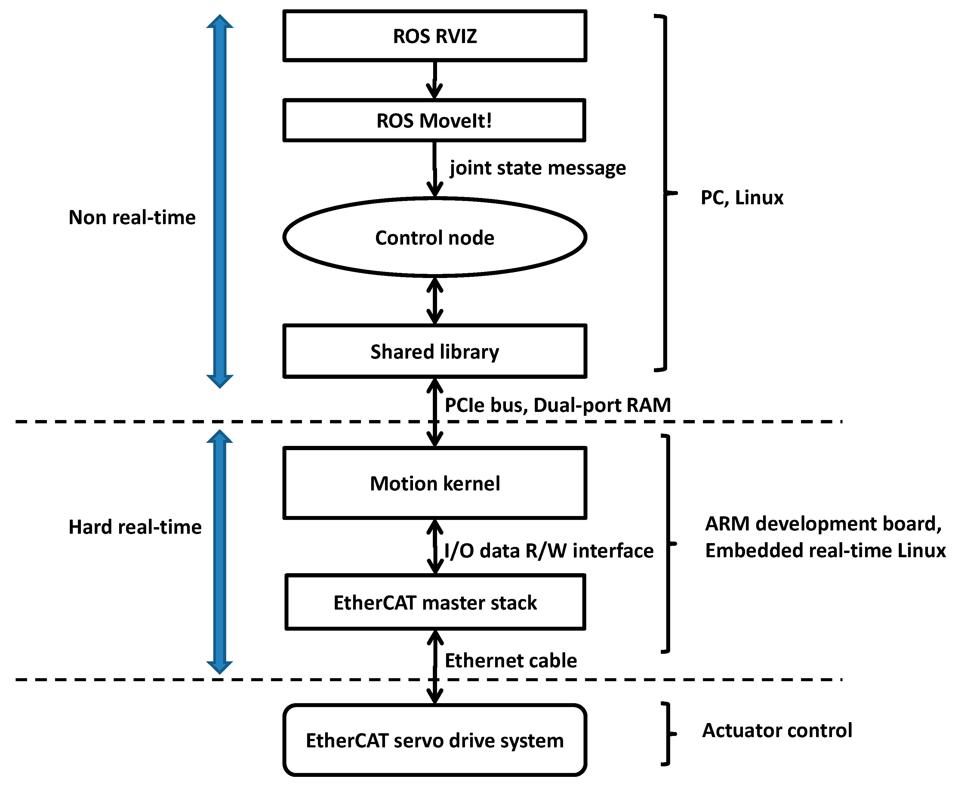
In this section, the details of robot control architecture are presented. Figure 2 shows the data flow diagram of the proposed real-time ROS control architecture that is implemented in PC and ARM development board. In PC, the ROS Melodic is installed in Linux Ubuntu 18.04. The ARM development board with hard real-time motion control kernel and EtherCAT stack implemented inside it is connected to PC via PCIe bus and connected to EtherCAT servo drive via Ethernet cable respectively. This board has a physical dual-port RAM used as shared memory for data exchange between the shared library and the underlying real-time motion kernel.
The control flowchart is described as follows. After booting, the first step is to launch the ROS core, the MoveIt software, related libraries, and other functions we will use step by step. After creating a related ROS control node successfully, we will initialize the real-time motion kernel in ARM development board, set relevant parameters for it, and then tell the moveit_group functions about the name of the group we set in MoveIt. In this control process, we need to specify the target position in Cartesian coordinates into the Position controller in MoveIt for motion planning, and then the control node will call the interface of MoveIt to read the planned trajectory position (unit is radian) back as goal position to the motion kernel to command servo drive via EtherCAT. The unit of these points is converted from radian to pulse for the motion kernel. Meanwhile we can read the command position and feedback position from motion kernel to validate if our actuator’s actual position is correct or not. Next, each component of this architecture will be described in detail.
3.1. RVIZ
RVIZ in ROS is a software used to visualize the control results of a robot. Through RVIZ, we can directly input the position command of the robot arm on this software interface to run the motion plan task or execute the robot to the target position. When the motion planning task detects path interference, the RVIZ screen will display the obstacle in red. If we ignore it and continue to execute the command in this situation, the software will issue an error message to warn that it is a dangerous movement. This warning message can also be read by related topics in an associated state at the same time. These feedback messages are also necessary to plan the path on the fly.
3.2. MoveIt
MoveIt is a high-level robot motion planning software. It has a graphical user interface called MoveIt Setup Assistant for configuration. This interface can help us to generate a file including robot-related parameters and other configuration for collision and interference modules. This interface also supports joint grouping. This interface allows us to specify a ROS controller to adapt either MoveIt or the third party motion planning algorithm for actuator control. No matter if we use position_controllers or Joint Position Controller, we can receive the corresponding information on the topic named “joint_state” as goal position to underlying controller. Thanks to ROS modular design, we can achieve the results of greatly reducing the development time. This interface has special feature to save several robot poses and restore the robot to these poses any time.
MoveIt and its related controller provide a convenient way to move robot pose. For instance, it is supposed that position controller is used as the MoveIt controller. Once the position and pose of the robot end effect is defined in Cartesian coordinates, this position controller can command the end effect to move to the position we specify. The ROS message called “geometry_msgs” provides messages for common geometric primitives such as points, vectors, and poses. These primitives are designed to provide a common data type and facilitate interoperability throughout the system [10]. We use Pose parameter to set the state, but this is simply a simulation and does not actually make the robot move to this value.
It also provides a programming interface named “move_group_interface” that can be used to move the robot or plan a path. When programming with MoveIt, the main user interface is through the “MoveGroup” class. It is convenient to provide functionality for most operations that a user may want to carry out, specifically setting joint or pose goals, creating motion plans, moving the robot, adding objects into the environment, and attaching/detaching objects from the robot [10]. The “setPoseTarget” parameter is used to plan this movement so that the actuator reaches the final position after the algorithm has passed.
3.3. Control Node
A control node to connect the underlying real-time motion kernel by shared library is created here. This control node defines several messages for communication with other nodes via topic protocol. The control node with trajectory planning method will cyclically subscribe a message called “joint state” as a goal position that is published by “MoveIt” to command an actuator to this position. Simultaneously, the control node will receive command position/velocity, feedback position/velocity, and motion status from motion kernel of ARM development board respectively for validation. The command position and command velocity denote the results of position profile and velocity profile. The feedback position and feedback velocity denote the actuator’s actual position and velocity. The motion status is used to indicate whether the requested motion is completed or not. No matter whether the motion is completed or not, the control node can perform trajectory planning algorithms any time and the results will transfer to the ARM development board via shared library to control the actuator.
3.4. Real-Time Motion Kernel
The real-time motion kernel is implemented in ARM development board. It consists of various software modules that are sequentially executed in a synchronized schedule. The first handshake module is responsible for data consistency between kernel and shared library in dual-port RAM. The s-curve velocity planning method implemented in motion kernel is used for joint space jerk-limited trajectory generation, which will generate a smooth position every sampling time under kinematic constraints (maximum velocity and maximum acceleration) to servo drive via EtherCAT. The input of s-curve velocity planning is the current position/velocity and final position/velocity respectively. In addition, maximum speed, maximum acceleration, and jerk factor also need to be given by the user. The output of s-curve velocity planning will provide the interpolator to generate trajectory that is sent to servo drive via I/O data interface using EtherCAT PDO protocol. This algorithm will first calculate a limit distance; if the given distance exceeds the limit distance, there will be a constant velocity movement. Otherwise, it will adjust velocity profile automatically. The trajectory planning algorithm will consider the cycle time of the system, so there will be no truncation errors in the final position and final velocity.
3.5. EtherCAT Stack
The EtherCAT master stack is also implemented in ARM development board. It provides an interface for motion kernel to communicate with underlying servo drive via EtherCAT protocols. The master stack operation is high-precisely synchronized with EtherCAT servo drive under low jitter by distributed clock mechanism to handle real-time process data exchange for motion control application. The process data description can refer to the drive profile defined by CAN in Automation in detail. The proposed motion control architecture adopts cyclic synchronous position mode defined by EtherCAT technology. In this mode, motion control kernel needs send the interpolator’s position to the servo drive via process data named target position and receive the actuator’s real position via process data named actual position simultaneously. Then the interior position control loop in EtherCAT servo drive will command the motor to this position.
4. Experimental Setup and Results
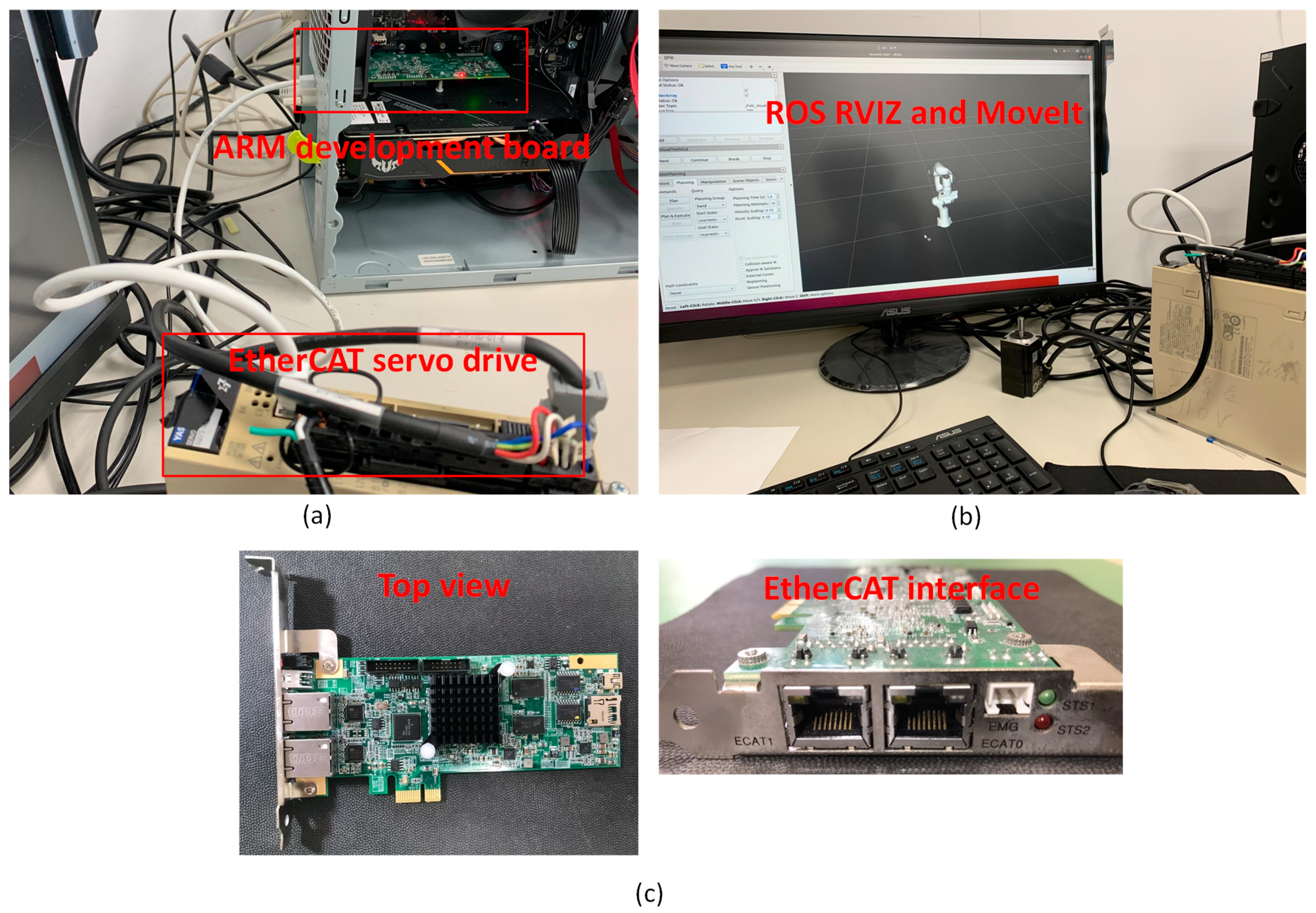
This section will introduce our works to setup the related software and hardware for the actuator control experiment in detail. Figure 3 shows the overview of test devices for experiments. ROS Melodic is installed in Linux Unbutu 18.04 LTS of a personal computer first. The ARM development board (PCIe-8338) is used in this research. Figure 3a shows it is installed in the PCIE slot of PC. With a software development tool, we have the ability to modify standard motion kernel on it and implement related applications and trajectory generation algorithms for research. The EtherCAT stack here is a licensed software that provides API for applications in motion kernel. A well-tuned YASKAWA Sigma 7 EtherCAT servo drive system in Figure 3a is connected to the ARM development board via Ethernat cable. Figure 3b shows the ROS user interface RVIZ on screen and the layout of test devices. Figure 3c shows the top view and EtherCAT interface of the ARM development board. For safety, after setting up the hardware equipment and turning the power on, we need to confirm their status first. This step will check if the board is operating normally and the connection with the servo controller is normal. By inputting command in terminal: roslaunch panda_moveit_config demo.launch, then a virtual seven degree-of-freedom robot arm provided by the ROS community is created to display the motion planning results in RVIZ. It is noticed that only the first axis of the robot arm motor (YASKAWA SGM7J) is connected to a real EtherCAT servo drive system in this experiment. The angle information and speed information of it can be calculated by MoveIt.
Now we can start these software MoveIt and RVIZ, and we need to prepare a launch file named “demo.launch” including the startup and related parameters of the two software in advance. Meanwhile, the related nodes including our control node will also be launched. When our control node is created successfully, it will use shared library to initialize and start the motion kernel in ARM development board. This control node adopts a super loop software model, which uses an infinite while loop to read and write data. There is an internal ROS node named “joint_state_publisher” that will publish the message named “joint_states” from the motion planning results of MoveIt via topic protocol. We need to read this message and send it to motion kernel as the goal position cyclically. In order to prevent blocking of our program, we use the function named “AsyncSpinner” that is a built-in support provided by roscpp for calling callback function from multiple threads. It is equivalent to the standard C++ function of creating a thread. Alternatively, we can also use MoveIt interface function to get the same message efficiently. Based on this programming design, the sampling rate of the control node to this message “joint_states” can reach 500 Hz, which benefits the motion kernel with better command resolution. The MoveIt’s configurations regarding kinematic constraints and original position need to coincide with the motion kernel. Once a new “joint_states” message is read by the control node, we convert the unit from degree to pulse, and then start a point-to-point movement of motion kernel. At the same time, some feedback information are collected for validation.
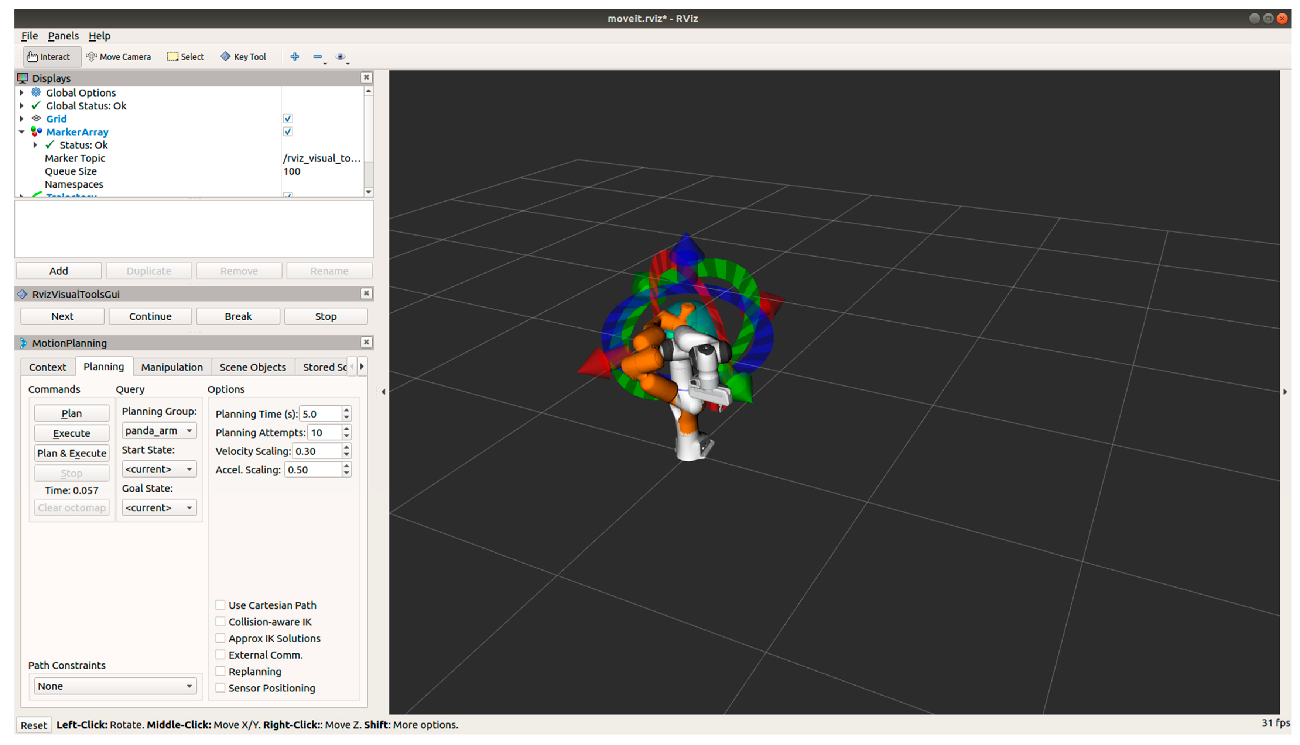
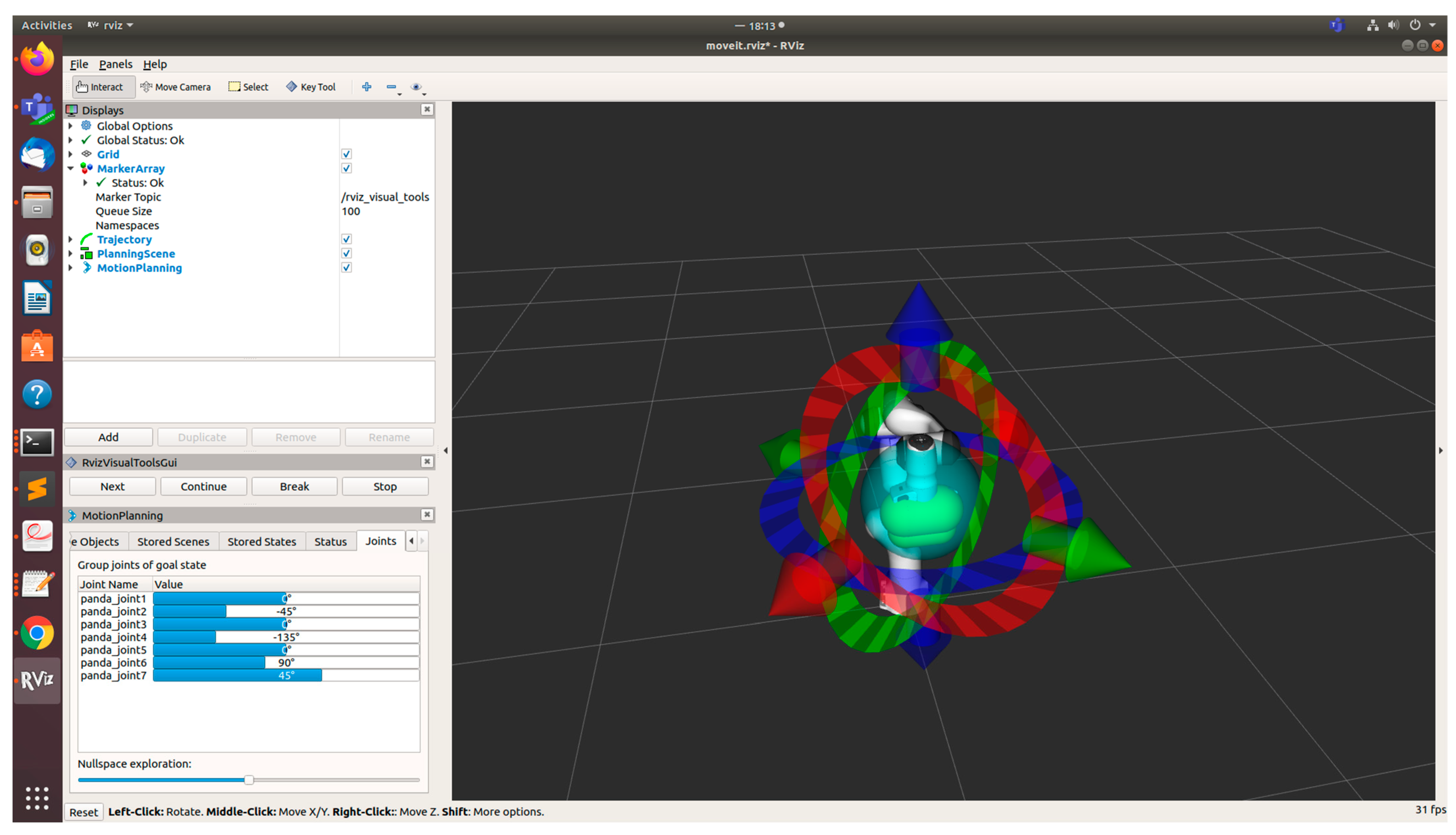
Figure 4 shows the screenshot of RVIZ panel for operation. We can set Velocity Scaling, Accel. Scaling on the panel. The right screen of RVIZ shows the 7 degrees-of-freedom robot. We can directly manipulate the robot arm in RVIZ and then move this robot arm to the arbitrary position. The RVIZ provides three kinds of commands bottoms named Plan, Execute, and Plan & Execute. The Plan command just displays the planned path and does not actually move the robot arm to this position. We can use this command to simulate the robot arm movement and examine the obstacles on the path to prevent collision. The Execute command can make motion kernel execute commands to move the robot arm to the final position along the planned path. The Plan & Execute command is used to run the above two functions at the same time. Figure 5 shows the current position information (angle) of each axis of our arm in RVIZ, and they are used to verify our actuator control experimental results.
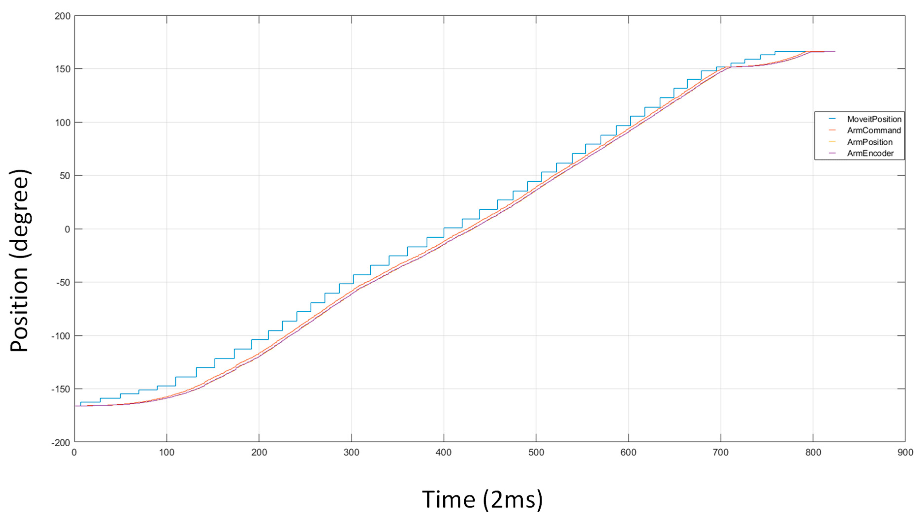
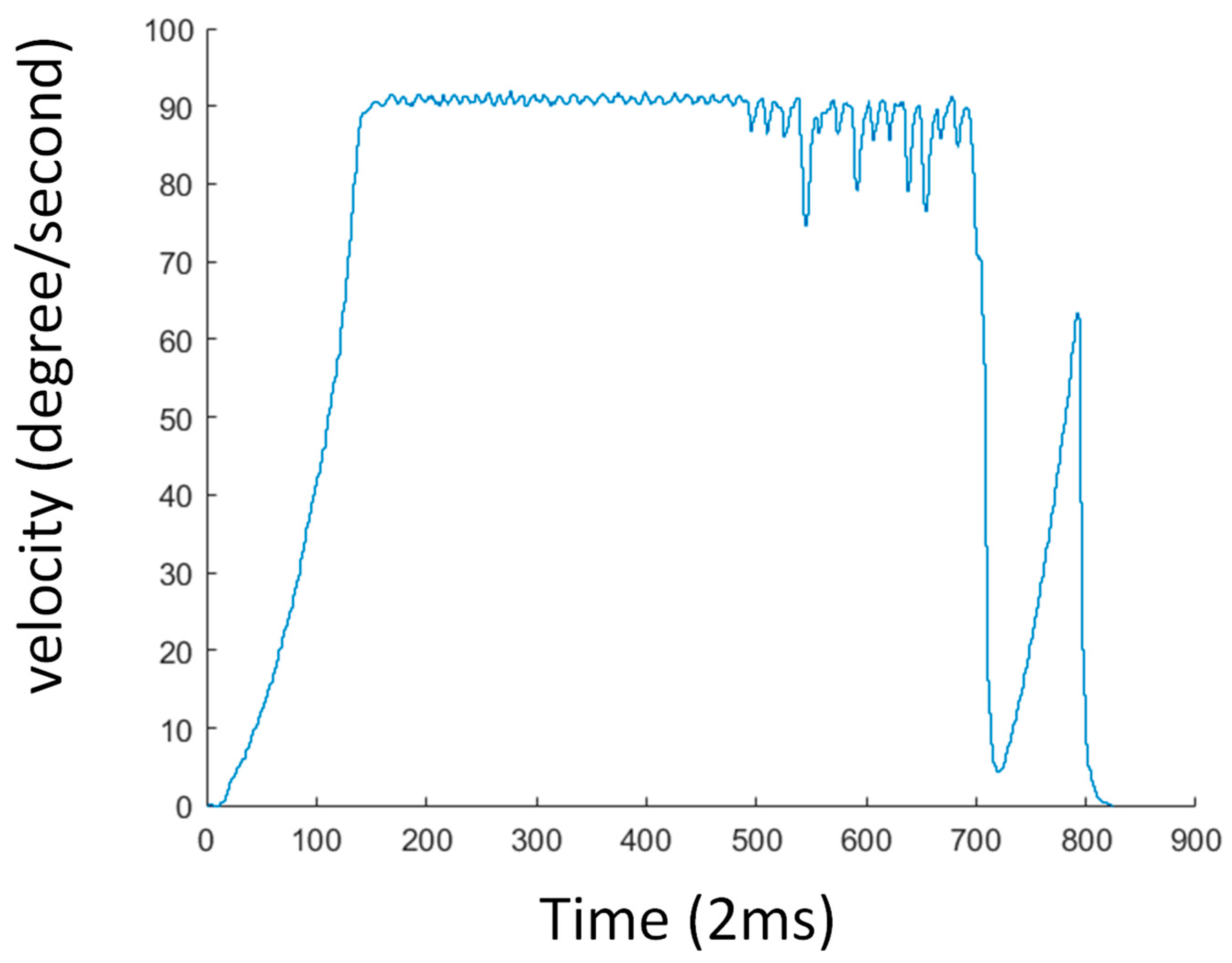
Figure 6 shows experimental results using proposed architecture. It is noticed again that only the first axis of the robot is connected to a real servo drive. The blue line “MoveitPosition” is MoveIt planned path obtained via topic protocol. The command position (ArmCommand), feedback position (Arm Position), and motor encoder (ArmEncoder) are sampled from motion kernel in ARM development board. Every time a control node receives a new “MoveitPosition”, it will interrupt the current motion in motion kernel and generate a new one by proposed trajectory generation approach through the API of shared library. This process will repeat again and again until MoveIt motion planning is completed. The results show the actual position of motor follows the MoveIt planned path well and reaches the desired position (160 degree). Figure 7 shows the feedback velocity trajectory obtained from the same control process and same MoveIt planned path above. We can observe that the max velocity of it obeys the given kinematic constraint (90 degree/second).
5. Discussion
Our tests in the last section in Figure 6 show the ROS communication via topic is evaluated stably, since we can see the goal positions from MoveIt are published every 0.1 s. Although our control node reads these goal positions in free run mode, it is quarantined to send these data to the underlying motion kernel of ARM development board in a synchronized way by handshake protocol. We highlight this, since multi-axis control in the future especially needs this mechanism. The smooth trajectory of command position and feedback position in Figure 6, thanks to the cycle time of time-critical motion control task in motion kernel, can reach 1000 microseconds or less. Again, we have to highlight the distributed clock technology of EtherCAT is used here. By this technology, we can have more confidence to extend current single axis control architecture to multi-axis control in the future. The poor velocity blending results of Figure 6 are introduced by many small line segments and high velocity constraints. We can use look-ahead buffer in the future to avoid problems like this.
We think ROS programming has a certain learning curve for developers to build their own nodes and packages from scratch and integrate them into real systems. It will require some efforts to build ROS infrastructure to manipulate an underlying hardware device via library and device driver. Besides, the embedded software design of motion kernel in ARM development board to handle the motion control and EtherCAT tasks is also a challenge. In order to evaluate its real-time performance, we use Linux API to get a high resolution timer counter to calculate the period time and consuming time of time-critical task in motion kernel. The measurement results show the period of time is 1000 microseconds with low jitter, and the consuming time of it does not exceed 300 microseconds. We must emphasize that our system’s cycle time for motion control and EtherCAT can reach 250 microseconds, which has great benefit to control performance.
In Table 1, we compare the proposed architecture to other ROS-based real-time control systems to analyze the merits and demerits. First, Delgado et al. [15] and this paper use a development board to build real-time systems, but author [14] build theirs in PC. Based on our measured results, the cycle time of real-time tasks using Linux using PREEMPT_RT patch is stable. The difference of real-time OS is not very obvious. The shared memory mechanism of proposed architecture for NRT (non-real-time) task and RT (real-time) task communication is an efficient approach for data exchange, but it needs a user to prevent two tasks writing to the same location simultaneously. The author [14] and this paper use EtherCAT protocol to interact with servo drive system. Here we highlight that our EtherCAT stack supports EtherCAT DC (distributed clock) technology, which is a precision synchronization mechanism. Both authors use ROS packages for motion planning, but we provide a jerk-limited trajectory generation approach to obtain fine interpolation of MoveIt planned path to motor.
So far, this research uses ROS to build a robot control system. The main drawback of it is if master node disappears suddenly, the whole nodes of the system will not work, too. In order to correct it, many developers are undertaking heavy development for a new version called ROS 2.0. With this, our future work will build on our ROS centralized system to ROS 2.0 distributed system to leverage the benefits of DDS (Data Distribution Service) technology [32].
6. Conclusions
The main purpose of this paper is to find approaches for human–robot collaboration, which strongly needs audio and vision sensors for interaction. We present the preliminary research results to assess the feasibility of combining ROS and EtherCAT to develop real-time robot control architecture for it. A high-level ROS MoveIt framework is used for motion planning and a control node is created to adapt ROS and real-time motion kernel of ARM development board. When motion kernel receives a new goal position, it will perform s-curve velocity planning for jerk-limited trajectory generation. Finally, these command positions will send to the servo drive via EtherCAT for actuator control. The experimental results show the actual position of the actuator follows MoveIt planned path well. By the proposed architecture, audio and vision sensors can be easily integrated into ROS to carry out signal processes for recognizing human commands. These commands can be sent to a robot via proposed communication protocols including ROS topic, shared memory mechanism, and EtherCAT. A robot can send information back to a human through the same channels. Therefore, the proposed real-time control system is helpful to reach the requirements of human–robot collaboration in the future.
Author Contributions
Conceptualization, W.-L.C. and Y.-L.Y.; Data curation, M.-H.Y.; Methodology, W.-L.C.; Project administration, Y.-L.Y.; Resources, W.-L.C. and Y.-L.Y.; Software, M.-H.Y.; Supervision, Y.-L.Y.; Validation, M.-H.Y.; Writing—original draft, W.-L.C. and M.-H.Y.; Writing—review & editing, W.-L.C. and Y.-L.Y. All authors have read and agreed to the published version of the manuscript.
Funding
This research received no external funding.
Institutional Review Board Statement
Not applicable.
Informed Consent Statement
Not applicable.
Data Availability Statement
Not applicable.
Conflicts of Interest
The authors declare no conflict of interest.
References
- Berg, J.; Lu, S. Review of Interfaces for Industrial Human-Robot Interaction. Curr. Robot. Rep. 2020, 1, 27–34. [Google Scholar] [CrossRef] [Green Version]
- Deng, H.; Xia, Z.; Weng, S.; Gan, Y.; Fang, P.; Xiong, J. A motion sensing-based framework for robotic manipulation. Robot. Biomim. 2016, 3, 23. [Google Scholar] [CrossRef] [PubMed] [Green Version]
- Kaczmarek, W.; Panasiuk, J.; Borys, S.; Banach, P. Industrial Robot Control by Means of Gestures and Voice Commands in Off-Line and On-Line Mode. Sensors 2020, 20, 6358. [Google Scholar] [CrossRef] [PubMed]
- Torres, S.H.M.; Kern, M.J. 7 DOF industrial robot controlled by hand gestures using microsoft kinect v2. In Proceedings of the 2017 IEEE 3rd Colombian Conference on Automatic Control (CCAC), Cartagena, Colombia, 18–20 October 2017; pp. 1–6. [Google Scholar]
- Mazhar, O.; Ramdani, S.; Navarro, B.; Passama, R.; Cherubini, A. Towards Real-Time Physical Human-Robot Interaction Using Skeleton Information and Hand Gestures. In Proceedings of the 2018 IEEE/RSJ International Conference on Intelligent Robots and Systems (IROS), Madrid, Spain, 1–5 October 2018; pp. 1–6. [Google Scholar]
- Tsarouchi, P.; Athanasatos, A.; Makris, S.; Chatzigeorgiou, X.; Chryssolouris, G. High Level Robot Programming Using Body and Hand Gestures. Procedia CIRP 2016, 55, 1–5. [Google Scholar] [CrossRef] [Green Version]
- Zhang, Y.; Lu, Z.; Wang, C.; Liu, C.; Wang, Y. Voice control dual arm robot based on ROS system. In Proceedings of the 2018 IEEE International Conference on Intelligence and Safety for Robotics (ISR), Shenyang, China, 24–27 August 2018; pp. 232–237. [Google Scholar]
- Megalingam, R.K.; Reddy, R.S.; Jahnavi, Y.; Motheram, M. ROS Based Control of Robot Using Voice Recognition. In Proceedings of the 2019 Third International Conference on Inventive Systems and Control (ICISC), Coimbatore, India, 10–11 January 2019; pp. 501–507. [Google Scholar]
- Bisi, S.; De Luca, L.; Shrestha, B.; Yang, Z.; Gandhi, V. Development of an EMG-Controlled Mobile Robot. Robotics 2018, 7, 36. [Google Scholar] [CrossRef] [Green Version]
- MoveIt! Available online: http://docs.ros.org/en/indigo/api/moveit_tutorials/html/doc/pr2_tutorials/planning/src/doc/move_group_interface_tutorial.html (accessed on 1 May 2021).
- Joseph, L. Mastering ROS for Robotics Programming: Design, Build, and Simulate Complex Robots Using Robot Operating System and Master Its Out-of-the-Box Functionalities; CPackt Publishin: Birmingham, UK, 2015. [Google Scholar]
- Fischer, H.; Vulliez, M.; Laguillaumie, P.; Vulliez, P.; Gazeau, J.P. RTRobMultiAxisControl: A framework for real-time multi-axis and multi-robot control. IEEE Trans. Autom. Sci. Eng. 2019, 16, 1205–1217. [Google Scholar] [CrossRef]
- Wei, H.; Shao, Z.; Huang, Z.; Chen, R.; Guan, Y.; Tan, J.; Shao, Z. RT-ROS: A real-time ROS architecture on multi-core processors. Future Gener. Comput. Syst. 2016, 56, 171–178. [Google Scholar] [CrossRef]
- Zhang, G.J.; Li, Z.; Ni, F.L.; Liu, H. A Real-time Robot Control Framework Using ROS Control for 7-DoF Light-weight Robot. In Proceedings of the IEEE/ASME International Conference on Advanced Intelligent Mechatronics, Hong Kong, China, 8–12 July 2019; pp. 1574–1579. [Google Scholar]
- Delgado, R.; You, B.J.; Choi, B.W. Real-time control architecture based on Xenomai using ROS packages for a service robot. J. Syst. Softw. 2019, 151, 8–19. [Google Scholar] [CrossRef]
- Delgado, R.; You, B.-J.; Han, M.; Choi, B.W. Integration of ROS and RT tasks using message pipe mechanism on Xenomai for telepresence robot. Electron. Lett. 2019, 55, 127–128. [Google Scholar] [CrossRef]
- Jiang, Z.; Gong, Y.; Zhai, J.; Wang, Y.-P.; Liu, W.; Wu, H.; Jin, J. Message Passing Optimization in Robot Operating System. Int. J. Parallel Program. 2019, 48, 119–136. [Google Scholar] [CrossRef]
- Adam, G.K.; Petrellis, N.; Doulos, L.T. Performance Assessment of Linux Kernels with PREEMPT_RT on ARM-Based Embedded Devices. Electronics 2021, 10, 1331. [Google Scholar] [CrossRef]
- Haschke, R.; Weitnauer, E.; Ritter, H. On-line planning of time-optimal, jerk-limited trajectories. In Proceedings of the 2008 IEEE/RSJ International Conference on Intelligent Robots and Systems, Nice, France, 22–26 September 2008; pp. 3248–3253. [Google Scholar] [CrossRef] [Green Version]
- Kröger, T.; Wahl, F.M. Online Trajectory Generation: Basic Concepts for Instantaneous Reactions to Unforeseen Events. IEEE Trans. Robot. 2009, 26, 94–111. [Google Scholar] [CrossRef]
- Chen, C.-S.; Lee, A.-C. Design of acceleration/deceleration profiles in motion control based on digital FIR filters. Int. J. Mach. Tools Manuf. 1998, 38, 799–825. [Google Scholar] [CrossRef] [Green Version]
- Jeon, J.W.; Ha, Y.Y. A generalized approach for the acceleration and deceleration of industrial robots and CNC machine tools. IEEE Trans. Ind. Electron. 2000, 47, 133–139. [Google Scholar] [CrossRef] [Green Version]
- Besset, P.; Béarée, R. FIR filter-based online jerk-constrained trajectory generation. Control Eng. Pract. 2017, 66, 169–180. [Google Scholar] [CrossRef] [Green Version]
- Romanov, A.; Slepynina, E. Real-time Ethernet POWERLINK Communication for ROS. Part I. General Concept. In Proceedings of the 2020 Ural Smart Energy Conference (USEC), Ekaterinburg, Russia, 13–15 November 2020; pp. 159–162. [Google Scholar]
- Romanov, A.; Slepynina, E. Real-time Ethernet POWERLINK Communication for ROS. Part II. Hardware and Software. In Proceedings of the 2020 Ural Smart Energy Conference (USEC), Ekaterinburg, Russia, 13–15 November 2020; pp. 163–166. [Google Scholar]
- Moon, Y.S.; Ko, N.Y.; Lee, K.S.; Bae, Y.C.; Park, J.K. Real-time EtherCAT Master Implementa-tion on Xenomai for a Robot System. Int. J. Fuzzy Log. Intell. Syst. 2009, 9, 244–248. [Google Scholar] [CrossRef] [Green Version]
- Sung, M.; Kim, K.; Jin, H.W.; Kim, T. An EtherCAT-based motor drive for high precision motion systems. In Proceedings of the 9th IEEE International Conference on Industrial Informatics, Lisbon, Portugal, 26–29 July 2011; pp. 163–168. [Google Scholar]
- Sygulla, F. An EtherCAT-Based Real-Time Control System Architecture for Humanoid Robots. In Proceedings of the 2018 IEEE 14th International Conference on Automation Science and Engineering (CASE), Munich, Germany, 20–24 August 2018; pp. 483–490. [Google Scholar]
- Delgado, R.; Choi, B.W. Network-Oriented Real-Time Embedded System Considering Synchronous Joint Space Motion for an Omnidirectional Mobile Robot. Electronics 2019, 8, 317. [Google Scholar] [CrossRef] [Green Version]
- Cereia, M.; Bertolotti, I.C.; Scanzio, S. Performance of a Real-Time EtherCAT Master Under Linux. IEEE Trans. Ind. Inform. 2011, 7, 679–687. [Google Scholar] [CrossRef]
- Rostan, M.; Stubbs, J.E.; Dzilno, D. EtherCAT enabled advanced control architecture. In Proceedings of the 2010 IEEE/SEMI Advanced Semiconductor Manufacturing Conference (ASMC), San Francisco, CA, USA, 11–13 July 2010; pp. 39–44. [Google Scholar]
- Park, J.; Delgado, R.; Choi, B.W. Real-Time Characteristics of ROS 2.0 in Multiagent Robot Systems: An Empirical Study. IEEE Access 2020, 8, 154637–154651. [Google Scholar] [CrossRef]
Figure 1.
S-curve velocity profile for jerk-limited trajectory generation.

Figure 2.
Data flow diagram in proposed ROS control architecture.

Figure 3.
Overview of test devices in laboratory for experiments: (a) ARM development board and EtherCAT servo drive. (b) ROS RVIZ and MoveIt. (c) ARM development board near view.
Figure 3.
Overview of test devices in laboratory for experiments: (a) ARM development board and EtherCAT servo drive. (b) ROS RVIZ and MoveIt. (c) ARM development board near view.

Figure 4.
Screenshot of motion planning configuration displayed in RVIZ control panel.

Figure 5.
Screenshot of current joint states displayed in RVIZ control panel.

Figure 6.
Trajectories of MoveIt planned path (MoveItPosition), command position (ArmCommand), feedback position (Arm Position), and motor encoder (ArmEncoder).
Figure 6.
Trajectories of MoveIt planned path (MoveItPosition), command position (ArmCommand), feedback position (Arm Position), and motor encoder (ArmEncoder).

Figure 7.
Trajectory of feedback velocity.


Table 1.
Comparison of proposed architecture and other researches.
| Authors | Hardware | Real-Time OS | NRT Task and RT Task Comminication | Servo Drive Communication | Motion Planning |
|---|---|---|---|---|---|
| This paper | PC and ARM development board | Linux using PREEMPT_RT patch | Shared memory mechanism | EtherCAT protocol | MoveIt |
| [14] | PC | Xenomai | ROS action protocol | EtherCAT protocol | MoveIt |
| [15] | PC and Raspberry Pi 3 | Xenomai | Mseeage-passing interface (XDDP) | SPI interface | move_base package |
Publisher’s Note: MDPI stays neutral with regard to jurisdictional claims in published maps and institutional affiliations. |
© 2021 by the authors. Licensee MDPI, Basel, Switzerland. This article is an open access article distributed under the terms and conditions of the Creative Commons Attribution (CC BY) license (https://creativecommons.org/licenses/by/4.0/).
Share and Cite
MDPI and ACS Style
Chuang, W.-L.; Yeh, M.-H.; Yeh, Y.-L. Develop Real-Time Robot Control Architecture Using Robot Operating System and EtherCAT. Actuators 2021, 10, 141. https://doi.org/10.3390/act10070141
AMA Style
Chuang W-L, Yeh M-H, Yeh Y-L. Develop Real-Time Robot Control Architecture Using Robot Operating System and EtherCAT. Actuators. 2021; 10(7):141. https://doi.org/10.3390/act10070141
Chicago/Turabian StyleChuang, Wei-Li, Ming-Ho Yeh, and Yi-Liang Yeh. 2021. "Develop Real-Time Robot Control Architecture Using Robot Operating System and EtherCAT" Actuators 10, no. 7: 141. https://doi.org/10.3390/act10070141
Note that from the first issue of 2016, this journal uses article numbers instead of page numbers. See further details here.