Article

Effect of Clearances in Mill Stands on Strip End Motion During Finishing Rolling

Advanced Institute of Manufacturing with High-Tech Innovations AIMHI, Department of Mechanical Engineering, National Chung Cheng University, Minhsiung, Chiayi 62102, Taiwan
*
Author to whom correspondence should be addressed.
Metals 2019, 9(7), 727; https://doi.org/10.3390/met9070727
Submission received: 24 May 2019 / Revised: 17 June 2019 / Accepted: 24 June 2019 / Published: 27 June 2019

Abstract

:
The process stability of finishing mill is significantly influenced by the clearance between the chocks and housing in mill stands. The on-site data of a finishing mill had shown that the clearances in the finishing mill stands were clearly associated with the incidence of strip end flip. The aim of this work was to establish a numerical model to analyze the effect of the clearances on the deviation of the centerline of the strip and on the incidence of strip end flip. By adopting conditions from a particular strip, the numerical model not only predicted the strip end shape, but also visualized strip end flip, which would be otherwise invisible. Four different degrees of asymmetry regarding work rolls and backup rolls were postulated. It was found that the degradation of the work rolls’ clearance level was the most significant influence on the centerline deviation of the strip. Strip end flip was most susceptible to the degradation of the horizontal clearance of the work roll. The simultaneous degradation of the work rolls’ and backup rolls’ level of clearance led to larger reactions and enhanced the asymmetric wear on the liners. The superimposed axial clearances at the roll end provided an axial constraint to the work roll, and were able to reverse the trend of centerline deviation. The numerical results provided a guideline for designing a suitable maintenance strategy for clearances.

1. Introduction

The rapid growing demands on high strength and ultra-thin steel strips have driven the development of finish milling technology to achieve superior strip quality and productivity. The process stability in finishing mill stands is a key factor among the relevant factors that influence quality and productivity. The process stability of finishing mill stands is significantly influenced by the assembly accuracy between the mill stand components. In a four-high mill assembly, work roll chocks and backup roll chocks are mounted in the windows of mill housing. During the finishing process, the high-speed steel strip generates a disturbing load and causes the chattering of the roll chocks in the housing [1].
To absorb the undesirable chattering and axial thrust and avoid the wear of contacting surfaces between mill components, consumable metal liners are installed on chocks and housing faying surfaces with a sufficient narrow range of clearances between them. The liners also provide space for lubrication and thermal expansion [2]. Adequately designed narrow clearances ensure good axial alignment of rolls and guarantee a precise shape and gauge of the strip after finishing. During the finishing process, the initial clearance is gradually broadened over time due to liner wear. The asymmetric wear of chock liners results in the misalignment of rolls, which is commonly referred to as a roll cross. This misalignment leads to a deviation of roll axes from a common plane, and results in additional horizontal loading of the chocks and the housing surfaces, which would further degrade the metal liners. The wear condition and the residual thickness of the liners are crucial to the maintenance strategy of clearances between components. An inadequate clearance range leads to the dynamic instability of the strip during finish rolling, such as snake motion [3], sidewalk [4,5,6], and strip end flip [7,8], which in turn leads to the shape instability of the strip, such as a wavy edge or warping [9].
Strip end flip is the most serious dynamic instability that can occur during the finishing process. It often happens at the instance when the strip end is escaping from the work roll bite of a mill stand. The fluctuation of the strip end could be initiated due to instantaneous tension release. Further fluctuation may lead to undesirable strip end sidewalk, which would cause the strip to hit the side guides located at the entrance of the next mill stand and further result in a flip phenomenon at the strip end. As a result, the flipping strip end would damage the work rolls, leave indents on the work rolls, and thus cause serious consequences in production [10]. According to statistics, the incidence of strip end flip is less than 5% during finishing rolling; nevertheless, its occurrence is usually unpredictable due to its random characteristic. On-site data from the finishing line of the China Steel Corporation (CSC) Kaohsiung had shown that the clearances in finishing mill stands were clearly associated with the incidence of the strip end flip. The statistics also show that the regular maintenance of the liners was effective in suppressing the incidence of the strip end flip.
The maintenance strategy of the clearances has so far been planned on the basis of empirical and statistic on-site data. There has been some research regarding the effect of clearance on the wear of the liners [11,12]. Some work was also done on the statically indeterminate problem of rolls crossing due to asymmetric clearance using an analytical model [13,14]. However, no literature or research was found that focused on the effect of the clearances in the finishing mill stand on the finishing stability, or more precisely, on the strip end behavior during the finishing process. To elaborate an on-site experiment at the finishing line would be unfeasible. Therefore, the aim of this work is to establish a finite element numerical model to analyze the collective effect of the clearances on the deviation of centerline of the strip and on the incidence of the strip end flip.

2. Introduction to Assembly of Finishing Mill Stand and Clearances

The finishing mill stand in a hot rolling mill typically consists of two to seven four-high mill tandem stands. Each stand consists of housing and a vertical assembly made up of two work rolls (WR) and two backup rolls (BR) within the housing. The backup rolls and the work rolls are supported on each end in the individual stand by bearing chock assemblies, which are mounted in the windows of the mill housing. In a four-high mill assembly, there are two pairs of work roll chocks and two pairs of backup roll chocks. The work roll assembly can be removed as a unit from the work side (WS) of the mill for ease of maintenance. Figure 1 provides a perspective view of a mill stand including housing, a pair of working rolls, a pair of backup rolls incorporated with chock, and liner assemblies depicted in a removed state relative to the mill stand housing.
The horizontal clearances (CH) and the axial clearances (CA) in a mill stand are illustrated in Figure 2a and Figure 3a, respectively. The horizontal clearance is defined as the width of the housing inner frame subtracted by the width of the chock along rolling direction. According to the definition, the front gap and the rear gap are considered as one clearance, as shown in Figure 2b. Furthermore, the work roll chock had a flange and a web part. Liners are installed at mating surfaces at the flange and at the web. The clearances at the flange and at the web are almost of the same magnitude according to the on-site measurement; they are usually categorized as one horizontal clearance. Therefore, there are eight horizontal clearances, as numbered in Figure 2a. The axial clearance (CA) is the spacing between the keeper (thrust clamp) liners and chock arm liners. For each roll, there is a front and a rear axial clearance, as depicted in Figure 3b, and there are also eight axial clearances in a mill stand. Liners are replaced periodically, and the clearances need to be carefully monitored during maintenance. The maintenance on liners is less frequent than the maintenance on the work roll assembly.

3. FEM Modeling and Methodology

Finite element numerical simulation using explicit solver ABAQUS was explored to analyze the effect of the clearances on the strip end motion and instantaneous reactions between chocks and housing in finishing mill stands. The strip motion and strip end flip were simulated under different clearance configurations. The severity of clearance configurations was evaluated.

3.1. Finishing Mill and Clearance Model

An analytical model describing the dynamic equations of motions of the strip during a stable finishing process was introduced in [4]. Finishing parameters such as reduction, mill modulus, roll deformation, tension of the strip, and restraint moment were considered as variables that would affect the strip motion. Yet, the strip end flip is a transient phenomenon ofan unstablestrip motion associated with instantaneous tension release.This would further alter the loading conditions exerted on the rollers of the two consecutive participating mill stands. The strip end motion becomes quite complicated, and is difficult to be modeled analytically.
On-site data from CSC Kaohsiung show that the strip end flip is most likely to occur between the third (F3) and the fourth (F4) finishing stand. Analysis on the instantaneous strip motion through consecutive finishing stands was explored by establishing a simplified yet representative model consisting of twin tandem mill stands with the dimensions and setup adopted from the F3 and F4 stands in the CSC finishing line. A moving strip model was incorporated with the finishing mill model, which allows a visualization of the instantaneous strip end motion at the moment of the strip end leaving the roll bite. The F3 and F4 model incorporating a strip is illustrated in Figure 4. The operation parameters and clearance configurations were adopted from the on-site data of a particular strip on which the strip end flip had occurred at F4. The F3 mill stand in the model was applied simply as a roll bite that provides the clamping support of the strip during transmitting and upon escaping. A tension of 10 t in magnitude was applied to the front of the strip model to facilitate the continuous finishing. Thus, the backup rolls were neglected from the F3 model for simplicity. While the crownless work roll models of F3 and F4 were considered analytically rigid, the backup roll model in F4 was considered as discretely rigid in order to satisfy the contact condition with the work rolls upon numerical computation. The dimensions and the associated operation parameters are listed in Table 1 and Table 2, respectively.
The chocks and the housing were considered rigid. Since the clearances at the flange and at the web were almost of the same magnitude according to the on-site measurement, they were usually categorized as one horizontal clearance. The chock model can be simplified into a horizontal beam element with the reference point (Rp) at the center and two extended reference points (Rpex) at the front and rear ends, as illustrated in Figure 5a. The length of the beam elements represents the width of the chock. In F4 model, eight horizontal clearances (CH) and eight axial clearances (CA) were established between chocks and housing using connector elements. A connector element is a linear element that connects two reference points and restrains the degree of freedom between them. The horizontal clearance (CH) was established by connecting the Rpex on the chock to the Rp on the housing frame surface, as depicted in Figure 5a. A pair of axial clearances (CA) between the keeper and chock arm also can be established by connecting the Rpex on the chock to the Rp on the keeper, as depicted in Figure 5b. The allowable clearance range can be limited by the connector elements. The initial clearances adopted from on-site data are listed in Table 3 and Table 4.

3.2. Strip Modeling

As mentioned in Section 3.1, the data of the strip end model were adopted from the on-site data of a particular strip of SAE1016 low carbon steel on which strip end flip had occurred at F4. The strip end model had initial dimensions of 5.67 m (L) × 1.20 m (W). The initial state of the strip upon beginning the simulation was that the strip end was about to leave the roll bite of F3. The initial thickness varied from 7.1 mm before F3, 4.3 mm between F3 and F4, and 2.8 mm after F4, as schematically shown in Figure 4. In addition, an initial camber of 53 mm to the work side (WS) at the rear part of the strip measured between F3 and F4 was also adopted from the on-site data, as illustrated in Figure 6. To ensure a smooth deformation within the roll bite, the strip model was finer meshed along the rolling direction than along the width direction. There were 1140 (L) × 30 (W) × 2 (t) elements, or 68,400 in total. The dimension of the 3D elements of type C3D8R was then 5 mm (L) × 40 mm (W) × 2.15 mm (t). The finishing temperature of the strip was set at 900 °C.
The flow curves of the SAE1016 low carbon steel were obtained from dynamic upset compression test using a GLEEBLE 3500 simulator under various strain rates. Details on how the flow curves were obtained can be drawn from [15]. The resulted flow curves are shown in Figure 7 and were applied as the constitutional model in the finite element computation. Interpolation or extrapolation of the curves was applied to the flow data for temperature and strain rate conditions lying in between. The SAE1016steel had a density of 7832 kg/m3, a Young’s modulus of 213 GPa at room temperature, and 97 GPa at 900–1000 °C. The Poisson ratio was 0.33.

4. Results and Discussion

4.1. Strip End Motion Simulation

The simulation of instantaneous strip end motion was visualized at various moments in Figure 8a–c. Figure 8a,b depicts the instantaneous position and shape of the strip end at t = 0.48 s and t = 0.72 s, respectively. The centerline of the strip deviated from the centerline of the finishing mill to the work side (WS). The deviation of strip could be effectively limited by a pair of side guides. With the side guide installed, collision between the strip and side guide occurred at t = 0.62 s. Then, the strip end began to flip upward at t = 0.84 s, as shown from another perspective in Figure 8c. Usually, upper guides are applied at the entrance of the roll bite of each finishing mill stand to prevent the strip end from flipping against the work roll surface. Due to the tight and compact design between consecutive mill stands, a direct observation or image recording on the strip end flip phenomenon is visually blocked. This simulation work not only predicted the instantaneous strip end shape, but also visualized the strip end flip, which would be otherwise invisible. The detailed technique was described in [15].
The centerline deviation of the particular strip obtained from on-site data and of the simulated ones was compared in Figure 9. The blue solid line denotes the centerline deviation of the particular strip. The data was recorded by an image sensor installed behind the mill stand. The curve of the centerline deviation first bent in the direction of the WS, and when the strip sidewalk was limited by the side guide with an opening of about 40 mm on each side, an inversion of the centerline curve was observed, indicating the correction of the strip centerline by the side guide. The simulation result of strip end motion without the constraint of the side guide shows a curved centerline deviation in the direction of WS, which is shown as a red dotted curve. If the side guide was added to the numerical model, the deviation curve (black dotted line) exhibited a deflection at t = 0.62 s and then an inversion in the direction of DS, indicating the contact of the strip with the side guide followed by the subsequent inversion of the centerline and the beginning of the strip end flip. The consistency of the simulated results and the on-site data in trend demonstrated the ability of the numerical model to further predict the deviation of the centerline and dynamic behavior of the strip end under various clearance configurations. The on-site recorded curve revealed somewhat of an inconsistency with the simulated one after t = 0.62 s. This is mainly because that the strip end began fluctuating and flipping after collision with the side guide. The centerline position of the strip end was first recorded by video camera and then decoded into position data. The irregular curve shape after t = 0.62 s in Figure 9, to some extent, reflects the irregular flipping of the strip end, which cannot be exactly simulated by the numerical model.

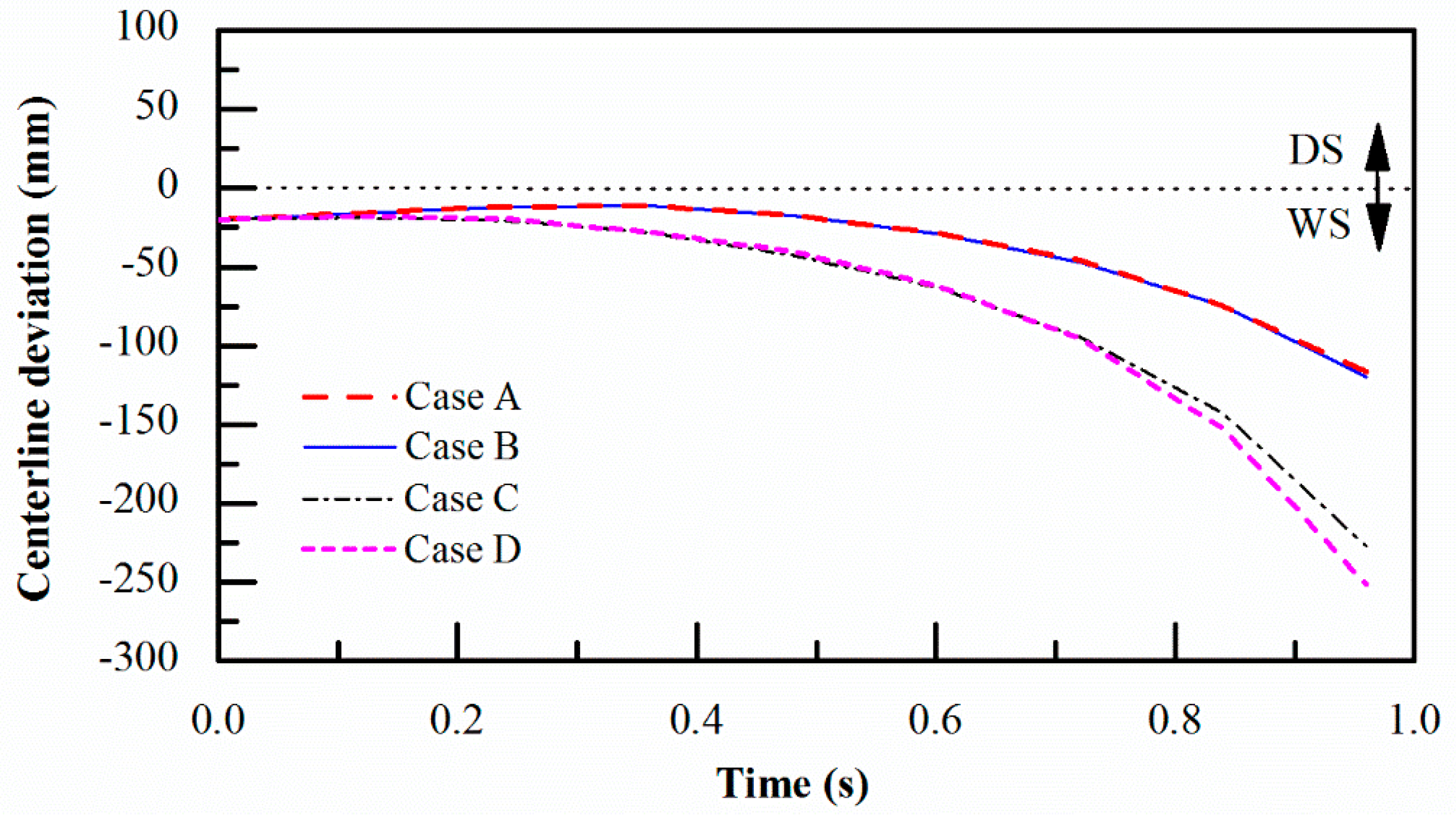
4.2. Effect of Horizontal Clearances on the Centerline Deviation

The management of horizontal clearance in the CSC finishing line, which is based on empirical data, is divided into four levels, as tabulated in Table 5. The work rolls require less clearance than the backup rolls. Clearances should be carefully monitored and checked during maintenance. Should the clearances reach level three or higher, the liner must be replaced in order to restrict the clearances below safety levels.
If the liners on both the WS and DS exhibit the same or a similar level of clearances during operation, there would be no concern regarding asymmetric wear. However, as long as asymmetric clearance levels become serious between the WS and the DS, the misalignment or cross-over of work rolls and backup rolls may occur, and would lead to the instability of the mill stand, such as the chattering of chocks, or undesirable strip motion such as sidewalk, excess camber, or strip end flip.
To discover the trend of influence, we postulated four different cases of asymmetry of work rolls and backup rolls by combining different clearance levels of work roll chock and backup roll chock, as listed in Table 6. Case A represents the least severe asymmetry by setting all the clearance levels at level 1. There are still slight clearance differences between the WS and DS: 0.5 mm − 0.2 mm = 0.3 mm for the work roll, and 0.7 mm − 0.5 mm = 0.2 mm for the backup roll. In case B, the asymmetry between the WS and DS is only set at the backup roll by setting level 4 at the WS and level 1 at the DS. In case C, contrary to case B, the asymmetry is only set at the work roll. Case D has the most severe asymmetry; both the work roll and backup roll bear clearance level 4 at the WS and level 1 at the DS.
Figure 10 shows the simulation results regarding the effect of asymmetry of the clearances on the deviation of strip end centerline. Both case A and case B exhibit very similar results. Upon increasing the degree of asymmetry of the backup roll to the largest difference between WS and DS in case B, the centerline deviation did not differ with that of the least asymmetry in case A. It can be deduced that the degradation of the clearance level from a very safe side of level 1 to a maintenance-must level 4 of the backup rolls did not substantially affect the strip motion and centerline deviation. Naturally, the centerline deviation would be insusceptible if the clearance level were only degraded to level 2 or level 3.
Contrary to case B, a degradation of clearance level from level 1 to level 4 on the work roll in case C caused a significant increase in the centerline deviation that was almost twice that of cases A and B. If the degradation of clearance level from level 1 to level 4 is applied to both the work roll and backup roll, as in case D, the deviation of the centerline became more serious than that in case C. As depicted from Figure 10, contact of the strip end with the side guide would occur if the centerline deviation exceeds the side guide opening. Thus, the strip end flip is very likely to occur in case C and case D.
The centerline deviation curves of other combinations of less susceptible levels can be interpolated between that of the case A and case D. It can be summarized that the degradation of clearance level on the work rolls most significantly affects the centerline deviation of the strip. The strip end flip is most susceptible to the degradation horizontal clearance of the work roll.

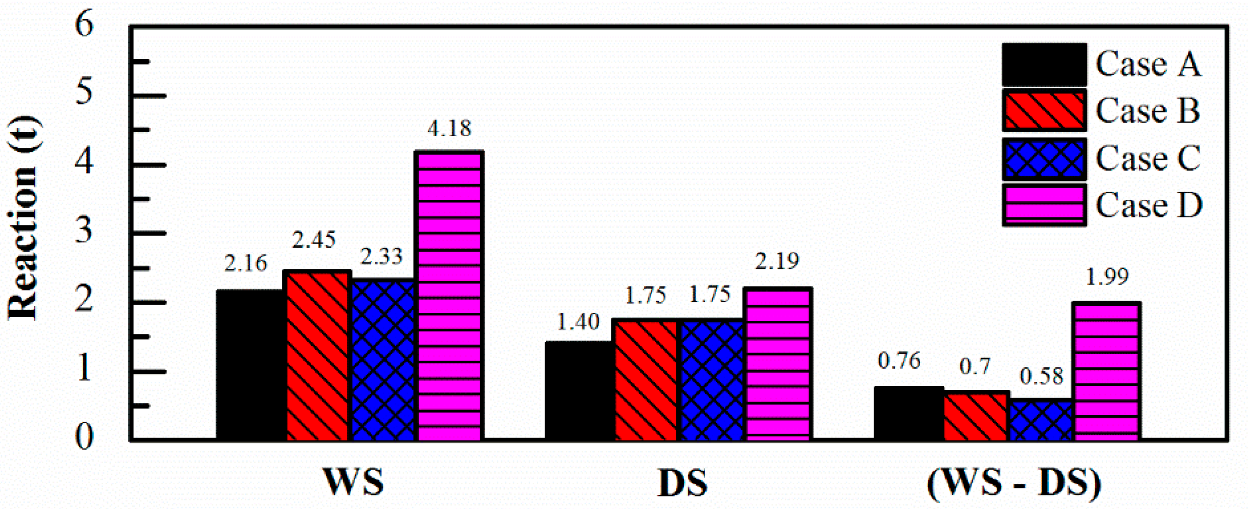
4.3. Effect of Horizontal Clearance on the Reactions between Roll Chocks and Housing

The degradation of the clearance level between the chocks and housing as well as the degradation of alignment of the rolls would deteriorate the metal liners during the finishing process. It is interesting to investigate the reactions between the roll chocks and housing. Knowledge of the magnitude of the reactions is useful in evaluating the liner wear, and provides a quantitative database for the planning of the maintenance period of the chock lines.
Figure 11a,b illustrates the reaction history between roll chocks and housing at the WS and at DS, respectively. Figure 11c shows the difference of the reaction between the WS and DS. In general, randomly distributed compressive reactions less than 7.0 t were predicted. The average reactions at the WS and DS and reaction difference between WS and DS are illustrated in Figure 12. Among the four cases, case D, at which the most severe levels of clearance were applied, exhibited the highest average reaction, which was about twice as large as those of the another cases. Since the clearance at the WS was slightly larger than that at the DS, as illustrated in Table 6, larger reactions were expected at the WS. Similar to the reaction history, the largest average reaction at the WS and the DS occurred in case D. The reaction difference denotes the force asymmetry between the WS and the DS. Simultaneous deterioration of the level of clearance on the work rolls and the backup rolls in case D significantly led to larger reactions and would enhance the asymmetric wear on the liners. As a consequence, this would further promote the wear of the liners.

4.4. Effect of AxialClearance on the Centerline Deviation

The on-site records from the finishing line revealed one finding: the incidence of strip end flip significantly reduced after the axial liners between the keepers and chock arms had been maintained. The axial clearance CA management in the CSC finishing line, as listed in Table 7, is also divided into four levels. The allowable range of axial clearance is slightly wider than that of horizontal clearances. As summarized in Section 4.2, the strip end flip was most susceptible to the degradation of the horizontal clearance level and the asymmetry of the work rolls. Therefore, in this section, different levels of axial clearance of 3 mm (level 4), 1 mm (level 1), 0.5 mm (level 1), and 0.3 mm (level 1) were superimposed on case C in Section 4.2 to investigate the effect of the axial clearance on the centerline deviation.
The centerline deviation caused by the initial case C is plotted as a solid curve in Figure 13. The superimposed axial clearances at the roll end provided an axial constraint on the work roll. With decreasing axial clearance, the trend of centerline deviation was gradually reversed, as depicted in Figure 13. The reversing effect was more significant at the tighter axial clearance of 0.3 and 0.5 mm. Without superimposing axial clearance, the strip end flip was susceptible to the asymmetry of horizontal clearance, since the centerline deviation exceeded the side guide opening.
In case C, an asymmetric condition of horizontal clearance of 3.0 mm at the WS and 0.2 mm at the DS was given to the lower work roll. Without the constraint of keepers, or with a loose axial clearance, the work roll chocks on both sides would be pushed by the drag force until the chock faces were held by the mating faces of the housing. There would be a misalignment of the work roll between WS and DS of 2.8 mm, as schematically illustrated in Figure 14a. The work roll exhibits a slight angle of misalignment. By providing a tight yet required axial clearance of 0.5 to 0.3 mm to the work roll, the chock arms are subjected to a restraint of the keepers and, as a result, the misalignment of the work roll would be significantly reduced, as schematically expressed in Figure 14b. Consequently, the centerline deviation is effectively reduced to a safe range free from strip end flip. It can be elucidated that a tight enough axial clearance reduced the susceptibility of strip end flip to the horizontal clearances. Thus, the interaction between the horizontal and the axial clearance is evaluated.
In this work, the simulation results not only numerically reproduced the strip end flip phenomenon, but also showed a quite similar centerline deviation to that obtained from on-site recording. Thus, the ability of the numerical tool developed in this work had been verified. Based on this verified model, further simulation of more clearance combinations using the numerical tool will be able to provide more quantitative indices to improve the liner maintenance strategy to a more precise one.

5. Conclusions

Finite element simulation was explored to analyze the effect of the clearances on the centerline deviation of the strip and strip end flip during the finishing process. Both the horizontal and axial clearances were taken into consideration. The results of this work have illustrated how the strip end motion was affected by the combination of different clearance levels. The following conclusions can be drawn from the results:
  • A numerical model of the finishing mill has been created, consisting of the third and fourth finishing stand and incorporating a strip end model. The ability of the numerical tool in predicting the strip end motion was verified by successfully duplicating a strip end flip phenomenon under identical clearance configuration adopted from on-site data of a particular strip in finish rolling.
  • The instantaneous strip end motion, including the strip end flip between the mill stands, was numerically visualized at different times. The effect of the clearance on the centerline deviation of the strip was predicted.
  • The effect of horizontal clearance on the strip motion and the reaction between the housing and chock was investigated by examining the strip centerline deviation under conditions where the work roll and backup roll had different degrees of asymmetry. The centerline deviation of the strip end and the strip end flip were susceptible to the degradation of the horizontal clearance level of the work rolls. In contrast, the asymmetry of the backup roll alone had only a minor effect on the centerline deviation. The degradation of clearance level also resulted in a higher reaction to the liners, which would accelerate the wear of liners.
  • Tight axial clearances imposed a restraint at the roll ends and had the effect of reducing or suppressing the misalignment of the work roll caused by the asymmetric horizontal clearance levels. As a result, the centerline deviation of strip and the incidence of strip end flip could be significantly reduced.
  • The numerical results provided a qualitative guideline for designing a suitable maintenance strategy for clearances.

Author Contributions

Methodology, H.-K.H. and J.-N.A.; software, H.-K.H.; validation, H.-K.H.; formal analysis, H.-K.H.; writing—original draft preparation, H.-K.H. and J.-N.A; writing—review and editing, H.-K.H. and J.-N.A; project administration, J.-N.A.

Funding

This research was funded by the Ministry of Science & Technology of R.O.C. (Taiwan) and the China Steel Corporation in Kaohsiung under grant number MOST 102~106-2622-8-006-001, 1, MOST 106-2221-E-194-013-MY3 and MOST 107-2218-E-468-004.

Acknowledgments

The Ministry of Science & Technology of R.O.C. (Taiwan) and the China Steel Corporation in Kaohsiung are acknowledged for their support of the funding of this research. The authors are grateful to the Hot Rolling Division of China Steel Corporation (CSC) Kaohsiung for their providing on-site data and for their valuable discussion.

Conflicts of Interest

The authors declare no conflict of interest.

References

  1. Corts, J. Linear Bearing Plate for Rolling Mill. U.S. Patent No. US 8,353,192 B2, 15 January 2013. [Google Scholar]
  2. Zheng, T.; Li, M. Development of statically determinate plate rolling mills that maintain the rolls parallel. J. Manuf. Sci. Eng. 2013, 135, 031014:1–031014:8. [Google Scholar]
  3. Ishikawa, T.; Tozawa, Y.; Nishizawa, J. Fundamental study on snaking in strip rolling. Trans. ISIJ 1998, 28, 485–490. [Google Scholar] [CrossRef]
  4. Washikita, Y.; Isei, Y.; Buei, Y.; Aihara, Y.; Takeda, M. Strip Walking Control Technology in Hot Strip Rolling; Technical Report, No. 111; Control Research Lab, Process Research Laboratories: Futtsu, Japan, 2016. [Google Scholar]
  5. Kiyota, T.; Matsumoto, H.; Adachi, Y.; Kondo, E.; Tsuji, Y.; Aso, S. Tail crash control in hot strip mill by LQR. In Proceedings of the 2003 American Control Conference, Denver, CO, USA, 4–6 June 2003; pp. 3049–3054. [Google Scholar]
  6. Choi, Y.J.; Min, C.L. PID sliding mode control for steering of lateral moving strip in hot strip rolling. Int. J. Control Autom. Syst. 2009, 7, 399–407. [Google Scholar] [CrossRef]
  7. Costa, A.; Dornelas, F.; Costa, R.; Fontes, L.; Salles, A. CST Arcelor Brasil HSM Tail-end Crashing Reduction Using Six Sigma Methodology. In Proceedings of the Iron & Steel Technology Conference, Indianapolis, IN, USA, 7–10 May 2007. [Google Scholar]
  8. Kiyota, T.; Matsumoto, H.; Adachi, Y.; Tsuji, Y.; Kondo, E. Improved linear model of hot strip mill for tail crash control. Trans. JSME 2004, 190, 70–695. [Google Scholar]
  9. Abdelkhalek, S.; Montmitonnet, P.; Legrand, N.; Buessler, P. Coupled approach for flatness prediction in cold rolling of thin strip. Int. J. Mech. Sci. 2011, 53, 661–675. [Google Scholar] [CrossRef]
  10. Aoh, J.N.; Hsu, H.K.; Chen, M.F. Numerical approach on the reproduce of a strip end flip phenomenon in finishing mill. In Proceedings of the 12th International Conference on Technology of Plasticity ICTP, Cambridge, UK, 17–22 September 2017. [Google Scholar]
  11. Furumoto, F.; Kanemori, S.; Takeguchi, T. Reduction of off centering at tail end caused by unstable work roll position with mill stabilizing device in hot rolling. In Proceedings of the 12th International Conference on Technology of Plasticity ICTP, Cambridge, UK, 17–22 September 2017. [Google Scholar]
  12. Shen, G.; Li, M. Statically determinate characteristics of micro displacement in a four-high mill. J. Mater. Process. Technol. 2009, 209, 5002–5007. [Google Scholar] [CrossRef]
  13. Shen, G.; Yu, C.; Ren, Z.; Xing, J.; Xiao, H. Mechanism generating deviations in the rolling load and strip camber on the plate rolling mill. Ironmak. Steelmak. 2017, 44, 707–711. [Google Scholar] [CrossRef]
  14. Wang, X.; Li, F.; Li, B.; Dong, L.; Zhang, B. Design and application of an optimum backup roll contour configured with CVC work roll in hot strip mill. ISIJ Int. 2012, 52, 1637–1643. [Google Scholar] [CrossRef]
  15. Hsu, H.K.; Aoh, J.N. The Mechanism of Position-Mode Side Guide in Correcting Camber in Roughing Process of a Hot Strip Mill. Metals 2019, 9, 504. [Google Scholar] [CrossRef]
Figure 1. Viewofafinishing stand.
Metals 09 00727 g001
Figure 2. Illustration showing horizontal clearances (CH). (a) Location of horizontal clearances, (b) details of work roll chock clearances.
Metals 09 00727 g002
Figure 3. Schematic illustration showing axial clearances (CA). (a) Location of axial clearances, (b) axial clearances between chock arms and keepers.
Metals 09 00727 g003
Figure 4. The model of F3 and F4 finishing mill stands incorporating a strip.
Metals 09 00727 g004
Figure 5. Clearance modeling using connector elements. (a) horizontal clearance, (b) axial clearance.
Metals 09 00727 g005
Figure 6. Center line profile of the strip model showing an initial strip end camber.
Metals 09 00727 g006
Figure 7. The flow curves of the SAE1016 at 900 °C.
Metals 09 00727 g007
Figure 8. Instantaneous strip shape showing centerline deviation at (a) t = 0.48 s (top view), (b) t = 0.72 s (top view). (c) Strip end flip occurred at t = 0.84 s (rear view).
Metals 09 00727 g008
Figure 9. Comparison of centerline deviation between on-site record and simulated results.
Metals 09 00727 g009
Figure 10. Comparison of centerline deviation resulting from the various asymmetries of the horizontal clearances of rolls.
Metals 09 00727 g010
Figure 11. Comparison of reactions at chocks and housing resulting from different asymmetry of horizontal clearances of rolls. (a) WS, (b) DS, (c) difference between WS and DS.
Metals 09 00727 g011
Figure 12. Average reactions at WS and DS and reaction difference between WS and DS.
Metals 09 00727 g012
Figure 13. The effect of the superimposed axial clearances on correcting the centerline deviation.
Metals 09 00727 g013
Figure 14. Schematic illustration on misalignment of the work roll influenced by different degrees of axial clearances between keepers and chock arms. (a) Loose axial clearance, (b) tight axial clearance.
Metals 09 00727 g014
Table 1. Dimensions and mass of rolls in finishing mill.
ComponentsDimensions
3rd and 4th stand work roll Length 2.03 m/Diameter 0.73 m
4th standbackup roll Length 1.73 m/Diameter 1.4 m
Work roll/chockMass 6 ton/10 ton
Backup roll/chockMass 30 ton/15 ton
Table 2. Finishing parameters of F3 and F4.
Finishing ParametersValue
F3 traverse speed3.93 m/s
F4 traverse speed5.96 m/s
F3 reduction0.39
F4 reduction0.34
F3 friction coefficient0.24
F4 friction coefficient0.24
Tension on strip10 t
Table 3. On-site clearances CH in a finishing mill in China Steel Corporation (CSC) Kaohsiung.
CHWork Side (WS) (mm) Drive Side (DS) (mm)
Top backup roller 2.582.63
Top work roller 1.691.26
Bottom work roller 1.881.84
Bottom backup roller 1.321.81
Table 4. On-site clearances CA in finishing mill in CSC Kaohsiung.
CAFront (mm) Rear (mm)
Top backup roller 1.511.35
Top work roller 0.820.46
Bottom work roller 1.792.53
Bottom backup roller 1.812.68
Table 5. The horizontal clearance management levels in the finishing line.
CHLevel 1Level 2Level 3Level 4
Top backup roll (mm)<2.02.0–2.52.5–3.03.0–4.0
Top work roll (mm)<1.51.4–22.0–2.52.5–3.0
Bottom work roll (mm)<1.51.4–22.0–2.52.5–3.0
Bottom backup roll (mm)<2.02.0–2.52.5–3.03.0–4.0
Table 6. The different asymmetry of horizontal clearances of rolls in the numerical model.
Location of CHSide Case ACase BCase CCase D
CHLevelCHLevelCHLevelCHLevel
Top backup roll (mm)WS0.710.710.710.71
DS0.510.510.510.51
Top work roll (mm) WS0.510.510.510.51
DS0.210.210.210.21
Bottom work roll (mm)WS0.510.513.043.04
DS0.210.210.210.21
Bottom backup roll (mm)WS0.713.040.713.04
DS0.510.510.510.51
Table 7. Axial clearance management levels in the finishing line.
CALevel 1Level 2Level 3Level 4
Top backup roll (mm)<2.02.0–3.03.0–4.04.0–5.0
Top work roll (mm)<1.51.5–2.02.0–2.72.5–3.0
Bottom work roll (mm)<1.51.5–2.02.0–2.72.5–3.0
Bottom backup roll (mm)<2.02.0–3.03.0–4.04.0–5.0

