1. Research Background
Plasma nitriding is a surface technology to dope nitrogen atoms into metal surfaces via plasma chemical reactions to improve wear resistance, and fatigue strength, etc., of materials [
1,
2,
3,
4,
5,
6,
7,
8,
9,
10,
11,
12,
13,
14,
15,
16]. Plasma nitriding is now one of the essential surface treatments used in industry, especially in the automobile industry and die/mold fabrication. Conventional plasma nitriding uses low-pressure DC (or pulsed DC) plasmas in the abnormal glow discharge mode, where the batch process with a large vacuum furnace meets the purpose of mass production. In addition, a number of low-pressure plasma modes have recently been applied to nitriding treatment, e.g., active screen plasmas [
4,
5,
6], electron cyclotron resonance plasmas [
2,
7], and radio-frequency plasmas [
8], etc.
As another technological seed, nitriding methods using atmospheric-pressure plasmas have been developed, where the disuse of vacuum equipment makes the process much quicker and easier-to-operate. Two types of atmospheric-pressure plasmas are utilized to nitriding, namely the pulsed-arc (PA) plasma jet [
17,
18,
19,
20,
21,
22] and the dielectric barrier discharge (DBD) [
23,
24]. The PA plasma-jet nitriding has proved to be available to die steel [
17,
18,
22], austenitic stainless steel [
20], and titanium alloy [
19,
21], where the jet plume is sprayed onto the sample surface to thermally diffuse nitrogen atoms into it. Note that the nitrogen/hydrogen gas mixture is used as the operating gas. The plasma-jet nitriding will offer a drastically economical method to us compared with conventional plasma nitriding, especially when high-mix low-volume production is targeted.
The plasma-jet nitriding, however, is a relatively new, still developing technology. Thus, its controllability and reliability has to be improved further for practical application. For example, we had no methods to control the nitrogen dose amount from the jet plume to the metal surface, while such a method has been completed for conventional nitriding in which the nitrogen dose is well-controlled by adjusting the nitriding potential [
25]. Due to the lack of dose controllability, the plasma-jet nitriding suffers from a problem of excess nitrogen supply due to the high pressure results in undesirable formation of voids and iron nitrides (the compound layer) attributed to nitrogen gas precipitation in the treated metal surface.
In this paper, a newly developed method is detailed to control nitrogen dose amount in plasma-jet nitriding to overcome the problem of excess nitrogen supply. A brief introduction of the method is as follows. The operating gas to generate the plasma jet is a nitrogen/hydrogen gas mixture. The optical emission spectroscopy proved that NH radical emission is dominant from the jet plume. In general, the NH emission intensity tends to decrease with increasing hydrogen fraction in the operating gas, fH2. If NH is the key radical for plasma-jet nitriding and if the decreasing tendency of NH emission with fH2 indicates decreasing NH density in the jet plume, we could decrease the nitrogen dose amount to metal surface by increasing fH2. Following this assumption, we addressed to control the nitrogen dose amount by changing fH2 in this study.
Prior to explaining our research, let us summarize here key species in various plasma nitriding techniques. As for low-pressure plasma nitriding methods, a comprehensive and systematic understanding of key species is not present. For example, several papers suggest the importance of ion species such as N
2+ [
2], N
+ [
9], and NH
x+ [
10]. On the other hand, Matsumoto et al. proposed that neutral species govern the rate-limiting step [
11]. For the radical nitriding, one of the low-pressure plasma nitriding methods using NH
3 and H
2 gas, NH radicals are considered to play a key role [
12,
13]. Besides, some other papers mention the importance of NH radicals for plasma nitriding [
8,
14]. Moreover, in gas nitriding, NH
3 dissociates on an iron surface to NH
2, NH
2 dissociates to NH, and NH dissociates to N and H, in order, indicating that the presence of NH is essential for gas nitriding [
25]. As described above, a number of studies regard NH radicals as species effective to nitriding. Thus, our expectation that NH is key for plasma-jet nitriding is not peculiar.
2. Experimental Procedure
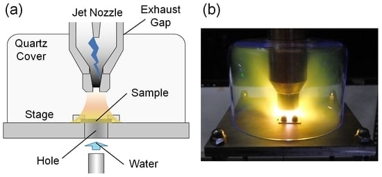
Experiments were performed with the PA plasma jet system shown in
Figure 1a. The jet nozzle was composed of coaxial cylindrical electrodes. The grounded external electrode measured 35 mm in inner diameter. The discharge gap was approximately 20 mm. The nitrogen/hydrogen gas mixture was introduced into the nozzle at the total flow rate of 20 slm, where the hydrogen fraction, and the ratio of hydrogen flow rate to total flow rate, was
fH2. The low-frequency voltage pulse (5 kV in height and 21 kHz in repetition) was applied to the inner electrode, resulting in the maximum of the discharge current of ca. 1.2 A. The afterglow of the generated PA plasma was spewed out from the orifice and was 4 mm in diameter, forming the jet plume containing NH radicals.
For the spectroscopic experiment, the jet nozzle was fitted with a quartz pipe (30 mm in diameter and 500 mm in length) at the tip as shown in
Figure 1b to observe the jet plume generating in the operating gas. The optical emission of NH (A
3Π–X
3Σ
−) of 336 nm was detected with a spectrometer (Shamrock SR-500i, Andor, Belfast, UK). We collected the light emitted from the jet plume at the distance of 10 mm from the nozzle tip.
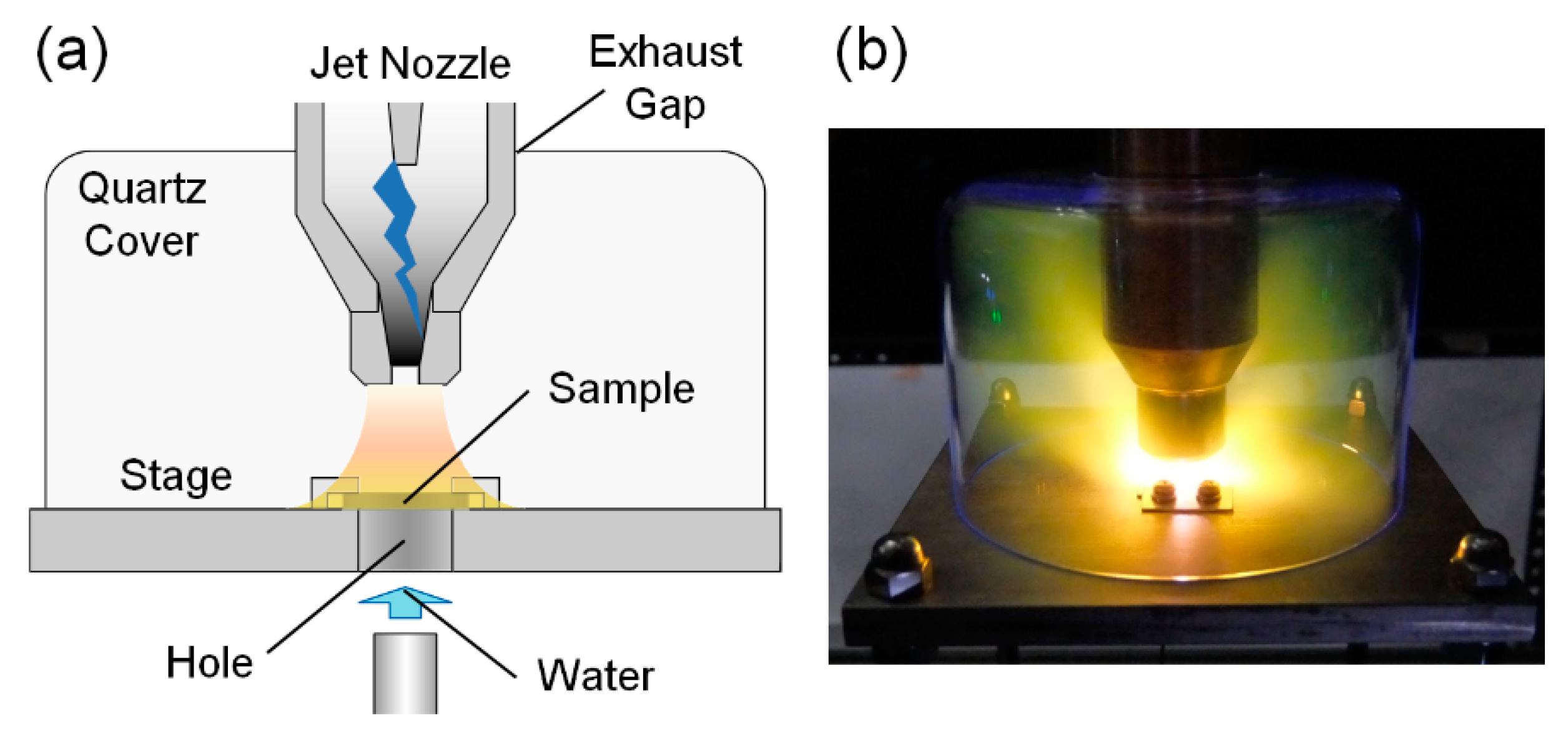
For the nitriding experiment, the jet nozzle was inserted into a cylindrically shaped cover made of quartz as shown in
Figure 2 to purge residual oxygen from the treatment atmosphere. The height and diameter of the quartz cover was 85 and 124 mm, respectively. The gas was exhausted through the 1-mm gap between the jet nozzle and the quartz cover. The experimental system was put in a simple booth (1.0 × 1.2 × 1.8 (height) m
3) surrounded by a vinyl curtain to lead the exhaust gas to the gas-treatment equipment. Prior to generating the plasma jet, residual oxygen inside the cover was gas-purged by the operating gas introduced through the nozzle.
The steel to be treated was cold roll steel JIS SPCC. The composition was as follows: 0.02% C, 0.09% Mn, 0.017% P, 0.004% S, and the balance was Fe. The sample dimension was 25 × 25 × 1.2 mm3. The hardness of base material was ca. 150 HV. The surface was mirror finished with alumina powder (1 µm) and degreased in an ultrasonic acetone bath.
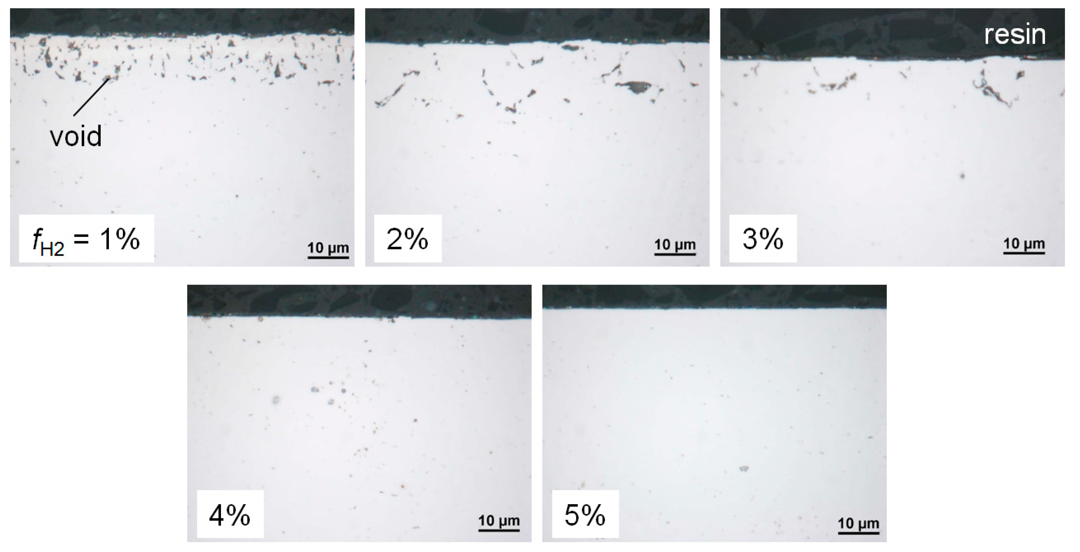
To make the effects of nitrogen dose amount as conspicuous as possible, the surface temperature was set into the range of 1000 to 1100 K during nitrogen doping and the doped sample was immediately quenched to invoke iron-nitrogen martensite transformation. Such nitro-quenching treatment was known to form voids, which can be readily observed with a microscope, in the surface when excess nitrogen was doped [
26]. In addition, the formation of iron-nitrogen martensite indicated to us the answer as to whether or not a non-trivial amount of nitrogen had been doped even when the nitrogen dose amount was intently reduced to suppress the formation of voids. The surface temperature of ca. 1000–1100 K was maintained by the plasma-jet spraying itself, where the distance between the nozzle tip to the surface was set to 7 mm. The treatment temperature was measured by spraying the jet plume to a dummy sample with a thermocouple on the surface. The doping duration was 900 to 1800 s. The doped steel was quenched by water cooling, where tap water was poured onto the opposite surface through the hole bored in the center of the sample stage.
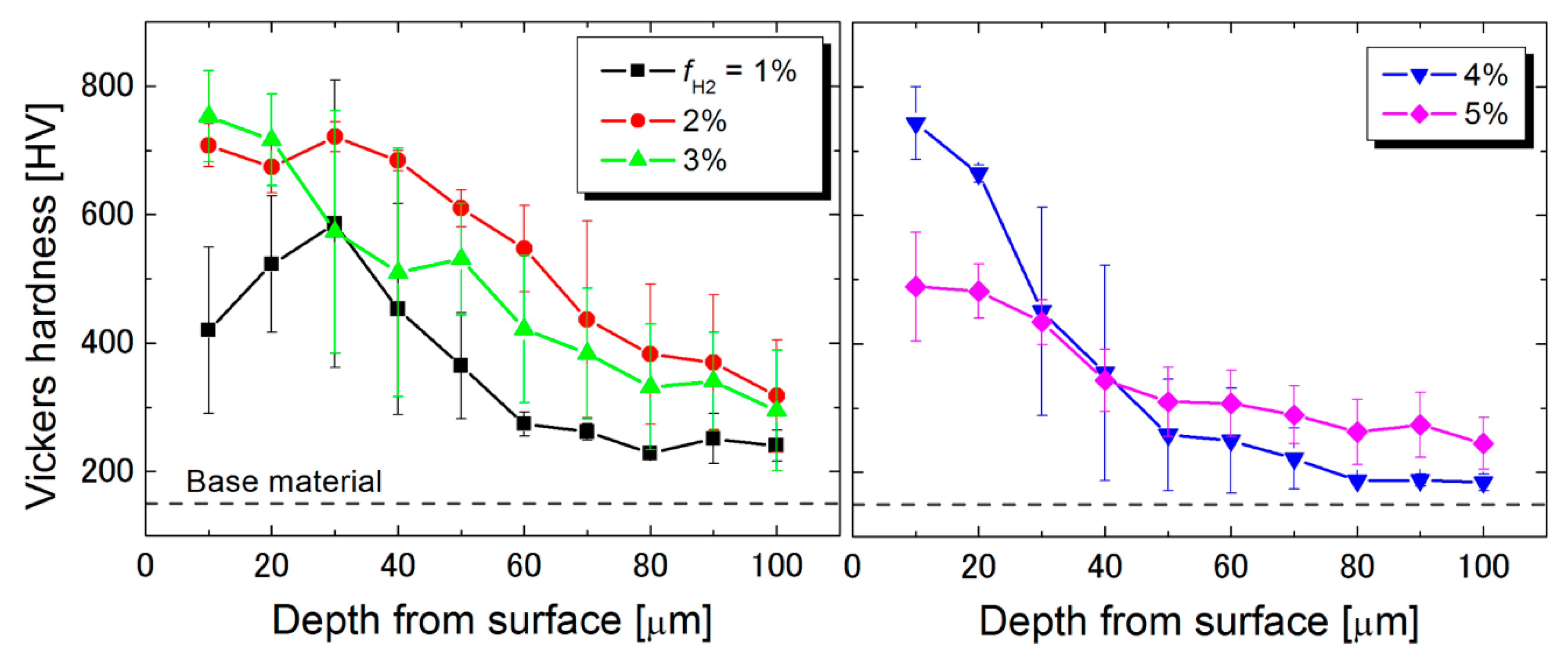
The doped nitrogen concentration in the steel surface was detected by an electron probe micro analyzer (EPMA, JXA-8200SP, JEOL, Tokyo, Japan). The void formation and the metallographic structure were observed with an optical microscope (VHX-5000, KEYENCE, Osaka, Japan) to a cross-section of doped steel surface. The sample surface was etched in nital solution (3%) for observing the metallographic structure. The formation of iron nitrides was detected by X-ray diffraction (XRD, SmartLab, Rigaku, Tokyo, Japan) using Co Kα radiation (λ = 0.179 nm). The hardness profile of the cross-section was measured with a Vickers microhardness tester (FM-300, FUTURE-TECH, Kawasaki, Japan), where the indenter load was 0.098 N and the loading time was 10 s.
Author Contributions
Conceptualization, all; data curation, R.I., M.K. and Y.K., methodology, R.I., M.K. and Y.K.; investigation, R.I., M.K., Y.K., T.O. (Takeru Okada), T.O. (Tatsuro Onomoto), K.T., T.F. and S.K.; writing—original draft preparation, R.I.; writing—review and editing, K.T. and S.K.; visualization, M.K., Y.K., T.O. (Takeru Okada), T.O. (Tatsuro Onomoto) and T.F.; supervision, R.I.; project administration, R.I.; funding acquisition, R.I.
Funding
This work was supported by JSPS KAKENHI Grant Number 15K17482.
Acknowledgments
We wish to acknowledge valuable discussions with Masahiro Okumiya, Toyota Technological Institute, and Nobuyuki Kanayama, Santier Giken Co., Ltd. We are grateful to Masaki Sonoda, Oita Industrial Research Institute, for their technical assistance.
Conflicts of Interest
The authors declare no conflicts of interest.
References
- Sun, Y.; Bell, T. Plasma surface engineering of low alloy steel. Mater. Sci. Eng. 1991, 140, 419–434. [Google Scholar] [CrossRef]
- Czerwiec, T.; Michel, H.; Bergmann, E. Low-pressure, high-density plasma nitriding: Mechanisms, technology and results. Surf. Coat. Technol. 1998, 108–109, 182–190. [Google Scholar] [CrossRef]
- Rie, K.-T. Recent advances in plasma diffusion processes. Surf. Coat. Technol. 1999, 112, 56–62. [Google Scholar] [CrossRef]
- Li, C.X. Active screen plasma nitriding—An overview. Surf. Eng. 2010, 26, 135–141. [Google Scholar] [CrossRef]
- Nishimoto, A.; Tanaka, T.; Matsukawa, T. Effect of surface deposited layer on active screen plasma nitriding. Mater. Perform. Charact. 2016, 5, 386–395. [Google Scholar] [CrossRef]
- Nishimoto, A.; Matsukawa, T.; Nii, H. Effect of screen open area on active screen plasma nitriding of austenitic stainless steel. ISIJ Int. 2014, 54, 916–919. [Google Scholar] [CrossRef]
- Marcos, G.; Guilet, S.; Cleymand, F.; Thiriet, T.; Czerwiec, T. Stainless steel patterning by combination of micro-patterning and driven strain produced by plasma assisted nitriding. Surf. Coat. Technol. 2011, 205, S275–S279. [Google Scholar] [CrossRef]
- Aizawa, T.; Morita, H.; Wasa, K. Low-temperature plasma nitriding of Mini-/Micro-tools and parts by table-top system. Appl. Sci. 2019, 9, 1667. [Google Scholar] [CrossRef]
- Michel, H.; Czerwiec, T.; Gantois, M.; Ablitzer, D. Progress in the analysis of the mechanisms of ion nitriding. Surf. Coat. Technol. 1995, 72, 103–111. [Google Scholar] [CrossRef]
- Hudis, M. Study of ion-nitriding. J. Appl. Phys. 1973, 44, 1489. [Google Scholar] [CrossRef]
- Matsumoto, O.; Konuma, M.; Kanzaki, Y. Nitriding of titanium in an r.f. discharge II: Effect of the addition of hydrogen to nitrogen on nitriding. J. Less Common Met. 1982, 84, 157–163. [Google Scholar] [CrossRef]
- Sakamoto, Y.; Takaya, M.; Ishii, Y.; Igarashi, S. Surface modified tool fabricated by radical nitriding. Surf. Coat. Technol. 2001, 152–155. [Google Scholar] [CrossRef]
- Lee, I.; Park, I. Microstructure and mechanical properties of surface-hardened layer produced on SKD 61 steel by plasma radical nitriding. Mater. Sci. Eng. 2007, 449, 890–893. [Google Scholar] [CrossRef]
- Tamaki, M.; Tomii, Y.; Yamamoto, N. The role of hydrogen in plasma nitriding: Hydrogen behavior in the titanium nitride layer. Plasmas Ions 2000, 3, 33–39. [Google Scholar] [CrossRef]
- Tahchieva, A.B.; Llorca-Isern, N.; Cabrera, J.-M. Duplex and superduplex stainless steels: microstructure and property evolution by surface modification processes. Metals 2019, 9, 347. [Google Scholar] [CrossRef]
- Almeida, G.F.C.; Couto, A.A.; Reis, D.A.P.; Massi, M.; Da Silva Sobrinho, A.S.; De Lima, N.B. Effect of plasma nitriding on the creep and tensile properties of the Ti-6Al-4V alloy. Metals 2018, 8, 618. [Google Scholar] [CrossRef]
- Ichiki, R.; Nagamatsu, H.; Yasumatsu, Y.; Iwao, T.; Akamine, S.; Kanazawa, S. Nitriding of steel surface by spraying pulsed-arc plasma jet under atmospheric pressure. Mater. Lett. 2012, 71, 134–136. [Google Scholar] [CrossRef]
- Nagamatsu, H.; Ichiki, R.; Yasumatsu, Y.; Inoue, T.; Yoshida, M.; Akamine, S.; Kanazawa, S. Steel nitriding by atmospheric-pressure plasma jet using N2/H2 mixture gas. Surf. Coat. Technol. 2013, 225, 26–33. [Google Scholar] [CrossRef]
- Yoshimitsu, Y.; Ichiki, R.; Kasamura, K.; Yoshida, M.; Akamine, S.; Kanazawa, S. Atmospheric-pressure plasma nitriding of titanium alloy. Jpn. J. Appl. Phys. 2015, 54, 030302. [Google Scholar] [CrossRef]
- Maeda, A.; Ichiki, R.; Tomizuka, R.; Nishiguchi, H.; Onomoto, T.; Akamine, S.; Kanazawa, S. Investigation on local formation of expanded austenite phase by atmospheric-pressure plasma jet. In Proceedings of the XXXIII International Conference on Phenomena in Ionized Gases, Estoril, Portugal, 9–14 July 2017; Alves, L.L., Tejero-del-Caz, A., Eds.; p. 169. [Google Scholar]
- Sannomiya, R.; Ichiki, R.; Otani, R.; Hanada, K.; Sonoda, M.; Akamine, S.; Kanazawa, S. Investigation on hard-tissue compatibility of TiN surface formed by atmospheric pressure plasma nitriding. Plasma Fusion Res. 2018, 13, 1306120. [Google Scholar] [CrossRef]
- Chiba, S.; Ichiki, R.; Nakatani, T.; Ueno, T.; Kanazawa, S. Development of local evacuation system for inhibiting oxidization in atmospheric-pressure plasma jet nitriding. Results Phys. 2019, 13, 102131. [Google Scholar] [CrossRef]
- Miyamoto, J.; Inoue, T.; Tokuno, K.; Tsutamori, H.; Abraha, P. Surface modification of tool steel by atmospheric-pressure plasma nitriding using dielectric barrier discharge. Tribol. Online 2016, 11, 460–465. [Google Scholar] [CrossRef]
- Kitamura, K.; Ichiki, R.; Tsuru, T.; Akamine, S.; Kanazawa, S. Demonstration of nitriding by dielectric barrier discharge and investigation of treatment range controllability. In Proceedings of the 21st International Conference on Gas Discharges and their Applications, Nagoya, Japan, 11–16 September 2016; Yokomizu, Y., Kojima, H., Eds.; pp. 429–432. [Google Scholar]
- Liedtke, D. Gas Nitriding and Nitrocarburizing. In Wärmebehandlung von Eisenwerkstoffen II: Nitrieren und Nitrocarburieren; Expert Verlag: Renningen, Germany, 2014. [Google Scholar]
- Chiba, M.; Miyamoto, G.; Furuhara, T. Microstructure of pure iron treated by nitriding and quenching process. J. Jpn. Inst. Metals 2012, 76, 256–264. [Google Scholar] [CrossRef][Green Version]
© 2019 by the authors. Licensee MDPI, Basel, Switzerland. This article is an open access article distributed under the terms and conditions of the Creative Commons Attribution (CC BY) license (http://creativecommons.org/licenses/by/4.0/).

 ,
, 


