Article

The Microstructure Evolution and Mechanical Properties of TiBw/TA15 Composite with Network Structure Prepared by Rapid Current Assisted Sintering

1
National Key Laboratory for Precision Hot Processing of Metals, Harbin Institute of Technology, Harbin 150001, China
2
School of Materials Science and Engineering, Harbin Institute of Technology, Harbin 150001, China
3
Xi’an Space Engine Company Limited, Xi’an 710100, China
*
Author to whom correspondence should be addressed.
Metals 2019, 9(5), 540; https://doi.org/10.3390/met9050540
Submission received: 24 April 2019 / Revised: 5 May 2019 / Accepted: 7 May 2019 / Published: 10 May 2019
(This article belongs to the Special Issue Advances in Metal Composites and Processing Technologies)

Abstract

:
TiBw/TA15 (TA15 alloy reinforced by TiB whiskers) composites with network microstructures were successfully prepared by current-assisted sintering at 1100 °C for 10 min. The influence of the sintering parameters on the microstructures of obtained composites was investigated. The sintering temperature was the main factor affecting the average aspect ratio of TiBw, and the average diameter of TiBw could be controlled for various sintering conditions. Yield strength, ultimate compressive strength, and plastic strain at ambient temperature are 1172.5 MPa, 1818.4 MPa, and 22.4% for the TiBw/TA15 composites, respectively. Moreover, yield strength of the composites at 600 °C is 616.3 MPa, which is 26.1% higher than that of the TA15 titanium alloy. The effect of the TiBw on the microstructure evolution for the alloy matrix was discussed in detail. The strengthening mechanism of the TiBw/TA15 composites with network microstructure was attributed to the microstructure modification induced by TiBw, load bearing effect, and dislocation strengthening effect of the TiBw.

1. Introduction

Titanium and titanium alloys are widely used in the aerospace industry [1,2,3] and bio-medicine [4] because of their excellent characteristics, such as high specific strength, good high-temperature performance, excellent corrosion resistance, and good biocompatibility. However, in recent years, along with the increase of thrust:weight ratio for modern aero-engines, the service temperature of engine materials has been further promoted, which means that the traditional high-temperature titanium alloys cannot meet the requirements of high-temperature strength for engine materials. As typical metal matrix composites (MMCs), titanium matrix composites (TMCs) are becoming more attractive materials for the aerospace and automotive industries due to their improved mechanical properties and high-temperature stability. Owing to their considerable properties, isotropy, and low cost [5,6,7,8], simultaneously, the discontinuous reinforced titanium matrix composites (DRTMCs) have attracted extensive attention, especially those that are produced using in situ methods. Compared with DRTMCs, according to previous studies, the TMCs with homogeneous distribution of reinforcement usually exhibit brittleness [9]. In recent years, Huang et al. [10] have successfully fabricated a new type of TiBw/TC4 (TC4 alloy reinforced by TiB whiskers) composite with a novel network microstructure by means of low-energy powder mixing and reactive hot-pressing (RHP) to achieve a better combination of strengthening of reinforcement and of increasing toughness of the titanium alloy matrix. The research results indicate that this TMC, with a network microstructure, not only possesses the advantages of high specific strength, specific stiffness, and good high-temperature stability, but also has better comprehensive mechanical properties than the TMCs with homogeneous reinforcement distribution [10,11,12]. It is also of interest to note that the microstructure of TMCs with network morphology can change significantly [10,12]. The Ti-6Al-4V alloy [13] without TiB whiskers (TiBw) exhibits a typical widmanstätten microstructure, while the matrix of TMCs with a network microstructure consists of equiaxed α phases, α laths, and an intergranular β phase.
As for the obvious advantages of the powder metallurgy (PM) method for in situ reaction manufacturing of the TMCs with network microstructures, Zhang et al. [14] fabricated TiBw/TA15 composites using the Powder metallurgy (PM) method. The results showed that the strength and plasticity of the composites were improved when compared with those of TA15 titanium alloy. Spark plasma sintering (SPS), as a highly efficient current-assisted sintering technique, not only has the features of homogeneous composition and high material utilization ratio [15,16], but also exhibits the advantages of faster heating rate [17], shorter holding time [18], lower sintering temperature [19,20], and energy saving. To date the SPS method has been used to prepare ceramics, intermetallic compounds, nanostructured materials, metal-based composites, and other materials that are difficult to sinter by conventional methods. Recently, Sun et al. [21] successfully realized the rapid preparation of TC4 titanium alloy by SPS technique. In addition, Ti-4Fe-7.3Mo composites with uniform distribution reinforcement of TiB whiskers (TiBw) were prepared by SPS and hot-pressing (HP) sintering. Feng et al. [22,23,24] found that the size of in situ synthesized whiskers for the SPS process was larger than that of the HP process through transmission electron microscope analysis of two samples sintered at the same temperature. These results indicate that the SPS process may realize the preparation of TiBw-reinforced TMCs at a lower temperature and in a shorter time because of the effect of the sintering current.
Based on the above demonstrations, in order to further improve the service temperature of titanium alloy and achieve rapid preparation of TMCs with network microstructures, the network TiBw/TA15 composites were prepared by SPS method. The purpose of this paper is to study the densification process of the TiBw/TA15 composites with network microstructures fabricated by SPS; meanwhile, the effects of sintering parameters and TiBw on the microstructure evolution of matrix have been further investigated. Furthermore, the strengthening mechanism of TiBw/TA15 composites with network microstructures has been discussed.

2. Materials and Methods

2.1. The Initial Powders and Material Preparation

In this work, the TA15 alloy, as a typical high-temperature titanium alloy of near α-type, was chosen as the matrix of composites because of its ambient and elevated temperature strength and good thermal stability. Moreover, TiB whiskers (TiBw) produced by in situ reaction were used as reinforcement due to their high modulus and good chemical compatibility with titanium.
To prepare the TMCs with network microstructures, spherical TA15 titanium alloy powders (the chemical composition is shown in Table 1) and prismatic TiB2 powders were selected. The TA15 powders were supplied by ShanXi YuGuang Metal Materials Co. Ltd., Xi’an, China, and the TiB2 powders were produced by ZiBo Special Ceramics Ltd., ZiBo, China. The morphologies of initial powders are shown in Figure 1a,b, respectively. Then, the spherical TA15 powders and prismatic TiB2 particles (mass fraction 2.1%) were mixed by low energy milling process, and the morphology of the mixed powders is shown in Figure 1c.
Subsequently, the mixed powders were poured into the graphite die and columnar samples with a diameter of 30 mm and height of 15 mm were obtained by the in situ reaction and consolidation of the mixed powders using the SPS system. According to previous works [19,20,22,25], the mixed powders were sintered at 800–1300 °C for 60 min (providing sufficient time for in situ reaction) with a pressure of 30 MPa in a vacuum. Afterwards, the optimization of the holding time under the optimal sintering temperature of 1100 °C was carried out. The holding times were 10, 20, 30, and 45 min, while the pressure was maintained at 30 MPa. In the present work, the heating rate of 30 °C /min was introduced [26]. After heating and temperature preservation, the samples were cooled in a furnace.
In addition, in order to study the influence of TiBw on the microstructure evolution of TA15 titanium alloy and the strengthening mechanisms of TMCs with network microstructures, the TA15 alloy sample [21] was also prepared by SPS at 1100 °C for 7 min with a pressure of 50 MPa.

2.2. Microstructure Analysis and Mechanical Properties

The densities of the sintered samples were evaluated by the Archimedes’ method. The microstructures were studied by X-ray diffraction (XRD, PANalytical B.V., Almelo, The Netherlands), optical microscope (OM, Leica company, Wetzlar, Germany), scanning electron microscopy (SEM, FEI company, Hillsboro, OR, USA) and transmission electron microscope (TEM, FEI company, Hillsboro, OR, USA). The phase identification of samples was carried out by Empyrean intelligent X-ray diffraction (PANalytical B.V., Almelo, The Netherlands) using Cu Kα radiation. For the sake of metallographic observation of TA15 titanium alloy, the sample was mechanically polished and etched by the solution consisting of 7% HF, 13% HNO3, and 80% distilled water. Afterwards, the metallographic photographs of the TA15 titanium alloy were taken by a Leica optical microscope (Leica company, Wetzlar, Germany). The microstructural characterizations were also performed using a Quanta 200FEG SEM (FEI company, Hillsboro, OR, USA) and Talos F200X TEM (FEI company, Hillsboro, OR, USA). The aspect ratio (the ratio between length and diameter) and size of TiBw for samples in SEM images with different sintering parameters were counted by Nano Measure 1.2 software (Fudan University, Shanghai, China). The measurements of the width of α colony and α laths were also conducted using Nano Measure 1.2 software.
For the compression test, the samples with a diameter of 3mm and a height of 4.5 mm were machined by wire cutting along the axial direction. Prior to testing, the sample surface was polished by metallographic sandpaper (2000 sharp particles per square inch, SanYou company, Suzhou, China). The ambient temperature compression test was carried out using an AGX-plus SHIMADZU electronic universal testing machine (with an ultimate load of 20 kN, SHIMADZU Corporation, Kyoto, Japan). The elevated temperature compression properties of the TA15 titanium alloy and the composite samples were tested on the AG-X plus electronic universal testing machine (with an ultimate load of 50 kN, SHIMADZU Corporation, Kyoto, Japan). The test temperature was selected as 600 °C for TA15 titanium alloy and composites. Before the elevated temperature compression test, the samples were kept for 5 min to make the temperature uniform. The moving speed of the upper punch for the compression test was 2.7 mm/min (the corresponding strain rate was 0.01 s−1). At least three samples were used for each compression test, and the strength and plastic deformation of the samples were obtained by calculating the arithmetic mean.

3. Results

3.1. The Effect of Sintering Parameters on the Densification

The densities of samples sintered at different parameters are shown in Table 2. Comparing the densities of samples sintered at different temperatures, it was found that the density noticeably increased with the increase of temperature up to 900 °C, and then it remained almost constant thereafter in the temperature range of 900–1300 °C. The density could be considered as a function of sintering temperature, which was consistent with previous studies [27,28]. The density results indicate that the full densification of mixed powders can be achieved by SPS at 1000 °C or even 900 °C. Furthermore, comparing the density of samples sintered at 1100 °C for different holding times, there was no significant difference in the density of samples sintered at 1100 °C for 10 min and 60 min, which were 4.43 g/cm3 and 4.44 g/cm3, respectively. This result suggests that the SPS process can obtain dense samples at a holding time of 10 min, which is much shorter for the preparation of TMCs with network microstructures than in situ reactive hot pressing (RHP), as adopted by Huang et al. [29] and Zhang et al. [25,30]. According to their research results [13,25,29], the preparation of TMCs with network microstructures by RHP requires sintering at 1100 °C or higher for at least 1 h to fabricate compact samples.
Since the mixed powders had micro-gaps between the particles at the initial stage of sintering, when the current passed through the mixed powder, a high-temperature discharge plasma could be generated at the micro-gaps due to the discharge effect [18,31]. Furthermore, the surface of the mixed powders was activated, and then the impurities and oxides on the surface of the particles were cleared [32,33]. Therefore, a helpful diffusion path for the rapid densification of mixed powders was gained. Simultaneously, due to the small contact area between particles, the current density near the contact neck was relatively higher than the interior of the powders during SPS. The temperature increasing in microscopic regions of particles can be described as Equation (1) [34]:
Δ T = 16 π 2 I 2 ρ Δ t C V ρ m [ r 2 ( r x ) 2 ] 2
where the π is the Pi, CV is the heat capacity of materials, ρm is the mass density of materials, I is the local intensity of the current, ρ is the resistivity of materials, ∆t is the duration of the pulsed current, r is the radius of the particle, and x is the distance from the contacting surface between two particles.
It is noted that the temperature of the contact area between particles under the Joule effect is significantly higher than that in the interior of particles from Equation (1). Thus, the plastic deformation of the particles occurred in the contact area under the sintering pressure due to the reduced yield stress caused by local high temperature. Moreover, the current also accelerated the diffusion process between particles [18,35], which contributed to the growth of the sintering neck and made the mixed powders compact rapidly. Based on these discussions, the rapid and effective current-assisted sintering of mixed powders is mainly owing to the comprehensive effects of spark discharge, Joule heat, plastic deformation, and electric diffusion involved in SPS.

3.2. Microstructure Evolution

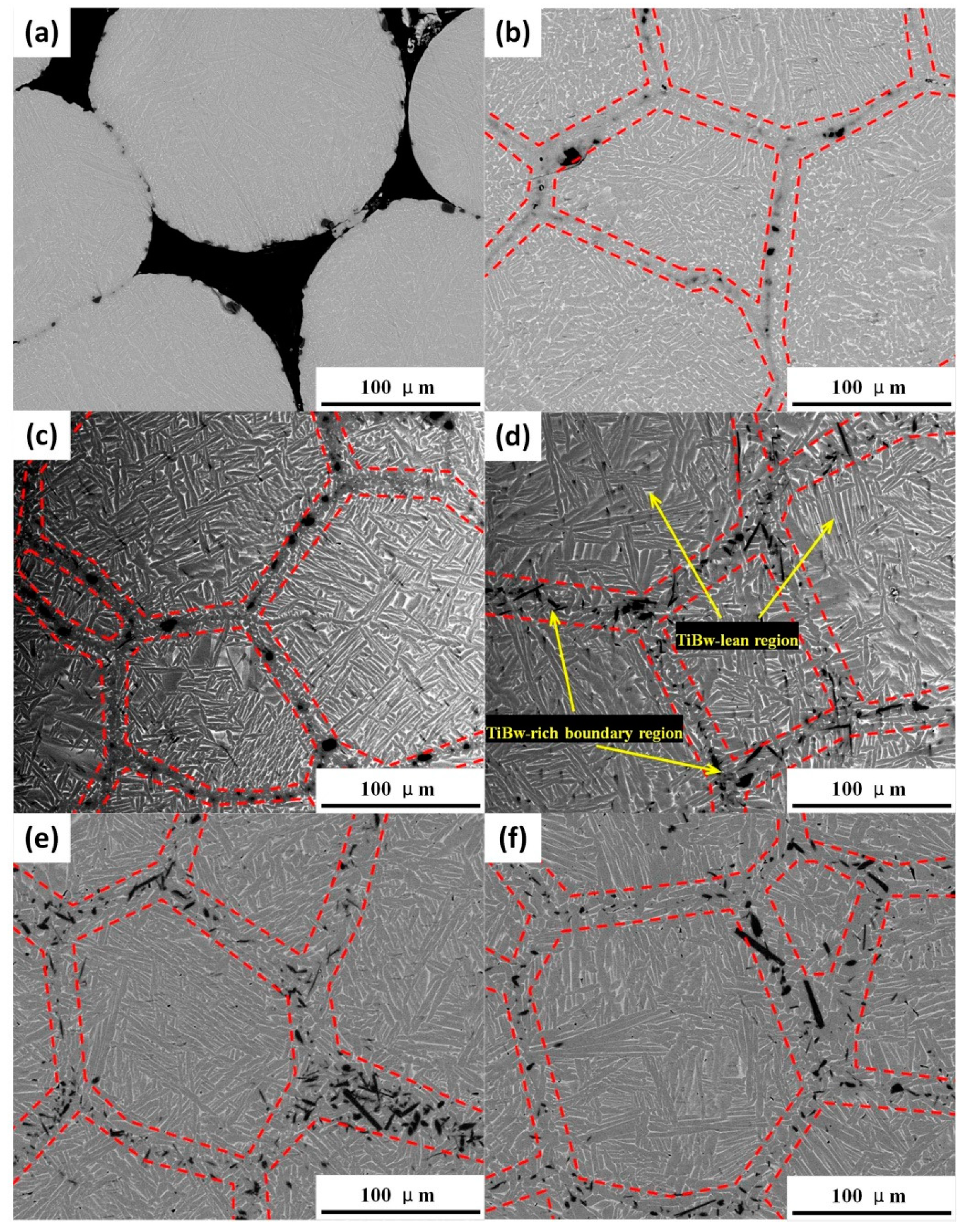
3.2.1. The Effects of Sintering Temperature on Microstructure

The XRD patterns of composites sintered at 800–1300 °C for 60 min are shown in Figure 2. The diffraction peaks of TiB appeared in all patterns, and no diffraction peaks of TiB2 were detected, which indicates that the chemical reaction between TiB2 and Ti occurred. Because the volume fraction of TiB is small and its diffraction peaks overlap with several peaks of α phase, the intensities of TiB diffraction peaks do not show obvious differences as the sintering temperature rises from 800 °C to 1300 °C. In addition, the XRD patterns also show that the matrix of the composites consists of α phase and a small amount of β phase, in addition to the TiB reinforcement.
The typical SEM micrographs of the samples sintered at different temperatures are shown in Figure 3. As can be seen, the α phase is in gray contrast in the back scattered SEM micrographs and the β phase shows bright contrast, as well as the dark TiBw reinforcement. As shown in Figure 3a, the micropores of sample sintered at 800 °C could be observed. With the sintering temperature further increased to 900 °C, the micropores disappeared in the microstructure and this result was consistent with the density measurements in Table 2. Although dense samples were obtained at 900 °C and 1000 °C, the reinforcement phase distributed in the boundary regions presented a similar particle-like morphology (Figure 3b,c). In the temperature range of 1100–1300 °C, the TiB whiskers (TiBw) were in situ synthesized at the local areas around the boundaries of TA15 powders, forming a network microstructure that can be divided into the TiBw-rich boundary region and TiBw-lean matrix region (Figure 3d). This result revealed that the TiBw/TA15 composites were successfully fabricated by SPS in the temperature range of 1100–1300 °C for 60 min. It can be also seen from the SEM micrographs that the matrix of the composites is composed of an α phase and intergranular β phase (Figure 3d–f), which is in accordance with the results of XRD patterns (Figure 2).
The TiBw synthesized at the boundary of TA15 powders is visually like a dowel, which connects the adjacent TA15 powders and thus obtains the TiBw/TA15 composites with network microstructures. Subsequently, it is essential to investigate the size of TiBw for the composites sintered at 1100–1300 °C and the distribution of the aspect ratio. In this work, the aspect ratio of TiBw can be represented by f, which can be described by the Equation (2):
f = l d
where the l is the length of the TiBw and d is the diameter of the TiBw. The average f (AF) value and average diameter of the TiB whiskers (TiBw) were determined and the results are summarized in Figure 4. It is found that the f of TiBw for the TMCs with network microstructures sintered at 1100 °C distributed within 7.5–12.5 is over 85%, as well as 10% whiskers, with f values more than 17.5 (Figure 4a). The f of TiBw for TMCs sintered at 1200 °C and 1300 °C exhibits similar distribution characteristics, which are mainly distributed in the range of 5–10 (Figure 4b,c). Moreover, it is of interest to note that the average aspect ratio (AF) decreases from 11.08 to 7.41 as the sintering temperature rises from 1100 °C to 1200 °C, and then remains nearly constant with further increases in the sintering temperature to 1300 °C. This result is consistent with the previous study carried out by Zhang et al [36]. Because TiB has the crystal structure of B27 [37], the diffusion activation energy of the B atom in the TiB crystal along the [010] direction is lower than that in the [001] direction [38]. Consequently, the diffusion of B atoms along the [010] direction is relatively easier at lower temperatures, which means the growth rate of the [010] direction to precede the [001] direction. With the increase of sintering temperature, the length of TiBw becomes larger. In order to further grow in the [010] direction, B atoms need to diffuse along the [010] direction for a longer distance, although B atoms diffuse faster in this direction. On the other hand, the diffusion distance of B atoms along [001] direction is smaller in this case, and the vacancy concentration in TiBw increases when the temperature rises. Thus, the diffusion of B atoms in the [001] direction is promoted, accelerating the growth of TiB along the [001] direction. For these reasons, the average diameter of TiBw gradually coarsens with the increase of sintering temperature from 1.73μm at 1100 °C to 2.98 µm at 1300 °C, while the f of TiBw decreases.

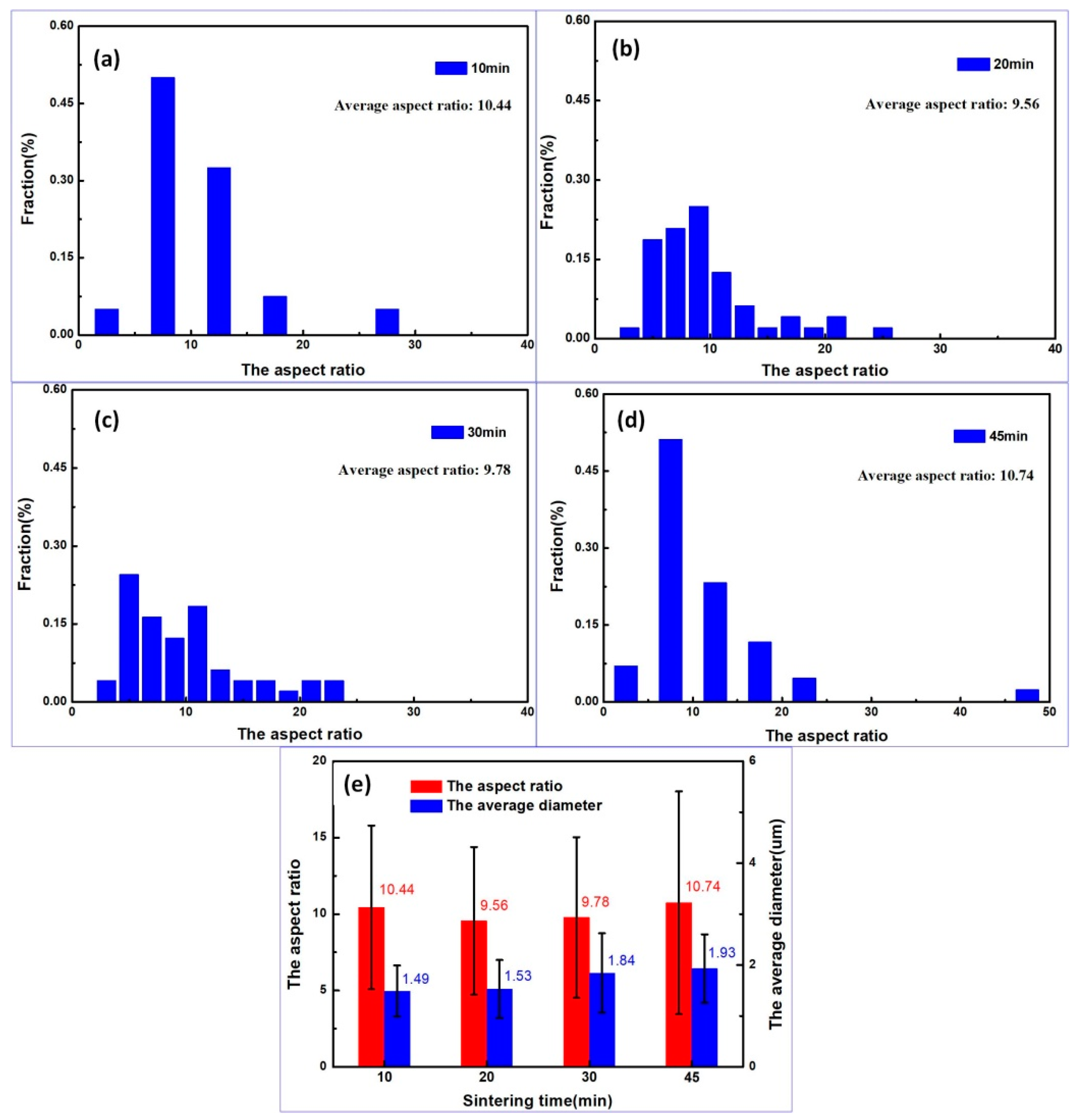
3.2.2. The Effects of Sintering Time on Microstructure

Figure 5 shows the SEM micrographs of the samples sintered at 1100 °C for different holding times. One can see that the preparation of the TiBw/TA15 composites with network microstructures can be realized by SPS sintering at 1100 °C for 10 min, as shown in Figure 5a. The network microstructure also consists of the boundary region, which has a rich reinforcement phase, and the matrix region, with a poor reinforcement phase, as marked by the yellow arrows in Figure 5a. The microstructure of the matrix is similar for the samples using different holding times (Figure 5a–d), which has the α phase and a small amount of intergranular β phase. It is also worth noting that the coarse α laths intersected each other, forming a typical basket-weave morphology in the TiBw-lean matrix region, as shown in Figure 5 and Figure 3d–f.
The average f (AF) value and average diameter of the TiB whiskers (TiBw) in the samples with different holding times were determined and the results are summarized in Figure 6. The AF of the TiBw for the TMCs with network microstructures prepared under holding times of 10 min, 20 min, 30 min, and 45 min is similar, which is different from the results at various sintering temperatures (Figure 4a–c). Moreover, the f value of most TiBws is more than 7.5, as shown in Figure 6a–d. These results suggest that the holding time affects the f of TiBw slightly (Figure 6e) when compared with the sintering temperature. With the increase of holding time, the diameter of whiskers gradually becomes coarser, indicating that the TiBw continues to grow along the directions of both 010 and 001. Based on the above results, it is noted that the size of TiBw is mainly controlled by sintering temperature and holding time. Although the holding time has an effect on the whisker diameter, it does not change the f values significantly, which is dominated by the sintering temperature.

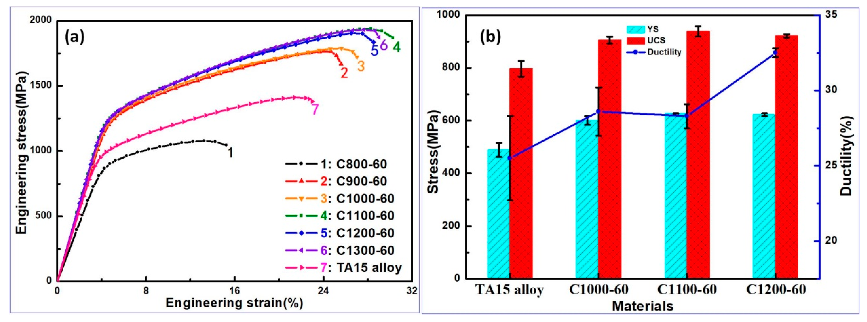
3.3. Mechanical Properties

Figure 7a shows the ambient temperature compressive engineering stress–strain curves of the samples sintered at different sintering temperatures. For comparison, the TA15 titanium alloy without reinforcement is also sintered at 1100 °C (using the notation of TA15 alloy for this sample). The obtained compressive curves at ambient temperature can be divided into four categories: (a) Curve 1 of the sample sintered at 800 °C for 60 min indicates that the density is low and there are many micropores in the material (Figure 3a); (b) Curves 2 and 3 of the samples sintered at 900–1000 °C for 60 min suggest that the composites have improved densities, but the reinforcements distributed at the grain boundary of TA15 powders are in the form of particles (Figure 3b,c); (c) Curves 4–6 represent the samples sintered at 1100 and 1300 °C for 60 min, consisting of the TiBw-rich boundary region and the TiBw-lean matrix region, which show the optimal compressive performance at ambient temperature; (d) Curve 7 is the ambient temperature compressive property of TA15 titanium alloy sintered at 1100 °C. By comparing the compressive engineering stress–strain curves at ambient temperature, it is found that the TiBw/TA15 composite with network microstructure sintered at 1100 °C for 60 min exhibits the best strengthening effect. The yield strength (YS) of C1100-60 increases from 895.6 MPa to 1204 MPa, an increase of 34.4%, and its ultimate compressive strength (UCS) also increases from 1431.1 MPa to 1921.9 MPa, an increase of 34.3% when compared with TA15 titanium alloy without reinforcement. In particular, it is worth noting that the plastic deformation also increases from 19.4% of TA15 alloy to 23.4% of C1100-60.
The elevated temperature compressive properties of the composites sintered at 1000–1200 °C for 60 min and TA15 titanium alloy were tested at 600 °C to further investigate the strengthening effects of the composites (Figure 7b). The results of the elevated temperature compressive tests show that the YS and UCS of the composite sintered at 1100 °C for 60 min are 627.4 MPa and 938.6 MPa, respectively. Furthermore, the YS values of the C1000-60 and C1200-60 samples are 600.3 MPa and 622.7 MPa, respectively. In contrast, the compressive property of the TA15 titanium alloy without reinforcement at 600 °C (Figure 7b), i.e., the YS, is 488.8 MPa, which is lower than those of the composites. Compared with the TA15 titanium alloy (UCS of 796.6 MPa), the UCS of the C1100-60 sample has been increased by 17.8%. In particular, the plasticity of composites also increased slightly compared with the value of 25.5% for TA15 titanium alloy, to 28.6%, 28.3%, and 32.5%, respectively. According to above results, one can see that the C1100-60 sample exhibits good ambient temperature and high-temperature performances, indicating that the strengthening effects of the composites provide an effective route for enhancing the service property and temperature of TA15 titanium alloy.
The ambient temperature compressive engineering stress–strain curves of the samples sintered at 1100 °C for different holding times and TA15 titanium alloy are shown in Figure 8a. From the curves of ambient temperature compression, it can be seen that the properties of the TiBw/TA15 composites with network microstructures prepared under different holding times have no obvious differences, and their YS values are approximately 1170MPa. The results of compression at ambient temperature further confirm the observation of alike microstructures (Figure 5) and it also suggests that the preparation of TiBw/TA15 composites can be realized by current-assisted sintering process at 1100 °C for 10 min. Furthermore, the results of compressive tests at elevated temperature also show the similar properties of the composites with different holding times (Figure 8b). The YS value of C1100-10 sample at 600 °C reaches 616.3 MPa, which is 26.1% higher than that of the TA15 titanium alloy. The UCS values of the composites are approximately 900 MPa at 600 °C, while the UCS value of TA15 titanium alloy is only 796.6 MPa. The plastic deformations of the composites prepared using holding times of 10, 20, 30, 45, and 60min are 33.1%, 34.3%, 33.9%, 34.0%, and 28.3%, respectively, which are still larger than that of TA15 titanium alloy (25.5%). The above results show that the rapid fabrication of TiBw/TA15 composites with network microstructures can be achieved by rapid SPS process and the service properties of titanium alloys can be further improved.

4. Discussion

4.1. Effect of in situ Reinforcement on Microstructural Evolution

Figure 9a–e shows the OM micrographs and SEM micrographs of TA15 titanium alloy and TiBw/TA15 composites sintered at 1100 °C, respectively. A colony microstructure is typically observed in the case of near-α type titanium alloys when cooled from above the β-transus temperature at a slow cooling rate, as marked by a red dotted arrow in Figure 9b. As shown in the high magnification SEM micrograph of Figure 9c, the α laths are parallel with each other and located in the same α colony. Under this situation, the widmanstätten α laths belonging to the same crystallographic variant clustered into colonies (abiding specific Burger’s orientation relationships between α and β phases). In contrast, the microstructures of TiBw/TA15 composites show tremendous differences, as shown in Figure 9d–e. The results of SEM micrographs indicate that the TiBw synthesized by in situ reaction at the boundaries of TA15 powders plays an important role in affecting the microstructure of the matrix.
Based on the above observations, the evolution of the microstructure is mainly manifested in the following aspects. Considering the network units (surrounded by the TiBw-rich boundary) as high temperature initial β grains, in this study, it was found that the size of high-temperature initial β grains of the TA15 titanium alloy was ~424.8 ± 141.2 μm, as marked by a red dotted circle in Figure 9a, while that of the TiBw/TA15 composites with network microstructures was ~140um (marked in Figure 3d–f and Figure 5a–d). In addition, the continuous grain boundary α-layers can be seen clearly from the high magnification SEM micrograph of TA15 titanium alloy in Figure 9c. On the other hand, there are equiaxed α phases in the rich-TiBw boundary regions for the TiBw/TA15 composites, as shown in the high magnification SEM micrograph of Figure 9e. This agrees with the microstructure characteristics observed in TiBw/TC4 composites reported by Huang [13] and Hill et al. [39]. Moreover, there are obvious differences in the microstructure between the lean-TiBw matrix regions of the composite and the TA15 titanium alloy. In the present work, the matrix of this composite consists of coarse α laths intersected with each other, which looks like typical basket-weave structures (marked by the black dotted circle in Figure 9d) and the small sized α colony (marked by the red dotted circle in Figure 9d). Figure 9f shows the width of the α colony and α laths, which are located in the α colony of the TA15 titanium alloy and TiBw/TA15 composites. One can see that the width of the α colony in the TiBw/TA15 composites reduces from 102.5 μm to 17.1 μm compared with the TA15 titanium alloy. In addition, the width of the α laths increases from 1.13μm for TA15 titanium alloy to 2.58 μm for the composite.
Figure 10 shows the diagram of the microstructure evolution for the composite in this work. During the heating process of SPS, the phase transition of α→β in the matrix occurred, especially when the temperature reached the β single-phase region. At high temperature, the boundary of the β grains moved rapidly, making the high-temperature initial β grains coarse. Compared with TA15 titanium alloy, there are a large number of in situ synthesized TiBw in the boundaries of the network microstructure for TiBw/TA15 composites. As the temperature rises, these TiBw would pin the movement of the high temperature β grain boundaries [40], which effectively inhibits the coarsening of high-temperature β grains to ~140μm for high-temperature initial β grains for the composite versus ~424.8 ± 141.2μm for TA15 titanium alloy, as shown in Figure 10a. According to previous study [41], this refinement of high-temperature initial β grains can also contribute to further regulation of the microstructure, especially in refining the size of the α colony.
Since the high-temperature β grain boundaries are pinned by the reinforcements (Figure 10a), these TiBw can act as the nucleation agents, and thus the energy requirements for equiaxed primary α phase formation can be easily met during the cooling process of TiBw/TA15 composites. In this situation, the equiaxed α phase nucleates depending on the TiBw, as shown in Figure 10b. This result is also confirmed by the TEM image in Figure 11a. As can be seen, the equiaxed α phase nucleates and grows on the TiBw (Figure 11a,b).
With further decrease in temperature, the primary equiaxed α phase and some of TiBw become the nucleating sites for the secondary α laths. The secondary α laths form and grow into the alloy matrix, resulting in a typical basket-weave structure, as marked by dotted circles shown in Figure 10c. Based on TEM observation (Figure 11a), one also can see the secondary α laths precipitate near the primary equiaxed α phase. Then, the remaining β phase transforms into the β-transformation structure, as shown in Figure 10d and Figure 11c, which causes the existence of small sized α colonies in the matrix. It is also noted that these small size α colonies are composed of α laths and an intergranular β phase.

4.2. The Strengthening Mechanism of TiBw/TA15 Composites

Comparing the experimental results of ambient and elevated temperature compressions, it can be seen that the TiBw/TA15 composites with network microstructures exhibits better comprehensive mechanical properties than TA15 titanium alloy. To understand this, it is suggested that the following mechanisms contribute to the strengthening of the composites.

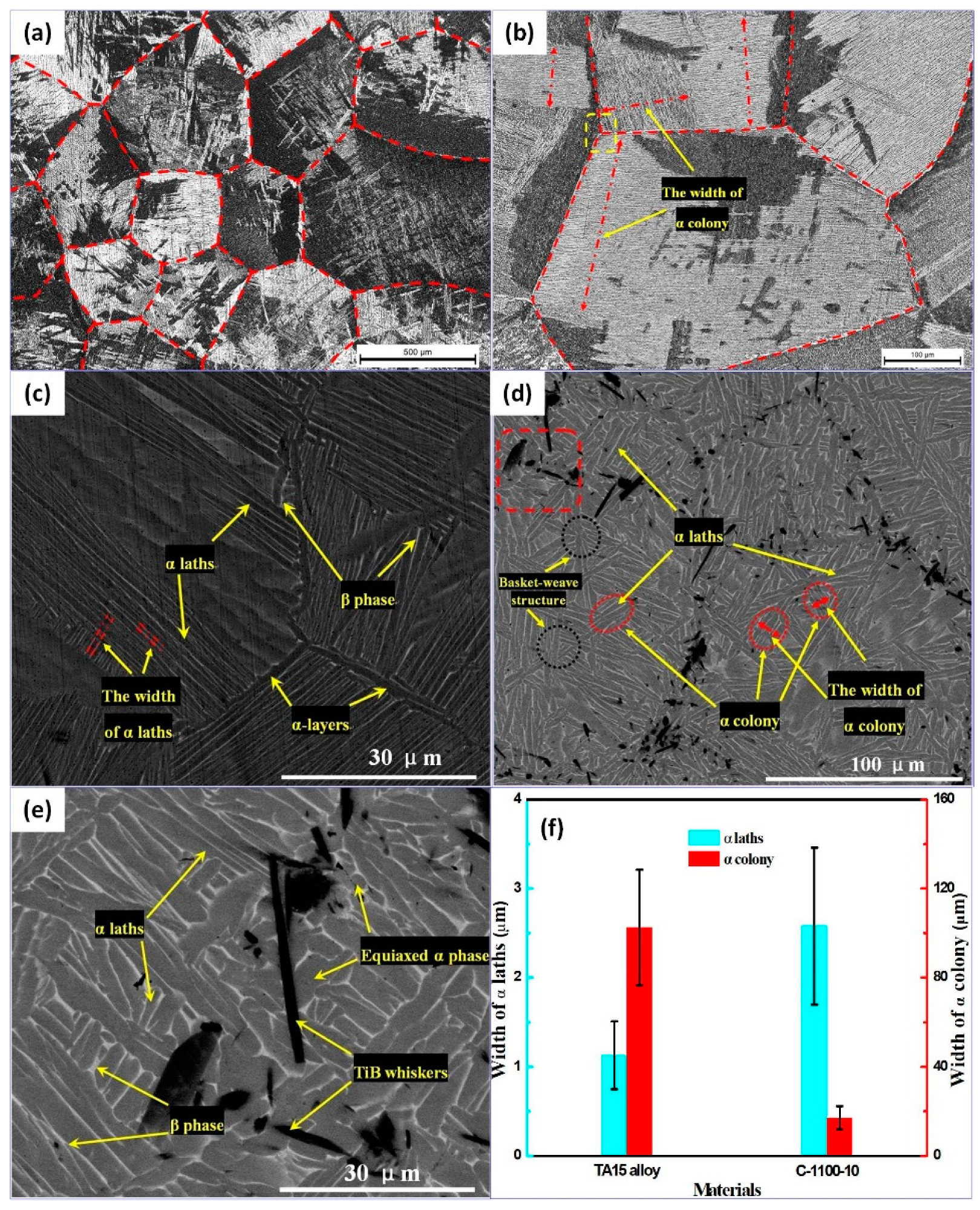
4.2.1. Effect of matrix microstructure Evolution on Mechanical Properties

The TiBw distributed around the TA15 titanium alloy powders grow towards the inside of neighboring Ti powders like dowel pins, as shown in Figure 9e. The TiBw reinforcements do not form the “closed-shell” structure, which destroys the connectivity of the matrix. Therefore, the interpenetrating matrix and TiBw-lean regions remain in the TiBw/TA15 composites (Figure 3d–f and Figure 5b–d), which provides a good ability for the composites to bear strain and blunt cracks effectively. In this situation, the composites with network microstructures can exhibit considerable plasticity.
In addition, the TiBw synthesized in situ at boundaries of TA15 powders inhibits the growth of high-temperature initial β grains, resulting in the descending size of the α colony in the composite matrix (reducing from 102.5 μm to 17.1 μm, as shown in Figure 9f). Compared with the TA15 titanium alloy, moreover, the size of α laths located in α colonies increases from 1.13 μm to 2.58 μm (Figure 9f). Because the parallel α laths in the same α colony have the same habit plane in the titanium alloy, dislocations can pass through the α colony without hindrance, causing serious dislocation pile-up at the edge of the α colony and continuous α-layers, as shown in Figure 12a. Then, the inhomogeneous micro-deformation is induced, promoting the generation of microcracks, as marked by the yellow arrows in Figure 12a. Comparatively, there are small-sized α colonies for the composites composed of coarser α laths, as shown in Figure 9f and Figure 10d. This microstructure can reduce the effective slip length of dislocations when they pass through the α colony. Meanwhile, there are some basket-weave structures formed by the α laths, which intersect each other around the α colony for the composites (Figure 9d and Figure 10c). Due to the variations of orientation between the α colony and α laths with a basket-weave structure, this basket-weave structure will serve as a strong obstacle to the dislocations, which will pile up at the edge of the basket-weave structure, as shown in Figure 12b. Thus, the dislocation pile-up in the front of α colony will be relatively weakened, leading to reduced inhomogeneous micro-deformation and less microcracks. Moreover, the equiaxed α phases exist at the network microstructure boundary of TiBw/TA15 composites rather than the continuous α-layers distributed at the high-temperature initial β grain boundary in the TA15 titanium alloy. Since there is no specific orientation relationship between the equiaxed α phase and matrix, it is easier for the dislocations to slip through optional planes in the equiaxed α phase at the boundary regions when the dislocations pile up in front of the equiaxed α phase, as shown in Figure 12b. As a result, the coordinated deforming ability of the composites at the boundary is improved by the existence of the equiaxed α phase. The above-mentioned multiple dislocation slip is beneficial for achieving considerable plasticity of the composites.
On the other hand, phase interfaces with various orientations exist around the α colony for the microstructure of the composites. Under these circumstances, more stress is required for the further movement of dislocations accumulated in composites. Particularly, these interfaces can also effectively hinder the propagation of microcracks once induced by the dislocation pile-up compared with the microstructure of the TA15 alloy (Figure 9a–c). Thus, the small-sized α colony morphology surrounded by the basket-weave structure also contributes to improving the strength of the matrix material, in comparison with the Widmanstätten microstructure of TA15 titanium alloy.

4.2.2. Effect of in situ Reinforcement on Mechanical Properties

Figure 13 shows the typical TEM micrograph of TiBw at the transverse section and the high resolution transmission electron microscope image of the TiBw/α-phase interface. One can see that the transverse section of TiBw is a hexagonal shape. Furthermore, there are no brittle phases, such as oxidation and the intermetallic compound between the TiBw/α-phase interfaces, as shown in the Figure 13c. This result further confirms the good bonding between TiBw and the matrix, which forms in the SPS process. Meanwhile, the clean and well-bonded interfacial microstructures also provide a premise for exerting the strengthening effect of the reinforcement phase. As mentioned above, the TiBw with dowel-like structures grew into the neighboring TA15 powders and formed the network microstructure. These observations indicate that the reinforcements can bear loads, and it is important to note that the load-bearing effect of TiBw in mechanical strength is mainly dependent upon the shape and volume fraction.
Based on the above discussion, the yield strengths of the composites can be analyzed using the shear-lag model [42], and the shape characteristics of TiBw are reflected by the f value in this model, as in the following Equation:
σ cy = σ my ( 1 + 1 2 f V R )
where σcy is the yield strength of composite, σmy is the yield strength of TA15 titanium alloy, and VR is the volume fraction of reinforcement. In the present work, it is assumed that the reinforcements distributed in the matrix are arranged orderly in three dimensions. Since the volume fraction of reinforcement for the composites with network microstructures is constant, according to the shear-lag model, the σcy is mainly determined by the value of f. Furthermore, According to Kelly’s theory [43], a critical whisker aspect ratio exists. The TiBws with the f exceeding the critical value play an important role in strengthening the composite. Generally, the critical whisker aspect ratio l/d can be expressed by Kelly’s Equation:
( l d ) c = σ f 2 τ i
where τi is the shear strength of the interface and σf is the shear strength of TiBw in this paper. As can been seen from the Figure 13c, the interfacial regions between the TiBw and α-phase are clean and the interface is well bonded. Therefore, τi will be limited by the shear strength of the TA15 matrix. In this circumstance, the value of τi can be approximately set to σmy 895.6 MPa for further investigation. Meanwhile, the σf is ~3500 MPa for TiBw. The value of the critical whisker aspect ratio for the TiBw/TA15 composites is ~1.95, derived from Equation (4). This result suggests that the TiBws with f values above 1.95 can possess an effective strengthening effect for the TiBw/TA15 composites. As shown above, the composites prepared at 1100 °C for different holding times exhibit similar mechanical properties due to the similar AF of TiBw in these composites (Figure 6e and Figure 8), which is consistent with Equation (3), derived from the shear-lag model. However, although the AF of TiBw decreases with the increase of sintering temperature (Figure 4d), the strength of the composites does not differ significantly (Figure 7). To understand this, it is noted that the f values of TiBw in the samples sintered at 1100, 1200, and 1300 °C are 11.08, 7.41, and 7.40, respectively. One can see that the values of AF for these composites are obviously much larger than the critical f (~1.95). As a result, an effective strengthening effect of TiBw in these composites can be achieved, leading to similarly improved strength for these three composites, compared with TA15 alloy. The above results also indicate that the TiBw could exhibit a similar strengthening effect for the composites when the obtained AF of TiBw is evidently higher than the critical value.
In addition, the TiBw distributed at the network microstructure boundary also hinders the movement of dislocations, in addition to transferring the load. In this case, the strengthening effect induced by TiBw is attributed to dislocation strengthening. The Orowan model [44], which is based on the following equation, is used to calculate the yield strength increase caused by dislocation strengthening:
Δ σ Orowan = 0.13 G m b d p [ ( 1 2 V R ) 1 3 1 ] ln ( d p 2 b )
where ΔσOrowan is the yield strength increase, Gm is the shear modulus of matrix, b is the Burgers vector of the matrix, and dp is the average particle size of the reinforcement. Since the VR, Gm, and b are constant in Equation (5), the strengthening effect caused by dislocation mainly depends on the particle size of the reinforcement and the spacing between the reinforcements. According to Orowan dislocation hindrance theory, when the volume fraction of the reinforcement phase is fixed, the larger particle size or the larger reinforcement spacing will result in a relatively weaker strengthening effect. Although the sizes of TiB whiskers in the composites prepared by SPS are relatively larger in this work, the TiBw-rich boundary region is formed due to its special spatial distribution characteristics (reinforcement phase mainly distributes at the boundaries of TA15 powders). In this reinforcement-rich region, the movement of dislocations can be effectively hindered, which is also helpful in increasing the strength.

5. Conclusions

The following conclusions are drawn from the present work:
(1)
TiBw/TA15 composites possessing excellent mechanical properties have been successfully fabricated by rapid current-assisted sintering at 1100 °C for 10 min. The density of this sample is 4.43 g/cm3. Meanwhile, the YS values of the composites at ambient temperature and 600 °C are 1172.5 MPa and 616.3 MPa, respectively.
(2)
The sintering temperature is the main factor affecting the aspect ratio of TiBw. The average aspect ratios of TiBw obtained at 1100 °C, 1200 °C, and 1300 °C are 11.08, 7.41, and 7.40, respectively. The effect of holding time on the average aspect ratio of TiBw is not evident.
(3)
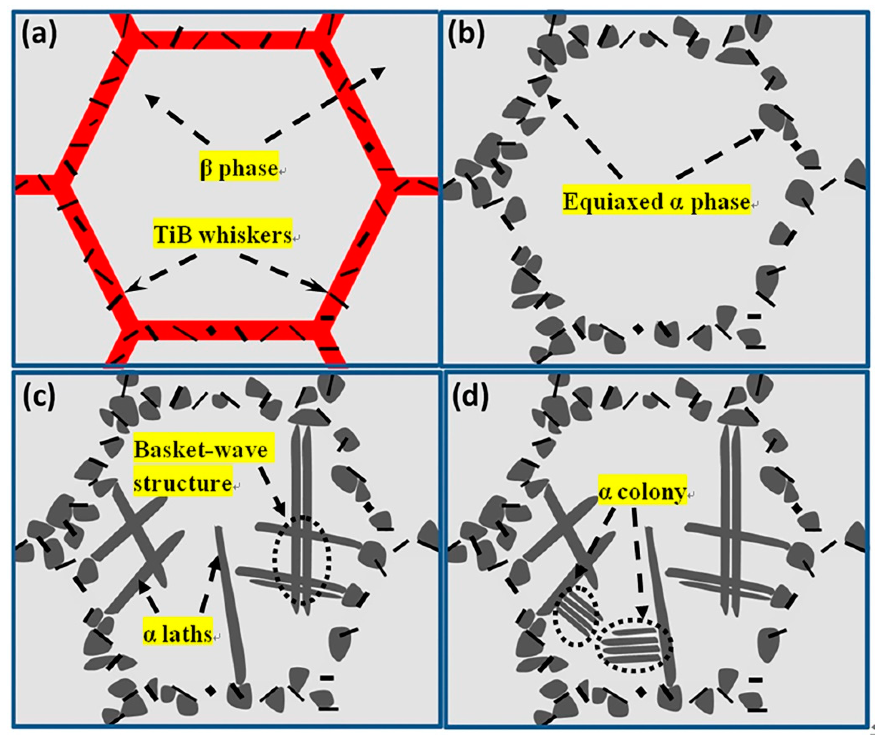
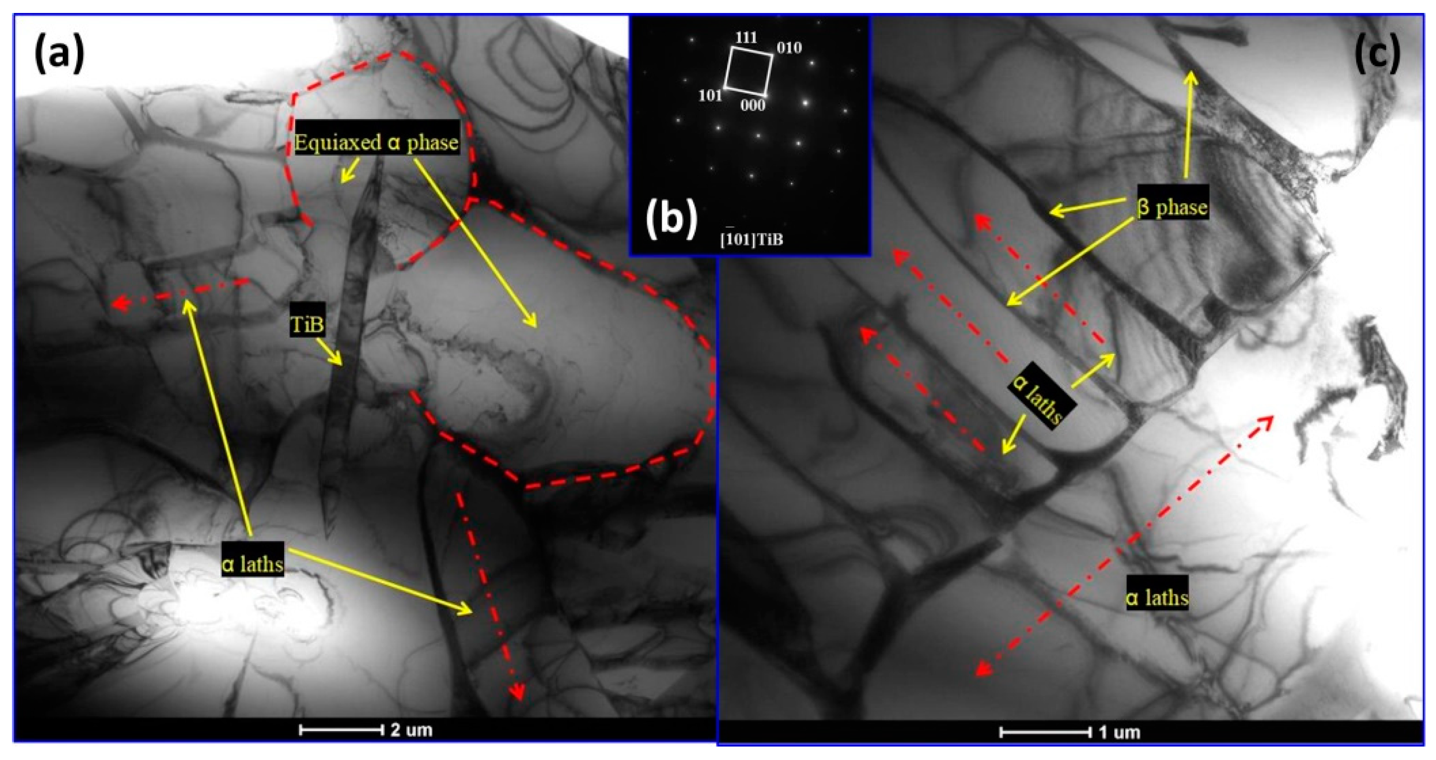
The influence of TiBw on the modification of the microstructure for the titanium alloy matrix is mainly manifested in the following aspects: (a) the high-temperature initial β grains of TA15 titanium alloy are refined from ~424.8 μm to ~140 μm, (b) providing effective nucleation sites for the equiaxed α phase, and (c) refining the width of the α colony from 102.5μm of TA15 titanium alloy to 17.1μm of TiBw/TA15 composites when sintered at 1100 °C.
(4)
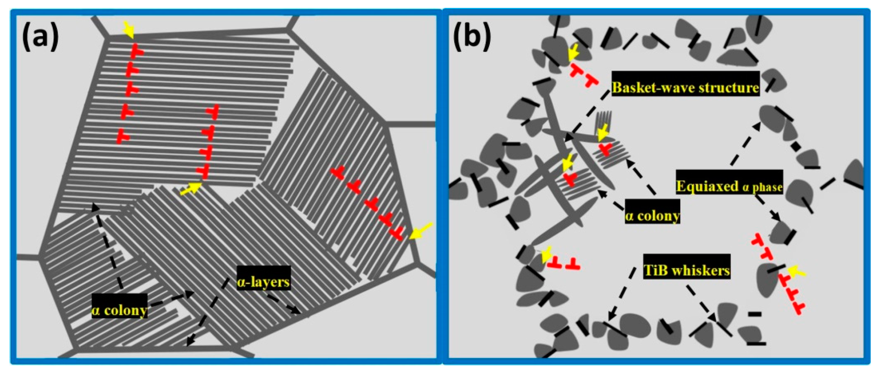
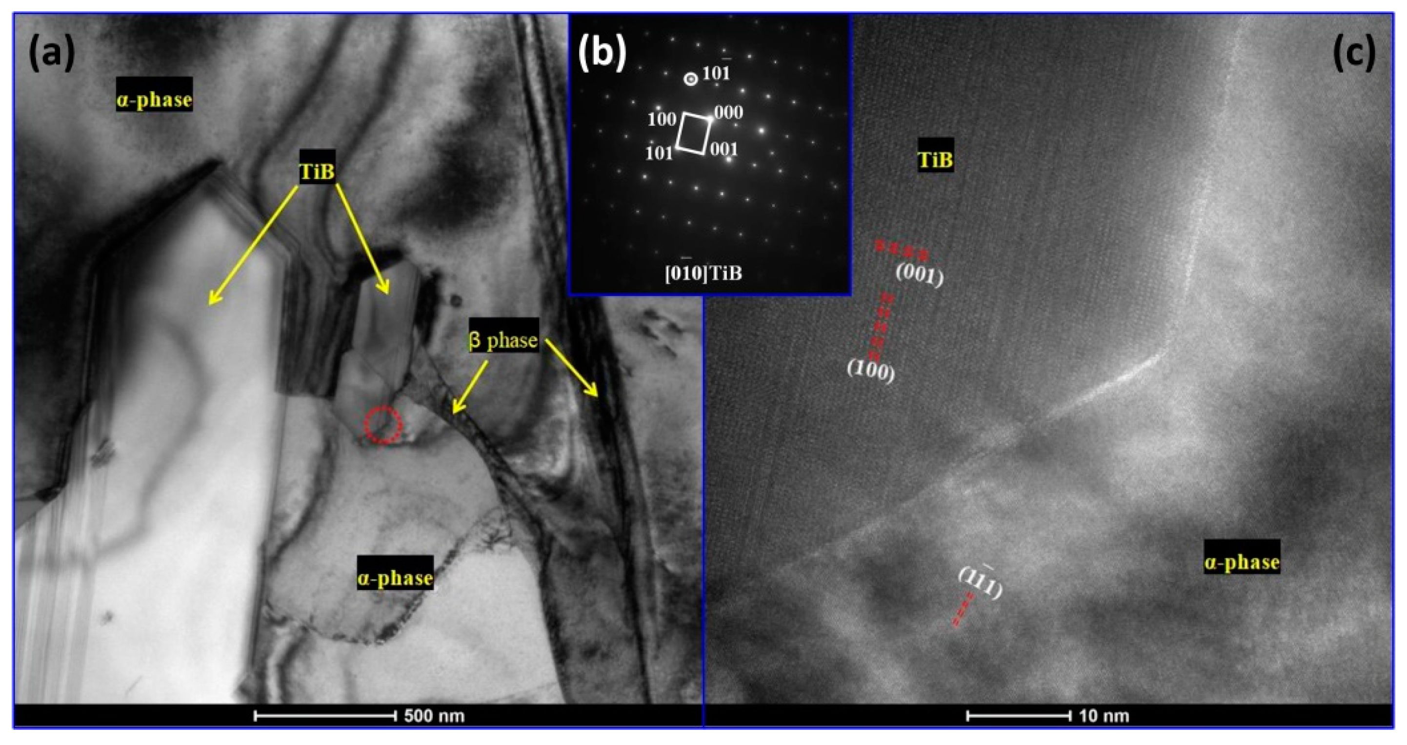
Besides the modification of the microstructure induced by TiBw, the TiBw/TA15 composites with network microstructures exhibiting better mechanical properties than TA15 titanium alloy, which is also attributed to the load-bearing and dislocation strengthening effects of TiBw. Moreover, TiBw exhibits similar strengthening effects as the average aspect ratio of TiBw exceeds the critical value (~1.95).

Author Contributions

D.W. conceived and designed the experiments. D.W. edited the paper. H.L. performed the experiments and wrote the draft paper. X.W. helped analyze the data. W.Z. helped to arrange experimental and other resources. Z.L. helped to search literature and collect the data. G.L. was in charge of the project administration.

Acknowledgments

The authors would like to thank the financial support from the National Natural Science Foundation of China (Nos. 51674093 and 91860122).

Conflicts of Interest

The authors declare no conflict of interest.

References

  1. Khanna, N.; Davim, J.P. Design-of-experiments application in machining titanium alloys for aerospace structural components. Measurement 2015, 61, 280–290. [Google Scholar] [CrossRef]
  2. Williams, J.C.; Starke, E.A., Jr. Progress in structural materials for aerospace systems. Acta Mater. 2003, 55, 5775–5799. [Google Scholar] [CrossRef]
  3. Singh, P.; Pungotra, H.; Kalsi, N.S. On the characteristics of titanium alloys for the aircraft applications. Mater. Today Proc. 2017, 4, 8971–8982. [Google Scholar] [CrossRef]
  4. Gao, A.; Hang, R.Q.; Bai, L.; Tang, B.; Chu, P.K. Electrochemical surface engineering of titanium-based alloys for biomedical application. Electrochim. Acta 2018, 271, 699–718. [Google Scholar] [CrossRef]
  5. Ma, Z.Y.; Tjong, S.C.; Gen, L. In-sit Ti-TiB metal-matrix composite prepared by a reactive pressing process. Scr. Mater. 2000, 42, 367–373. [Google Scholar] [CrossRef]
  6. Grützner, S.; Krüger, L.; Radajewski, M.; Schneider, I. Characterization of In-Situ TiB/TiC Particle-Reinforced Ti-5Al-5Mo-5V-3Cr Matrix Composites Synthesized by Solid-State Reaction with B4C and Graphite through SPS. Metals 2018, 8, 377. [Google Scholar] [CrossRef]
  7. Indrani, S.; Tamirisakandala, S.; Miracle, D.B.; Ramamurty, U. Microstructural effects on the mechanical behavior of B-modified Ti-6Al-4V alloys. Acta Mater. 2007, 55, 4983–4993. [Google Scholar]
  8. Han, J.C.; Lü, Z.D.; Zhang, C.J.; Zhang, S.Z.; Zhang, H.Z.; Lin, P.; Cao, P. The Microstructural Characterization and Mechanical Properties of 5 vol.% (TiBw + TiCp)/Ti Composite Produced by Open-Die Forging. Metals 2018, 8, 485. [Google Scholar] [CrossRef]
  9. Huang, L.J.; Xu, H.Y.; Wang, B.; Zhang, Y.Z.; Geng, L. Effects of heat treatment parameters on the microstructure and mechanical properties of in situ TiBw/Ti6Al4V composite with a network architecture. Mater. Des. 2012, 36, 694–698. [Google Scholar] [CrossRef]
  10. Huang, L.J.; Geng, L.; Peng, H.X. Microstructurally inhomogeneous composites: Is a homogeneous reinforcement distribution optimal? Prog. Mater. Sci. 2015, 71, 93–168. [Google Scholar] [CrossRef]
  11. Huang, L.J.; Geng, L.; Peng, H.X.; Zhang, J. Room temperature tensile fracture characteristics of in situ TiBw/Ti6Al4V composites with a quasi-continuous network architecture. Scr. Mater. 2011, 64, 844–847. [Google Scholar] [CrossRef]
  12. Huang, L.J.; Geng, L.; Wang, B.; Wu, L.Z. Effects of volume fraction on the microstructure and tensile properties of in situ TiBw/Ti6Al4V composites with novel network microstructure. Mater. Des. 2013, 45, 532–538. [Google Scholar] [CrossRef]
  13. Huang, L.J.; Geng, L.; Li, A.B.; Yang, F.Y.; Peng, H.X. In situ TiBw/Ti-6Al-4V composites with novel reinforcement architecture fabricated by reaction hot pressing. Scr. Mater. 2009, 60, 996–999. [Google Scholar] [CrossRef]
  14. Zhang, R.; Wang, D.J.; Huang, L.J.; Yuan, S.J. Effects of heat treatment on microstructure and high temperature tensile properties of TiBw/TA15 composite billet with network architecture. Mater. Sci. Eng. A 2017, 679, 314–322. [Google Scholar] [CrossRef]
  15. Azevedo, J.M.C.; Serrenho, A.C.; Allwood, J.M. Energy and material efficiency of steel powder metallurgy. Powder Technol. 2018, 328, 329–336. [Google Scholar] [CrossRef]
  16. Omkar, M.P.; Nitin, N.K.; Sachit, T.S.; Singh, T.P. A review on effect of powder metallurgy process on mechanical and tribological properties of Hybrid nano composites. Mater. Today Proc. 2018, 5, 5802–5808. [Google Scholar]
  17. Wang, D.J.; Yuan, H.; Qiang, J.M. The microstructure Evolution, Mechanical Properties and Densification Mechanism of TiAl-Based Alloys Prepared by Spark Plasma Sintering. Metals 2017, 7, 201. [Google Scholar] [CrossRef]
  18. Zhang, Z.H.; Liu, Z.F.; Lu, J.F.; Shen, X.B.; Wang, F.C.; Wang, Y.D. The sintering mechanism in spark plasma sintering-Proof of the occurrence of spark discharge. Scr. Mater. 2014, 81, 56–59. [Google Scholar] [CrossRef]
  19. Oh, H.C.; Lee, S.H.; Choi, S.C. The reaction mechanism for the low temperature synthesis of Cr2AlC under electronic field. J. Alloys Compd. 2014, 587, 296–302. [Google Scholar] [CrossRef]
  20. Lee, S.H.; Oh, H.C.; An, B.H.; Kim, H.D. Ultra-low temperature synthesis of Al4SiC4 powder using spark plasma sintering. Scr. Mater. 2013, 69, 135–138. [Google Scholar] [CrossRef]
  21. Sun, Y.; Luo, G.Q.; Zhang, J.; Wu, C.D.; Li, J.; Shen, Q. Phase transition, microstructure and mechanical properties of TC4 titanium alloy prepared by plasma activated sintering. J. Alloys Compd. 2018, 741, 918–926. [Google Scholar] [CrossRef]
  22. Feng, H.B.; Jia, D.C.; Zhou, Y. Spark plasma sintering reaction synthesized TiB reinforced titanium matrix composites. Compos. Part A Appl. Sci. Manuf. 2005, 36, 558–563. [Google Scholar] [CrossRef]
  23. Feng, H.B.; Zhou, Y.; Jia, D.C.; Meng, Q.C. Microstructure and mechanical properties of in situ TiB reinforced titanium matrix composites based on Ti-Fe-Mo-B prepared by spark plasma sintering. Compos. Sci. Technol. 2004, 64, 2495–2500. [Google Scholar] [CrossRef]
  24. Feng, H.B.; Zhou, Y.; Jia, D.C.; Meng, Q.C. Rapid synthesis of Ti alloy with B addition by spark plasma sintering. Mater. Sci. Eng. A 2005, 390, 344–349. [Google Scholar] [CrossRef]
  25. Zhang, R.; Wang, D.J.; Yuan, S.J. Effect of multi-directional forging on the microstructure and mechanical properties of TiBw/TA15 composite with network architecture. Mater. Des. 2017, 134, 250–258. [Google Scholar] [CrossRef]
  26. Mondet, M.; Barraud, E.; Lemonnier, S.; Guyon, J.; Allain, N.; Grosdidier, T. Microstructure and mechanical properties of AZ91 magnesium alloy developed by Spark Plasma Sintering. Acta Mater. 2016, 119, 55–67. [Google Scholar] [CrossRef]
  27. Li, X.G.; Jiang, D.L.; Zhang, J.X.; Lin, Q.L.; Chen, Z.M.; Huang, Z.R. Densification behavior and related phenomena of spark plasma sintered boron carbide. Ceram. Int. 2014, 40, 4359–4366. [Google Scholar] [CrossRef]
  28. Guillaume, B.G.; Ahmed, A.; Gilbert, F.; Guillaume, B.; Christian, G.; Dorothée, V. Spark plasma sintering of a commercially available granulated zirconia powder: Comparison with hot-pressing. Acta Mater. 2010, 58, 3390–3399. [Google Scholar]
  29. Huang, L.J.; Yang, F.Y.; Guo, Y.L.; Zhang, J.; Geng, L. Effect of sintering temperature on microstructure of Ti6Al4V matrix composites. Int. J. Mod. Phys. B 2009, 23, 1444–1448. [Google Scholar] [CrossRef]
  30. Zhang, R.; Wang, D.J.; Huang, L.J.; Yuan, S.J.; Geng, L. Deformation behaviors and microstructure evolution of TiBw/TA15composite with novel network architecture. J. Alloys Compd. 2017, 722, 970–980. [Google Scholar] [CrossRef]
  31. Marder, R.; Estournès, C.; Chevallier, G.; Chaim, R. Plasma in spark plasma sintering of ceramic particle compacts. Scr. Mater. 2014, 82, 57–60. [Google Scholar] [CrossRef] [Green Version]
  32. Li, X.P.; Yan, M.; Imai, H.; Kondoh, K.; Schaffer, G.B.; Qian, M. The critical role of heating rate in enabling the removal of surface oxide films during spark plasma sintering of Al-based bulk metallic glass powder. J. Non-Cryst. Solids 2013, 375, 95–98. [Google Scholar] [CrossRef]
  33. Bonifacio, C.S.; Holland, T.B.; Benthem, K.V. Evidence of surface cleaning during electric field assisted sintering. Scr. Mater. 2013, 69, 769–772. [Google Scholar] [CrossRef]
  34. Song, X.Y.; Liu, X.M.; Zhang, J.X. Neck Formation and Self-Adjusting Mechanism of Neck Growth of Conducting Powders in Spark Plasma Sintering. J. Am. Ceram. Soc. 2006, 89, 494–500. [Google Scholar] [CrossRef]
  35. Zofia, T.; Alain, C.; Jean-Philippe, M. Spark plasma sintering mechanisms at the necks between TiAl powder particles. Acta Mater. 2016, 118, 100–108. [Google Scholar]
  36. Zhang, Z.H.; Shen, X.B.; Wen, S.; Luo, J.; Lee, S.K.; Wang, F.C. In situ reaction synthesis of Ti-TiB composites containing high volume fraction of TiB by spark plasma sintering process. J. Alloys Compd. 2010, 503, 145–150. [Google Scholar] [CrossRef]
  37. Feng, H.B.; Zhou, Y.; Jia, D.C.; Meng, Q.C. Stacking faults formation mechanism of in situ synthesized TiB whiskers. Scr. Mater. 2006, 55, 667–670. [Google Scholar] [CrossRef]
  38. Fan, Z.; Guo, Z.X.; Cantor, B. The kinetics and mechanism of interfacial reaction in sigma fibre-reinforced Ti MMCs. Compos. Part A Appl. Sci. Manuf. 1997, 28, 131–140. [Google Scholar] [CrossRef]
  39. Hill, D.; Banerjee, R.; Huber, D.; Tiley, J.; Fraser, H.L. Formation of equiaxed alpha in TiB reinforced Ti alloy composites. Scr. Mater. 2005, 52, 387–392. [Google Scholar] [CrossRef]
  40. Wang, D.J.; Zhang, R.; Yuan, S.J. Flow behavior and microstructure evolution of a TiBw/TA15 composite with network-distributed reinforcements during interrupted hot compression. Mater. Sci. Eng. A 2018, 725, 428–436. [Google Scholar] [CrossRef]
  41. Lȕtjering, G. Influence of processing on microstructure and mechanical properties of (α+β) titanium alloys. Mater. Sci. Eng. A 1998, 243, 32–45. [Google Scholar] [CrossRef]
  42. Ryu, H.J.; Cha, S.I.; Hong, S.H. Generalized shear-lag model for load transfer in SiC/Al metal-matrix composites. J. Mater. Res. 2003, 18, 2851–2858. [Google Scholar] [CrossRef] [Green Version]
  43. Kelly, A.; Tyson, W.R. Tensile properties of fibre-reinforced metals: Copper/tungsten and copper/molybdenum. J. Mech. Phys. Solids 1965, 13, 329–350. [Google Scholar] [CrossRef]
  44. Sahoo, B.N.; Khan, F.M.D.; Babu, S.; Panigrahi, S.K.; Ram, G.D.J. Microstructural modification and its effect on strengthening mechanism and yield asymmetry of in-situ TiC-TiB2/AZ91 magnesium matrix composite. Mater. Sci. Eng. A 2018, 724, 269–282. [Google Scholar] [CrossRef]
Figure 1. The scanning electron microscopy micrographs of initial powders: (a) TA15 powders; (b) TiB2 particles; (c) mixed powders.
Metals 09 00540 g001
Figure 2. The X-ray diffraction patterns of composites sintered at 800–1300 °C for 60 min.
Metals 09 00540 g002
Figure 3. The typical SEM micrographs of the samples sintered at different temperatures: (a) 800 °C; (b) 900 °C; (c) 1000 °C; (d) 1100 °C; (e) 1200 °C; (f) 1300 °C.
Metals 09 00540 g003
Figure 4. The distribution of the aspect ratio for TiB whiskers in the samples sintered at different temperatures: (a) 1100 °C; (b) 1200 °C; (c) 1300 °C. (d) The average aspect ratio and diameter of the TiBw.
Metals 09 00540 g004
Figure 5. The typical SEM micrographs of the samples sintered at 1100 °C for different holding times: (a) 10 min; (b) 20 min; (c) 30 min; (d) 45 min.
Metals 09 00540 g005
Figure 6. The distribution of the aspect ratio for TiBw in the samples sintered at 1100 °C for different holding times: (a) 10 min; (b) 20 min; (c) 30 min; (d) 45 min. (e) The average aspect ratio and diameter of the TiBw.
Metals 09 00540 g006
Figure 7. The compressive engineering stress–strain curves of the composites sintered at different sintering temperatures and TA15 titanium alloy: (a) ambient temperature; (b) 600 °C.
Metals 09 00540 g007
Figure 8. The compressive engineering stress–strain curves of the composites sintered at 1100 °C for different holding times and TA15 titanium alloy: (a) ambient temperature; (b) 600 °C.
Metals 09 00540 g008
Figure 9. The optical microscope and SEM micrographs: (a,b) OM images of TA15 titanium alloy; (c) SEM image of TA15 titanium alloy; (d,e) SEM images of TiBw/TA15 composites. (f) The average width of the α colony and α laths located in the α colony.
Metals 09 00540 g009
Figure 10. Schematic illustration of the microstructure evolution for the composite.
Metals 09 00540 g010
Figure 11. Transmission electron microscope micrographs: (a) Bright field image of the TiBw matrix region; (b) selected area electron diffraction of TiBw; (c) BF image of the α laths and α colony.
Metals 09 00540 g011
Figure 12. Schematic illustration of dislocation pile-up: (a) TA15; (b) TiBw/TA15 composites.
Metals 09 00540 g012
Figure 13. TEM micrographs: (a) BF image of the TiBw/matrix region; (b) selected area electron diffraction of TiBw; (c) high resolution transmission electron microscope of the TiBw/α-phase interface.
Metals 09 00540 g013
Table 1. The chemical composition of TA15 titanium alloy powders (wt.%).
AlZrMoVFeSiTi
6.621.91.72.250.040.02Bal.
Table 2. The density of composites sintered at different parameters.
Material NotationSintering Temperature (°C)Holding Time (min)Density (g/cm3)
C800-60800604.13
C900-60900604.43
C1000-601000604.45
C1100-601100604.44
C1200-601200604.45
C1300-601300604.43
C1100-101100104.43
C1100-201100204.43
C1100-301100304.44
C1100-451100454.44

