1. Introduction
Hi-Lok-type [
1] fasteners are used extensively in the aerospace industry, and consist of a threaded fastener pin and collar. The threaded collar includes a wrenching element that shears-off at a fixed torque, enabling rapid installation while ensuring a consistent pre-load for each fastener. The manufacturer’s installation instructions recommend retention and reuse of undamaged Hi-Lok fastener pins following collar removal [
2]; however, current Royal Canadian Air Force (RCAF) maintenance procedures [
3] call for the replacement of an installed aircraft Hi-Lok fastener pin each time the collar is removed.
Despite this current practice, it may be preferable from an aircraft maintenance standpoint to remove and replace the collars without replacing the installed fastener pins in some instances. Specifically, retention of the installed pins may be preferable when accessing fastener holes for Non-Destructive Inspection (NDI) of aircraft structure using techniques such as Eddy Current Surface Scan (ECSS). NDI necessitating scheduled collar removal is often carried out in structural areas where fatigue cracking is a concern. By far, the most commonly used technique to detect fatigue damage in and around aircraft fasteners involves eddy current (EC) inspection. Fhar and Wallace [
4] provide a comprehensive discussion of various NDI techniques used to inspect fastener holes in aircraft structures. The most common and reliable method is the bolt hole eddy current (BHEC) that requires the removal of the fastener itself to permit a probe into the faster hole for inspection. However, the removal and re-installation of interference fit fastener pins causes mechanical damage to the fastener hole due to strain and physical abrasion. It is clear that repetitive removal and installation of interference fit fastener pins throughout the life of the aircraft will produce far more mechanical damage than if the initial fastener pin were retained. Thus, ironically, the periodic removal and reinstallation of interference fit fastener pins for NDI of fatigue-prone areas risks exacerbating the existing fatigue concerns at these locations by generating or aggravating existing crack initiations. Although not as powerful as BHEC at detecting cracks, especially cracks within the bore of faster hole, ECSS can still be used to detect surface cracks. The removal of the fastener collar enables detection of cracks at the edge of the fastener hole, rather than only detecting cracks that extend past the edge of the installed collar. It has been shown that fatigue crack growth in aircraft structure under a variety of loading conditions follows an exponential growth rate with usage (cycles or flights) with the majority of fatigue lifetime spent with cracks relatively small, approximately 5 mm or less [
5]. Because of the exponential nature of crack growth, the ability to detect fatigue cracks while they remain relatively short significantly increases the allowable time between inspections, considerably reducing manpower requirements and maintenance downtime for the affected aircraft fleet.
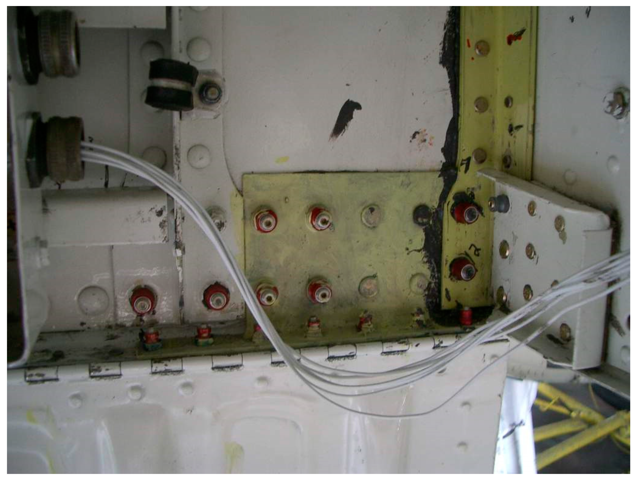
The replacement of fastener collars for NDI without the removal of the interference fit fastener pins may therefore help to maximize the fatigue life of the aircraft structure being inspected. An example of a structural area where repetitive collar replacement was considered for use in the RCAF is shown in
Figure 1 for Critical Point 16 on the CP140 Aurora [
6]. Selected hardware, test specimens, and applied loads for this project were based on the fasteners and structure at this location. Although the fatigue behavior of fasteners and joints in aircraft structure has been studied extensively [
5,
7], only a few studies have been done on the effect of repeated re-installation of fasteners. Li and Su [
8] studied the effect of repeatedly tightening and loosening the nut on titanium fasteners in a carbon fibre composite structure. They found that the clamping load decreased rapidly with repeated loosening-tightening cycles with a drop in clamp load between 66–76% within five repetitions and down to about 45% after 15 repetitions. Clamping load is critical to the fatigue performance of typical fastened aircraft structural joint, with a decrease in clamping load leading to early fatigue failure [
7].
Despite the current RCAF practice of replacing fastener pins and collars at each inspection, it is evident that there is a benefit, and it would be convenient, to retain the faster pins in some situations while removing only the collar to allow clear access to the fastener hole for inspection. The effect of repeated replacement of the collar on Hi-Lok pins on the subsequent strength and life of the fastener, and on the clamping load has not yet been reported. The aim of this research was to determine the effect of repetitive collar replacement on the residual clamping force, static strength, and fatigue life of retained Hi-Lok-type fastener pins. Fasteners were tested separately in both tension and shear to determine their behaviour under each primary loading condition. The results of this study will provide some evidence to support the practice of repeated collar replacements on retained Hi-Lok fasteners in aircraft structure where pin removal would be difficult, as is the case for Critical Point 16 on the CP140 Aurora [
6].
1.1. Equivalent Interference Fits
Most aerospace applications of Hi-Lok-type fasteners use interference fits between the pins and fastener holes to generate localized compressive stresses that reduce crack growth rates, improving the fatigue life of the component. Critical Point 16 on the CP140 Aurora is taken as a representative example of a fatigue-prone aircraft structure where Hi-Lok-type fasteners are employed. This location calls for 0.245” to 0.248” (6.22 mm to 6.30 mm) diameter fastener holes [
9,
10] in the 7075-T6 aluminum structure to accommodate 0.249” (6.32 mm) diameter steel fastener pins, resulting in an interference of 0.001” to 0.004” (0.025 mm to 0.100 mm) between the pins and the substrate.
In order to generate an equivalent amount of physical interference and resultant mechanical damage in the test specimens for this project, 0.245” (6.22 mm) diameter reamed fastener holes were used for all aluminum shear test fixtures. Because strength and fatigue requirements resulted in some of the test specimens, such as the tensile test jigs, being manufactured from high-strength steel, the physical interference of fastener holes in the steel test fixtures is reduced to ensure a similar level of mechanical damage to the fastener pin during installation. When determining the appropriate level of interference fit, it is assumed that the mechanical damage to the pin during installation is proportional to its radial strain.
For the aluminum plates in the shear test fixtures, total deformation at the fastener hole, ∆
Dtotal, is equal to the difference between the diameters of the fastener pin,
Dpin, and fastener hole,
Dhole:
Part of this deformation is caused by negative strain (radial compression) of the pin, while the remainder is accommodated by positive strain (radial expansion) of the fastener hole.
The deformation of the pin can be expressed in terms of the deformation of the fastener hole, knowing that the relative strains of these components will be directly proportional to the relative stiffness of the pin and plate materials:
where |
εpin| is the absolute radial strain of the pin (by convention, compressive strain will have a negative value),
εhole is the radial strain of the fastener hole,
Epin is the elastic modulus of the HL51-8-6 fastener pin material, 2.9 × 10
4 ksi (199 GPa) [
11],
Eplate is the elastic modulus of the 7075-T6 plate material, 1.03 × 10
4 ksi (70 GPa) [
11],
|∆Dpin| is the absolute radial deformation of the pin (compressive deformation will have a negative value), and
∆Dhole is the radial deformation of the fastener hole.
Substitute Equation (1) into Equation (2) and solve for the deformation of the pin:
where
.
Calculating deformation of the fastener pin in the aluminum plates:
Because aluminum has a much lower elastic modulus than steel, aluminum test jigs will have a greater amount of deformation relative to the steel fastener pin than steel test jigs, assuming equal dimensions. In order to ensure the same level of mechanical damage for the fastener pins in the steel axial test jig, radial strain (and therefore radial deformation) of the fastener pin is held constant.
To find the interference fit that will generate the same radial deformation of the pin in a high-strength steel fixture, Equation (2) is solved for deformation of the fastener hole:
Rearranging Equation (1), the initial diameter of the fastener hole is equal to:
Because the initial fastener hole diameter and radial deformation of the fastener hole are interdependent, the equations above are iterated for increasing values of Dhole until a solution converges. For a defined absolute pin deformation of 0.0011” (0.027 mm):
Dhole = 0.247” (6.30 mm).
A 0.247” diameter (6.30 mm) reamed fastener hole was therefore used for the high-strength steel test fixtures.
Author Contributions
D.F.H. performed the research in partial fulfillment of his MEng. degree in aerospace vehicle design with D.L.D. as the project supervisor and administrator. The individual contributions of the authors were as follows: Conceptualization, D.F.H. and D.L.D.; methodology, D.F.H.; validation, D.F.H.; formal analysis, D.F.H.; investigation, D.F.H.; resources, D.F.H. and D.L.D.; data curation, D.F.H.; writing—original draft preparation, D.F.H.; writing—review and editing, D.L.D.; supervision, D.L.D.; project administration, D.L.D.; funding acquisition, D.L.D.
Funding
Financial support of this research through the Department of National Defence, AERAC and the Natural Sciences and Engineering Research Council of Canada Discovery Grant # 239174 is gratefully acknowledged.
Conflicts of Interest
The authors declare no conflict of interest.
Nomenclature
| A = dimensionless constant |
| D = diameter (fastener or hole) |
| d2 = basic pitch diameter of the thread |
| di = inner bearing diameter of the nut |
| do = outer bearing diameter of the nut |
| E = elastic modulus |
| F = clamping force |
| Fsu = ultimate shear stress |
| Ftu = ultimate tensile stress |
| p = pitch of the threads |
| Ps = shear load |
| Psu = ultimate single shear strength |
| Ptu = ultimate tensile strength |
| Ton = tightening torque |
| Toff = loosening torque |
| β = half-included angle of the threads |
| ε = strain |
| μt = coefficient of friction for the thread |
| μe = coefficient of friction for the nut face |
References
- Lisi Aerospace. Hi-Lok Collar. Available online: http://www.lisi-aerospace.com/products/fasteners/internally-threaded/collars/Pages/nut-hi-lok.aspx (accessed on 5 March 2019).
- Hi-shear Corporation. Hi-Lok/Hi-Tigue Fastening Systems: Installation Instructions; Hi-Shear Corporation: Torrance, CA, USA, 1991. [Google Scholar]
- C-12-140-012/TR-001-Repair Instructions-CP140 Aurora/CP140A Arcturus-Structural Volume 1.
- Fahr, A.; Wallace, W. Aeronautical Applications of Non-Destructive Testing; DEStech Publications, Inc.: Lancaster, PA, USA, 2014. [Google Scholar]
- Jones, R.; Molent, L.; Pitt, S. Understanding Crack Growth in Fuselage Lap Joints. Theor. Appl. Fract. Mech. 2008, 49, 38–50. [Google Scholar] [CrossRef]
- Director General of Aerospace Engineering and Project Management. RMC 2005-007-SLA, -DGAEPM 482147 Request for Research, Scientific, and Technical Assistance from Royal Military College; DGAEPM: Ottawa, ON, Canada, 2006. [Google Scholar]
- Heshavanarayana, S.; Smith, B.L.; Gomez, C.; Caido, F. Fatigue-Based Severity Factors for Shear-Loaded Fastener Joints. J. Aircr. 2010, 47, 81–191. [Google Scholar]
- Li, C.; Su, H. The Influence of Pre-tension Load in the Composite Laminate Fastener Joint During Repeated Tightening. In Proceedings of the 21st International Conference on Composite Materials, Xi’an, China, 20–25 August 2017. [Google Scholar]
- IMP Aerospace. DWG # 939529-CA40; IMP Aerospace: Enfield, NS, Canada, 2010. [Google Scholar]
- Lockheed Martin Corporation. STP52-726; Lockheed Martin Corporation: Bethesda, MD, USA, 2010. [Google Scholar]
- LISI Aerospace. HL19 Hi-Lok Pin Data Sheet. Available online: http://www.lisi-aerospace.com/products/Pages/Fasteners-Catalog.aspx (accessed on 5 March 2019).
- Eccles, W. A New Approach to the Checking of the Tightness of Bolted Connections; Lubrication, Maintenance, and Tribotechnology; Paper Number: L144056; LUBMAT 2014: Manchester, UK, 2014. [Google Scholar]
- Eccles, W. A New Approach to the Tightness Checking of Bolts. Fastener + Fixing Magazine; Issue 90. 2014. Available online: http://boltscience.com/pages/a-new-approach-to-the-tightness-checking-of-bolts.pdf (accessed on 5 March 2019).
- LISI Aerospace. HL70 Hi-Lok Collar Data Sheet. Available online: http://www.lisi-aerospace.com/products/Pages/Fasteners-Catalog.aspx (accessed on 5 March 2019).
© 2019 by the authors. Licensee MDPI, Basel, Switzerland. This article is an open access article distributed under the terms and conditions of the Creative Commons Attribution (CC BY) license (http://creativecommons.org/licenses/by/4.0/).


