Mechanical Properties and Application of Right-Hand Rolling-Thread Steel Bolt in Deep and High-Stress Roadway

1
College of Mining and Safety Engineering, Shandong University of Science and Technology, 266590 Qingdao, China
2
Chongqing Research Institute, China Coal Research Institute, 400037 Chongqing, China
*
Author to whom correspondence should be addressed.
Metals 2019, 9(3), 346; https://doi.org/10.3390/met9030346
Submission received: 24 February 2019
/
Revised: 12 March 2019
/
Accepted: 17 March 2019
/
Published: 19 March 2019
Abstract
:The left-hand rolling-thread steel bolt has been proposed as a new bolt for controlling roadway surrounding rock. To explore the mechanism of a left-hand rolling-thread steel bolt in roadway surrounding rock control, its pretightening forces, tensile strengths, anchoring forces, and maximum working resistances were compared to normal right-hand full-thread steel bolts in the engineering context of the 1301 haulage roadway in the Daxing Coal Mine. Then, the left-hand threaded steel bolt was applied to the 1301 haulage roadway that the right-hand threaded steel bolt failed to control. The results indicated that due to the different effective tensile section area, the yield strength and tensile strength of the left-hand threaded steel bolt with the same material and diameter were more than 10% larger than those of the right-hand threaded steel bolt. Due to the different thread directions, the anchoring forces of the Φ18 and Φ20 left-hand threaded steel bolts were 46.2% and 33.3% greater than those of the right-hand threaded steel bolts, respectively. In the 1301 haulage roadway, the maximum pull-out force of the left-hand rolling-thread steel bolt with the same diameter was obviously greater than that of the right-hand full thread steel bolt. The displacements of the 1301 haulage roadway supported by the left-hand threaded steel bolt were not great. So, the left-hand threaded steel bolt can effectively control the surrounding rock in the 1301 haulage roadway.
1. Introduction
The purpose of controlling the surrounding rock in mine roadway is to ensure that excavations remain safe and open for their intended life span. There are many ways to control the rock that surrounds roadway, including active support and passive support. Passive support includes shed-type supports, wooden props, single hydraulic props, U-shaped steel supports [1,2,3], and concrete-filled steel tube supports [4,5]. Active support mainly includes bolt support, cable support, and grouting reinforcement [6,7]. Ordinary passive support can effectively control the shallow surrounding rock with less in situ stress [8]. The effect of passive support on controlling the deep surrounding rock with large in situ stress is not good [9,10]. Jansseune et al. [11] investigated the elastic failure of locally supported silos with U-shaped longitudinal stiffeners. Wang et al. [12] investigated the mechanical properties and deformation and failure mechanism of U-type confined concrete arch centering. A large number of engineering practices showed that rock bolting can effectively control the deep rock stratum with large in situ stress [13].
In 1872, a steel bar was first used to reinforce the rock stratum of mine roadway in North Wales, England. This was the embryonic form of bolt anchorage. By the 1940s, the application of rock bolting in underground engineering has been rapidly developed [14]. At present, rock bolting as an active support form is widely used in mine roadways, slopes, foundation pits, tunnels, and so on [15,16,17].
With the depletion of shallow coal resources, the depth of coal mining has gradually increased. The rock bolting can fully exert its advantages in deep roadway by improving the self-supporting capacity of the surrounding rock [18,19]. The pretightening force is the premise to ensure the effectiveness of active bolt support. By applying pretightening force to the bolt, the cohesion, internal friction angle, and equivalent deformation modulus of the surrounding rock in the anchorage range can be increased [20,21]. The wide application of prestressed bolts has resulted in a dramatic reduction in the number of fatalities due to roof fall accidents.
Many scholars have studied the mechanism of rock bolting to control the surrounding rock and optimized bolt support parameters. Micael et al. [22] investigated the strengthening of flat slabs with transverse reinforcement by the introduction of steel bolts using different anchorage approaches. Pedersen et al. [23] applied a finite element technique with super elements to solve the contact problem of the combined prestress and external load in an overall non-iterative way. Ana et al. [24] explored the use of dynamic testing of rock bolts in order to determine potentially broken bolts. Ding et al. [25] investigated the rock mass stability of large parallel tunnels in weak rocks by analyzing the corresponding monitoring data and field detection results. Li et al. [26] established a lateral vibration mechanics model for the structure and stress traits of bearing bolts, and analyzed the relation between lateral-vibration frequency and axial load.
At present, the most widely used bolt for controlling the rock surrounding a roadway is the right-hand full-thread steel bolt [27,28]. The right-hand full-thread bolts are made directly from threaded steel, and the machining process is simple. However, the thread pitch and thread rise angle of the full-thread bolts are large, resulting in a large friction force between the nut and the bolt rod when a pretightening force is applied. Therefore, it is difficult to apply a large pretightening force to a full-thread bolt. The on-site construction of roadway showed that the maximum pretightening force of full-thread bolts was 1–3 T, which obviously cannot meet the requirements for the active support of roadway surrounding rock. In addition, during the process of stirring resin by right-hand threaded bolts, the phenomenon of resin outflow often occurs, which significantly reduces the anchoring force of the bolts. This is due to the direction of the bolt threads [29,30,31]. Therefore, based on the shortcomings of the right-hand full-thread bolt, the left-hand rolling-thread bolt has been proposed as a new bolt for controlling roadway surrounding rock [32,33]. The left-hand rolling-thread bolts are machined from coal mine-specific left-hand threaded steel produced in a steel plant. The tail of the left-hand threaded steel is rolled through a thread rolling machine to reduce the pitch and rise angle of the thread, thereby improving the machining accuracy of the thread. So, the pretightening force, anchoring force, and tensile strength of the left-hand rolling-thread bolt are different from those of the right-hand full-thread bolt.
At present, the research and application of the left-hand rolling-thread steel bolts in mine roadway surrounding rock control are still in the initial stage. There is insufficient understanding about the superiority of the left-hand rolling-thread bolts over the right-hand full-thread bolts. There is a lack of research on the mechanism of the high pretightening force, high anchoring force, and high tensile strength of left-hand rolling-thread bolts. So, only by understanding the mechanism of the left-hand rolling-thread bolt can this technology be widely applied to mine roadways. Therefore, the research on the mechanism of the left-hand rolling-thread bolt is urgently needed.
The 1301 haulage roadway in Daxing Coal Mine was supported by normal right-hand full-thread steel bolts. However, the deformation of the rock surrounding the 1301 haulage roadway was large. This showed that the normal right-hand full-thread steel bolt cannot effectively control the stability of the surrounding rock in the 1301 haulage roadway. The 1301 haulage roadway is a deep and high-stress roadway. So, this paper is based on the 1301 haulage roadway for the engineering background.
To find an effective support structure for the 1301 haulage roadway, this paper systematically investigated the mechanism of the normal right-hand full-thread steel bolts and left-hand rolling-thread bolts in roadway surrounding rock control. The superiority of the left-hand rolling-thread steel bolts in comparison with the normal right-hand full-thread steel bolts in the roadway surrounding rock control was verified through engineering application. The left-hand threaded steel bolts can effectively control the stability of the surrounding rock in the 1301 haulage roadway.
2. Background
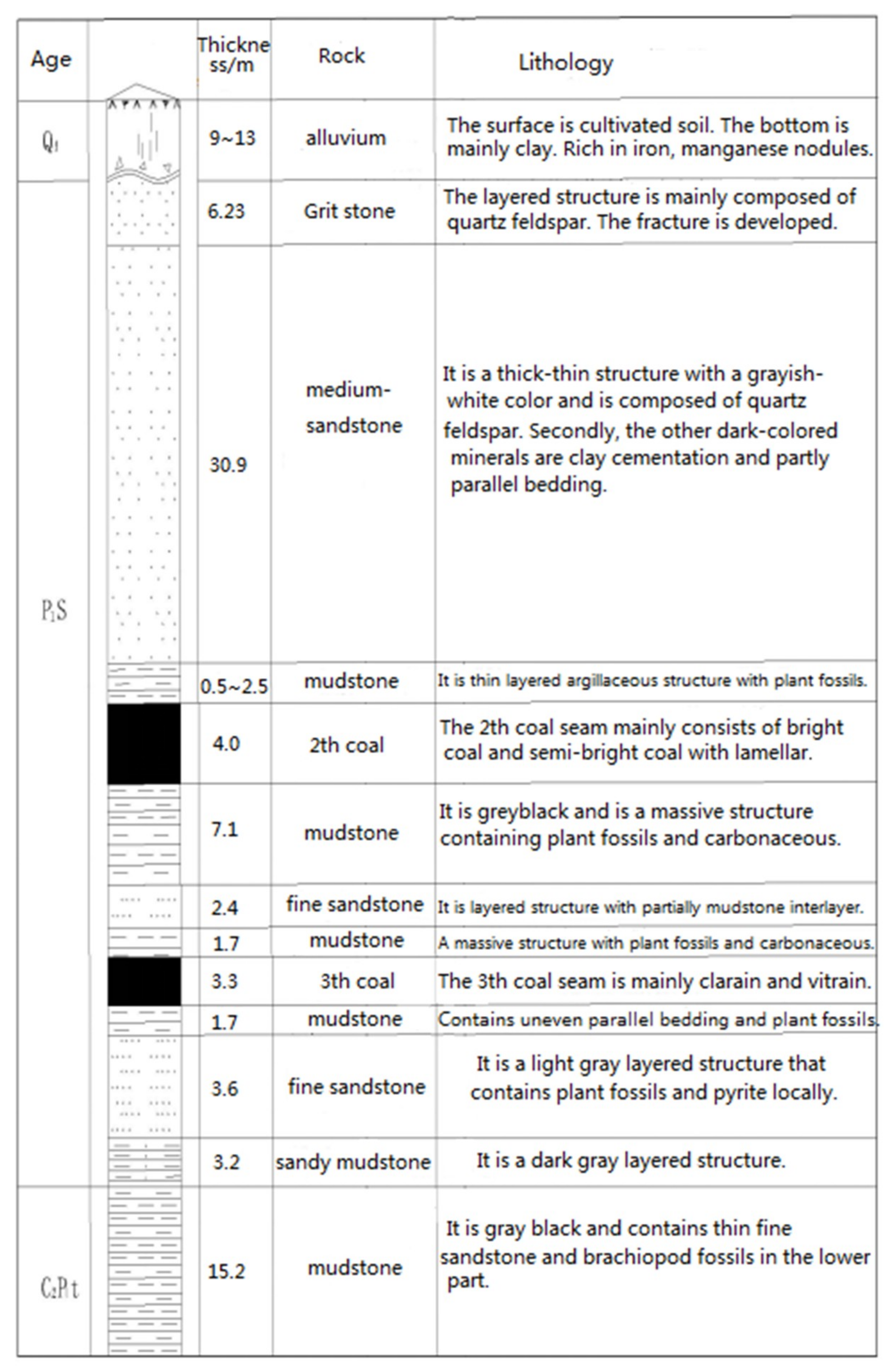
The Daxing Coal Mine is located in Zaozhuang county, Shandong Province, China. The ground level is +33.60 m. The major coal-bearing strata in the Daxing Coal Mine are composed of Taiyuan Formation, Lower Shihezi Formation, Shanxi formation, and Upper Shihezi Formation of Permo-Carboniferous. There are a total of 11 layers of coal in the Daxing Coal Mine. The thickness of the coal-bearing strata is about 1020 m. The thickness of coal seam is about 13.27–21.24 m. The total thickness of the workable seam is 7.3 m. The coal seam is a nearly horizontal coal seam of about 8°. The recoverable coal seams in the minefield are relatively stable. All of the recoverable coal seams are fat coking coals. Figure 1 shows the strata comprehensive histogram.
The second and third coal seam in the Daxing Coal Mine are the main mining objects. The buried depth of the main mining object is 532–876 m. The 1301 mining area currently is located on the second coal seam, with an average thickness of 4 m. The elevation of the 1301 haulage roadway in the 1301 mining area is −795.2 m. The position of the roadway is NW 309°. The in situ stress measurement at the 800-m level was carried out by the hydraulic fracturing technique. The results of in situ stress measurement are in Table 1. According to Table 1, the 1301 haulage roadway belongs to a deep high-stress roadway.
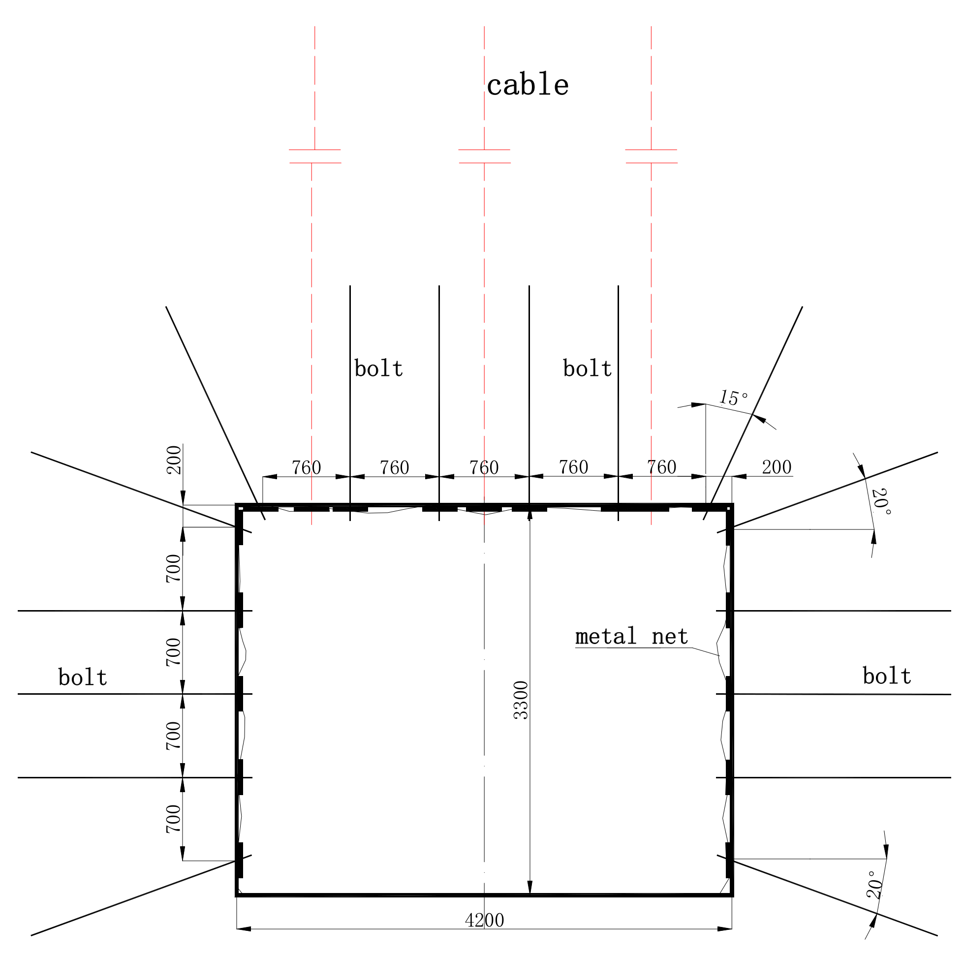
The height and width of the roadway are 3300 mm and 4200 mm, respectively. The rock surrounding the roadway is controlled by bolt-cable support. The bolts used in the 1301 haulage roadway were normal right-hand full-thread steel bolts. The support parameters were as follows: The sizes of the bolt and the cable were Φ20 mm × 2000 mm and Φ17.8 mm × 5300 mm, respectively. The diameter and length of the resin anchoring agent were 20 mm and 500 mm, respectively. The spacing-row distances of the bolts in the roof and the two sides of the roadway were 760 mm × 1000 mm and 700 mm × 1000 mm, respectively. The spacing-row distance of the cable was 1200 mm × 2000 mm. Figure 2 was the layout diagram of the roadway support parameters.
The deformation of the 1301 haulage roadway was large. The deformations of the local roof and sides were more than 1 m. The height of the 1301 haulage roadway was only 1.2–1.6 m (as shown in Figure 3). It showed that the load-bearing structure formed by the bolt-cable support and the surrounding rock cannot effectively resist the release of high ground stress. This supporting structure cannot meet the requirements of the 1301 haulage roadway surrounding rock control. It can be seen from the above supporting parameters that the above-mentioned support density has been relatively large. It is impossible to increase the support density in order to improve the surrounding rock control effect. So, improving the support performance of the single bolt is the only way. Therefore, it is urgent to find a new high-strength bolt instead of the normal right-hand full-thread steel bolt.
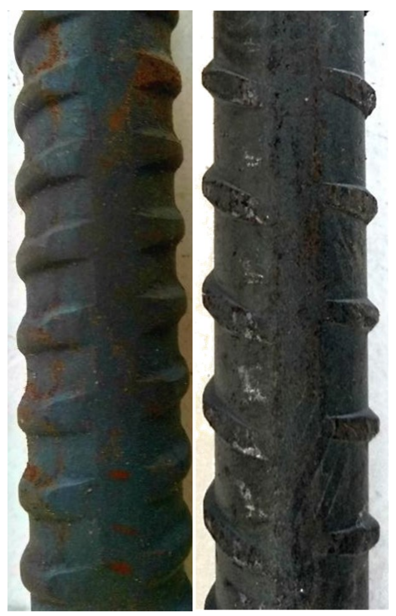
The left-hand rolling-thread bolts are machined from coal mine-specific left-hand threaded steel produced in a steel plant. The tail of the left-hand threaded steel is rolled through a thread rolling machine to reduce the pitch and rise angle of the thread, thereby improving the machining accuracy of the thread. As a result, the thread friction forces between the nut and bolt rod are reduced. In addition, the thread height of the left-hand threaded steel bolt with the same diameter is less than that of right-hand threaded steel bolt. The thread of the right-hand threaded steel is ring-shaped, and the thread of the left-hand threaded steel is only semi-ring shaped (as shown in Figure 4). So, the effective tensile section area of the left-hand threaded steel with the same diameter is larger than that of the right-hand threaded steel. The right-hand threaded steel bolt has an outward conveying force to the resin, and the left-hand threaded steel bolt has an inward conveying force to the resin. This results in the compactness between the resin and the left-hand threaded steel bolt being greater than that between the resin and the right-hand threaded steel bolt. Therefore, the pretightening force, tensile strength, and anchoring force of the left-hand rolling-thread steel bolt with the same material and diameter are larger than those of the right-hand full-thread steel bolt.
The difference between the left-hand rolling-thread steel bolt and right-hand full-thread steel bolt mainly includes two sides: the thread structure of the bolt tail (rolling thread and full thread) and the thread structure of the bolt rod (left-handed and right-handed). Therefore, in the following, the pretightening force of the rolling-thread and full-thread steel bolts, and the anchoring force and strength of the left-hand and right-hand threaded bolts were separately analyzed through experiments.
3. Experiments on Rolling-Thread and Full-Thread Steel Bolt
3.1. Pretightening Force Transformation Efficiency
The pretightening force on the bolt is achieved by applying a torque on the nut of the bolt. In order to investigate the relationship between the pretightening force on the bolt rod and the torque on the nut, the pretightening force transformation efficiency is proposed in this paper. The pretightening force transformation efficiency is the ratio between the pretightening force on the bolt and the torque on the nut. The pretightening force transformation efficiency is as follows:
where is the pretightening force transformation efficiency; is the pretightening force of the bolt; and is the torque applied to the nut of the bolt.
The most important factor affecting the pretightening force transformation efficiency of bolts is the thread friction forces. The thread structure and materials of the bolt rod and nut are the main factors determining the thread friction force. In addition, the friction forces between the nut and tray will also affect the pretightening force transformation efficiency. The friction forces between the nut and the tray can be reduced by installing a friction-reduction structure between the nut and the tray, such as a gasket. So, the frictional reduction structure can affect the pretightening force transformation efficiency of the bolts. Therefore, the pretightening force transformation efficiency is affected by the thread structure, the materials of the bolt rod and nut, and the frictional reduction structure:
where is the pretightening force transformation efficiency, is the thread structure, represents the materials of the bolt rod and nut; and is the frictional reduction structure.
- (1)
- The thread structure has the most important effect on the conversion of the torque on the nut to the pretightening force on the bolt rod. Applying the same torque to the nut of bolts with different thread sizes can result in different pretightening forces on the bolt rod. The rise angles of different sizes of threads are different, resulting in different thread friction forces [34,35,36,37]. The greater the thread friction force, the smaller the pretightening force transformation efficiency.
- (2)
- The materials of the bolt rod and nut are the second important factor affecting the pretightening force transformation efficiency. The material of the bolt rod is generally steel. The friction coefficients for the nuts and the bolt rod are different, depending on the materials with which they are made. The smaller the friction coefficient between the nut and the bolt rod, the more advantageous it is to convert the torque on the nut to the pretightening force on the bolt. In order to maximize the pretightening force transformation efficiency, the material with the minimum friction coefficient with steel should be selected to make the nut. The friction coefficients between the different materials for the nuts and the steel bolt rod are shown in Table 2. Table 2 shows that the friction coefficient between steel and ductile iron is the lowest, which is about 60% of the friction coefficient between steel and steel. Under the same thread structure and frictional reduction structure, the thread friction force of the bolt matching the ductile iron nut is 0.6 times that of the bolt matching the steel nut. Therefore, the pretightening force transformation efficiency of the bolt matching the ductile iron nut is the highest. At present, the nuts of the bolts used in mine roadways are mostly steel nuts [38,39,40,41], which is obviously disadvantageous for the high preload of bolts. Therefore, the bolt used in mine roadways should be matched with ductile iron nuts.
- (3)
- Frictional reduction structureThe tail structure of the bolt for mining service mainly includes a tray, spherical washer, frictional reduction gasket, and nut. The frictional reduction structure is mainly a frictional reduction gasket. The frictional reduction gasket can reduce the frictional torque between the nut and spherical washer, thereby improving the pretightening force transformation efficiency of the bolt. At present, the material of the frictional reduction gasket mainly includes four kinds, namely PTFE, nylon 1010, modified nylon 1010, and high-density polyethylene [42,43,44,45,46]. The nylon 1010 gasket has the best frictional reduction effect.
3.2. Test on Torque-Pretightening Force of Rolling-Thread and Full-Thread Steel Bolt
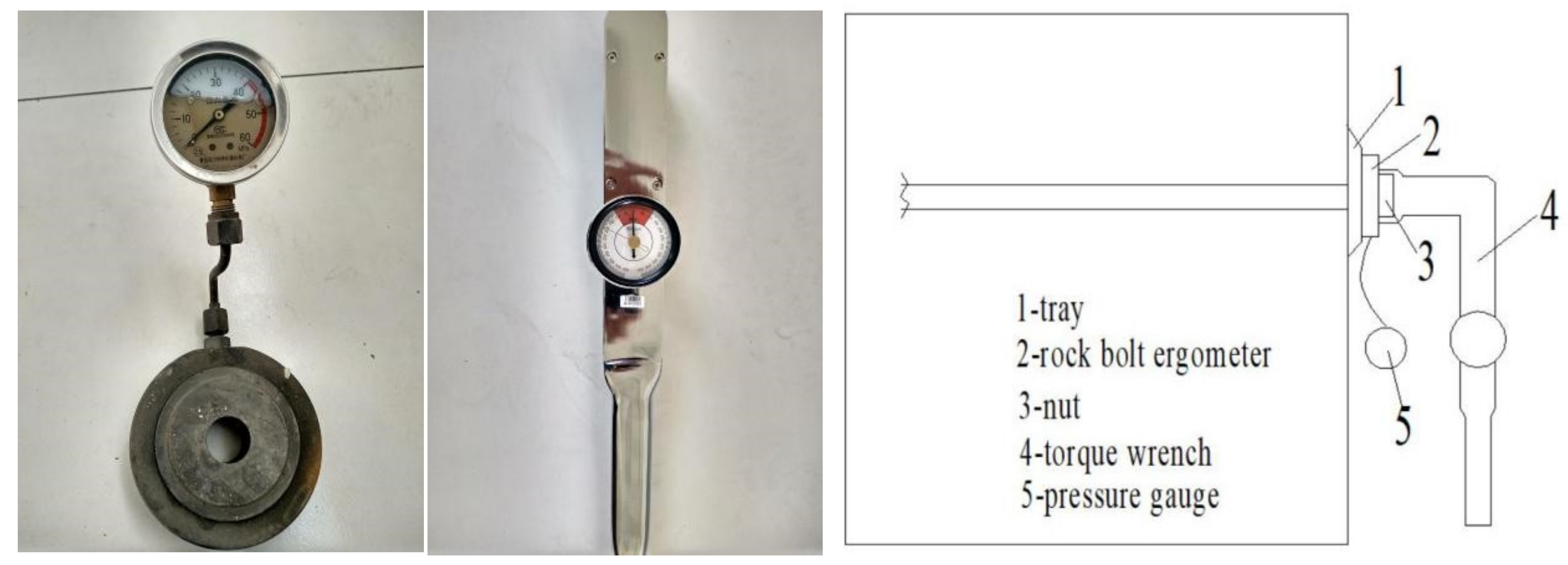
The most important factor affecting the pretightening force transformation efficiency of bolts is the thread friction forces. The friction coefficient between different materials for the nuts and the bolt rod is clear, but the influence mechanism of the thread structure on the thread friction force is not clear. To more intuitively investigate the torque-pretightening force transformation efficiency of the rolling-thread steel bolt and the full-thread steel bolt, the test on the torque-pretightening force of the bolt was conducted in the Daxing Coal Mine. The measuring instruments included torque wrenches and pressure gauges. The pressure gauges were installed between the nut and the tray. The test equipments were as follows: the sensitivity of the GYS-300KN rock bolt ergometer (Ark Mines Ltd., Taian, China) was 7.05 με/kN. The receiver was a KBJ static strain gauge (Donghua Testing Company, jingjiang, China). The range and accuracy of the NB-2096 torque wrench were 30–500 N·m and ±3%, respectively. The test on the torque-pretightening force of bolt was shown as in Figure 5.
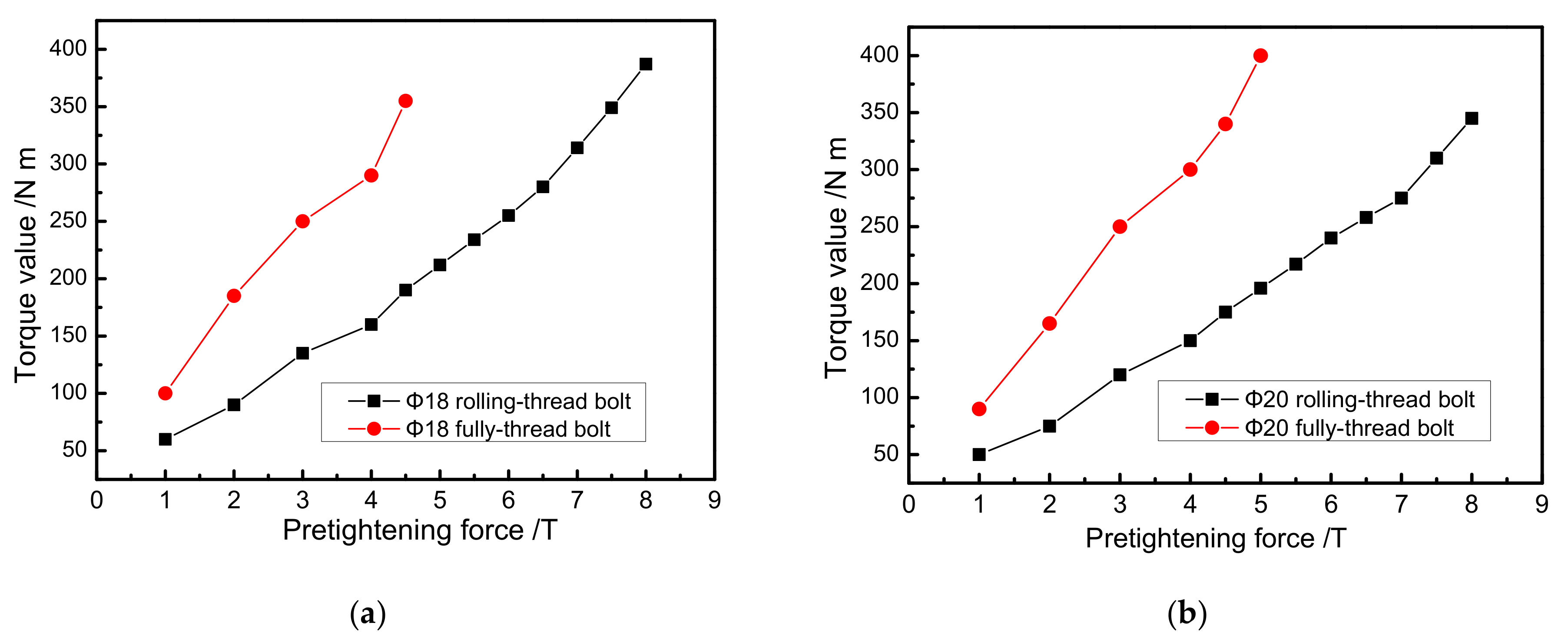
The rolling-thread steel bolt and full-thread steel bolt with diameters of Φ18mm and Φ20mm were selected for the torque-pretightening force test. The length of the bolts was 1800 mm. The bolt rods were made of Q500 steel. The nuts were made of ductile iron. The size of the tray was 150 mm × 150 mm × 10 mm. The frictional reduction gaskets made of Nylon 1010 were installed on the rolling- thread bolt and the full-thread bolt. The torque on the nut and the pretightening force on the bolt rod were respectively measured by the torque wrench and the rock bolt ergometer. The test result is shown in Figure 6.
The test results showed that under the same torque, the pretightening force of the rolling-thread steel bolt was much larger than that of the full-thread steel bolt. So, it is easier to apply a high pretightening force to the rolling-thread steel bolt than to the full-thread steel bolt.
Figure 6a shows that when the pretightening force of the Φ18 full-thread steel bolt reached 4 T, the pretightening force-torque curve started to rise rapidly. The maximum pretightening force of the Φ18 full-thread steel bolt was 4.5 T, corresponding to the torque of 355 N·m. At this time, the thread of the bolt tail was damaged significantly, and the torque on the nut cannot continue to increase. When the pretightening force of the Φ18 rolling-thread steel bolt reached 6.5 T, the pretightening force-torque curve started to rise rapidly. When the pretightening force of the Φ18 rolling-thread steel bolt reached 8 T, corresponding to the torque of 387 N·m, the bolt thread had not been destroyed. This showed that the pretightening force of the Φ18 rolling-thread steel bolt can continue to increase. When the pretightening force of bolts was 4.5 T, the pretightening force transformation efficiency of the Φ18 full-thread steel bolt was , and the pretightening force transformation efficiency of the Φ18 rolling-thread steel bolt was . . So, the pretightening force transformation efficiency of the Φ18 rolling-thread steel bolt was 1.866 times that of the Φ18 full-thread steel bolt.
Figure 6b shows that when the pretightening force of the Φ20 full-thread steel bolt reached 4 T, the pretightening force-torque curve started to rise rapidly. The maximum pretightening force of the Φ20 full-thread steel bolt was 5 T, corresponding to the torque of 400 N·m. At this time, the bolt thread was damaged significantly, and the torque on the nut cannot continue to increase. When the pretightening force of the Φ20 rolling-thread steel bolt reached 7 T, the pretightening force-torque curve started to rise rapidly. When the pretightening force of the Φ20 rolling-thread steel bolt reached 8 T, corresponding to the torque of 345 N·m, the bolt thread had not been destroyed. It showed that the pretightening force of the Φ20 rolling-thread steel bolt can continue to increase. When the pretightening force of bolts was 5 T, the pretightening force transformation efficiency of the Φ20 full-thread steel bolt was , and the pretightening force transformation efficiency of the Φ20 rolling-thread steel bolt was . . So, the pretightening force transformation efficiency of the Φ20 rolling-thread steel bolt was 2.04 times that of the Φ20 full-thread steel bolt.
Therefore, the pretightening force-torque transformation efficiency of the rolling-thread steel bolt is far greater than that of the full-thread steel bolt, by a factor of about 1.7 to 2.1. The reason is that the thread pitch and thread rise angle of the full-thread steel bolt are large, resulting in poor assembly precision between the nut and the bolt rod. The thread pitch and thread rise angle of the rolling-thread bolt are small, so the assembly precision between the nut and the bolt rod is high. The low pretightening force of the full-thread steel bolt reduces the active support effect of the bolt. However, the thread rolling steel bolt can exert a pretightening force of more than 8 T, which can guarantee the active support effect of the bolt.
4. Experiments on Left and Right-Hand Threaded Steel Bolts
4.1. Tensile Test of Left and Right-Hand Threaded Steel Bolt
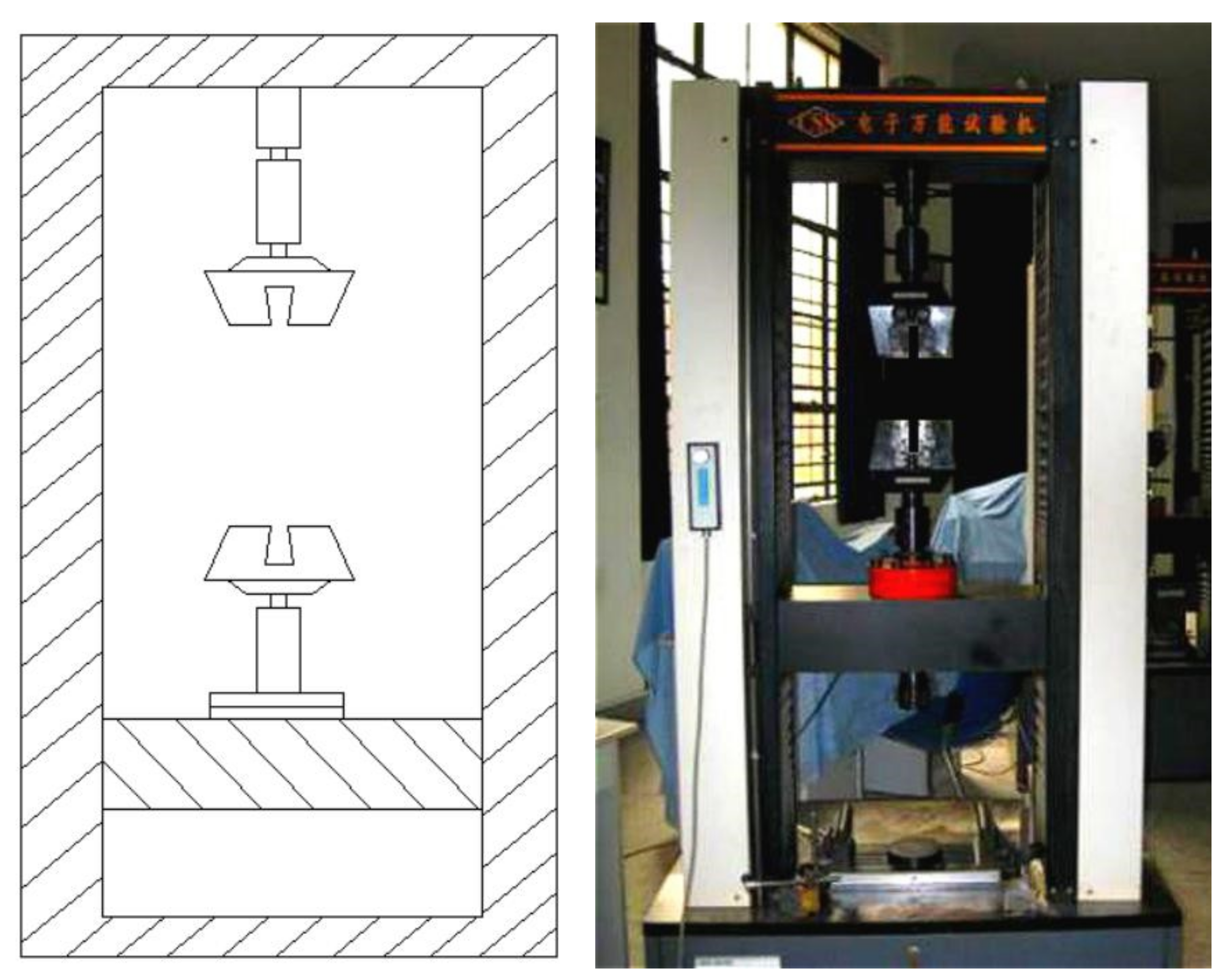
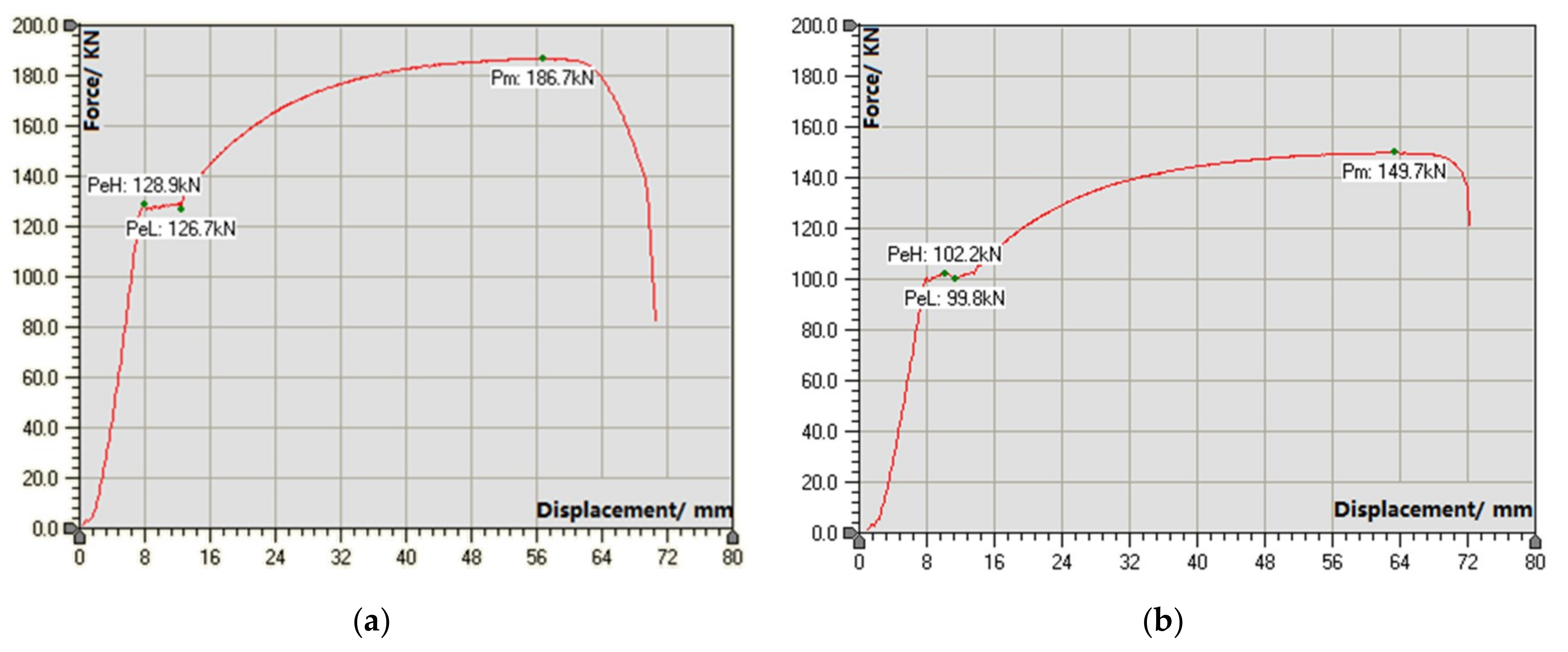
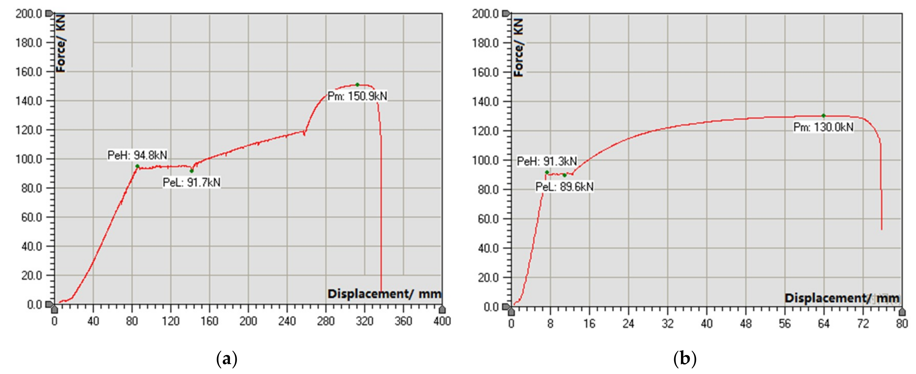
To investigate the tensile properties of left-hand and right-hand threaded steel bolts, the left-hand and right-hand threaded steel bolts with the material of Q335 steel and the diameters of Φ18 and Φ20 were selected for tensile tests in the laboratory. The tensile tests were carried out through employing a 300-kN CSS44100 electronic universal testing machine (Jinan liangong test technology company, Jinan, China, as indicated in Figure 7). A selected EDC100 digital controller produced by the German DOLI company (Tianjin, China) was used as the electric measuring and controlling system of a machine with the loading rate of 0.2 mm/min. The same experiments were carried out three times. Then, the representative curves were selected for analysis, as shown in Figure 6 and Figure 7. The tensile test curves of the left-hand and right-hand threaded steel bolts with the diameter of Φ20 are shown in Figure 8. The tensile test curves of the left-hand and right-hand threaded steel bolts with the diameter of Φ18 are shown in Figure 9. The reason for the large displacement of the bolt in Figure 9a was that the end of the bolt slid in the test, but the bolt finally broke. So, the bolt slip had no effect on the yield strength and tensile strength of the bolt. The test was effective.
Figure 6 and Figure 7 showed that the left-hand and right-hand threaded steel bolts first passed through the elastic deformation stage to reach the yield strength. Then, it entered the plastic deformation stage, reaching its maximum tensile strength and shrinking damage. Figure 8 showed that the yield strength and tensile strength of the Φ20 left-hand threaded steel bolt were 126.7 KN and 186.7 KN, respectively. The yield strength and tensile strength of the Φ20 right-hand threaded steel bolt were 99.8 KN and 149.7 KN, respectively. Figure 9 showed that the yield strength and tensile strength of the Φ18 left-hand threaded steel bolt were 94.8 KN and 150.9 KN, respectively. The yield strength and tensile strength of the Φ18 right-hand threaded steel bolt were 89.6 KN and 130.0 KN, respectively. By comparison, the yield strength and tensile strength of the Φ20 left-hand threaded steel bolt were respectively 26.95% and 24.72% higher than those of the Φ20 right-hand threaded steel bolt. The yield strength and tensile strength of the Φ18 left-handed thread steel bolt were respectively 5.8% and 16.08% higher than those of the Φ18 right-hand threaded steel bolt. Due to the sliding of the Φ18 left-hand threaded steel bolt rod in the tensile test, the measured yield strength of the bolt was lower than the actual yield strength.
The effective tensile section areas of the left-hand and right-hand threaded steel bolts are shown in Figure 10. Due to the different thread shape and thread height, the effective tensile section area of the left-hand threaded steel bolt with the same diameter was more than 10% larger than that of the right-hand threaded steel bolt. The yield stress and breaking stress of the same type steel are uniform. So, the greater the effective tensile section area of the bolt with the same material, the greater the strength. Normally, the yield strength and tensile strength of the left-hand threaded steel bolt with the same material and diameter were more than 10% higher than those of the right-hand threaded steel bolt.
4.2. Anchorage Test of Left-Hand and Right-Hand Threaded Steel Bolts
The screw thread directions of the left-hand and right-hand threaded steel bolts are different, resulting in different directions of the conveying force of the bolt to the resin during the process of stirring the resin by bolt. So, the resin stresses of the left-hand and right-hand threaded steel bolts are different, resulting in different anchoring forces of the left-hand and the right-hand threaded steel bolt with the same material and diameter. To investigate the anchorage performance of left-hand and right-hand threaded steel bolts, the pull-out tests were conducted by employing a 300-KN CSS44100 electronic universal testing machine (as indicated in Figure 7).
The left-hand and right-hand threaded steel bolts with the material of Q335 steel, the length of 1800 mm, and the diameters of Φ18 and Φ20 were selected for anchorage tests. The bolt hole in mine roadways was simulated by the steel tube with the diameter of 28 mm and the length of 400 mm. The resin type was K2530. The stirring time of the resin was 40 s. The tests were started 30 min after stirring. The gripping length of the testing machine was 180 mm. The loading rate of the testing machine was 0.086 mm/s. The same experiments were carried out three times. Then, the representative curves were selected for analysis, as shown in Figure 11 and Figure 12. Figure 11 shows the anchorage test diagram of the left-hand and right-hand threaded steel bolts. The displacement-load curves of the pull-out tests are shown in Figure 12.
Figure 12 showed that the anchoring forces of the Φ18 left-hand and right-hand threaded steel bolts were 136 KN and 93 KN, respectively. The anchoring force of the Φ 18 left-hand threaded steel bolt was 46.2% greater than that of the right-hand threaded steel bolt. The anchoring forces of the Φ20 left-hand and right-hand threaded steel bolts were 144 KN and 108 KN, respectively. The anchoring force of the Φ20 left-hand threaded steel bolt was 33.3% greater than that of the right-hand threaded steel bolt. Therefore, the screw thread directions had a significant effect on the anchoring force of the bolts. The anchoring force of the bolt has a positive correlation with the compactness between the resin and the anchoring section. During the process of stirring the resin by bolt, the screw thread direction of the right-hand threaded steel bolt was the same as the stirring direction of the bolt. So, an outward conveying force of the bolt to the resin was generated, causing the resin to overflow outward. The compactness between the resin and the anchoring section of the right-hand threaded steel bolt gradually decreased, which seriously reduced the anchoring force of the resin. However, the screw thread direction of the left-hand threaded steel bolt was different from the stirring direction of bolt in the process of stirring the resin by bolt. An inward conveying force of the bolt to the resin was generated, causing the compactness between the resin and the anchoring section of the bolt to gradually increase. So, the anchoring force was increased. Therefore, the anchoring forces of the left-hand threaded steel bolts with the same material and diameter were significantly greater than those of the right-hand threaded steel bolts.
5. Pull-Out Test in the Field
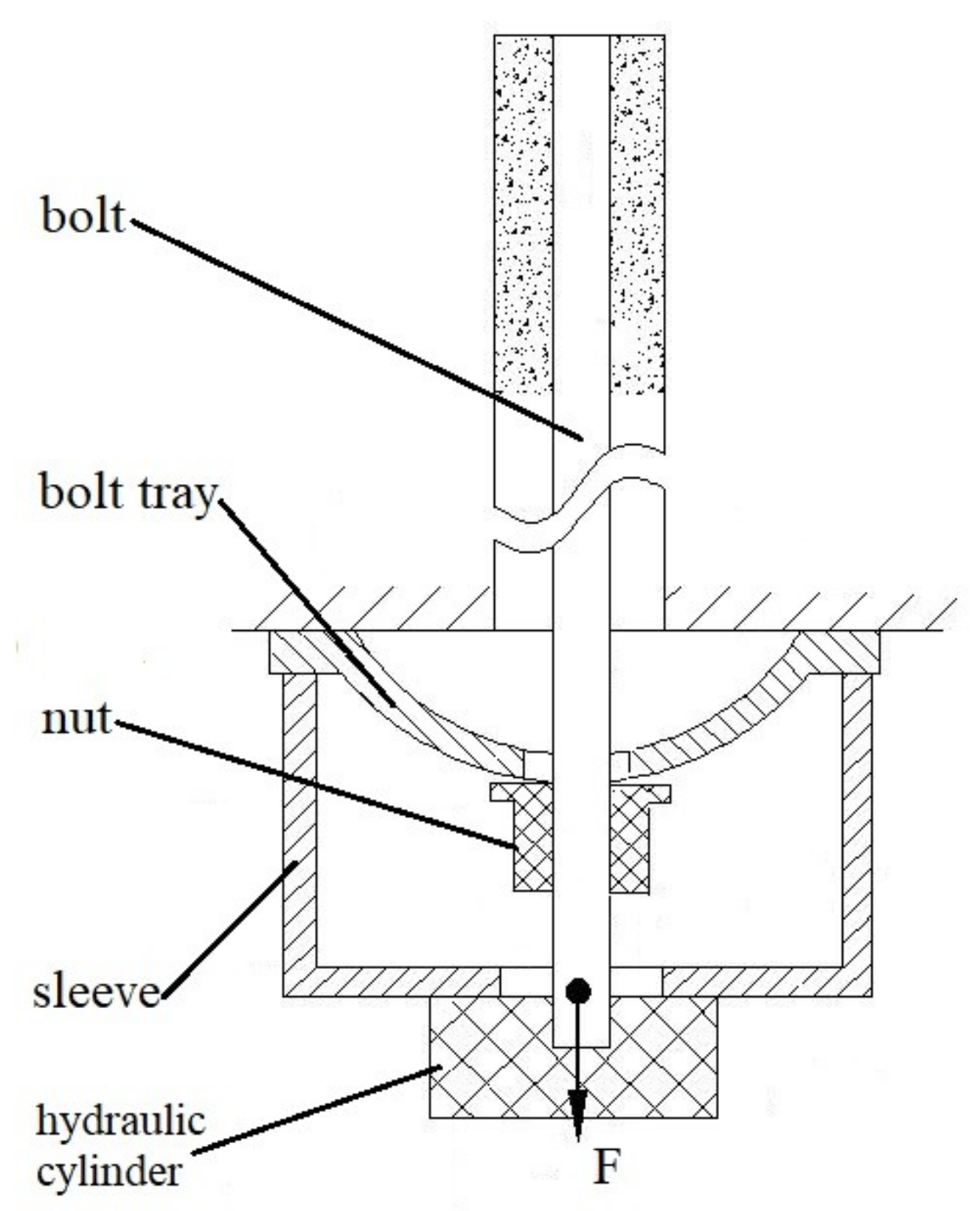
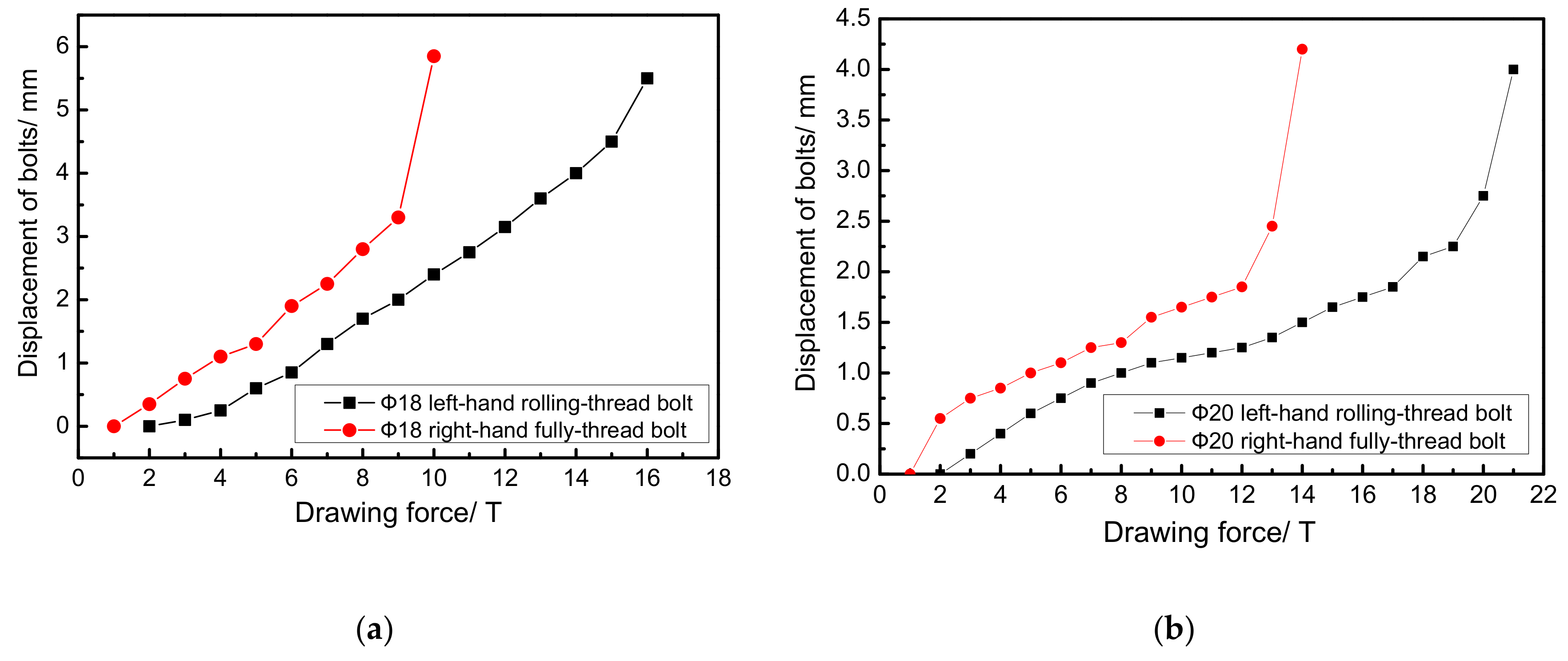
To compare and analyze the supporting performance of the the normal right-hand full-thread steel bolt and left-hand rolling-thread steel bolt, four groups of bolt pull-out tests were carried out in the 1301 haulage roadway. The left-hand rolling-thread bolt and right-hand full-thread bolt with the material of Q335 and the diameters of Φ18 × 1800 mm and Φ20 × 1800 mm were selected. The size of the tray was 150 mm × 150 mm × 8 mm. The diameter of the drill was 28 mm. The tests were started 40–50 min after installing the bolt. The pull-out tests in the 1301 haulage roadway were performed by an HC-10/20/30 pull-out apparatus (as shown in Figure 13). The pull-out apparatus consisted of an adapter, sleeve, tension rod, hydraulic chuck, flat washer, fitting nut, dial gauge, support bar, and so on. The schematic diagram of the bolt pull-out test is shown in Figure 14. The relationship between the pull-out force and the displacement of bolts in the pull-out test is shown in Figure 15.
As shown in Figure 14, the pull-out force applied to the bolt was F. In the initial stage, when the pull-out force was less than the axial force of the bolt, there was a pressure between the nut and the tray. When the pull-out force was equal to the axial force of the bolt, the pressure between the nut and the tray was zero. As the pull-out force continued to increase, the dial gauge reading began to change. Therefore, the pull-out force when the dial gauge reading began to change was the initial axial force of the bolt.
Figure 15a showed that the pretightening force of the Φ18 left-hand rolling-thread bolt was between 3–4 T. When the drawing force was between 4–15 T, the bolt was in the elastic stage. When the drawing force was greater than 15 T, the displacement of the bolt increased rapidly, indicating that the drawing force reached the yield stress of the bolt rod or anchoring agent, and plastic deformation began to occur. The pretightening force of the Φ18 right-hand full-thread bolt was between 1–2 T. When the drawing force was between 2–9 T, the bolt was in the elastic stage. When the drawing force was greater than 9 T, the drawing force reached the yield stress of the bolt rod or anchoring agent, and plastic deformation began to occur. Therefore, the maximum working resistance of the Φ18 left-hand rolling-thread bolt was obviously greater than that of the Φ18 right-hand full-thread bolt.
Figure 15b shows that the pretightening force of the Φ20 left-hand rolling-thread bolt was between 3–4 T. When the drawing force was between 5–20 T, the bolt was in the elastic stage. When the drawing force was greater than 20 T, the displacement of the bolt increased rapidly, indicating that the drawing force reached the yield stress of the bolt rod or anchoring agent, and the plastic deformation began to occur. The pretightening force of the Φ20 right-hand full-thread bolt was between 1–2 T. When the drawing force was 2–13 T, the bolt was in the elastic stage. When the drawing force was greater than 13 T, the drawing force reached the yield stress of the bolt rod or anchoring agent, and plastic deformation began to occur. Therefore, the maximum working resistance of the Φ20 left-hand rolling-thread bolt was obviously greater than that of the Φ20 right-hand full-thread bolt.
Generally, the maximum working resistance of the left-hand rolling-thread steel bolt with the same material and diameter was obviously greater than that of the right-hand full-thread steel bolt. This was because the left-hand rolling-thread bolt has a greater anchoring force and tensile strength than the right-hand full-thread bolt.
6. Application
According to the above test and analysis, it can be clearly seen that the left-hand rolling-thread steel bolt has greater advantages than the right-hand full-thread steel bolt regarding surrounding rock control. The pretightening force transformation efficiency is the ratio between the pretightening force on the bolt and the torque on the nut. The pretightening force-torque transformation efficiency of the rolling-thread steel bolt is far greater than that of the full-thread steel bolt. It is easier to apply a high pretightening force to the rolling-thread steel bolt than to the full-thread steel bolt. Due to the different thread shape and thread height, the yield strength and tensile strength of the left-hand threaded steel bolt with the same material and diameter are more than 10% higher than those of the right-hand threaded steel bolt. Due to the different screw thread directions, the anchoring forces of the left-hand threaded steel bolts with the same material and diameter are significantly greater than those of the right-hand threaded steel bolts.
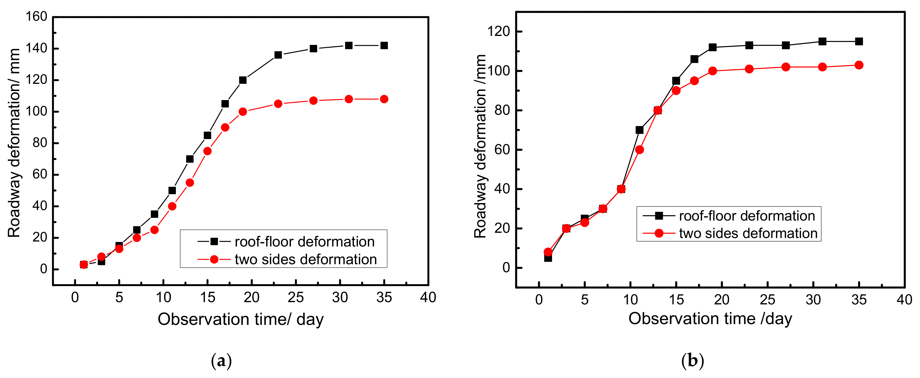
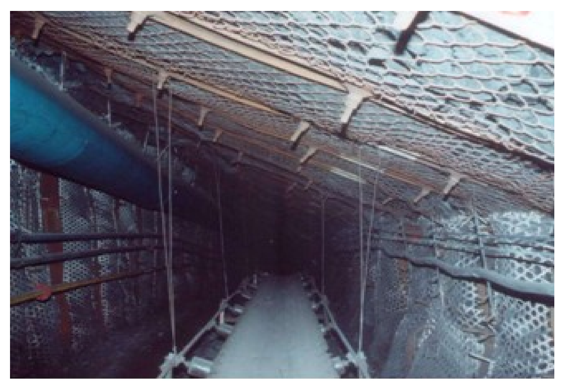
In order to analyze the effects of the left-hand rolling-thread steel bolt in field applications, the test roadways with two sections of 50 m were selected in the 1301 haulage roadway, which was named as the test roadway. The roadway support parameters are both shown in Figure 2. The surrounding rock of the test roadway was controlled by Φ20 left-hand rolling-thread steel bolts. The observation stations 1# and 2# were set up in the test roadway. The distances of the roof floor and the two sides of the test roadways were measured by the laser range finder once every two days within 20 days, and then once every four days after 20 days. Figure 16 shows the deformations of the test roadway surrounding rock. Figure 17 shows the test roadway after the stability of the surrounding rock.
Figure 16a showed that the maximum deformations of the roof floor and the two sides of observation station 1# were 142 mm and 108 mm, respectively. Figure 16b showed that the maximum deformations of the roof floor and the two sides of observation station 2# were 115 mm and 103 mm, respectively. The surrounding rocks of observation station 1# and observation station 2# were basically stable on the 23rd and 19th days, respectively. So, the deformations of the roof floor and the two sides of the roadway were not large. Figure 17 showed that the surrounding rock structure of the test roadway was complete. Compared with Figure 3, the surrounding rock control effect of the test roadway supported by the left-hand threaded steel bolt was obviously better than that of the roadway supported by the normal right-hand full-thread steel bolt. The reason was that the anchoring force and tensile strength of the left-hand rolling-thread steel bolt were greater than those of the right-hand full-thread steel bolt. Therefore, the left-hand rolling-thread steel bolts can can effectively control the stability of the surrounding rock in the 1301 haulage roadway of Daxing Coal Mine.
7. Conclusions
- (1)
- The pretightening force transformation efficiency is the ratio between the pretightening force on the bolt and the torque on the nut. The factors affecting the pretightening force transformation efficiency of the bolts include the thread structure, the bolt rod and nut materials, and the frictional reduction structure. It is easier to apply a high pretightening force to the rolling-thread steel bolt than to the full-thread steel bolt.
- (2)
- Due to the different thread shape and thread height, the effective tensile section area of the left-hand threaded steel bolt with the same diameter is more than 10% larger than that of the right-hand threaded steel bolt. So, the yield strength and tensile strength of the left-hand threaded steel bolt with the same material and diameter are more than 10% higher than those of the right-hand threaded steel bolt.
- (3)
- The anchoring forces of the Φ18 and Φ20 left-hand threaded steel bolt were 46.2% and 33.3% greater than those of the right-hand threaded steel bolt, respectively. Due to the different screw thread directions, the anchoring forces of the left-hand threaded steel bolts with the same material and diameter are significantly greater than those of the right-hand threaded steel bolts.
- (4)
- In the 1301 haulage roadway, the maximum pull-out force of the left-hand threaded steel bolt with the same diameter was obviously greater than that of the right-hand threaded steel bolt.
- (5)
- The surrounding rock control effect of the test roadway supported by left-hand threaded steel bolts was obviously better than that of the roadway supported by the normal right-hand threaded steel bolts. The left-hand threaded steel bolts can can effectively control the stability of the surrounding rock in the 1301 haulage roadway of the Daxing Coal Mine.
The left-hand rolling-thread bolts are machined from coal mine-specific left-handed threaded steel produced in a steel plant. So, the processing materials of the left-hand rolling-thread bolts are not extensive. At present, many mines have not used left-hand rolling-thread bolts, and they do not recognize their advantages. Therefore, it is necessary to make those designing the mines understand the left-hand rolling-thread bolt by theoretical analysis and experimental research, and then apply it widely.
Author Contributions
J.Z. contributed the literature search, study design, and data analysis. J.S. contributed the data interpretation and data collection. L.L. contributed the writing and data analysis. Q.L. contributed the modification of pictures and contents.
Funding
This research was financed by Shandong Province Key R&D Plan (Grant No. 2018GSF116006).
Acknowledgments
The authors would like to thank Daxing Coal Mine for the field trial monitoring.
Conflicts of Interest
The authors declare no conflict of interest.
References
- Tan, X.; Chen, W.Z.; Liu, H.Y.; Andrew, H.C.; Tian, H.M.; Meng, X.J.; Wang, F.Q.; Deng, X.L. A combined supporting system based on foamed concrete and U-shaped steel for underground coal mine roadways undergoing large deformations. Tunn. Undergr. Space Technol. 2017, 68, 196–210. [Google Scholar] [CrossRef]
- Zhao, Y.M.; Liu, N.; Zheng, X.G.; Zhang, N. Mechanical model for controlling floor heave in deep roadways with U-shaped steel closed support. Int. J. Min. Sci. Technol. 2015, 25, 713–720. [Google Scholar] [CrossRef]
- Jiao, Y.Y.; Song, L.; Wang, X.Z.; Coffi, A.A. Improvement of the U-shaped steel sets for supporting the roadways in loose thick coal seam. Int. J. Rock Mech. Min. Sci. 2013, 60, 19–25. [Google Scholar] [CrossRef]
- Zhang, J.P.; Liu, L.M.; Cao, J.Z.; Yan, X.; Zhang, F.T. Mechanism and application of concrete-filled steel tubular support in deep and high stress roadway. Constr. Build. Mater. 2018, 163, 233–246. [Google Scholar] [CrossRef]
- Huang, W.P.; Yuan, Q.; Tan, Y.L.; Wang, J.; Liu, G.L.; Qu, G.L.; Li, C. An innovative support technology employing a concrete- filled steel tubular structure for a 1000-m-deep roadway in a high in situ stress field. Tunn. Undergr. Space Technol. 2018, 73, 26–36. [Google Scholar] [CrossRef]
- Zhang, J.P.; Liu, L.M.; Li, Q.H.; Peng, W.; Zhang, F.T.; Cao, J.Z.; Wang, H. Development of cement- based self-stress composite grouting material for reinforcing rock mass and engineering application. Constr. Build. Mater. 2019, 201, 314–327. [Google Scholar] [CrossRef]
- Zhang, J.P.; Liu, L.M.; Zhang, F.T.; Cao, J.Z. Development and application of new composite grouting material for sealing groundwater inflow and reinforcing wall rock in deep mine. Sci. Rep. 2018, 8, 1–11. [Google Scholar]
- Hatzor, Y.H.; Wainshtein, I.; Mazor, D.B. Stability of shallow karstic caverns in blocky rock masses. Int. J. Rock Mech. Min. Sci. 2010, 47, 1289–1303. [Google Scholar] [CrossRef]
- Hsu, S.C.; Chiang, S.S.; Lai, J.R. Failure mechanisms of tunnels in weak rock with interbedded structures. Int. J. Rock Mech. Min. Sci. 2004, 41, 670–675. [Google Scholar] [CrossRef]
- Wang, Q.; Jiang, B.; Pan, R.; Li, S.C.; He, M.C.; Sun, H.B.; Qin, Q.; Yu, H.C.; Luan, Y.C. Failure mechanism of surrounding rock with high stress and confined concrete support system. Int. J. Rock Mech. Min. Sci. 2018, 102, 89–100. [Google Scholar] [CrossRef]
- Jansseune, A.; Wouter, D.C.; Jan, B. Elastic failure of locally supported silos with U-shaped longitudinal stiffeners. KSCE J. Civ. Eng. 2015, 19, 1041–1049. [Google Scholar] [CrossRef]
- Wang, Q.; Jiang, B.; Li, S.C.; Wang, D.C.; Wang, F.Q.; Li, W.T.; Ren, Y.X.; Guo, N.B.; Shao, X. Experimental studies on the mechanical properties and deformation & failure mechanism of U-type confined concrete arch centering. Tunn. Undergr. Space Technol. 2016, 51, 20–29. [Google Scholar]
- Suorineni, F.T.; Kaiser, P.K.; Henning, J.G. Safe rapid drifting-support selection. Tunn. Undergr. Space Technol. 2008, 23, 682–699. [Google Scholar] [CrossRef]
- Shchetinin, V.V. Investigation of different types of flexible anchor tendons (rock bolts) for stabilization of rock masses. Hydrotech. Constr. 1974, 8, 315–320. [Google Scholar] [CrossRef]
- Manh, H.T.; Sulem, J.; Subrin, D.; Billaux, D. Anisotropic timedependent modeling of tunnel excavation in squeezing ground. Rock Mech. Rock Eng. 2015, 48, 2301–2317. [Google Scholar] [CrossRef]
- Panarace, M.; Garnil, C.; Cane, L.; Rodr, G.E.; Medina, M. Identification, remediation, and analysis of karst sinkholes in the longest railroad tunnel in South Korea. Eng. Geol. 2012, 135, 92–105. [Google Scholar]
- Zhang, G.H.; Jiao, Y.Y.; Wang, H. Outstanding issues in excavation of deep and long rock tunnels: A case study. Can. Geotech. J. 2014, 51, 984–994. [Google Scholar] [CrossRef]
- Villaescusa, E.; Varden, R.; Hassell, R. Quantifying the performance of resin anchored rock bolts in the Australian underground hard rock mining industry. Int. J. Rock Mech. Sand Min. Sci. 2008, 30, 94–102. [Google Scholar] [CrossRef]
- Campbell, R.; Mould, R.J. Impacts of gloving and un-mixed resin in fully encapsulated roof bolts on geotechnical design assumption sand strata control. Int. J. Coal Geol. 2005, 64, 116–125. [Google Scholar] [CrossRef]
- Ivanovi, A.; Neilson, R.D. Modelling of debonding along the fixed anchor length. Int. J. Rock Mech. Min. Sci. 2009, 46, 699–707. [Google Scholar] [CrossRef]
- Ivanovic, A.; Neilson, R.D. Influence of geometry and material properties on the axial vibration of a rock bolt. Int. J. Rock Mech. Min. Sci. 2008, 45, 941–951. [Google Scholar] [CrossRef]
- Inácio, M.M.G.; Ramos, A.P.; Faria, D.M.V. Strengthening of flat slabs with transverse reinforcement by introduction of steel bolts using different anchorage approaches. Eng. Struct. 2012, 44, 63–77. [Google Scholar]
- Pedersen, N.L.; Pedersen, P. Bolt-plate contact assemblies with prestress and external loads: Solved with super element technique. Comput. Struct. 2009, 87, 1374–1383. [Google Scholar] [CrossRef]
- Ana, I.; Richard, D.N. Non-destructive testing of rock bolts for estimating total bolt length. Int. J. Rock Mech. Min. Sci. 2013, 64, 36–43. [Google Scholar]
- Ding, X.L.; Weng, Y.H.; Zhang, Y.T.; Xu, T.J.; Wang, T.L.; Rao, Z.W.; Qi, Z.F. Stability of Large Parallel Tunnels Excavated in Weak Rocks: A Case Study. Rock Mech. Rock Eng. 2017, 50, 2443–2464. [Google Scholar] [CrossRef]
- Li, Q.F.; Zhu, C.Q.; Duan, Y. Theoretical and experimental research on characteristics of lateral vibration for a pre-stress bolt supporting system. J. Coal Sci. Eng. 2009, 15, 33–37. [Google Scholar] [CrossRef]
- Isabelle, T.; Laura, B.M.; Faouzi, H.H.; Jacques, S.; Zbigniew, L.; Aleksander, W. Laboratory pull-out tests on fully grouted rock bolts and cable bolts: Results and lessons learned. J. Rock Mech. Geotech. Eng. 2017, 9, 843–855. [Google Scholar]
- Li, C.C. Performance of D-bolts Under Static Loading. Rock Mech. Rock Eng. 2012, 45, 183–192. [Google Scholar]
- Korane, K.; Sauer, S. The nuts and bolts of specifying fastener torque. Mach. Des. 1998, 70, 81–83. [Google Scholar]
- Ibrahim, R.A.; Pettit, C. Uncertainties and dynamic problems of bolted joints and other fasteners. J. Sound Vib. 2005, 279, 857–936. [Google Scholar] [CrossRef]
- Anders, J.; Cismoski, D.; Pattillo, P.; Fox, A.; Pitts, D. Analysis of Thread Engagement Requirements for Studs and Nuts. In Proceedings of the SPE Annual Technical Conference and Exhibition, Denver, CO, USA, 21–24 September 2008. [Google Scholar]
- Shigeru, Y.; Amiya, K.; Yasunori, S. Effects of residual stress on elastic plastic behavior of metallic glass bolts formed by cold thread rolling. J. Mater. Process. Technol. 2014, 214, 2593–2599. [Google Scholar]
- Zhang, M.G. Roadway Support Technology in Goaf of Ultra-close Distance Coal Seams. J. Shandong Univ. Sci. Technol. 2018, 37, 35–41. [Google Scholar]
- Ahmad, R.Z.; Oyadiji, S.O. Clamping of fine Kirschner wires in external fixators. Proc. Inst. Mech. Eng. Part H 2016, 230, 1036–1042. [Google Scholar]
- Lambert, T.H. Effects of variations in the screw thread coefficient of friction on the clamping force of bolted connections. ARCHIVE J. Mech. Eng. Sci. 1962, 4, 401–406. [Google Scholar] [CrossRef]
- Abhijit, B.; Barnik, S.R.; John, D.B.; Subhash, C.S. An experimental investigation of torque and force generation for varying tool tilt angles and their effects on microstructure and mechanical properties: Friction stir welding of AA 6061-T6. J. Manuf. Process. 2018, 31, 395–404. [Google Scholar]
- Philipp, K.; Peter, G. Defect detection in thread rolling processes—Experimental study and numerical investigation of driving parameters. Int. J. Mach. Tools Manuf. 2018, 129, 27–36. [Google Scholar]
- Kang, H.; Wu, Y.; Gao, F.; Jiang, P.; Cheng, P.; Meng, X.; Li, Z. Mechanical performances and stress states of rock bolts under varying loading conditions. Tunn. Undergr. Space Technol. 2016, 52, 138–146. [Google Scholar] [CrossRef]
- Tao, Z.G.; Zhao, F.; Wang, H.J.; Zhang, H.J.; Peng, Y.Y. Innovative constant resistance large deformation bolt for rock support in high stressed rock mass. Arabian J. Geosci. 2017, 10, 341. [Google Scholar]
- Lip, H.T.; Mehmet, E.U. Ultimate Tilt-Bearing Capacity of Bolted Connections in Cold-Reduced Steel Sheets. J. Struct. Eng. 2017, 143, 04016206. [Google Scholar]
- Segarra, P.; Sanchidrián, J.A.; Castedo, R.; Castillo, I.D. Coupling of blasting seismographs to rock and its effectiveness for horizontal ground motion. Int. J. Rock Mech. Min. Sci. 2017, 92, 81–90. [Google Scholar] [CrossRef]
- Yan, Y.F.; Shen, Y.F.; Hou, W.T.; Li, J.P. Friction stir spot welding thin acrylonitrile butadiene styrene sheets using pinless tool. Int. J. Adv. Manuf. Technol. 2018, 97, 2749–2755. [Google Scholar] [CrossRef]
- Osmolovsky, D.S. Efficiency of vibration-damping gaskets with dry friction for reduction noise of circular woodworking machines. Polythematic Online Sci. J. Kuban State Agrar. Univ. 2011, 70, 533–548. [Google Scholar]
- Yu, Q.G.; Zhang, H.X.; Deng, W.N.; Zou, Y.P. The Non- symmetric Shape of Surface Subsidence Caused by Mining. J. Shandong Univ. Sci. Technol. 2018, 37, 42–48. [Google Scholar]
- Liu, X.S.; Tan, Y.L.; Ning, J.G.; Lu, Y.W.; Gu, Q.H. Mechanical properties and damage constitutive model of coal in coal-rock combined body. Int. J. Rock Mech. Min. Sci. 2018, 110, 140–150. [Google Scholar] [CrossRef]
- Yin, D.W.; Chen, S.J.; Liu, X.Q.; Ma, H.F. Effect of joint angle in coal on failure mechanical behavior of roof rock-coal combined body. Q. J. Eng. Geol. Hydroge. 2018, 51, 202–209. [Google Scholar] [CrossRef]
Figure 1.
Strata comprehensive histogram of the Daxing Coal Mine.

Figure 2.
Layout diagram of the 1301 haulage roadway support parameters (units: mm).

Figure 3.
Broken roadway supported by normal right-hand threaded steel bolt.

Figure 4.
Right-hand and left-hand threaded steel bolts.

Figure 5.
Test on torque-pretightening force of bolt.

Figure 6.
Test curve of torque-pretightening force. (a) Φ18 bolt; (b) Φ20 bolt.

Figure 7.
300-kN CSS44100 electronic universal testing machine.

Figure 8.
Force-displacement curves of the left-hand and right-hand threaded steel bolts with the diameter of Φ20. (a) Left-hand threaded steel bolts; (b) right-hand threaded steel bolts.
Figure 8.
Force-displacement curves of the left-hand and right-hand threaded steel bolts with the diameter of Φ20. (a) Left-hand threaded steel bolts; (b) right-hand threaded steel bolts.

Figure 9.
Force-displacement curves of the left-hand and right-hand threaded steel bolts with the diameter of Φ18. (a) Left-hand threaded steel bolts; (b) right-hand threaded steel bolts
Figure 9.
Force-displacement curves of the left-hand and right-hand threaded steel bolts with the diameter of Φ18. (a) Left-hand threaded steel bolts; (b) right-hand threaded steel bolts

Figure 10.
The effective tensile section area of left-hand and right-hand threaded steel bolt.

Figure 11.
Anchorage tests of the left-hand and right-hand threaded steel bolts.

Figure 12.
Displacement-load curves of the left-hand and right-hand threaded steel bolts. (a) Φ20 thread steel bolts; (b) Φ18 thread steel bolts.
Figure 12.
Displacement-load curves of the left-hand and right-hand threaded steel bolts. (a) Φ20 thread steel bolts; (b) Φ18 thread steel bolts.

Figure 13.
Pull-out test in the 1301 haulage roadway.

Figure 14.
Schematic diagram of the bolt pull-out test.

Figure 15.
Relationship between the pull-out force and displacement of bolts in the pull-out tests. (a) Φ18 thread steel bolt; (b) Φ20 thread steel bolt.
Figure 15.
Relationship between the pull-out force and displacement of bolts in the pull-out tests. (a) Φ18 thread steel bolt; (b) Φ20 thread steel bolt.

Figure 16.
Deformation of the test roadway surrounding rock. (a) Observation station 1#; (b) observation station 2#.
Figure 16.
Deformation of the test roadway surrounding rock. (a) Observation station 1#; (b) observation station 2#.

Figure 17.
Test roadway after the stability of the surrounding rock.


Table 1.
Results of geostress measurement.
| Name | Buried Depth (m) | Vertical Stress (MPa) | Maximum Horizontal Principal Stress (MPa) | Direction of Principal Stress |
|---|---|---|---|---|
| In situ stress | 800 | 31.2 | 22.6 | N6°E |
Table 2.
Friction coefficients between different materials for the nuts and steel bolt rod.
| Materials | Steel and Wear-Resisting Cast Iron | Steel and Gray Cast Iron | Steel and Steel | Steel and Ductile Iron |
|---|---|---|---|---|
| Friction coefficient | 0.10–0.12 | 0.12–0.15 | 0.11–0.17 | 0.07–0.10 |
© 2019 by the authors. Licensee MDPI, Basel, Switzerland. This article is an open access article distributed under the terms and conditions of the Creative Commons Attribution (CC BY) license (http://creativecommons.org/licenses/by/4.0/).
Share and Cite
MDPI and ACS Style
Zhang, J.; Liu, L.; Shao, J.; Li, Q. Mechanical Properties and Application of Right-Hand Rolling-Thread Steel Bolt in Deep and High-Stress Roadway. Metals 2019, 9, 346. https://doi.org/10.3390/met9030346
AMA Style
Zhang J, Liu L, Shao J, Li Q. Mechanical Properties and Application of Right-Hand Rolling-Thread Steel Bolt in Deep and High-Stress Roadway. Metals. 2019; 9(3):346. https://doi.org/10.3390/met9030346
Chicago/Turabian StyleZhang, Jinpeng, Limin Liu, Jun Shao, and Qinghai Li. 2019. "Mechanical Properties and Application of Right-Hand Rolling-Thread Steel Bolt in Deep and High-Stress Roadway" Metals 9, no. 3: 346. https://doi.org/10.3390/met9030346
Note that from the first issue of 2016, this journal uses article numbers instead of page numbers. See further details here.