Model Development for Refining Rates in Oxygen Steelmaking: Impact and Slag-Metal Bulk Zones

McMaster Steel Research Centre, Department of Materials Science and Engineering, McMaster University, Hamilton, ON L8S 4L8, Canada
*
Author to whom correspondence should be addressed.
Metals 2019, 9(3), 309; https://doi.org/10.3390/met9030309
Submission received: 22 December 2018
/
Revised: 28 February 2019
/
Accepted: 2 March 2019
/
Published: 8 March 2019
(This article belongs to the Special Issue Ironmaking and Steelmaking)
Abstract
:A new approach has been adopted to predict the contribution of the impact and slag-metal bulk zones to the refining rates of impurities in a top blown oxygen steelmaking process. The knowledge pertaining to the behavior of top-jets and bottom stirring plumes (water model and industrial studies) was adapted. For the impact zone, the surface renewal generated by the top jet as well as bottom stirring plumes is incorporated in the current model, whereas in the case of slag-metal bulk zones the surface renewal is caused solely by the bottom stirring plumes. This approach helped in achieving a more explicit use of process parameters in quantifying the slag formation. The results suggest a minor contribution of these two zones to the overall refining of impurities throughout the oxygen blow.
1. Introduction
The slag formation in oxygen steelmaking consists of oxidation reactions (Si, Mn, Fe, P) and the dissolution of flux additions such as CaO and MgO. At the start of the blow, there is rapid oxidation of Si and Mn due to thermodynamic favorability [1]. This is followed by the main decarburization period, in which a majority of the carbon removal takes place. Deo and Boom [2] claimed that [Si] > 0.05 wt % suppresses the CO formation/decarburization and the effective estimation of desiliconization rate is essential to predict the start of main decarburization period. Phosphorus removal takes place primarily within the metal droplets in the emulsion zone. With the dissolution of fluxes, the slag basicity increases and the oxides of P and Mn are reduced to a certain extent in the emulsion zone. Therefore, there is an increase in P and Mn contents in the bath in the middle of the blow and this phenomenon is termed “reversion” [2,3]. Although these reactions and their order of events are mostly understood through the sampling studies of the bath, the exact contribution of various reaction zones to these reactions has not been well understood.
Most oxidation reactions are extremely favorable at high temperatures and the thermodynamic aspect of these reactions is known under oxygen steelmaking conditions. The progress of these reactions is limited by the kinetics of the refining reactions within individual zones. The path of slag evolution has been reported based on plant trials [4,5,6,7,8] and previous modeling attempts [9,10,11,12,13,14,15,16] in literature. Early models developed by Asai and Muchi [9] and Jalkanen et al. [10] assumed that the reactions take place in a single zone. Asai and Muchi [9] suggested that slag is formed solely on the surface of the cavity, by incorporating the absorption of oxygen and the simultaneous oxidation of carbon, silicon and manganese. The rate constants (and their relative magnitudes) for these oxidation reactions were considered as input data. The mean residence time of steel at the surface of the cavity was extremely small ~ 10−5 s, which does not reflect the actual circulation of metal underneath the cavity. Jalkanen et al. [10,11] described refining with a generalized reaction zone. They incorporated the reaction affinities and diffusivity of the impurities, and the transport of the impurities to the reaction zone due to energy dissipation from top blown and bottom stirring gases. An energy dissipation model developed by Nakanishi et al. [17] was applied. The mass transfer of impurities is correlated with top gas and bottom stirred gas flow rates by introducing two fitting parameters. Even though their approach is an effective way to describe the oxidation rate of impurities and the slag formation phenomena, an assessment of these two parameters is not available. These fitted parameters may vary from one vessel to another or with operational conditions. Therefore, it is difficult to further assess the significance of these parameters on the calculation of mass transfer rates.
Since the distinct role of impact and emulsion zones as reaction zones has been established [7,8,18], there have been recent attempts to model refining reactions in these zones separately [12,13,14,15,16,19]. Sarkar et al. [12] assumed that a stoichiometric equivalent quantity of hot-metal to the O2 jet gets oxidized at the impact zone, which acts as a precursor for further refining in the emulsion zone. Their modeling predictions for [Si] and [Mn] did not correlate well with those reported by Cicutti et al. [4,5]. Rout et al. [13,14] presented a three zone model in which they applied a first order rate equation to predict the refining rates of Si and Mn at the impact zone. The mass transfer of impurities in the metal phase was assumed to be the rate limiting step. The mass transfer coefficient was calculated using an empirical correlation suggested by Kitamura et al. [20] which incorporated induced stirring energy (by bottom stirring gas) in the bath and geometrical parameters of the furnace. As this correlation [20] was based on measuring the oxidation rates of impurities in hot metal in contact with a layer of FeO containing slag for experimental and industrial ladles systems, the fluid flow dynamics of these systems are different from those applicable to the impact zone in an oxygen steelmaking furnace. At the impact zone intense turbulence is generated due to the impingement of the oxygen jet and there is a relatively small amount of slag in contact with the metal bath, as the slag is displaced by the O2 jet in lateral direction. Some multi-zone models [15,16] provide a reasonable approach to predict slag formation, however the details of this model are not available in open literature. Knoop et al. [15] presented a “slag-droplet model” based on the multi-component mixed transport control (MMTC) theory [21]. It was assumed that FeO is formed in the impact zone, followed by an FeO reduction with dissolved carbon in metal droplets. The refining reactions were assumed to occur in the emulsion zone, and oxygen was supplied through the formation of FeO at the impact zone. Jung et al. [16] presented a thermodynamic model to represent various phenomena on the oxygen steelmaking such as slag formation, scrap and flux dissolution. The eight phenomena were located in a bulk metal bath (1.scrap dissolution and 2.metal homogenization), impact zone (3.surface and 4.hot-spot volume) and slag (5.slag-metal bulk reaction, 6.emulsion, 7.flux dissolution, 8.slag homogenization). The kinetics associated with these phenomena were incorporated by varying the volume of reaction zones as a function of the blowing conditions. At the impact zone, only the surface oxidation of metal is assumed to occur during the soft blow period, while during the medium and hard blow period oxidation is assumed to occur at a depth beneath the impact zone. However, the criterion for a variation of reaction zone volume is unclear and the underlying empirical reactions used to determine the volume of the reaction zones were not described. Dogan et al. [19] developed a model to predict the decarburization rate at the impact and emulsion zones separately. This work was able to predict the end point carbon content of liquid metal however it does not include other important refining reactions. Further, some recent findings on the bloating behavior of droplets were not included in these models. Coley and coworkers [22,23,24,25,26,27] conducted numerous high temperature experiments using an X-ray fluoroscopy technique to quantify the nucleation, growth and escape of CO gas bubbles within droplets and the interplay between decarburization and dephosphorization kinetics of bloated droplets in steelmaking slags. They studied the effect of temperature, metal chemistry and FeO content in slag. It was concluded that the refining rates within droplets are extremely fast and the droplet generation rate is a limiting factor to extend the refining rates for the oxygen steelmaking process. Developing a comprehensive model for top blown oxygen steelmaking that incorporates and critically investigates these new findings is currently the focus of a study by the authors of this paper. The central thesis of the model is that the kinetics of oxygen steelmaking is dominated by changes in the motion of iron droplets from the moment they are ejected from the surface of the metal bath to the moment they return to metal bath.
The process model focusses on the refining rates of major impurities such as carbon, silicon and manganese in different reaction zones to predict the metal and slag chemistry throughout the blow. The overarching aim of the current work is to provide better knowledge on the contribution of the refining rates at the impact zone and slag-metal bulk solely based on operational parameters using a mechanistic approach. This study is an attempt to use the theoretical findings from the experimental studies to the full-scale operating conditions by minimizing the use of empirical/fitting parameters. This would make the application of the model to different steelmaking furnaces straightforward. The conceptual model developed by Dogan et al. [19,28,29,30] will be used in this work. This model consists of various sub-modules to describe scrap and flux dissolution, emulsion and impact zone decarburization. In this study, two reaction zones are considered, namely reactions at the impact zone and at the slag-bulk metal interface, while the contribution of other reaction zones will be described in the subsequent work. Only few studies [4,5,31] have reported the path of slag evolution using industrial data. In the current study, the measured data of Cicutti et al. [4,5] is used to analyze the importance of refining rates for an industrial practice since the slag path was described based on the steel and slag samples taken at various times of the blow.
2. Model Development
The authors suggest that the refining rates of impurities are controlled by the mass transfer of impurities in the metal at the gas-metal and the slag-metal interfaces. The refining rate of solutes [Si, Mn] can then be calculated using the following equation.
where is the weight of solute removed (kg/s), represents solutes such as Si and Mn in the liquid metal, is the moles of solute removed per unit time, (mol/s), is the molecular weight of solute, and the subscripts and represent the gas-metal and slag-metal interface, respectively. is the contact area/interfacial area, is the density of hot-metal, is the mass transfer coefficient of solute (m/s), and are the solute contents in the bath and at the interface, respectively. It is assumed that all silicon and manganese brought to the impact zone (gas-metal interface) are oxidized since oxidation of these elements is highly favorable at steelmaking temperatures, and hence , whereas the interfacial equilibrium concentration at the slag-metal bulk is determined by the distribution coefficient between metal and slag.
where [] indicates the element dissolved in iron and () indicates the compound dissolved in slag. is the distribution coefficient of solute between metal and slag. The [32] and [33] values are calculated through the approach adopted by Rout et al. [13,14,34].
2.1. Description of Fluid Flow at the Impact Zone and Slag-Metal Bulk Due to Top-Oxygen Jet
Figure 1 schematically depicts phenomena at the impact zone of the oxygen steelmaking furnace [3,35]. The top gas jet impinging on the metal bath surface forms a cavity and causes the displacement of liquid metal and hence leads to the continuous renewal of the reaction area. The supersonic oxygen jet is obstructed by the metal bath and its velocity is reduced to impingement point velocity, . The jet emerges in a radially outward direction with a further reduced velocity called tangential gas velocity, ug. A fraction of jet momentum is used to generate metal droplets from the bath while the residual jet momentum induces circular eddy flows in the bath, which bring the elements like C, Si and Mn to the surface of the cavity. The velocity of the bath underneath the cavity surface due to top-jets is termed the surface renewal velocity, .
Observation of actual fluid flow behavior in oxygen steelmaking furnace is impossible due to extreme conditions. Sharma, Hlinka and Kern [36] observed the flow behavior of metal due to the interaction of an oxygen jet with a 200 lb steel bath using an X-ray adjacent to a quartz window in order to establish the direction of fluid flow at the jet-metal impingement point. It is important to note that they didn’t propose any correlation to predict the velocity of liquid using this technique. Davenport et al. [37] took images to track circulation of plastic beads in water induced by the impinging gas jet. The density of plastic beads was equal to the water. They were able to observe liquid behavior at a rapid speed in a radially outward direction close to the surface of the bath. They found that momentum gained from the gas jet was sufficient to carry this liquid metal stream down to the sides and back to the center. The evaluation of the surface velocity of liquid metal is very critical to the calculation of mass transfer coefficient. Even though previous studies [38,39,40,41,42] based on CFD simulations provide the values of surface velocity for a certain time step, a correlation incorporating the effects of blowing profile of oxygen steelmaking on surface velocity is necessary. Recently Hwang and Irons [43] performed water modelling studies to evaluate the velocity of surface renewal of a water bath due to the impinging gas jet. They measured the cavity dimensions using high speed imaging and local and bulk liquid velocities using the particle image velocimetry (PIV) technique as a function of various lance heights. They simplified stress balance and suggested the following correlation,
where and are tangential velocities of gas and liquid (due to momentum of top-jet), respectively. A and B are constant values. Upon employment of the assumption that a linear relationship exists between the impact and tangential gas velocities, i.e., and application of local modified Froude number similarity to the Equation (3), the following correlation was obtained between liquid velocity and depth of cavity;
where is the depth of the cavity created due to impingement of the jet on the bath surface. Based upon their experimental observation, they suggested that this correlation was valid for varying lance heights relevant to steelmaking conditions. The effect of cavity shape [43]:
where θ is the cavity angle (o) and dc is the cavity diameter. The contact distance (between jet and cavity) increases as the cavity angle θ increases. This correlation is given by [43].
This correlation incorporates the cavity dimension: shape and depth and explicitly correlates jet parameters with liquid metal velocity at the impact zone. In this study, the methodology by Dogan et al. [19] was adapted to calculate the diameter and depth of the cavity. Thus, the knowledge of cavity dimensions allows us to calculate the velocity of metal displaced underneath the cavity due to the impact of the oxygen jet.
2.2. Description of Fluid Flow at the Impact Zone and the Slag-Metal Bulk Interface Due to Bottom Stirring
Bottom stirring by gases like Ar and N2 is widely used to homogenize the metal bath in the oxygen steelmaking process [2]. As the stirring gas is introduced from the bottom of the vessel (through either porous plugs or tuyeres), gas-metal plumes are formed, and the amount of metal reaching the surface of the metal bath increases. This increases splashing and the amount of metal in contact with the oxygen jet [44,45,46,47]. Therefore, a quantification of the amount of metal being brought to the impact zone is necessary. Krishnapishrody and Irons [48] developed a correlation between various plume parameters on a fundamental basis. They characterized the gas-metal plumes using scaled parameters to evaluate the operating variables such as metal and gas velocities in plume and metal circulation rate. Since their model results were validated against a wide variety of industrial data, this model was preferred in comparison to other models [49,50], and used in the current study to quantify the amount of metal being brought to the impact zone. A brief description of the model is as follows.
Non-dimensional gas flow rate and height are defined by the following two equations, respectively.
The superscript * is used to indicate non-dimensional quantity. The functional relationship between the non-dimensional liquid velocity, and and is given by [48]
The actual liquid plume velocity, can be calculated using the following non-dimensional relationship:
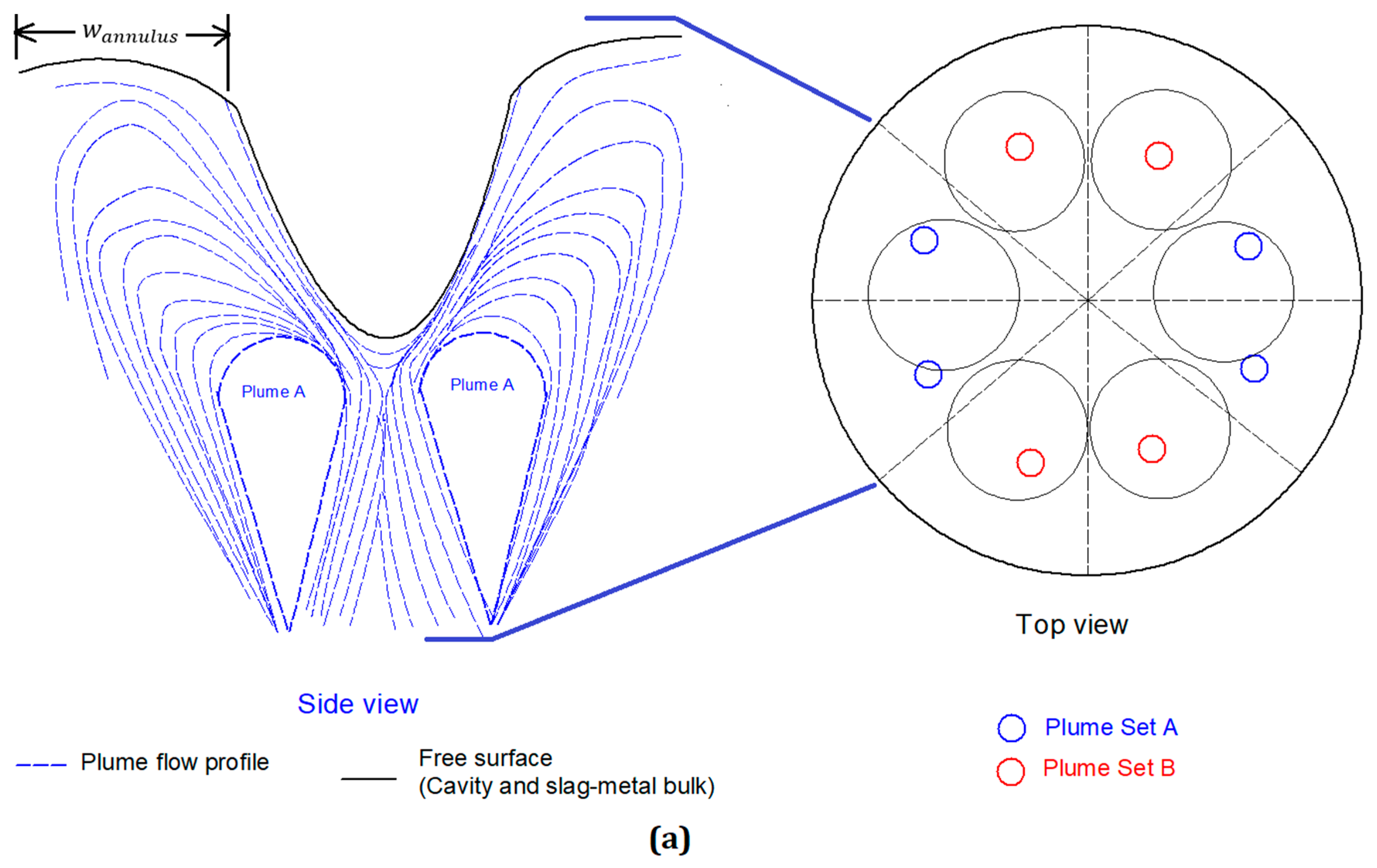
In ladles, single plumes are used to increase the mass transfer between slag and metal [51,52,53]. Contrary to a single gas-metal plume in a ladle, the emergence of bottom stirring plumes on a free surface is more complex. Based on locations of the bottom stirring plugs the plume may emerge to different locations on a free surface. In this study, the bottom stirred plug configuration is applied based on the data reported by Bertezzolo et al. [54] for the 200-t oxygen steelmaking furnace. The top view of this interaction between 8-bottom stirring plumes and a 6-holed lance for a 200-t oxygen steelmaking furnace is shown in Figure 2a,b. It should be noted that the intention of this figure is a schematic diagram to represent the assumption related to the plume-cavity interaction. The fluid flow profile is not computed by the authors. The interaction of the plumes with the cavities and the slag metal bulk is characterized on the basis of the following assumptions:
- The eight plumes are represented by a sub-sector of 45 degrees each. The downward circulating plumes do not affect the flow beyond their respective sub-sector.
- Each plume has a significant momentum and by virtue of that, undergoes complete radial expansion in its subsector. This leads to surface renewal and supply of metal to the gas-metal interface (cavities) and slag-metal interface (slag-metal bulk).
- Since only six cavities are created (by 6 holed lance), in contrast to the 8 bottom stirring plumes, the plumes are classified in two sets, namely:
- (Plume set A) 4 Partial expanded plumes: Two plumes are responsible for bringing liquid metal in contact with cavity. This leads to surface renewal of single cavity as shown in Figure 2a.
- (Plume set B) 4 Total expanded plumes: Each of the plumes causes surface renewal of the single cavity, as shown in Figure 2b
- The behavior of the plumes in the annular region surrounding the cavities is uniform in each sub-sector.
- The instantaneous dimension of the cavities can be calculated as a function of the lance parameters and from that the width of the annulus is calculated. These values are used to calculate the instantaneous refining in the respective zones.
- The metal flow resulting from the top-jet and the bottom stirring plumes is assumed to be additive, hence the surface renewal velocity is the sum of the top-jet and the bottom-stirring surface renewal velocities.
The solid lines in the figure represent the free surfaces (cavities, slag-metal bulk and vessel wall) whereas the dotted lines represent the plume flow profiles. The exact location of the porous plugs at the bottom is currently unknown and is based on bottom stirring configuration of the 200-t furnace being modeled in the study of Bertezzolo et al. [53].
The instantaneous density and composition differences between upper and lower baths are quite possible, but a large circulation of metal throughout the bath would reduce these gradients to a significant extent. A high bath circulation rate of 126 t/min (refer Appendix A) calculated in the current work for a 170–190 t bath indicates a high turnover of bath, thus decreasing these (density and composition) gradients and their effect on the metal flow behavior in a relatively short period of time. The concentration and temperature gradients can be neglected under the defined stirring conditions.
2.3. Determination of Mass Transfer at the Impact Zone
The mass transfer coefficient, k, can be defined according to Higbie’s penetration theory [55],
where is the diffusion coefficient of the reacting element , is the residence time of the reacting element at the impact zone/reaction interface and is defined by
where is the velocity of surface renewal, represents the ‘characteristic length’ and it is the half of the circumference (i.e., arc length) of the paraboloid cavity, since the surface renewal is assumed to be symmetric about the axis of the cavity. Based on the above stated assumptions the mass transfer coefficients at the impact zone and slag-metal bulk are calculated as shown in Table 1 and Table 2.
The values for the diffusion coefficients of Si and Mn in the liquid iron, which are determined from experimental studies [56,57,58] and compiled by Kawai and Shiraishi [59], are used in the current study. They range from to m2/s for Si (at 1550 °C–1725 °C) and to m2/s for Mn (at 1550 °C–1700 °C). However, another study by Grace and Derge [60] suggests that the values are ranging from to m2/s for Si and to m2/s for Mn in carbon saturated liquid iron. It is important to note that these values are one order of magnitude higher than those obtained from Calderon et al. [56], Majdic et al. [57] and Kawai et al. [58]. Since these sets of experimental values were arrived at independently, under different experimental conditions the values were used in the calculations contrary to those suggested by Grace and Derge [60].
2.4. Determination of Impact (Reaction) Area
In this study, the impact zone is defined as the smooth surface of the cavities formed by the supersonic jets from the lance, where the oxygen comes in contact with the metal bath. Previous studies [61,62,63,64] indicated that the cavity surface is rough, resulting in the generation of “splash sheets” [64] or “metal-bath spraying effect” [61]. However, the surface area enhancement due to splash sheet formation is difficult to estimate. Therefore, surface roughness is not included in the model development. In this study, the methodology by Dogan et al. [19] was adapted to calculate the impact area as follows.
The depth and diameter of the cavity are calculated using the correlation developed by Koria and Lange [65], for the penetrability of impinging oxygen jets in molten pig-iron baths. They found that these parameters were mainly affected by the oxygen supply pressure, nozzle diameter and the lance height which contribute to the momentum of gas jet. The following equations are used to calculate the depth and diameter of the cavity.
where is the lance height, is the throat diameter of lance’s nozzle, is the supply pressure of oxygen, is the ambient pressure inside the vessel, is the acceleration due to gravity, is the nozzle inclination angle. Then the area of single cavity, is calculated using the correlation
where is the radius of the cavity.
The total impact area of jets can be calculated by summation of individual cavities for multi-nozzle lances [2].
The slag-metal bulk is defined by the interface between the bath and slag at the annular region between the cavities and the wall of the furnace. It is evaluated by subtracting the total area of cavities from the cross-sectional area of the vessel.
The sequence of calculation for the refining model at the impact and slag-metal bulk zones is represented in Figure 3. For every time step, the data from hot metal and scrap composition such as manganese and silicon, metal-bath height, , lance height, , velocity of the oxygen jet at the impact point and bottom gas flow rate, with time are taken as inputs. The resultant cavity parameters and reaction areas (impact zone and slag-metal bulk) are then evaluated, followed by the calculation of the surface renewal velocities due to the top-jets and bottom-stirring separately as described in the previous section. The mass transfer coefficients at the two zones are calculated using Equation (11) while the refining rate at the two zones is calculated using Equation (1). Subsequently the composition of the bath is updated by taking into account the instantaneous bath weight , melted scrap weight , weight of solute removed and the sequence of calculation is repeated for the next time step.
3. Results and Discussion
3.1. Liquid Velocity
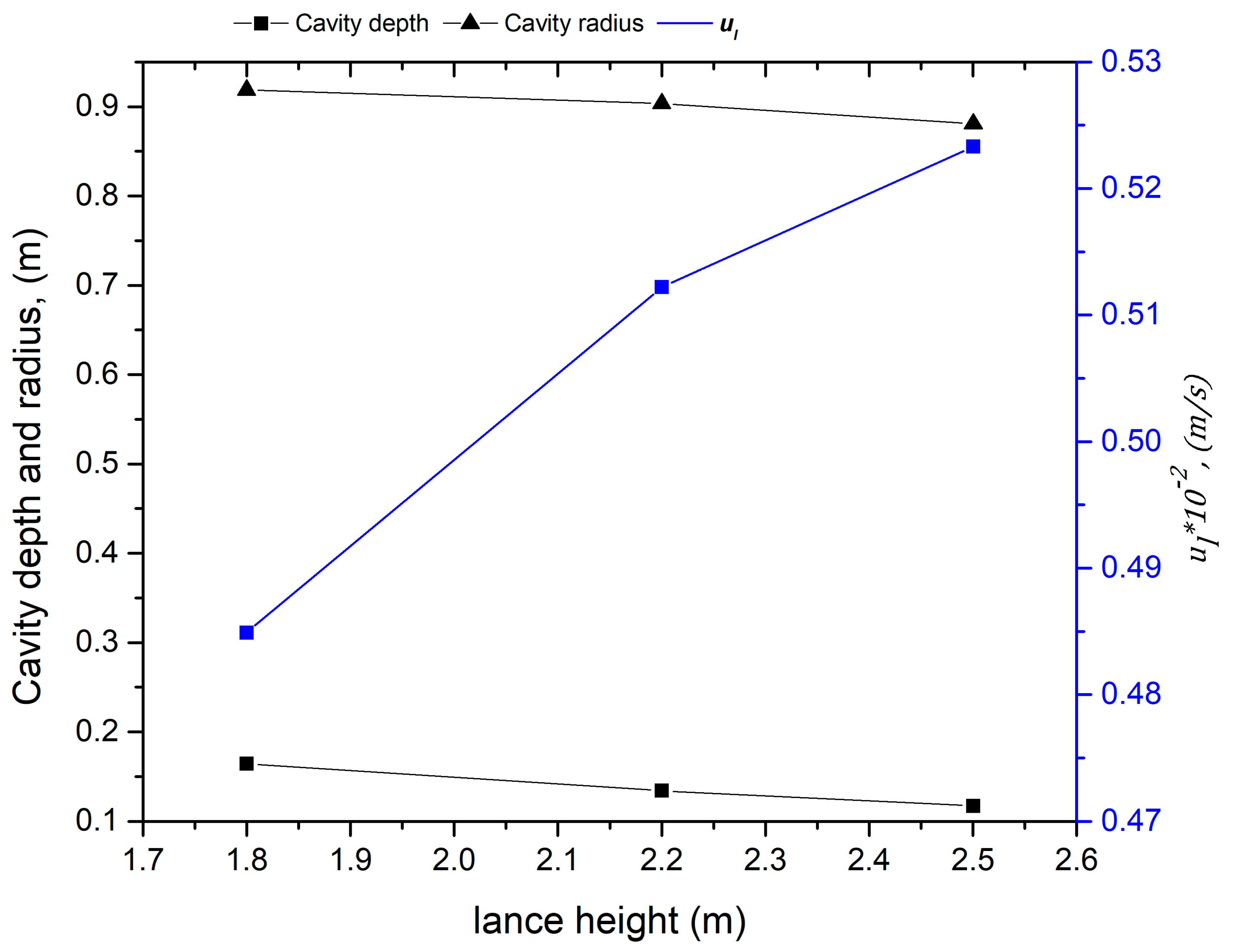
The surface renewal velocities at the impact zone were calculated with respect to time, considering the instantaneous blowing parameters for the operation of Cicutti et al. [4,5]. Figure 4 illustrates the variation of the surface renewal velocity due to the top-jet with respect to cavity dimensions at various lance heights prevalent during the blow. The decrease in lance height decreases the surface renewal velocity and increases the cavity depth and radius. The decrease in lance height would increase the momentum transferred by the oxygen jet to the cavity, which is expected, but this increased momentum supply is consumed in droplet generation and does not translate into an increase in surface renewal rate. This result is consistent with the literature. Hwang and Irons [43] also stated that the kinetic energy transfer (from the jet to the bath) was more efficient at higher lance heights based on their observation. The Energy Transfer Index (ETI) values for higher lance heights were higher than those for lower lance heights. The ETI is defined as a ratio between the kinetic energy of the bath and the input kinetic energy of the jet [43]. Similar observations were made in recent study by Zhou et al. [66] on kinetic energy dissipation by metal bath and slag in oxygen steelmaking vessels. For a 100-t oxygen steelmaking vessel they calculated the ETI value to decrease by 36%, when the lance height was lowered from 1.6 m to 1 m (for O2 flow rate of 3.76 ).
The surface renewal velocities due to the top jet, is compared with the surface renewal velocity due to bottom stirring, in Figure 5. The velocity of the metal circulation due to top jet varies from 0.0048 m/s to 0.0052 m/s and it is two orders of magnitude lower than the metal velocity at the top of the plume (0.45 to 0.64 m/s). Even though the characterization of metal flow is complex due to the overlap of the varying circulation patterns with respect to top-jet and plumes, this result shows that the plumes dominate the supply of metal to the cavities and the slag-metal bulk.
It should be noted that this model predicts a large quantity of metal (~126 t/min: procedure for the calculation described in Appendix A) is circulated by the bottom stirring plumes for a 200-t oxygen steelmaking furnace described by Cicutti et al. [4,5]. However, it is worth considering exactly how much of this metal comes into contact with oxygen from the jet or the slag.
3.2. Mass Transfer Coefficients
The values of mass transfer coefficients are calculated with respect to the process parameters such as lance height and bottom stirring gas flow rate. These parameters affect the cavity dimensions and the metal circulated coming in contact with the oxygen jet. The mass transfer coefficient at the cavities , related to liquid velocity due to the top jet varies from to m/s from start to end of the blow. If the contribution of both top-jet and bottom stirring plumes is considered, varies from to m/s. Similarly, the mass transfer coefficient at the slag-metal bulk due to the top jet varies from to m/s and for a combined contribution of top jet and bottom stirring plumes it varies from to m/s. This study shows that the magnitude of the mass transfer coefficients for the top jet is considerably lower than combined effect of top blowing and bottom stirring. This finding is consistent with literature [17,53,67,68].
It should be noted that the magnitudes are lower as compared with those reported in the literature. The values of mass transfer coefficients which have been reported by Ohguchi et al. [21], = m/s and = m/s (metal and slag phase mass transfer coefficients respectively, for gas stirred mass transfer between the two phases).
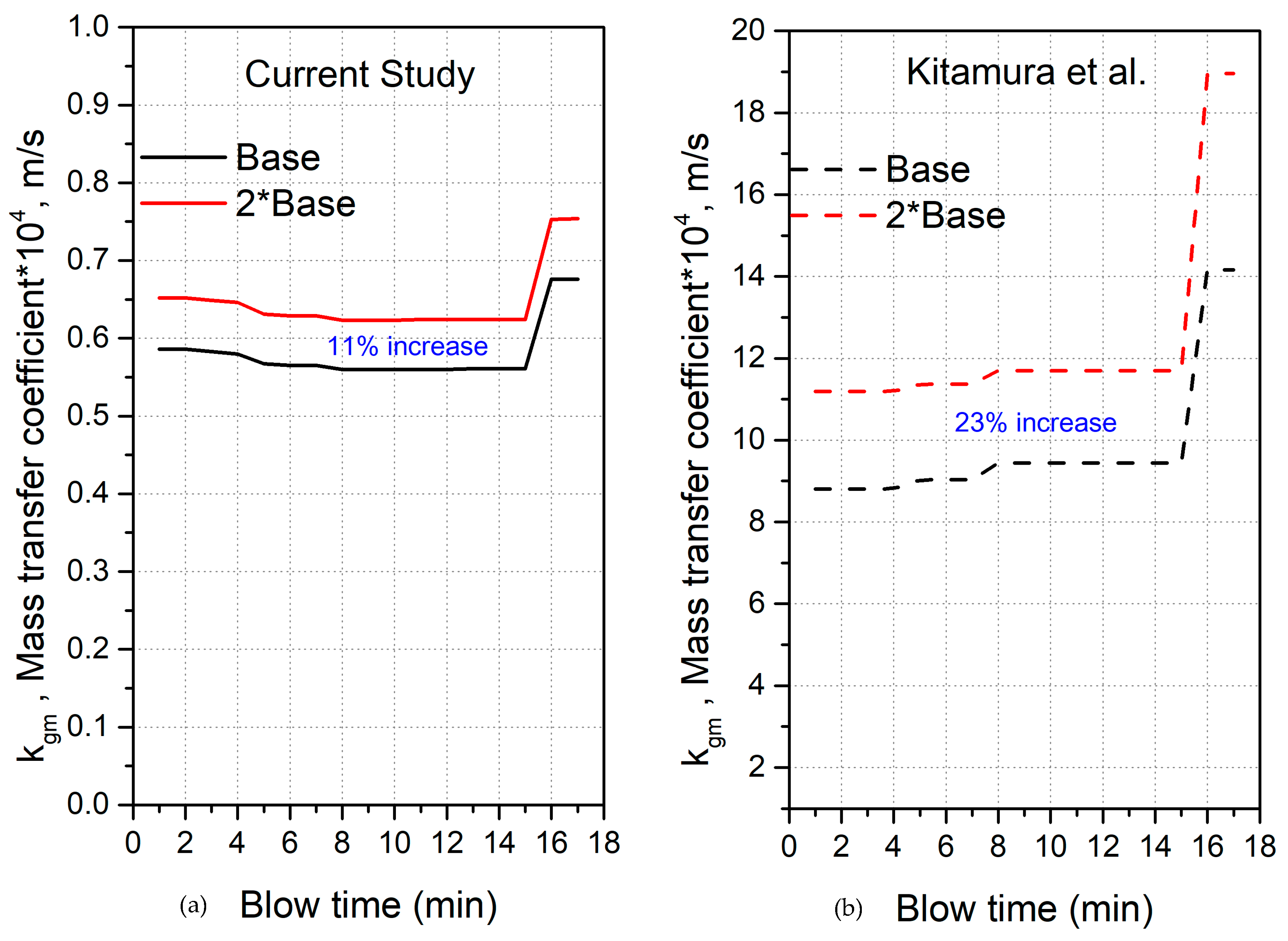
In Figure 6, the predictions of mass transfer coefficients at impact zone, from current study are compared with the values calculated though Kitamura et al.’s [20] approach for Cicutti et al.’s steelmaking operation (wherein the mass transfer coefficient varies as a function of stirring energy imparted on the bath through top-jet and bottom stirring gas). The mass transfer coefficients have been evaluated at two distinct bottom stirring flow rates, namely the base case of 2.5 Nm3/min and 5 Nm3/min. If the bottom stirring rate is doubled, an 11% increase in mass transfer coefficient is observed whereas in Kitamura et al.’s case the increase is 23%. The increase in bottom stirring rate would indeed increase the metal re-circulated per unit time (thus reducing the mixing time) but does not proportionately increase the metal reaching the interface. There is a limit to the metal coming in contact with the interfaces which is discussed in Section 3.3.
The values predicted by Kitamura et al. [20] are at-least one order of magnitude higher than those predicted in the current study. In Kitamura et al.’s [20] case the decrease in lance height translates to an increase in momentum transfer to the bath and a corresponding increase in mass transfer coefficient is observed. In the current study the magnitude of mass transfer coefficient decreases due to a decrease in lance height as discussed in the previous section. The increased supply of momentum is expended in droplet generation rather than agitation of bath. The sudden rise in mass transfer coefficients in the last 2 min of the blow is due to threefold increase in the bottom stirring rate (for bath homogenization).
3.3. Effect of Lance Height and Bottom Stirring on the Metal Circulation Rate at the Interfaces
As discussed in the previous section the metal circulating at the interfaces, MCRI, (cavities and slag-metal bulk) is calculated separately for each time step, based on the instantaneous mass transfer coefficient and areas and is given by the following equation.
Figure 7a shows the variation of total metal circulating at the interfaces and the instantaneous lance height and bottom stirring rates. The metal circulation rate at interfaces (MCRI) varies between 388 kg/min and 468 kg/min. As expected the MCRI shows a similar dependence on the lance height as shown by the mass transfer coefficient. The bottom stirring rate affects this parameter significantly. The lowered lance height represents a harder blow as shown in Figure 7b. This figure indicates that there is a marginal change as compared to the base case. On the other hand, doubling the bottom stirring rate increases the MCRI and it varies from 446 kg/min to 523 kg/min as shown in Figure 7c. The cross-sectional area of the plume increases successively as it rises towards the top of the metal bath. However, regardless of the mode of emergence of the plume on the free surface, the plume is able to circulate the metal across a larger area, where metal (and consequently the impurities like C, Si and Mn) comes in contact with oxygen from either the jet or FeO in slag.
It should be noted that the un-melted scrap most likely interacts with the plumes depending on scrap dimensions. Consequently, fluid flow at the impact and slag-metal bulk zones may also be affected by the presence of un-melted scrap. However, to the best of authors’ knowledge, there is no study available for the effects of un-melted scrap on the fluid flow behavior as well as mass transfer of solutes in the open literature. Therefore, the interaction of un-melted scrap with the rising plume is not considered in the current study.
3.4. Refining Rates at the Interface
The change in bath weight during the blow was calculated by an approach previously suggested by Dogan et al. [28,29]. This involves accounting for the instantaneous amount of scrap freezing/melting , droplet ejected and droplet returned to the bath and metal consumed in slag formation , as indicated in Equation (18)
The change in bath and scrap masses for Cicutti et al.’s operation is shown in Figure 8. There is a minor decrease in metal bath weight in the first 2 min of the blow due to the freezing of metal on the surface of cold scrap and a corresponding rise in scrap weight. Subsequently the scrap melts steadily and the bath weight increases linearly. There is a minor change in the bath weight after scrap is fully melted.
Figure 9 compares the effect of top oxygen jets and combined blow (top oxygen jets + bottom stirring plumes) on the oxidation rates of silicon and manganese in the liquid metal at the cavities and the slag-metal bulk (as described in the combined refining model in Figure 3). The refining model predicts oxidation throughout the blow. Si content in the metal is observed to decrease in the early part of the blow, primarily due to a reduction in bath weight (due to freezing of metal on scrap). During the later part of the blow, there is a negligible change due to an increase in bath weight, even though oxidation continues to occur. A similar trend is observed for refining of Mn from liquid metal. There is hardly any oxidation of silicon and manganese taking place due to top oxygen jets. This is most likely due to the fact that surface renewal velocity is very small and hence only a marginal momentum of the oxygen jets is transferred to the bath.
Figure 10 compares the predicted concentration of silicon and manganese in the metal to the measured values reported in the study of Cicutti et al. [4,5]. The calculated values are significantly higher than the measured values due to low refining rates at the impact and slag-metal bulk zones. The value of product of mass transfer coefficient and reaction area () should be 50–100 times higher if the impact and slag-metal bulk zones are considered as major refining zones. This indicates that the contribution of these reaction zones is insignificant. The authors are currently working on the calculation of refining rates in other possible reaction zones. It is still important to identify the possible sources of such a low prediction. It is worth considering how the selection of diffusion coefficient values from literature would affect the refining rate predictions. The lower diffusion coefficient values by Grace and Derge [54] (discussed in Section 2.3) will affect the mass transfer coefficients to an extent, however the mass transfer rates don’t increase significantly and there is no appreciable increase in the refining rates (the predicted final silicon content decreases from 0.2758 wt % to 0.25 wt %.
Figure 11 shows the variations in the area of the impact zone and the slag-metal bulk zone and the individual contributions to the refinement of silicon. The area of the impact zone increases as the lance height decreases. Therefore, the slag-metal bulk area decreases. The refining rate of silicon is affected proportionately. The silicon refining rate falls between minutes 2 and 4 due to a decrease in the weight of the metal bath. It can be inferred from this figure that a change in lance height will vary the areas of cavities and slag-metal bulk, but this will not significantly increase the refining in the corresponding reaction zones.
Another possible reason for the low predictions might be a small gas-metal reaction interface which is related to the assumption that the cavity surface is smooth (approximately 15 m2). If the surface area of the impact zone rises by a factor of 10 (by assuming roughness due to splash sheet formation), the corresponding increase in the silicon refining rate is shown in Figure 12. The final silicon content goes down to 0.20 wt % if the surface roughness is considered, but it still cannot explain the rapid oxidation of silicon during the initial part of the blow. It is worth mentioning about the hot-model study by Koch et al. [61]. They conducted experiments which involved the blowing of an oxygen jet on a 50 kg molten Fe-C bath to simulate the top-blown oxygen steelmaking process. The generated droplets due to “metal-bath spraying” at the cavity were sampled at various points of the cross section of the metal sampler during a blow. The authors observed that at any given instant, the droplets had lower carbon content than the metal bath. Further the “inner” droplets (ejected into the jet) experienced much higher decarburization as compared to the “outer” droplets (ejected away from jet). This indicates a possibility of significant contribution of decarburization and other refining reactions via the gas-metal droplet interface rather than the smooth cavity surfaces.
As discussed in the section above, the flow of bottom stirring plumes to the top causes the circulation of metal. Additionally there is an escape of argon bubbles through the slag-metal interface as argon solubility in the metal is very low. During the passage of the bubble into the slag, a thin film of metal is carried over, and the drainage of this film causes the suspension of metal droplets in slag. This phenomena of the passage of argon bubbles through the liquid iron-slag interface has been investigated using an in situ X-ray transmission technique [69,70] as well as mathematical modelling [71]. These studies described the effect of bubble size and interfacial tension between slag-metal on the metal suspended in slag. However, the typical observed [69] mass of ejection/entrainment of metal in the slag phase was extremely low (0.0065 g/bubble for surface tension of 1.8 N/m and bubble diameter of 11.5 mm). This would entail an ejection of 2.55 kg metal/min for Cicutti et al.’s [4] bottom stirring rate of 2.5 Nm3/min. This indicates a much lower contribution of refining through this mechanism.
4. Conclusions
A mechanistic description of the refining phenomena at the impact and the slag-metal bulk zones is presented. This description includes the role of the oxygen jets and bottom stirring plumes in bringing the metal into contact with oxygen, using independent models for each.
- Top-blown jets appear to cause a negligible renewal of the surface at the impact zone despite their high momentum. This leads to the conclusion that this momentum is expended in the generation of droplets.
- The bottom stirring plumes cause a significant circulation of metal (~125 tonne/min for 2.5 m3 stirring gas/min in 200-t furnace) but do not aid the refining reactions at the impact and the slag-metal bulk zones.
- The contribution of the impact and slag-metal bulk zones appear to be negligible in the refining reactions while the emulsion zone appears to be a significant contributor to the refining reactions.
Author Contributions
Supervision, N.D.; Formulation of model, A.K. and N.D.; Review, N.D.; Editing, A.K. and N.D.; A.K. wrote the original draft of paper.
Funding
This research was funded by Natural Sciences and Engineering Research Council of Canada (NSERC), project number 20007117 and the McMaster Steel Research Centre (SRC).
Acknowledgments
The authors would like to thank Gordon Irons and Anand Senguttuvan for the valuable discussions regarding this work.
Conflicts of Interest
The authors declare no conflict of interest.
Nomenclature
| Area of single cavity, | |
| Total area of cavities/impact zone, | |
| Area between bulk slag and metal bath, | |
| Circumference of cavity, | |
| Diffusion coefficient of impurity in hot-metal, | |
| Diameter of cavity, | |
| Throat diameter of nozzle, | |
| Height of metal bath, | |
| Lance height, | |
| Moles of solute transferred to interface, | |
| Mass transfer coefficient, | |
| Mass transfer coefficient of solute X at the impact zone/gas-metal interface, | |
| Mass transfer coefficient of solute X at the slag-metal interface, | |
| Distribution coefficient of silicon between hot-metal and slag | |
| Characteristic length of cavity, | |
| Characteristic length of slag-metal interface, | |
| Metal circulating at the interfaces, | |
| Molecular weight of solute X, | |
| Number of bottom stirring elements i.e., number of plumes | |
| Number of cavities | |
| Depth of cavity, | |
| Ambient pressure inside vessel, | |
| Oxygen supply pressure, | |
| Bottom stirring gas flow rate, | |
| Radius of cavity, | |
| Time instant and time step, respectively | |
| Residence time of an element at interface, m/s | |
| surface renewal velocity due to bottom stirring, m/s | |
| Tangential velocity of oxygen jet, m/s | |
| Velocity of oxygen jet at impact point, m/s, | |
| Surface renewal velocity of hot-metal due to oxygen jet, m/s | |
| Volume of metal circulated, | |
| Weight of metal bath, kg | |
| Weight of melted scrap, kg | |
| Weight of solute X (silicon and manganese) removed, | |
| Weight of droplets ejected from the bath, | |
| Weight of droplets returning to the bath, | |
| Weight of hot metal oxidized, | |
| Width of annular region between cavity and vessel walls, | |
| Solute in hot-metal like Si or Mn | |
| Inclination angle of the nozzle, () | |
| Cavity angle (cavity slope), () | |
| Density of hot-metal, |
Appendix A
The metal circulation for Cicutti et al. data is calculated as follows:
For 8 bottom stirring plug.
Bottom stirring gas flow rate = 150 Nm3/h (for entire blow except last two minutes).
Bottom stirring gas flow rate, Q = 150/3600/8 = 0.005208 Nm3/s/plug.

Table A1.
Process parameters.
| Q, m3/s | 0.005208 |
| H (height of metal bath), m | 0.89 |
The value of the metal circulated by the plume (bottom stirred gas) is calculated by Equations (7) through (10).
Table A2.
Calculation of metal circulation by single plume.
| Q* | z* | Ap, m2 | Metal Circulated by Single Plume, kg/min | |||
|---|---|---|---|---|---|---|
| 0.002225 | 1 | 0.1642 | 0.4854 | 0.0773 | 0.0375 | = 15774.98 |
So total metal circulated by 8 bottom stirring plumes (MCRI) = 15774 × 8 = 126,199.8 kg/min.
References
- Miller, T.W.; Jimenez, J.; Sharan, A.; Goldstein, D.A. The Making, Shaping and Treating of Steel, 11th ed.; Carnegie Steel Company: Pittsburgh, PA, USA, 1998. [Google Scholar]
- Deo, B.; Boom, R. Fundamentals of Steel Making Metallurgy; Pretince Hall International: Upper Saddle River, NJ, USA, 1993. [Google Scholar]
- Pehlke, R.D. Steelmaking—The jet age. Metall. Trans. B 1980, 11, 539–562. [Google Scholar] [CrossRef]
- Cicutti, C.; Valdez, M.; Pérez, T.; Petroni, J.; Gomez, A.; Donayo, R.; Ferro, L. Study of slag-metal reactions in an LD-LBE converter. In Proceedings of the 6th International Conference on Molten Slags, Fluxes and Salts, Helsinki, Finland, 12–17 June 2000; p. 367. [Google Scholar]
- Cicutti, C.; Valdez, M.; Pérez, T.; Donayo, R.; Petroni, J. Analysis of slag foaming during the operation of an industrial converter. Lat. Am. Appl. Res. 2002, 32, 237–240. [Google Scholar]
- van Hoorn, A.I.; van Konynenburg, J.T.; Kreyger, P.J. Evolution of slag composition and weight during the blow. In The Role of Slag in Basic Oxygen Steelmaking Processes, McMaster Symposium on Iron and Steelmaking No.4; McMaster University: Hamilton, ON, Canada, 1976. [Google Scholar]
- Meyer, H.W.; Porter, W.F.; Smith, G.; Szekely, J. Slag-Metal Emulsions and Their Importance in BOF Steelmaking. J. Met. 1968, 20, 35–42. [Google Scholar] [CrossRef]
- Schoop, J.; Resch, W.; Mahn, G. Reactions Occuring During the Oxygen Top-Blown Process and The Calculation of Metallurgical Control Parameters. Ironmak. Steelmak. 1978, 2, 72–79. [Google Scholar]
- Asai, S.; Muchi, I. Theoretical Analysis by the Use of Mathematical Model in LD Converter Operation. Trans. ISIJ 1970, 10, 250. [Google Scholar]
- Jalkanen, H. Experiences in physicochemical modelling of oxygen converter process(BOF). Sohn Int. Symp. Adv. Process. Met. Mater. 2006, 2, 541–554. [Google Scholar]
- Jalkanen, H.; Holappa, L. On the role of slag in the oxygen converter process. In Proceedings of the VII International Conference on Molten Slags Fluxes and Salts, Cape Town, South Africa, 25–28 January 2004; pp. 71–76. [Google Scholar]
- Sarkar, R.; Gupta, P.; Basu, S.; Ballal, N.B. Dynamic Modeling of LD Converter Steelmaking: Reaction Modeling Using Gibbs’ Free Energy Minimization. Metall. Mater. Trans. B 2015, 46, 961–976. [Google Scholar] [CrossRef]
- Rout, B.K.; Brooks, G.A.; Li, Z.; Rhamdhani, A. Dynamic Modeling of Oxygen Steelmaking Process: A Multi-Zone Kinetic Approach. AISTech 2017, 2017, 1315–1326. [Google Scholar]
- Rout, B.K.; Brooks, G.A.; Li, Z.; Rhamdhani, M.A. Analysis of Desiliconization Reaction Kinetics in a BOF. AISTech 2016, 2016, 1019–1026. [Google Scholar]
- Knoop, W.V.D.; Deo, B.; Snoijer, A.B.; Unen, G.V.; Boom, R. A Dynamic Slag-Droplet Model for the Steelmaking Process. In Proceedings of the 4th International Conference on Molten Slags and Fluxes, Sendai, Japan, 8–11 June 1992; pp. 302–307. [Google Scholar]
- Jung, I.H.; Hudon, P.; van Ende, M.A.; Kim, W.Y. Thermodynamic Database for P2O5 Containing Slags and Its Application to the Dephosphorisaing process. AISTech Proc. 2014, 2014, 1257–1268. [Google Scholar]
- Nakanishi, K.; Saito, K.; Nozaki, T.; Kato, Y.; Suzuki, K.; Emi, T. Physical and Metallurgical Characteristics of Combined Processes. In Proceedings of the 65th Steelmaking Conference Proceedings, Pittsburgh, PA, USA, 28–31 March 1982; pp. 101–108. [Google Scholar]
- Price, D.J. Steelmaking: Significance of the emulsion in carbon removal. In Proceedings of the Process Engineering of Pyrometallurgy Symposium, London, UK, 8–15 January 1974; pp. 8–15. [Google Scholar]
- Dogan, N.; Brooks, G.A.; Rhamdhani, M.A. Comprehensive Model of Oxygen Steelmaking Part 3: Decarburization in Impact Zone. ISIJ Int. 2011, 51, 1102–1109. [Google Scholar] [CrossRef] [Green Version]
- Kitamura, S.; Kitamura, T.; Shibata, K.; Mizukami, Y.; Mukawa, S.; Nakagawa, J. Effect of Stirring Energy, Temperature and Flux Composition on Hot Metal Dephosphorization Kinetics. ISIJ Int. 1991, 31, 1322–1328. [Google Scholar] [CrossRef]
- Ohguchi, S.; Robertson, D.G.; Deo, B.; Grieveson, P.; Jeffes, J.H. Simultaneous dephosphorization and desulfurization of molten pig iron. Ironmak. Steelmak. 1984, 11, 202–213. [Google Scholar]
- Chen, E. Kinetic study of Droplet Swelling in BOF steelmaking. Ph.D Thesis, McMaster University, Hamilton, ON, Canada, 2011. [Google Scholar]
- Chen, E.; Coley, K.S. Kinetic study of droplet swelling in BOF steelmaking. Ironmak. Steelmak. 2010, 37, 541–545. [Google Scholar] [CrossRef]
- Coley, K.S.; Chen, E.; Pomeroy, M. Kinetics of reaction important in oxygen steelmaking. In Proceedings of the Extraction and Processing Division Symposium on Pyrometallurgy, San Diego, CA, USA, 16–20 June 2014; pp. 289–302. [Google Scholar]
- Pomeroy, M.D. Decarburization Kinetics of Fe-C-S Droplets in Oxygen Steelmaking Slags. Master’s Thesis, McMaster University, Hamilton, ON, Canada, 2011. [Google Scholar]
- Gu, K.; Dogan, N.; Coley, K.S. The Influence of Sulfur on Dephosphorization Kinetics Between Bloated Metal Droplets and Slag Containing FeO. Metall. Mater. Trans. B 2017, 48, 2343–2353. [Google Scholar] [CrossRef] [Green Version]
- Gu, K.; Dogan, N.; Coley, K.S. An Assessment of the General Applicability of the Relationship Between Nucleation of CO Bubbles and Mass Transfer of Phosphorus in Liquid Iron Alloys. Metall. Mater. Trans. B 2018, 49, 1119–1135. [Google Scholar] [CrossRef]
- Dogan, N. Mathematical Modelling of Oxygen Steelmaking. Ph.D Thesis, Swinburne University, Hawthorn, VIC, Australia, 2011. [Google Scholar]
- Dogan, N.; Brooks, G.A.; Rhamdhani, M.A. Comprehensive Model of Oxygen Steelmaking Part 1: Model Development and Validation. ISIJ Int. 2011, 51, 1086–1092. [Google Scholar] [CrossRef] [Green Version]
- Dogan, N.; Brooks, G.A.; Rhamdhani, M.A. Comprehensive Model of Oxygen Steelmaking Part 2: Application of Bloated Droplet Theory for Decarburization in Emulsion Zone. ISIJ Int. 2011, 51, 1093–1101. [Google Scholar] [CrossRef] [Green Version]
- Masui, A.; Yamada, K.; Takahashi, K. Slagmaking, Slag/metal reactions and their sites in BOF refining processes. In The Role of Slag in Basic Oxygen Steelmaking Processes, McMaster Symposium on Iron and Steelmaking No.4; McMaster University: Hamilton, ON, Canada, 1976. [Google Scholar]
- Narita, K.; Makino, T.; Matsumoto, H.; Hikosaka, A.; Katsuda, J. Oxidation Mechanism of Silicon in Hot Metal. Tetsu-to-Hagane 1983, 69, 1722–1733. [Google Scholar] [CrossRef]
- Suito, H.; Inoue, R. Thermodynamic Assessment of Manganese Distribution in Hot Metal and Steel. ISIJ Int. 1995, 35, 266–271. [Google Scholar] [CrossRef]
- Rout, B.; Brooks, G.; Rhamdhani, M.A.; Li, Z.; Schrama, F.N.; Sun, J. Dynamic Model of Basic Oxygen Steelmaking Process Based on Multi-zone Reaction Kinetics: Model Derivation and Validation. Metall. Mater. Trans. B 2018, 49, 537–557. [Google Scholar] [CrossRef]
- Simotsuma, T.; Sano, K. The Influence of Spouting by Bath Motion. Tetsu-to-Hagane 1965, 51, 1909. [Google Scholar]
- Sharma, S.K.; Hlinka, J.W.; Kern, D.W. The Bath Circulation, Jet Penetration and High Temperature Reaction Zone in BOF Steelmaking. In Proceedings of the InOpen Hearth and Basic Oxygen Steel Conference, Pittsburgh, PA, USA, 17–20 April 1977; pp. 187–197. [Google Scholar]
- Davenport, W.G.; Wakelin, D.; Bradshaw, A. Interaction of both bubbles and gass jets with liquids. Heat Mass Transf. Process Metall. 1967, 24, 207–245. [Google Scholar]
- Odenthal, H.; Falkenreck, U.; Schlüter, J. CFD Simulation of Multiphase Melt Flows in Steelmaking Converters. In Proceedings of the European Conference on Computational Fluid Dynamics, Egmond aan Zee, The Netherlands, 5–8 September 2006. [Google Scholar]
- Odenthal, H.; Kempken, J.; Schlüter, J.; Emling, W.H. Advantageous numerical simulation of the converter blowing process. Iron Steel Technol. 2007, 4, 71–89. [Google Scholar]
- Odenthal, H. Latest Developments for the BOF Converter. In Proceedings of the 6th International Congress on the Science and Technology of Steelmaking, Beijing, China, 12–14 May 2015. [Google Scholar]
- Li, Y.; Lou, W.T.; Zhu, M.Y. Numerical simulation of gas and liquid flow in steelmaking converter with top and bottom combined blowing. Ironmak. Steelmak. 2013, 40, 505–514. [Google Scholar] [CrossRef]
- Ersson, M.; Höglund, L.; Tilliander, A.; Jonsson, L.; Jönsson, P. Dynamic Coupling of Computational Fluid Dynamics and Thermodynamics Software: Applied on a Top Blown Converter. ISIJ Int. 2008, 48, 147–153. [Google Scholar] [CrossRef] [Green Version]
- Hwang, H.Y.; Irons, G.A. A water model study of impinging gas jets on liquid surfaces. Metall. Mater. Trans. B Process Metall. Mater. Process. Sci. 2012, 43, 302–315. [Google Scholar] [CrossRef]
- He, Q.L.; Standish, N. A Model Study of Droplet Generation in the BOFSteelmaking. ISIJ Int. 1990, 30, 305–309. [Google Scholar] [CrossRef]
- Luomala, M.J.; Fabritius, T.M.J.; Härkki, J.J. The Effect of Bottom Nozzle Configuration on the Bath Behaviour in the BOF. ISIJ Int. 2004, 44, 809–816. [Google Scholar] [CrossRef] [Green Version]
- Maia, B.T.; Imagawa, R.K.; Tavares, R.P. Cold Model Bath Behavior Study in LD Converter With Bottom Blowing. AISTech 2016, 55, 1083–1094. [Google Scholar]
- Maia, B.T.; Diniz, C.N.A.; Carvalho, D.A.; Souza, D.L.D.; Guimarães, J.A.; Raissa, S. TBM Tuyeres Arrangements and Flow—Comparison Between BOF thyssenkrupp CSA and Cold Model. AISTech 2017, 2017, 1335–1346. [Google Scholar]
- Krishnapisharody, K.; Irons, G.A. An Analysis of Recirculatory Flow in Gas-Stirred Ladles. Steel Res. Int. 2010, 81, 880–885. [Google Scholar] [CrossRef]
- Sano, M.; Mori, K. Fluid Flow and Mixing Characteristics in a Gas-stirred Molten Bath. Trans. Iron Steel Inst. Jpn. 1983, 23, 169–175. [Google Scholar] [CrossRef]
- Murthy, G.G.K.; Ghosh, A.; Mehrotra, S.P. Characterization of two-phase axisymmetric plume in a gas stirred liquid bath-A water model study. Metall. Trans. B 1988, 19, 885–892. [Google Scholar] [CrossRef]
- Szekely, J.; Lehner, T.; Chang, C. Flow phenomena, mixing, and mass transfer in argon stirred ladles. Ironmak. Steelmak. 1979, 6, 285. [Google Scholar]
- Hsiao, C.; Lehner, T. Fluid Flow in Ladles-Experimental Results. Scand. J. Metall. 1980, 9, 105–110. [Google Scholar]
- Nakanishi, K.; Fujii, T.; Szekely, J. Possible relationship between energy dissipation and agitation in steel processing operations. Ironmak. Steelmak. 1975, 2, 193. [Google Scholar]
- Bertezzolo, U.; Donayo, R.; Gomez, A.; Denier, G.; Stomp, H. The LBE process at Siderar. In Proceedings of the 2nd European Oxygen Steelmaking Congress, Taranto, Italy, 13–15 October 1997. [Google Scholar]
- Higbie, R. The rate of absorption of a pure gas into a still liquid during short periods of exposure. Trans. Am. Inst. Chem. Eng. 1935, 35, 36–60. [Google Scholar]
- Calderon, F.; Sano, N. Diffusion of Mn and Si in liquid Fe over the whole range of composition. Metall. Trans. B 1971, 2, 3325. [Google Scholar] [CrossRef]
- Majdic, A.; Graf, D.; Schenk, J. Diffusion of Si,P,S and Mn in molten Fe. Arch. für das Eisenhüttenwes 1969, 40, 627. [Google Scholar]
- Saito, T.; Kawai, Y.; Maruya, K. Diffusion of Some Alloying Elements in Liquid Iron. Tohuku Daigaku Senk. 1960, 16, 15. [Google Scholar]
- Kawai, Y.; Shiraishi, Y. Handbook of Physico-Chemical Properties at High Temperatures; Iron and Steel Institute of Japan: Tokyo, Japan, 1988. [Google Scholar]
- Grace, R.; Derge, G. Diffusion of Third Elements in Liquid Iron Saturated with Carbon. Trans. Metall. Soc. 1958, 212, 331–337. [Google Scholar]
- Koch, K.; Falkus, J.; Ralf, B. Hot model experiments of the metal bath spraying effect during the decarburization of Fe-C melts through oxygen top blowing. Steel Res. Int. 1993, 64, 15–21. [Google Scholar] [CrossRef]
- Lee, M.; Whitney, V.; Molloy, N. Jet-liquid interaction in a steelmaking electric arc furnace. Scand. J. Metall. 2001, 30, 330–336. [Google Scholar] [CrossRef]
- Lee, M.S.; O’Rourke, L.; Molloy, N.A. Oscillatory flow in the steelmaking vessel. Scand. J. Metall. 2003, 32, 281–288. [Google Scholar] [CrossRef]
- Sabah, S.; Brooks, G.A. Splash Distribution in Oxygen Steelmaking. Metall. Mater. Trans. B 2014, 46, 863–872. [Google Scholar] [CrossRef]
- Koria, S.; Lange, K.W. Penetrability of impinging gas jets in molten steel bath. Steel Res. 1987, 58, 421–426. [Google Scholar] [CrossRef]
- Zhou, X.; Ersson, M.; Zhong, L.; Jönsson, P. Numerical Simulations of the Kinetic Energy Transfer in the Bath of a BOF Converter. Metall. Mater. Trans. B Process Metall. Mater. Process. Sci. 2016, 47, 434–445. [Google Scholar] [CrossRef]
- Koria, S. Studies of the Bath Mixing Intensity in converter Steelmaking Processes. Can. Metall. Q. 1992, 31, 105–112. [Google Scholar] [CrossRef]
- Koria, S.; Pal, S. Experimental study of the effect of gas injection parameters on bath mixing intensity induced during steelmaking. Steel Res. 1991, 2, 47–53. [Google Scholar] [CrossRef]
- Han, Z.; Holappa, L. Bubble Bursting Phenomenon in Gas/Metal/Slag Systems. Metall. Mater. Trans. B 2003, 34, 525–532. [Google Scholar] [CrossRef]
- Han, Z.; Holappa, L. Mechanisms of Iron Entrainment into Slag due to Rising Gas Bubbles. ISIJ Int. 2003, 43, 292–297. [Google Scholar] [CrossRef]
- Kobayashi, S. lron Droplet Formation Due to Bubbles Passing through Molten lron/Slag Interface. ISIJ Int. 1993, 33, 577–582. [Google Scholar] [CrossRef]
Figure 1.
Fluid flow behavior at impact zone by gas jet impingement. Reproduced from [3,35], with permission of Springer, 1980. are vertical velocity at the impingement point, tangential velocity of gas-jet, and surface renewal velocity of the metal bath due to oxygen jet and bottom stirring plumes, respectively. > >> . In the current model the surface renewal velocity due to top jet bottom stirring plumes is .

Figure 2.
Schematic representation of the interaction between cavities and plumes (a) Expansion of plume set A underneath cavities (Side view), (b) Expansion of plume set B underneath cavities (Side view).
Figure 2.
Schematic representation of the interaction between cavities and plumes (a) Expansion of plume set A underneath cavities (Side view), (b) Expansion of plume set B underneath cavities (Side view).


Figure 3.
Schematic representation of calculation procedure for refining model.

Figure 4.
Change of cavity dimensions and surface velocity at various lance heights.

Figure 5.
Comparison of surface renewal velocities due to top-jet and bottom stirring, (h = lance height, m).
Figure 5.
Comparison of surface renewal velocities due to top-jet and bottom stirring, (h = lance height, m).

Figure 6.
Comparison of metal phase mass transfer coefficients calculated by (a) Current model and (b) correlation obtained from the study of Kitamura et al. [20].
Figure 6.
Comparison of metal phase mass transfer coefficients calculated by (a) Current model and (b) correlation obtained from the study of Kitamura et al. [20].

Figure 7.
Effect of lance height and stirring rate on metal circulated at cavities and slag-metal bulk. (a) Base case (for operation of Cicutti et al., (b) Harder blow i.e., consistently lower lance height (2.2 m/1.9 m/1.6 m), (c) Excess stirring rate: 5 m3/s (0–15 min), 16.66 m3/s (16–17 min).
Figure 7.
Effect of lance height and stirring rate on metal circulated at cavities and slag-metal bulk. (a) Base case (for operation of Cicutti et al., (b) Harder blow i.e., consistently lower lance height (2.2 m/1.9 m/1.6 m), (c) Excess stirring rate: 5 m3/s (0–15 min), 16.66 m3/s (16–17 min).


Figure 9.
Effect of top and combined blows on the silicon and manganese oxidation rates during oxygen blow.
Figure 9.
Effect of top and combined blows on the silicon and manganese oxidation rates during oxygen blow.

Figure 10.
Comparison of measured and predictions for silicon and manganese in the liquid metal.

Figure 11.
Variation of area and contribution to refining by impact and slag-metal bulk zones.

Figure 12.
Effect of surface roughness on oxidation rate of silicon.

Table 1.
Evaluation of mass transfer parameters at impact zone (gas-metal interface).
| Plume Set | Reaction Area, m2 | Characteristic Length, m | Time of Contact, s | Mass Transfer Coefficient, m/s |
|---|---|---|---|---|
| A | ||||
| B |
where = Total area of cavities (gas-metal interfacial area), ) represents area of a single cavity and = Circumference of the cavity. It should be noted that and are calculated using Equations (6) and (10).
Table 2.
Evaluation of mass transfer parameters at slag-metal bulk (slag-metal interface).
| Reaction Area, m2 | Characteristic Length, m | Time of Contact, s | Mass Transfer Coefficient, m/s |
|---|---|---|---|
where = Area of slag-metal bulk, m2, = Width of annulus between cavities and wall of vessel.
© 2019 by the authors. Licensee MDPI, Basel, Switzerland. This article is an open access article distributed under the terms and conditions of the Creative Commons Attribution (CC BY) license (http://creativecommons.org/licenses/by/4.0/).
Share and Cite
MDPI and ACS Style
Kadrolkar, A.; Dogan, N. Model Development for Refining Rates in Oxygen Steelmaking: Impact and Slag-Metal Bulk Zones. Metals 2019, 9, 309. https://doi.org/10.3390/met9030309
AMA Style
Kadrolkar A, Dogan N. Model Development for Refining Rates in Oxygen Steelmaking: Impact and Slag-Metal Bulk Zones. Metals. 2019; 9(3):309. https://doi.org/10.3390/met9030309
Chicago/Turabian StyleKadrolkar, Ameya, and Neslihan Dogan. 2019. "Model Development for Refining Rates in Oxygen Steelmaking: Impact and Slag-Metal Bulk Zones" Metals 9, no. 3: 309. https://doi.org/10.3390/met9030309
Note that from the first issue of 2016, this journal uses article numbers instead of page numbers. See further details here.