Article

Characterisation and Comparison of Process Chains for Producing Automotive Structural Parts from 7xxx Aluminium Sheets

1
LKR Light Metals Technologies, Austrian Institute of Technology, Lamprechtshausener Strasse 61, 5282 Ranshofen, Austria
2
Institute of Materials Science, Joining and Forming, Graz University of Technology, Kopernikusgasse 24, 8010 Graz, Austria
3
Chair of Materials Science, University of Rostock, Albert-Einstein-Strasse 2, 18051 Rostock, Germany
4
Magna Steyr Fahrzeugtechnik AG & Co KG, CoC Material & Process Engineering, Liebenauer Hauptstrasse 317, 8041 Graz, Austria
*
Author to whom correspondence should be addressed.
Metals 2019, 9(3), 305; https://doi.org/10.3390/met9030305
Submission received: 11 February 2019 / Revised: 26 February 2019 / Accepted: 28 February 2019 / Published: 7 March 2019

Abstract

:
Due to their high specific strength, EN AW-7xxx aluminium alloys are promising materials for reducing the weight of automotive structural parts. However, their formability at room temperature is poor due to pronounced natural ageing. Therefore, we investigated hot stamping and W-temper forming for EN AW-7075 and a modified variant of EN AW-7021. For hot stamping of the modified EN AW-7021, a low-temperature stabilisation heat treatment (pre-aging at 80 °C for 1 h) was incorporated into the process chain design to inhibit natural ageing after forming. The process chains were compared with respect to dimensional accuracy, mechanical properties, microstructure, precipitation status (assessed by differential scanning calorimetry) and crashworthiness. It was found that hot stamping is suitable to form failure-free parts with good dimensional accuracy for both alloys while W-temper forming suffers from springback. Within a time-span of 21 days after forming, hardness values of hot stamped and stabilised parts did not increase significantly. Compared to non-stabilised parts, stabilised parts also showed significantly improved folding behaviour in quasi-static compression testing and absorbed approximately 15% more energy.

1. Introduction

Most modern mainstream cars have considerably increased in weight compared to their predecessors. The demand for better safety features, comfort, and performance has led to extra components being installed. At the same time, more stringent energy-saving and emission standards force carmakers to lower the fuel consumption of their cars. This conflict has pushed development goals in the automotive industry towards using lightweight components in the vehicles [1].
Especially within the body structure, multi material approaches become increasingly important. This development greatly benefits the use of aluminium alloys [2]. For aluminium sheet metal parts, mostly the medium to high strength alloys like the EN AW-5xxx and the EN AW-6xxx series are used so far. This preference is mainly due to their better formability at room temperature compared to the EN AW-7xxx series. However, as can be seen in Figure 1, EN AW-7xxx alloys are promising candidates for structures subjected to high stresses due to their high specific tensile strength.
Prior heat treatments and forming at room temperature (e.g., W-temper forming) as well as forming at elevated temperature (e.g., hot stamping/die quenching, referred to as hot stamping in the following) have been proposed as possible process variants to improve formability of EN AW-7xxx aluminium alloys [5]. Such strategies aim at temporarily lowering strength and increasing ductility of the alloys for the forming operation. For hot stamping, rapid cooling from solution heat treatment temperature to room temperature is necessary during stamping for optimal artificial ageing potential. We have shown earlier that our setup fulfils this requirement [6]. In W-temper forming, the sheets are formed in the W state directly after quenching from solution heat treatment temperature. Mendiguren et al. [7] have investigated the hot stamping and Sáenz de Argandoña et al. [8] the W-temper forming approach when forming the EN AW-7075 T6 alloy. It was demonstrated that both technologies are suitable to form a B-pillar-like test part without cracks. However, it was observed that both processes result in a degradation of the material’s strength compared to the as-delivered initial condition. Even after applying a subsequent post-forming heat treatment simulating automotive paint baking, the initial strength values could not be regained. Still, strength values were found to be well above those of typical EN AW-5xxx and EN AW-6xxx alloys. Harrison et al. [9] reported the hot stamping of an experimental B-pillar from EN AW-7075 tailor-welded and tailor-rolled blanks. Weight savings up to 41% could be realised compared to producing the B-pillar from conventional EN AW-6xxx sheets.
Österreicher et al. [10] have studied different low-temperature pre-ageing heat treatments on undeformed EN AW-7xxx sheets. Such low-temperature pre-ageing heat treatments are commonly referred to as stabilisation heat treatments since they aim at inhibiting the natural ageing process during storage of the sheets after quenching. Besides being able to keep mechanical properties stable over 21 days, Österreicher et al. [10] also found that a stabilisation heat treatment could be an adequate option to overcome the problem of lower mechanical strength values after paint-baking compared to the peak aged condition. For the AW-7075 alloy, yield strength values that were only 2% short of T6 were observed after the stabilisation (pre-ageing) heat treatment and a simulated paint bake process. Similarly, Lee et al. [11] found improved paint bake response after pre-ageing at 120 °C for 30 min or 240 min by the formation of thermally stable GP-zones which can act as a precursor for the hardening phase η’. Omer et al. [12] reported T6-like strength after pre-ageing EN AW-7075 for 8 h at 120 °C and performing a paint-bake treatment (177 °C, 30 min). They termed this temper T6IPB which stands for “interrupted T6 treatment, followed by a paint bake cycle”.
In this paper, the hot stamping and W-temper forming process chains were investigated for a modified EN AW-7021 and EN AW-7075. Furthermore, for the modified EN AW-7021, a stabilisation heat treatment after hot stamping was investigated because it is known that stable material properties can improve reproducibility of self-pierce riveting [10]. Another rationale behind stabilising was to study its effects on crashworthiness. Formability, intermediate and final mechanical properties during and after storage as well as crashworthiness on component level were studied. Test methods used were tensile testing, hardness testing, optical microscopy, differential scanning calorimetry (DSC) and quasi-static compression testing of formed and joined top-hat profiles.

2. Experimental

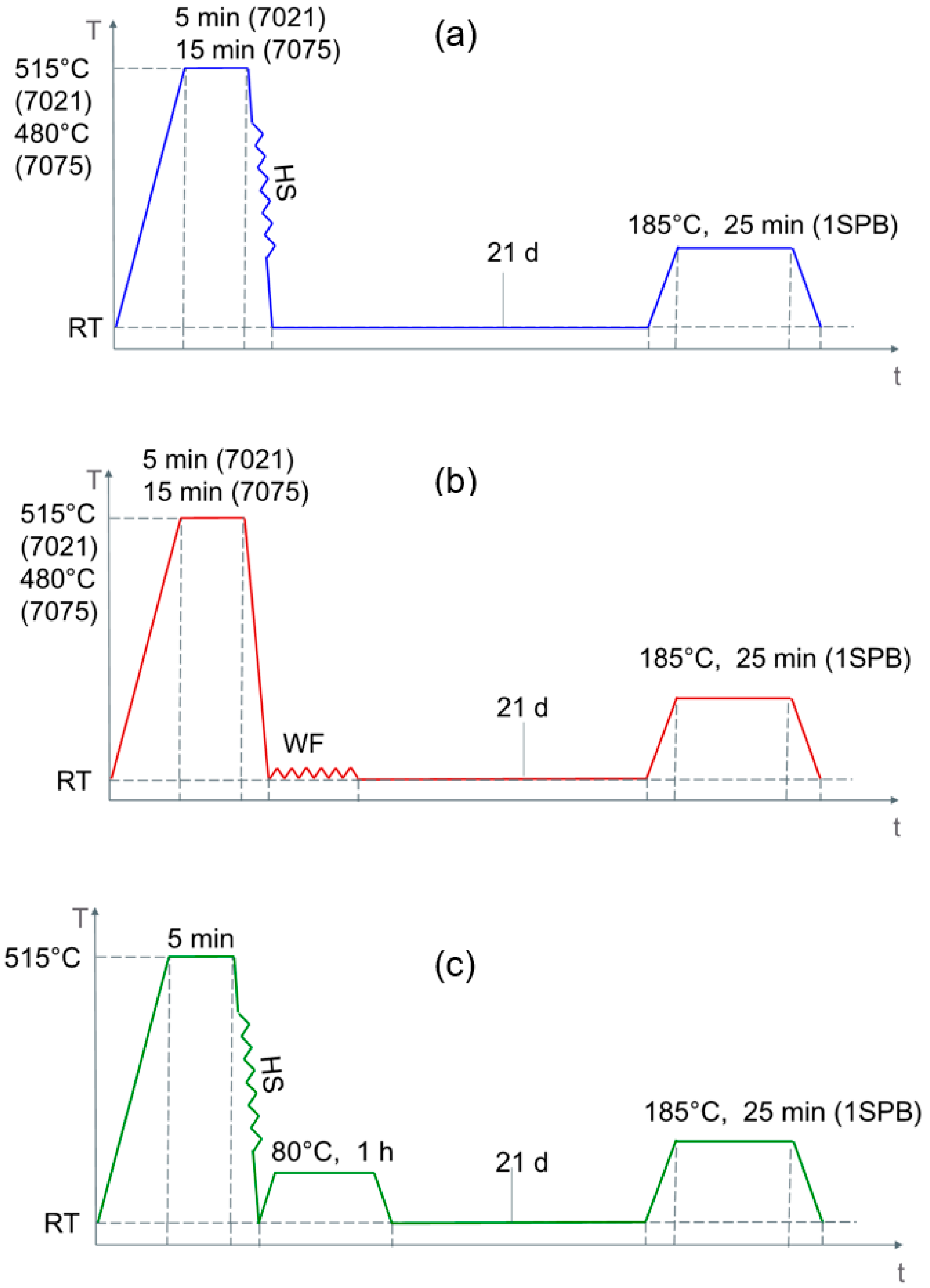
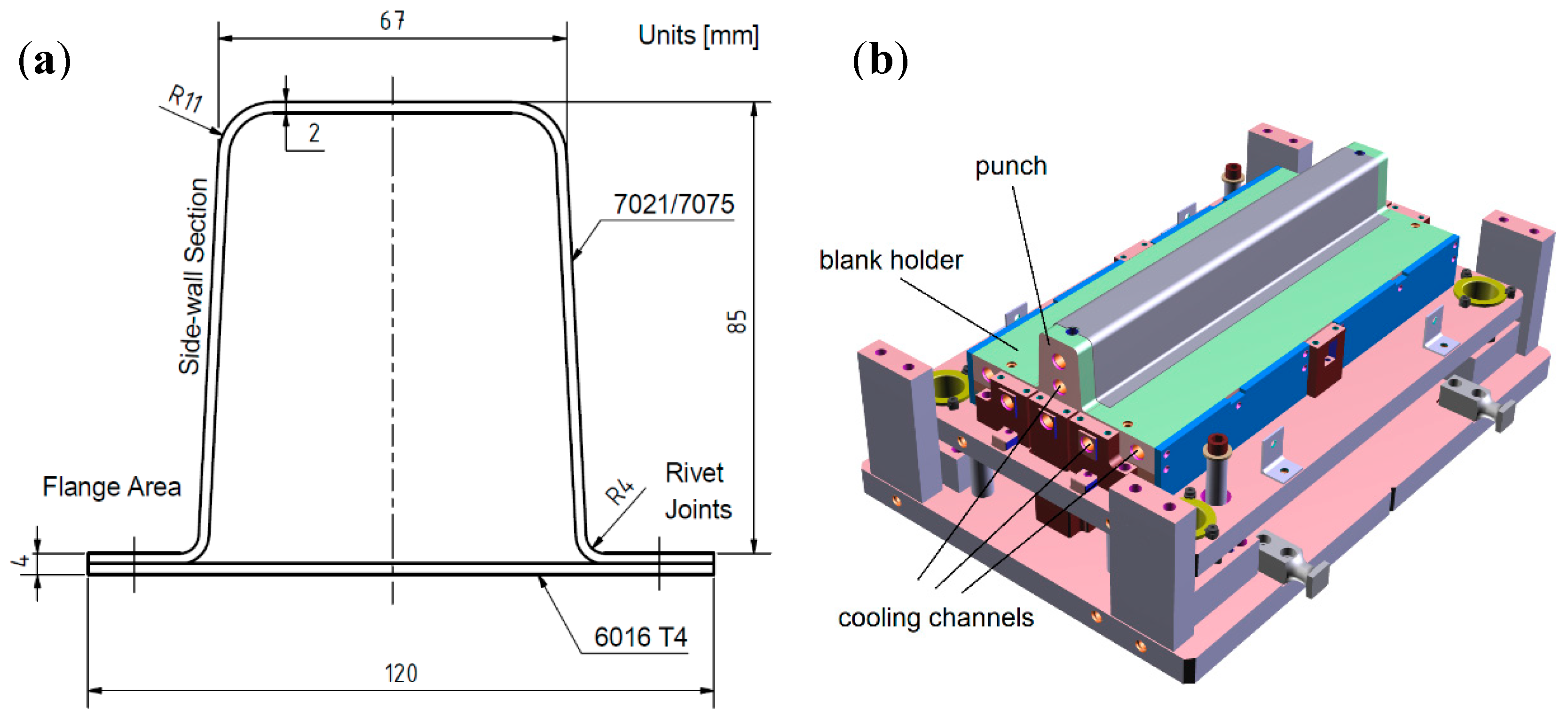
2.1. Materials and Process Chains

Modified EN AW-7021 T4 and EN AW-7075 T6 sheets with a thickness of 2 mm each were used. Their chemical composition is given in Table 1. Although the Zn and Mg contents of the modified EN AW-7021 slightly exceed the composition limit of a standard EN AW-7021 alloy, it is referred to as 7021 in the following. EN AW-7075 is referred to as 7075 in the following.
Figure 2 shows the temperature-time and forming sequences of the process chains investigated. For all process chains, the sheets were solution heat treated according to the annealing parameters identified by Milkereit et al. [6]: 515 °C/5 min for 7021; 480 °C/15 min for 7075. For hot stamping (HS, Figure 2a), the sheets were transferred as fast as possible from solution heat treatment to the press (within approximately 25 s). Quenching occurred during forming in the water-cooled die. For W-temper forming (WF, Figure 2b), the sheets were quenched by immersion in water, subsequently inserted into the dies and formed at room temperature within approximately 5 to 10 min after quenching. Hot-forming with subsequent stabilisation (HS-stab, Figure 2c) was only carried out for the 7021 alloy. The stabilisation heat treatment was conducted at 80 °C/1 h. Joining through self-pierce riveting was carried out within a time frame of up to 1 h after forming for the unstabilised process chains and 7 days after the additional heat treatment for the stabilised process chains (see below for details). Eventually, the parts were subjected to a one step paint bake heat treatment (1SPB) of 185 °C/25 min.
Top-hat profiles as depicted in Figure 3a were produced to characterise and compare the different process chains. Forming was carried out in a 1.6 MN single-acting hydraulic press with square blanks of 300 × 300 mm2 in size. The lower part of the corresponding tool with a part of maximum length (600 mm) can be seen in Figure 3b. The upper part (not shown) contains the die with a cavity to fit the punch from the lower part. The blank holder is situated at the lower part of the tool. During forming, the die moves downwards to draw the blank over the fixed punch. Die, punch and blank holder all contain cooling channels that were flushed with cold water during hot stamping. Before forming, the tool was lubricated using the white high-temperature paste Molyduval Moralub FSZ. The blanks were inserted manually into the tool with their rolling direction parallel to the longitudinal tool axis. They were positioned in the punch with the help of two centring marks on the blanks. Thereafter, the die moved into the punch for 85 mm with a speed of 50 mm/s. No blank holding force was applied to reduce springback after forming.
The cross section of formed top-hat profiles was closed through joining EN AW-6016 T4 cover plates to the flange area with C-SKR self-pierce rivets of hardness class H4 from Böhlhoff. The EN AW-6016-T4 sheet was in the upper position.

2.2. Formability

Tensile testing using a DIL 805A/D dilatometer (Bähr, Hüllhorst, Germany) was conducted to quantitatively evaluate forming characteristics of the different process chains. Specimens were taken from undeformed sheets in the as-delivered condition parallel to the rolling direction. They were heat treated directly within the dilatometer to replicate the desired forming state. The specimens were heated from room temperature to the respective test temperature within 6 s, held at this temperature for another 4 s and subsequently tested. This is a simplified approach to determine the properties of the undercooled states during quenching. Specimens had a reduced section width of 3 mm, a reduced section length of 10 mm and a gauge length of 8 mm. Tests have been carried out at two strain rates (0.01 s−1, 1 s−1) and measurements were conducted in triplicate.
On component level, a qualitative estimation of the different process chains’ formability could be gained from assessing dimensional accuracy and fracture behaviour of formed prototype parts.
The as-received material and formed side-wall section material were etched with Barker’s reagent to investigate how the forming operation has altered the original grain structure of the material.

2.3. Post-Forming Material Properties

The change of material properties along the process chains was assessed using hardness measurements, differential scanning calorimetry (DSC) and tensile testing. Hardness according to Brinell was measured three times using a test force of 62.5 kp (6.13 kN) and a sphere diameter of 2.5 mm (Instron, Darmstadt, Germany). DSC experiments were performed using a heat-flow based DSC 204 F1 device (Netzsch, Selb, Germany) with a heating rate of 10 K min−1. Tensile tests were carried out in triplicate as specified in Section 2.2. For all investigations, samples were taken from the side-wall section of formed parts. Tensile samples were cut parallel to the rolling direction.

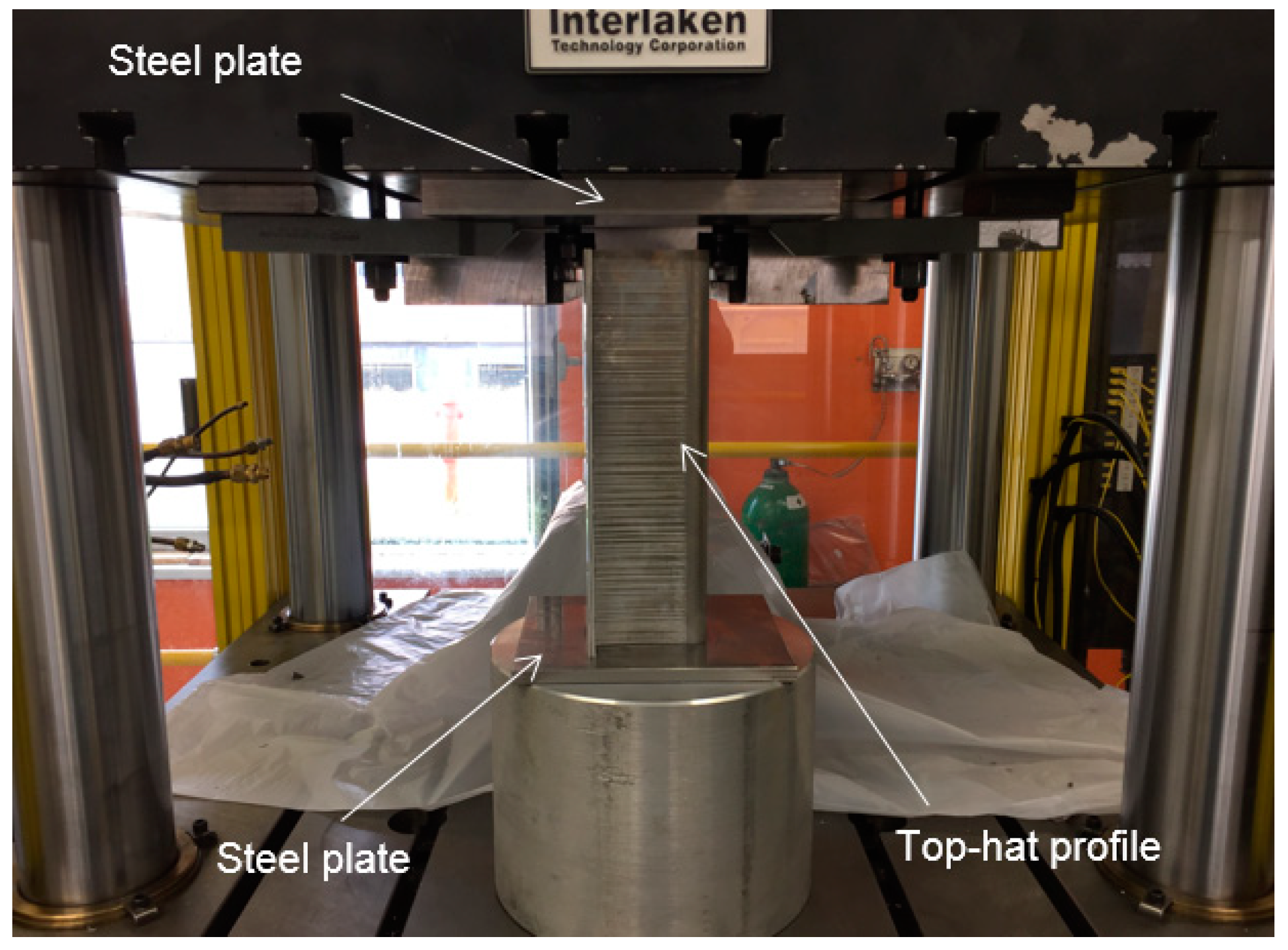
2.4. Energy Absorption Behaviour

Energy absorption behaviour was determined through quasi static compression testing on a servo-hydraulic ITC 255 press (Interlaken Technology Company, Interlaken, Switzerland) with a maximum punch force of 1000 kN. The formed and joined top-hat profiles were placed between two plane-parallel steel plates and compressed for 120 mm with a constant speed of 10 mm·s−1. All samples had an initial part length of 295 mm and were tested in the paint baked state. Figure 4 illustrates the test setup.

3. Results and Discussion
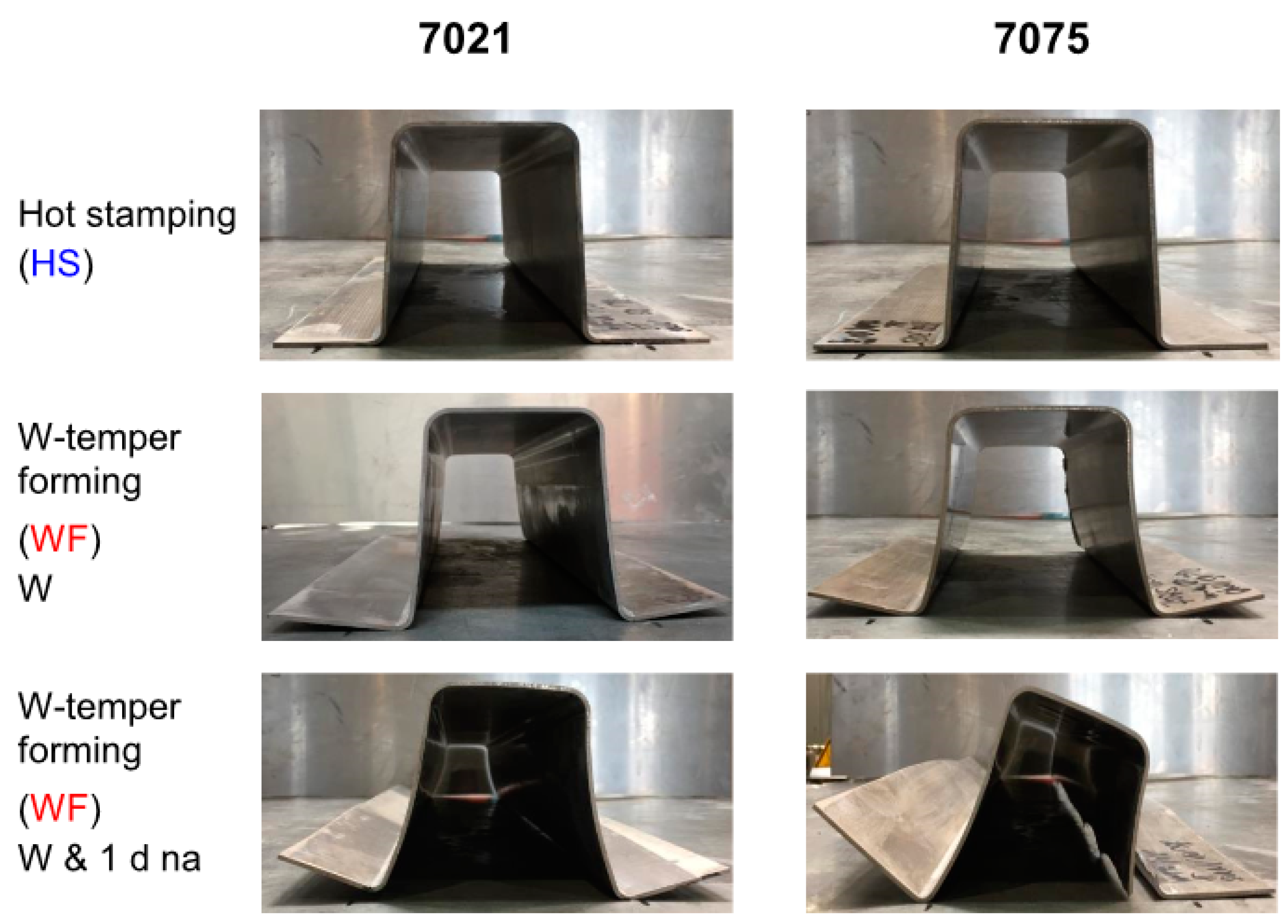
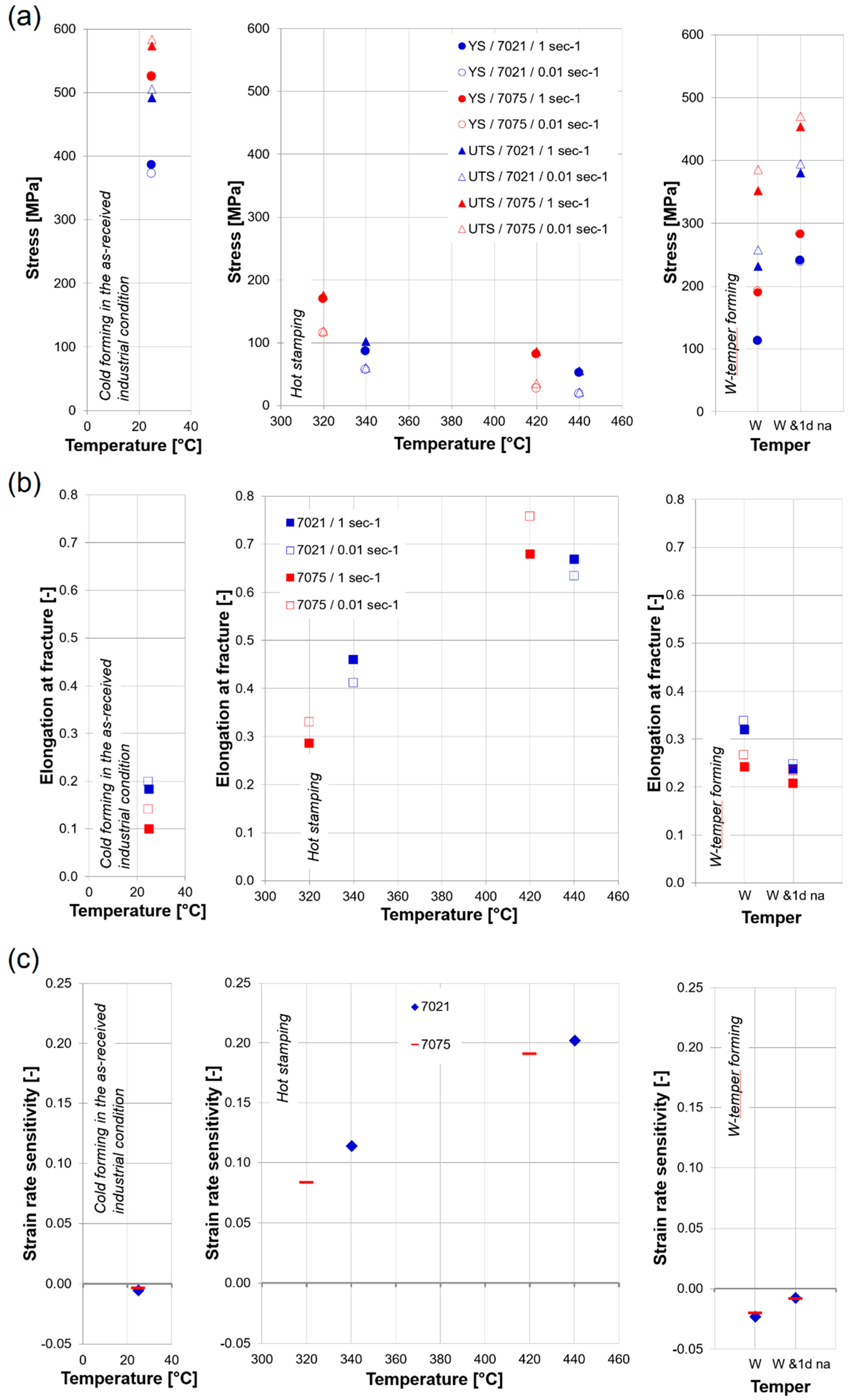
3.1. Formability

Yield strength (YS), ultimate tensile strength (UTS), elongation at fracture and strain rate sensitivity m = ln σ ln ε ˙ ε = ε u have been extracted from tensile testing data for the different forming states and are plotted in Figure 5. σ is the engineering stress at uniform elongation ε u and ε ˙ is the strain rate. An explanation on the mathematical formulation of strain rate sensitivity m is given in [13].
As can be seen in Figure 5a, yield strength and ultimate tensile strength both decrease with increasing temperature and decreasing strain rate. For temperatures above 300 °C, the difference between yield strength and ultimate tensile strength becomes small. The effect of strain hardening is thus particularly limited at higher deformation temperatures and dynamic softening mechanisms prevail. This is in line with the observations made by Kumar and Ross [14] on the hot tensile deformation behaviour of an Al-Zn-Mg sheet. For the W-temper (W), yield strength is 272 MPa (7021, 1 s−1), 260 MPa (7021, 0.01 s−1), 335 MPa (7075, 1 s−1) and 334 MPa (7021, 0.01 s−1) lower than in the as-delivered industrial condition (T6 for 7075 and T4 for 7021). Yield strength and ultimate tensile strength increase after 1 day of natural ageing (“W & 1 d na”). A significant difference in yield strength between the 1 s−1 and the 0.01 s−1 strain rate could not be observed for any of the alloys or tempers investigated. The ultimate tensile strength, however, is higher at the 0.01 s−1 strain rate for both alloys and tempers.
The effects of strain rate and temperature/temper on elongation at fracture are shown in Figure 5b. For the hot stamping states, elongation at fracture increases with rising temperature. It was found to be higher than 60% from 400 °C onwards for both alloys and strain rates. For the W state, elongation values of 7021 are about 10% higher than those of 7075. After 1 day of natural ageing, only minor differences exist between the two alloys. For almost all tempers and temperatures, elongation at fracture was found to increase with decreasing strain rates. However, for 7021 at 340 °C and 440 °C, the deformation capability is greater for the 1 s−1 strain rate. Zhou et al. [15] state that the effects of strain rate on elongation at fracture are governed by two opposite phenomena: On the one hand, increasing the strain rate might result in more tangled dislocations eventually blocking each other, decreasing ductility. On the other hand, especially when strain rates are low, microvoids and microcracks have more time to grow and coalescence. Therefore, material failure can also be more likely at lower strain rates.
Strain rate sensitivity m is an important parameter when it comes to choosing die speeds for a forming operation. As can be seen from Figure 5c, m is positive for elevated temperatures (i.e., above room temperature). In contrast, slightly negative m values were obtained for the as-delivered condition at room temperature and for the W-temper. Thermally-activated processes are believed to cause the positive strain rate sensitivity for the hot stamping states. Dynamic recovery and the dissolution of hardening precipitates take place more comprehensively during longer time spans. Since low strain rates increase deformation periods, they allow more time for dynamic recovery and, especially at higher temperatures, the coarsening or dissolution of hardening precipitates to happen [14]. According to Picu et al. [16] the slightly negative strain rate sensitivity of the W temper could be explained by solute atom clustering. Clustering close to dislocations tends to obstruct further dislocation movement and therefore an increase in stress can occur. At high strain rates, this mechanism is less pronounced and the dislocations can pass more easily.
Figure 6 shows how prototype parts produced through the different process chains perform with respect to dimensional accuracy and fracture behaviour. Using the hot stamping process chain, parts with linear side-wall section and no springback in the flange area could be formed with both, 7021 and 7075. W-temper forming yielded parts with springback in the flange area which was worse for 7075. After 1 day of natural ageing (“W & 1 d na”), it was still possible to form parts without fracture out of 7021 sheets at room temperature, although the dimensional accuracy was worse than achieved by W temper forming (W). In contrast, 7075 tore at the transition of side-wall section and flange area when room temperature forming was attempted after 1 day of natural ageing.
The results presented in this paper show good agreement with the investigations of Maeno et al. [17] on the springback behaviour of cold and hot stamped top-hat profiles from EN AW-2024. The authors also demonstrated that springback of the flange portion can significantly be reduced using the hot stamping approach compared to forming at room temperature.
At solution heat treatment temperatures, recrystallisation and grain growth can occur in Al wrought alloys [18]. However, we found that neither the hot stamping process nor the W-temper forming process has significantly changed the original grain structure of the material for any of the alloys used (Figure 7). This is in line with the findings of Harrison and Luckey [19] who also found that hot-stamping did not change the integrity of 7075 sheets when producing B-pillar shaped test parts.

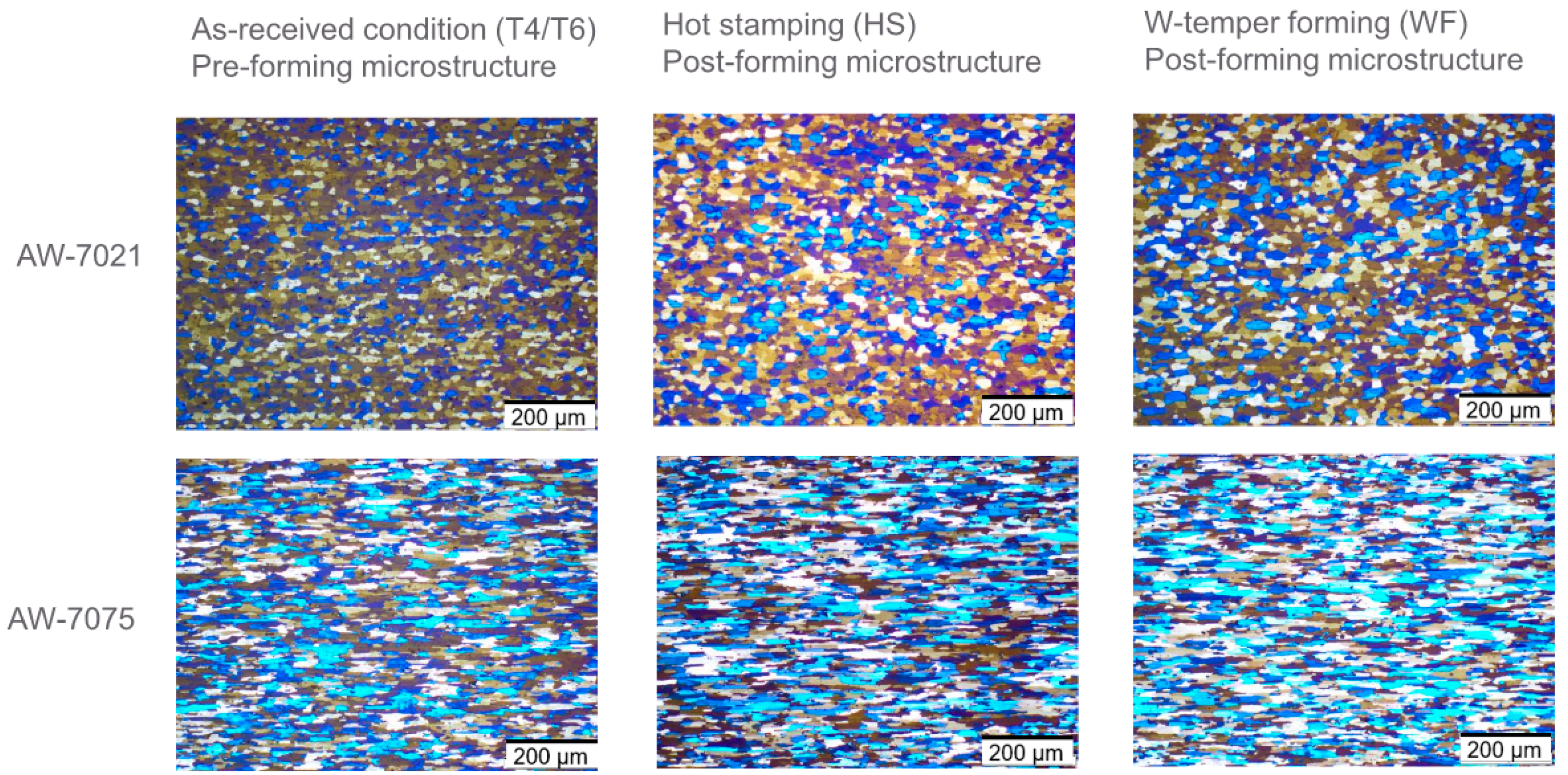
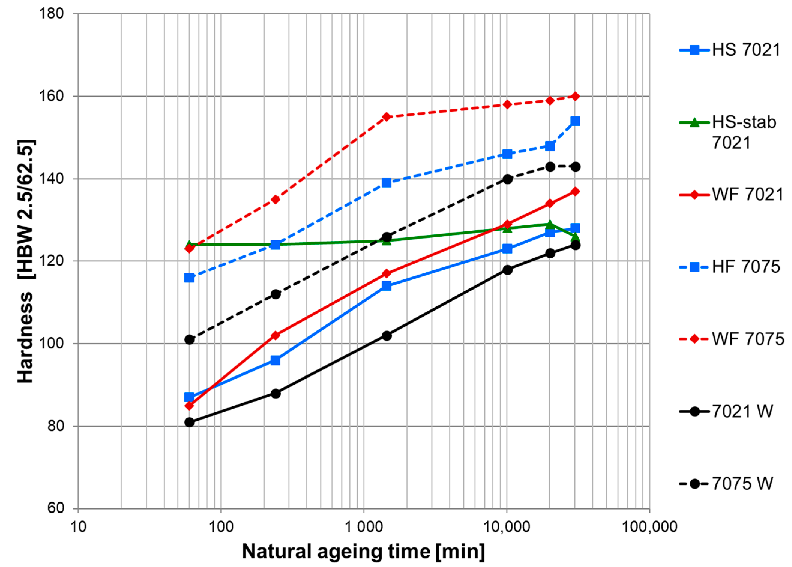
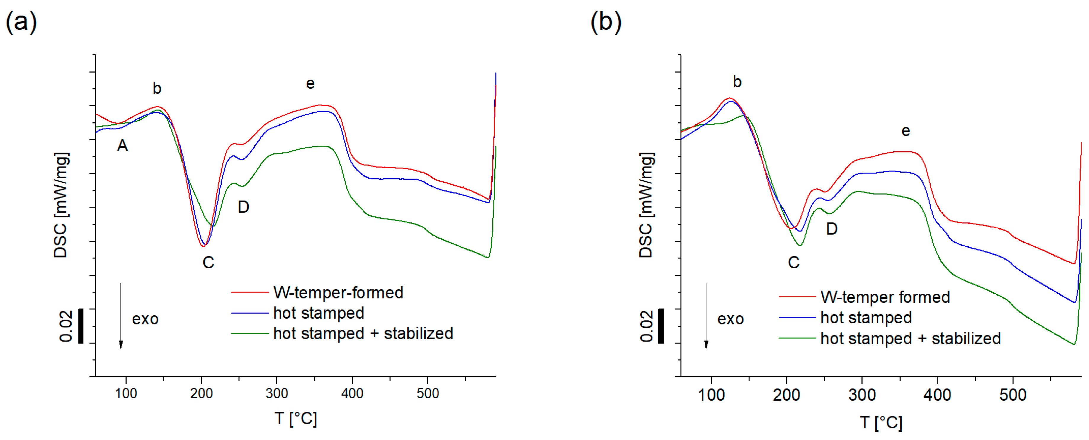
3.2. Post-Forming Material Properties

Figure 8 shows the hardness evolution due to natural ageing over the course of 21 days for the different process chains. Additional measurements of undeformed sheets in the W temper have been included in the diagram for reference. Forming increases the hardness of the sheets due to strain hardening and the HS and WF curves hence show a parallel shift to the undeformed W curves. Due to stronger strain hardening, the hardness of samples formed at room temperature (WF) is higher than the hardness of samples produced through hot forming (HS and HS-stab) during the entire 21 day period. A significant increase in hardness could be observed for the non-stabilised samples during the observation period. However, self-pierce riveting with reproducible undercut requires stable mechanical properties. Therefore, riveting is time-sensitive for the process chains without stabilisation. In contrast, the hardness of the stabilised process chain (HS-stab) remains approximately constant within an observation period of 21 days. This means that self-pierce riveting can be conducted with the same parameter set. Process standardisation and part logistics could thus be facilitated through the HS-stab process chain.
The natural ageing behaviour of the stabilised and unstabilised parts from 7021 was studied by DSC experiments (Figure 9). The results were interpreted in accordance with Österreicher et al. [10] using a simplified a precipitation sequence for EN-AW 7xxx alloys: α-supersaturated solid solution → GP-zones → η’ phase → η phase. The DSC curves of the WF, HS and HS-stab samples measured ~1 h and 21 days after forming are given in Figure 9a,b, respectively. The curves shown are representative curves out of two measurements with very good agreement. During heating of the WF sample ~1 h after forming (Figure 9a), an exothermic peak A appears at approximately 85 °C, most likely due to the formation of GP-zones. This peak is less pronounced for HS and missing for HS-stab, indicating that the formation of GP-zones has already occurred in these samples before the measurement. The GP-zones dissolve during the endothermic peak b at ~140 °C. On further heating, the η’ and η phases start to form as indicated by the exothermic peaks C and D, respectively.
The dissolution of all η’ and η phases takes places during the broad endothermic event e between approximately 290 and 370 °C. After 1 h of natural ageing (Figure 9a), peak C is much more pronounced for HS compared to HS-stab due to the higher supersaturation in HF. After 21 days of natural ageing (Figure 9b), the DSC signal of HS-stab has not changed significantly, indicating that the precipitate microstructure is stable over the storage period investigated. In contrast, for the unstabilised HS process chain, the natural ageing effect can clearly be observed: peak A is not visible anymore and peak C is less pronounced. One can conclude that the amount of GP-zones has risen, and the supersaturation of the matrix is lower. This is line with the increase in hardness displayed in Figure 8.
Figure 10 shows how forming, storage and artificial ageing alter the strength and ductility of the sheets. As expected, strength generally increases and elongation at fracture decreases after the paint bake treatment of naturally aged samples (1SPB) compared to only naturally aged samples (21 d). After 21 days of natural ageing, 7021 had considerably lower yield strength values than 7075 regardless of the process chain. Surprisingly, 7021 on average shows slightly higher yield strength values after subsequent 1SPB than 7075. For both alloys, samples taken from hot formed parts (HS 7021, HS 7075) showed comparable or even slightly higher yield strength values in the 1SPB state than samples taken from parts produced through W-temper forming (WF 7021, WF 7075). For the WF process chains, this might be due to more plastic strain induced during forming. Ostermann [20] (pp. 148–149) has reported that artificial ageing is accelerated, and ultimately lower strength values are achieved the more EN AW-7xxx series alloys have been strain hardened prior to tempering. Furthermore, elongation at fracture after 1SPB was higher for 7021 compared to 7075. Especially stabilised samples (HS-stab 7021) showed comparatively high elongation at fracture values. With respect to energy absorption behaviour in car crash situations, the high yield strength combined with good ductility of the HS-stab 7021 process chain is highly desirable.

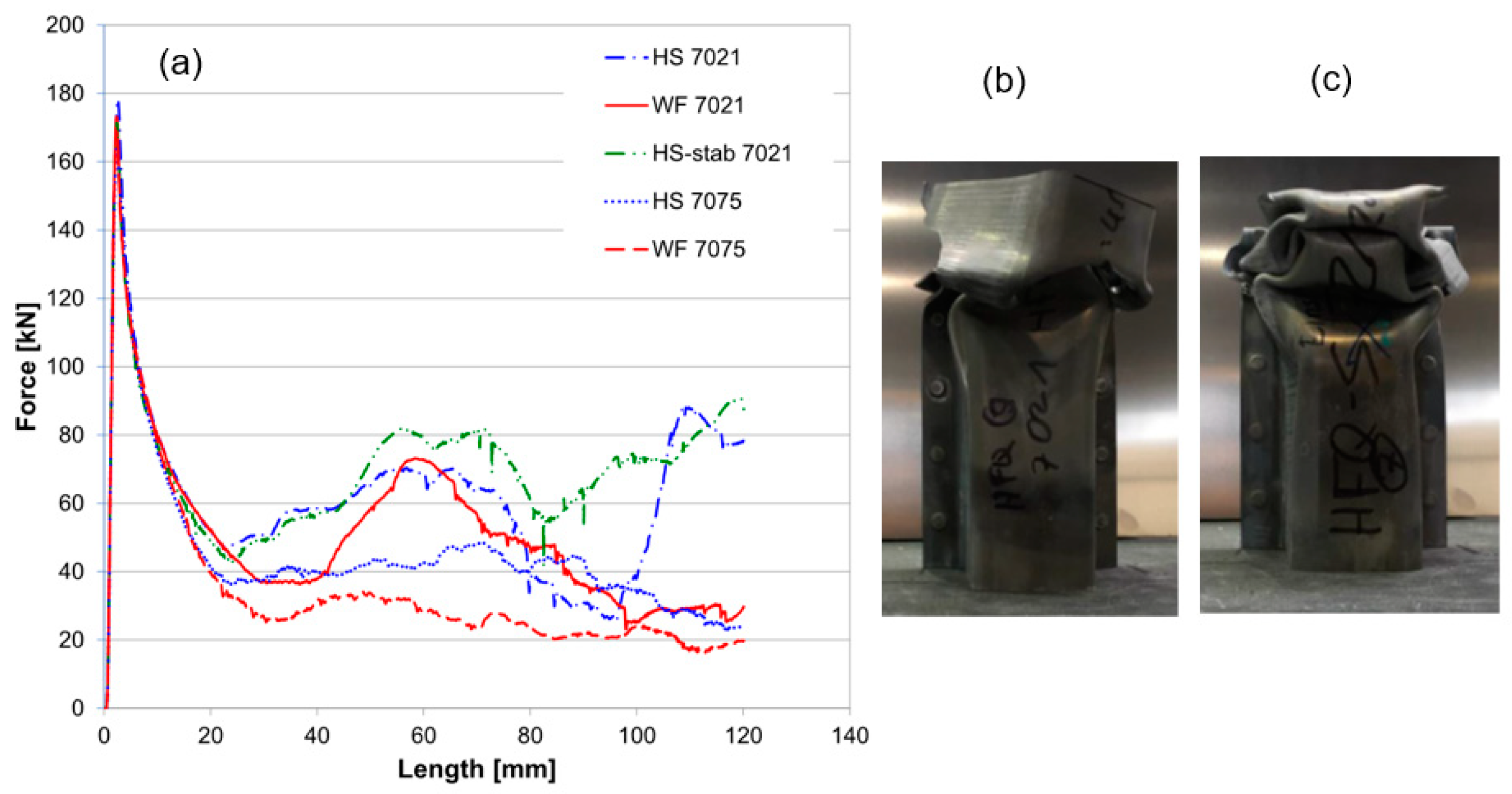
3.3. Energy Absorption Behaviour

Figure 11a shows the averaged curves from quasi-static compression testing of three representative samples. In all curves, an initial force peak can be observed indicating the start of plastic deformation. This trigger force is higher for the 7021 samples than for the 7075 samples which may be linked to the higher yield strength of 7021 after 1SPB. A second increase in force starts at approximately 25 mm for the HS-stab 7021 and HS 7021 curves, while force levels of WF 7021 curves start to rise again after approximately 45 mm. Parts made from 7075 do not show major increases in force after the first peak.
All 7021 process chains exhibit a second force peak at approximately 60 to 70 mm displacement. Parts produced through hot stamping (HS 7021, HS-stab 7021) show a final increase in force after having reached the second force peak, while force levels of WF 7021 samples continuously decrease thereafter. It should be noted that the energy absorption of the stabilised parts (HS-stab 7021) is higher than that of non-stabilised ones (HS 7021 and WF 7021). This is reflected by the better folding capability of stabilised parts compared to the other process chains as shown exemplarily for compressed HS-stab 7021 and HS 7021 top-hat profiles in Figure 11b,c. Plasticity of unstabilised top hat-profiles (HS 7021, WF 7021, HS 7075, WF 7075) was not high enough to initiate a periodical deformation pattern during quasi-static compression testing. In contrast, stabilised profiles (HS-stab 7021) were able to produce two entire folds and did not exhibit major cracks.
Several crashworthiness parameters such as specific energy absorption (SEA, Figure 12a) and crush force efficiency (CFE, Figure 12b) have been extracted from the force-length curves discussed above. The amount of energy absorbed (EA) corresponds to the area below the force-length curve and was determined through numerical integration. To ensure comparability for different geometries and test setups, it was divided through the structure’s initial mass m to obtain specific energy absorption SEA = EA m . Crush force efficiency CFE = MCF TF is defined as the ratio between the mean crush force (MCF) between 20 mm and 120 mm displacement and the initial trigger force (TF). High crush force efficiency ratios indicate that the structure is capable of absorbing adequate amounts of energy without evoking excessively high trigger forces. Such a behaviour is desired to reduce the occupants’ injury risk during a crash [21].
As can be seen in Figure 12, parts produced through the HS-stab 7021 process chain perform best in terms of both SEA and CFE. Profiles from the hot stamping process chain HS 7021 perform better in all categories than their counterparts from the W-temper forming process chain WF 7021. The same holds true for the 7075 alloy, although on a much lower level of crashworthiness. According to the test setup, all values shown in Figure 12 have been determined for a relative deformation of 0.4. Relative deformation is calculated as the quotient of punch displacement and initial sample length before compression testing.
A comparison of the results from this study with previous findings is difficult. First, little has been published on the energy absorption behaviour of EN AW-7xxx structures. Secondly, the test setup of previous work greatly varies with respect to part geometry, joining method, crush length and test speed. Still, our results seem to be consistent with the findings of two previous studies: Estrada et al. [22] have performed finite element simulations to analyse the effect of mechanical discontinuities on the crashworthiness of EN-AW 7108 T6 aluminium extrusions under dynamic loading. The extrusions were 400 mm in length, the dimension of the rectangular cross-section was 68 × 95 mm2 and sheet thickness was 2.5 mm. A striker mass of 500 kg impacted the parts with an initial velocity of 10 m/s at one end, the other end was placed in a rigid support. According to their models, the extrusions can absorb about 14.28 J/g at a relative deformation of about 0.4. Size and position of the mechanical discontinuities have already been optimised at that stage. Kirov [23] has conducted quasi-static compression testing with structurally glued top-hat profiles from EN AW-5083 sheets. The profiles had a similar cross-section to the ones investigated within this work but were 400 mm in length. They were compressed for 200 mm at a constant speed of 10 mm/s, thus final relative deformation was at about 0.5. The profiles were able to produce four entire folds. However, their cover plates were not included in the folding pattern but sheared off. When reaching a relative deformation of 0.5, the parts had absorbed about 6.2 kJ. Assuming a largely linear energy-deformation curve, this would correspond to 4.96 kJ at a relative deformation of 0.4. In comparison, the absolute/specific energy absorption in this study on average ranged from 4.15 kJ or 6.21 J/g (WF 7075) to 8.39 kJ or 12.82 J/g (HS-stab 7021) at a relative deformation of 0.4.

4. Conclusions

This work has characterised process chains for the production of automotive structural parts from EN AW-7075 and modified EN AW-7021 aluminium sheets. It highlights the importance of considering the entire process chain for achieving good material properties with respect to both processability and crashworthiness. The main conclusions are:
  • For the materials tested, hot stamping is better suited to obtain failure-free parts with good dimensional accuracy than W-temper forming. For both alloys, yield strength is considerably lower and elongation at fracture is increased at temperatures above 300 °C compared to the W temper.
  • Compared to parts produced by W-temper forming, parts produced by hot stamping showed similar yield strength and significantly better elongation at fracture (7021: 2% higher, 7075: 4% higher) after a paint-bake heat treatment. Also, parts made from the modified EN AW-7021 outperformed parts from EN AW-7075 regarding tensile testing and crashworthiness results.
  • For the modified EN AW-7021, an additional low temperature pre-ageing heat treatment (80 °C/1 h) after hot stamping yielded a state that did not vary significantly in hardness during an observation period of three weeks. This can be favourable for subsequent operations such as self-pierce riveting. Furthermore, stabilised parts showed better crashworthiness parameters such as specific energy absorption (15% higher) and crush force efficiency (10% higher).
The results show that the process chain hot stamping with subsequent stabilisation of EN AW-7021 is most promising with respect to formability, post forming material properties, and energy absorption behaviour. Our findings may justify the additional effort of a stabilisation heat treatment and promote an increased use of high-strength EN AW-7xxx alloys for structural car parts in the future.

Author Contributions

P.A.S., J.A.Ö. and G.K. performed the experiments and analysed the data. P.A.S. and J.A.Ö. wrote the paper. C.S., O.K. and E.M. assisted in experimental design, analysing the results, and editing the manuscript. All authors checked the manuscript and have given their consent to the latest version.

Funding

This work was funded by the Austrian Research Promotion Agency (FFG), the Federal Ministry for Transport, Innovation and Technology (BMVIT) and the State of Upper Austria in the framework of the COMET projects AMALFI and AMOREE (grant numbers 872641 and 843537).

Acknowledgments

The authors would like to thank Florian Grabner, Josef Domitner and the technical staff of LKR Ranshofen GmbH for their competent cooperation and assistance during the completion of this research. The authors would further like to express their gratitude to Magna Steyr Fahrzeugtechnik AG & Co KG for supporting this research and the permission to publish this article, as well as Aleris Aluminum Duffel BVBA for providing some of the material used.

Conflicts of Interest

Ermal Mukeli is an employee of Magna Steyr Fahrzeugtechnik AG & Co KG, a company that may be affected by the findings of this research. The other authors have no conflicts of interest to declare.

References

  1. Hirsch, J. Aluminium in Innovative Light-Weight Car Design. Mater. Trans. 2011, 52, 818–824. [Google Scholar] [CrossRef] [Green Version]
  2. Berger, L.; Lesemann, M.; Sahr, C.; Hart, S.; Taylor, R. SuperLIGHT-CAR—The Multi-Material Car Body. In Proceedings of the 7th European LS-DYNA Conference, Salzburg, Austria, 14–15 May 2009. [Google Scholar]
  3. Grohmann, C. Forming of AMAG 7xxx Series Aluminium Sheet Alloys. In New Developments in Sheet Metal Forming, Stuttgart. 2016. Available online: https://www.researchgate.net/publication/303699665 (accessed on 5 March 2019).
  4. Schaeffler, D.J. Getting to know more about the metal you are forming. 2016. Available online: https://www.thefabricator.com/article/metalsmaterials/getting-to-know-more-about-the-metal-you-are-forming (accessed on 9 January 2019).
  5. Kumar, M.; Kirov, G.; Grabner, F.; Mukeli, E. Sheet Forming Processes for AW-7xxx Alloys: Relevant Process Parameters. Mater. Sci. Forum 2016, 879, 1036–1042. [Google Scholar] [CrossRef]
  6. Milkereit, B.; Österreich, M.; Schuster, P.; Kirov, G.; Mukeli, E.; Kessler, O. Dissolution and Precipitation Behavior for Hot Forming of 7021 and 7075 Aluminum Alloys. Metals 2018, 8, 531. [Google Scholar] [CrossRef]
  7. Mendiguren, J.; Saenz de Argandona, E.; Galdos, L. Hot stamping of AA7075 aluminum sheets. In IOP Conference Series: Materials Science and Engineering; Linz, Austria, 2016. [Google Scholar] [CrossRef]
  8. Sáenz de Argandoña, E.; Galdos, L.; Ortubay, R.; Mendiguren, J.; Agirretexe, X. Room temperature forming of AA7075 aluminum alloys: W-temper process. Key Eng. Mater. 2015, 651–653, 199–204. [Google Scholar]
  9. Harrison, N.R.; Nadeau, F.; Brüx, U.; Luckey, S.G. In Proceedings of the 16th International Aluminium Alloys Conference (ICAA16), Montreal, 2018. Available online: http://www.icaa-conference.net/ICAA16/Papers/New%20Directions/401839%20Harrison_final.pdf (accessed on 5 March 2019).
  10. Österreicher, J.A.; Kirov, G.; Gerstl, S.S.A.; Mukeli, E.; Grabner, F.; Kumar, M. Stabilization of 7xxx aluminium alloys. J. Alloys Compd. 2018, 740, 167–173. [Google Scholar] [CrossRef]
  11. Lee, Y.S.; Koh, D.H.; Kim, H.W.; Ahn, Y.S. Improved bake-hardening response of Al-Zn-Mg-Cu alloy through preaging treatment. Scr. Mater. 2018, 147, 45–49. [Google Scholar] [CrossRef]
  12. Omer, K.; Abolhasani, A.; Kim, S.; Nikdejad, T.; Butcher, C.; Wells, M.; Esmaeili, S.; Worswick, M. Process parameters for hot stamping of AA7075 and D-7xxx to achieve high performance aged products. J. Mater. Process. Technol. 2018, 257, 170–179. [Google Scholar] [CrossRef]
  13. Ghosh, A.K. On the measurement of strain-rate sensitivity for deformation mechanism in conventional and ultra-fine grain alloys. Mater. Sci. Eng. A 2007, 463, 36–40. [Google Scholar] [CrossRef]
  14. Kumar, M.; Ross, N. Investigations on the hot stamping of AW-7921-T4 alloy sheet. Adv. Mater. Sci. Eng. 2017, 2017, 7679219. [Google Scholar] [CrossRef]
  15. Zhou, M.; Lin, Y.C.; Deng, J.; Jiang, Y.Q. Hot tensile deformation behaviors and constitutive model of an Al–Zn–Mg–Cu alloy. Mater. Des. 2014, 59, 141–150. [Google Scholar] [CrossRef]
  16. Picu, R.C. A mechanism for the negative strain-rate sensitivity of dilute solid solutions. Acta Mater. 2004, 52, 3447–3458. [Google Scholar] [CrossRef]
  17. Maeno, T.; Mori, K.; Yachi, R. Hot stamping of high-strength aluminium alloy aircraft parts using quick heating. Manuf. Technol. 2017, 66, 269–272. [Google Scholar] [CrossRef]
  18. Rometsch, P.; Zhang, Y.; Knight, S. Heat treatment of 7xxx series aluminium alloys—Some recent developments. Trans. Nonferrous Met. Soc. China 2014, 24, 2003–2017. [Google Scholar] [CrossRef]
  19. Harrison, N.R.; Luckey, S.G. Hot Stamping of a B-Pillar Outer from High Strength Aluminium Sheet AA7075. SAE Int. J. Mater. Manuf. 2014, 7, 567–573. [Google Scholar] [CrossRef]
  20. Ostermann, F. Anwendungstechnologie Aluminium, 3rd ed.; Springer Vieweg: Meckenheim, Germany, 2014; pp. 88–92. [Google Scholar]
  21. Hussein, R.D.; Ruan, D.; Lu, G. Cutting and crushing of square aluminium/CFRP tubes. Compos. Struct. 2017, 171, 403–418. [Google Scholar] [CrossRef]
  22. Estrada, Q.; Szwedowicz, D.; Silva-Aceves, J.; Majewski, T.; Vergara-Vazquez, J.; Rodriguez-Mendez, A. Crashworthiness behavior of aluminum profiles with holes considering damage criteria and damage evolution. Int. J. Mech. Sci. 2017, 131–132, 776–791. [Google Scholar] [CrossRef]
  23. Kirov, G. Numerische Betrachtungsmethoden für Strukturell Geklebte Bauteile. Master’s Thesis, FH Oberösterreich, Wels, Austria, 2013. [Google Scholar]
Figure 1. Specific tensile strength plotted against elongation at fracture for different aluminium wrought (EN AW) alloy series, conventional steels, and advanced high-strength steels (AHSS). Own illustration based on [3,4].
Metals 09 00305 g001
Figure 2. Temperature-time process sequence for (a) hot stamping (HS), (b) W-temper forming (WF), (c) hot stamping with subsequent stabilisation (HS-stab).
Metals 09 00305 g002
Figure 3. (a) Cross section of produced top-hat profiles and (b) lower part of the corresponding deep-drawing tool.
Metals 09 00305 g003
Figure 4. Test setup used for quasi-static compression testing.
Metals 09 00305 g004
Figure 5. (a) Yield strength (YS) and ultimate tensile strength (UTS), (b) elongation at fracture and (c) strain rate sensitivity of 7021 and 7075 at different temperatures/tempers and strain rates.
Metals 09 00305 g005
Figure 6. Dimensional accuracy and fracture behaviour of formed top-hat profiles.
Metals 09 00305 g006
Figure 7. Pre- and post-forming microstructure for the HF and WF forming process chains.
Metals 09 00305 g007
Figure 8. Natural ageing behaviour of the alloys processed by different process chains.
Metals 09 00305 g008
Figure 9. DSC curves of HS 7021, WF 7021 and HS-stab 7021 measured (a) ~1 h and (b) 21 days after forming.
Metals 09 00305 g009
Figure 10. (a) Yield strength and (b) elongation at fracture after 21 days of natural ageing (21 d) and after 21 days of natural ageing and subsequent 1 step paint baking (1SPB). The bars indicate standard deviation from 3 measurements.
Metals 09 00305 g010
Figure 11. (a) Force-length curves from quasi-static compression testing and compressed (b) HS 7021 and (c) HS-stab 7021 top-hat profiles.
Metals 09 00305 g011
Figure 12. (a) Specific energy absorption and (b) crush force efficiency extracted from force-length curves recorded through quasi-static compression testing. The bars indicate standard deviation from 3 measurements.
Metals 09 00305 g012
Table 1. Chemical composition of the sheets in percent by weight (wt. %).
AlloysAlSiFeCuMnMgZnCrTiZrOthers
AW 7075-T6rest0.190.111.500.042.646.060.180.040.02max. 0.03
AW 7021-T4restmax. 0.25max. 0.40max. 0.16max. 0.101.60–2.106.00–6.80max. 0.05max. 0.1max. 0.18 max. 0.15

