Mechanical Properties of Tool Steels with High Wear Resistance via Directed Energy Deposition

1
Department of Mechanical Engineering, Chonnam National Univ., 77 Yongbong-ro, Buk-gu, Gwangju 500-757, Korea
2
Smart Manufacturing Process Technology Center, KITECH, Wolchul-dong, Buk-gu, Gwangju 500-460, Korea
3
Division of Mechanical Engineering, Korea Maritime and Ocean University, 727 Taejong-ro, Yeongdo-Gu, Busan 49112, Korea
*
Author to whom correspondence should be addressed.
Metals 2019, 9(3), 282; https://doi.org/10.3390/met9030282
Submission received: 19 December 2018
/
Revised: 14 January 2019
/
Accepted: 14 January 2019
/
Published: 1 March 2019
(This article belongs to the Special Issue Additive Layer Manufacturing using Metal Deposition)
Abstract
:This study focused on the mechanical and metallurgical characteristics of high-wear-resistance steel (HWS) deposited using directed energy deposition (DED) for metal substrate hardfacing or repairing. As post-deposition heat treatment changes the metallurgical characteristics of deposits, the effect of post-deposition heat treatment on the mechanical properties was investigated via microstructure observation and by conducting hardness, wear, and impact tests. The obtained micro-images showed that the deposited HWS layers exhibit cellular and columnar dendrites, and the microstructure of heat-treated HWS (HT-HWS) transformed its phase during quenching and tempering. The hardness and wear resistance of the HT-HWS deposits were higher than those of the HWS deposited specimen, whereas the latter exhibited a higher fracture toughness. The matrix microstructure and carbide characteristics, which are characterized by the chemical composition of the materials, significantly influenced the mechanical properties.
1. Introduction
The directed energy deposition (DED) process can be used for hard facing of the die surface and repair of products with a short lifetime to give a superior fine microstructure and strong fusion between the base materials and the deposited layer [1]. The mechanical properties of the deposited layer obtained using the DED technique depend on the materials to be melted [2]. Therefore, for hardfacing and repairing, it is necessary to confirm the required mechanical and metallurgical characteristics. This topic is closely related to general strengthening mechanisms of materials. Moreover, the chemical composition of the material is an important factor related to mechanical properties.
Conventionally, AISI D2 (American Iron and Steel Institute) tool steels hardened by heat treatment are widely used for fabricating cold-press dies and tool steels because they exhibit appropriate wear resistance, high toughness, and good machinability. However, in the forming and shearing of advanced high strength steel (AHSS) sheet metals, which have a high tensile strength, the conventional die steel (D2) is limited because of premature wear and fracture.
In attempts to rectify this problem, various researchers have attempted to implement hardfacing technology using laser melting technology, in which high-performance powder materials are cladded or deposited onto the surface of the target material. With the purpose of improving the tool life, many studies have reported an improvement of the wear resistance of the target material resulting from the deposition of a high-performance thin layer on it. Telasang et al. [3] performed a parameter study of the H13 powder laser cladding, and a subsequent study reported that post-tempering increased the fraction of carbides in microstructures, and reduced the residual stress [4]. Wang et al. [5] improved the wear resistance of D2 tool steel using CPM powders and M4 powder, which formed carbides in the microstructure during the laser cladding process. They also investigated the post heat-treatment effect of each of the powders. Shim et al. [6] introduced a substrate preheating process that removes delamination in the M4 deposition, and investigated the M4 characteristics deposited using preheated substrates. They subsequently reported that the mechanical properties varied depending on the post-heat treatment [7]. As a result, the mechanical properties were improved compared to the heat-treated D2. The conventional post-heat treatment method is sufficiently applicable not only for welding, but also for improving the mechanical and metallurgical characteristics of the laser melting deposition. In the case of a large amount of retained austenite in the microstructure of the laser melting layer, it is possible to improve the mechanical properties through phase transfer to martensite or lath structure through post-heat treatment [5].
The studies cited above confirm that hardfacing techniques can effectively improve mechanical properties. Most studies employed high-carbon steel powders to maximize the hardness and wear resistance. However, for laser melting with high-carbon steel, when both the deposition area and the deposition height increase, fine cracks and delamination are possible between the substrate and the deposited layer during or after the deposition process. The main cause of these defects is the thermal stress caused by the melting and solidification of the metal by the high power laser, which is a result of the repetitive cycle and thermal expansion coefficient with a high carbon content [8]. Therefore, a material containing a hardening element (e.g., Mo, V, and W) with a low carbon content can be used as the hardfacing material to minimize the thermal stress. High-wear-resistance steel (HWS) is expected to be suitable for laser melting. The Rovalma S.A. company developed HWS steel, which is a new alloy tool steel with a high wear resistance and exceptionally high toughness. Leunda et al. [9] employed a laser cladding technique to repair a die using HWS powder and compared the hardness and microstructure. In addition, they increased the hardness by laser beam tempering. However, there is no report on the wear resistance or toughness, which is very important for evaluating die performances [10].
This study focused on laser melting deposition with HWS powders and the effects of post-heat treatment on the metallurgical and mechanical characteristics of the deposited HWS layer. The HWS powder was deposited on a D2 surface, and the mechanical properties evaluated depending on the post-heat treatment. The properties were then compared with those of the deposited M4 layer. A ball-on-disc test was also conducted to evaluate the wear resistance and a Charpy impact test for the fracture toughness.
2. Materials and Methods
2.1. Materials
For the experiment, the substrate used was AISI D2 bulk steel, and AISI M4 (supplied by Carpenter Co., Philadelphia, PA, USA) and HWS (supplied by Rovalma S.A., Barcelona, Spain) powders were used as the depositing materials. The substrate was machined to dimensions of 50 mm × 100 mm × 10 mm. As shown in Figure 1, the powders of M4 and HWS comprise spherical particles with diameters in the range of 50–150 μm. The powders are manufactured using a gas atomizer. Table 1 lists the chemical compositions of each material. The M4 material has a high carbon content and high W, Mo, Cr, and V contents. On the other hand, HWS has a higher Cr content than M4.
2.2. Directed Energy Deposition (DED)
Figure 2 shows a schematic diagram of the DED process for the molten pool, in which the substrate and powder are melted. The equipment consists of a 4 kW CO2 laser oscillator, a powder hopper, and a gas feeder (MX-3, INSTECH Co., Daejeon, Korea). These pieces of equipment are controlled by the main controller for the laser tool path, gas supply, laser power, etc. In this study, the laser power during the deposition was 800–900 W, and the argon gas was used in the coaxial and powder feeding. The beam spot diameter was 1.0 mm with a top-hat intensity distribution; thus, overlapping tracks were applied with a pitch of 0.5 mm. The slicing height was set to 0.5 mm, which was based on the single-layer height for a given depositing condition (as listed in Table 2).
In addition, a high-frequency induction heating system was employed for the substrate heating. According to a previous study on M4 deposition [11], to reduce the thermal stresses and prevent the formation of cracks, the substrate should be preheated during deposition. However, the HWS employed in this study could be deposited at room temperature without pre-heating. Therefore, pre-heating was only used for the M4 deposition. Except for the preheating, the other process conditions were set the same. Table 2 lists the values of the processing parameters.
2.3. Experimental Procedure
To investigate the effects of post-heat treatment on the deposited HWS, the heat treatment was performed by quenching and tempering. For the quenching, the specimen was isothermal at 1323 K for 120 min in a nitrogen purging chamber after vacuum, and gas-quenched at 2 bar. The tempering was conducted three times at 793 K for 120 min.
To observe the microstructure of the deposited layer, electrolytic polishing was performed using Lectropol-5 (Struers Corp., Cleveland, UT, USA) for each of the deposited samples. Electrolytic polishing was carried out with the following values: Voltage: 35 V, time: 25 s, and flow rate: 9 L/min using electrolyte (A3 solution, perchloric acid: butoxyethanol: methanol, ratio of 1:6:4) at a current of 0.80 A.
The microstructure was observed using a field emission scanning electron microscope (FESEM, JEOL Ltd., 7100 f, Tokyo, Japan). The carbides were analyzed using energy dispersive spectrum analysis (EDS) on the SEM image. In addition, the X-ray diffraction (XRD, KURARAY Ltd., Tokyo, Japan) was analyzed for the identification of phases volume fraction. The quantitative XRD analysis was performed using the RIR (reference intensity ratio), which was provided by PDXL dedicated software (Rigaku Corp., Tokyo, Japan). The XRD was performed using Cu Kα radiation generated at 50 kV and 40 mA; the diffraction angle was varied between 20° and 120° at a scan rate of 5°/min.
The hardness test, the wear test, and the impact test were carried out to evaluate the mechanical properties of the HWS deposited layer, and the method is described in more detail in a previous study [12]; hardness was performed by micro-hardness (Akashi Co., Tokyo, Japan). The hardness at each position was obtained by calculating the area of the indentation mark produced by a load of 980.7 mN for 10 s using the penetrator.
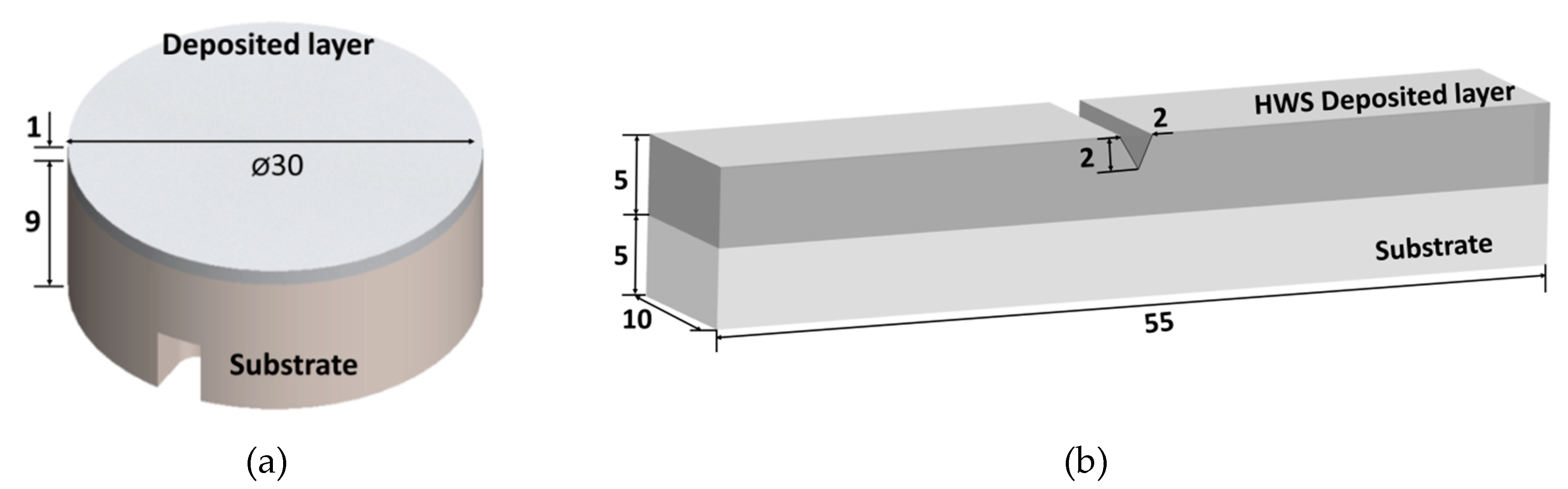
The wear specimens were prepared with a 1.0-mm-thick layer deposited onto a cylindrical substrate, as shown in Figure 3a. A ball-on-disk wear tester (R&B Inc., Daejeon, Korea) was used, and the cemented carbide ball (Ø12.7 mm) was set to be rotated on the top surface of the specimen for 10 min under a load of 147.1 N (15 kgf) and at a ball speed of 100 rpm.
To evaluate the toughness, which is the resistance against fracture, the Charpy impact test was performed. The specimen for the impact test was prepared with a 5 mm height of the deposited layer. A 2-mm-deep V-notch was formed in the specimen, in keeping with the ASTM E23 standard, as shown in Figure 3b. The impact test was performed at room temperature using a Charpy impact machine; the impact energy, impact velocity, and impact angle were set to 50 J, 3.8 m/s, and 150°, respectively. The impact absorption energy was calculated after the impact test, and the morphology of the fracture surface was examined using FE-SEM.
3. Results and Discussion
3.1. X-ray Diffraction
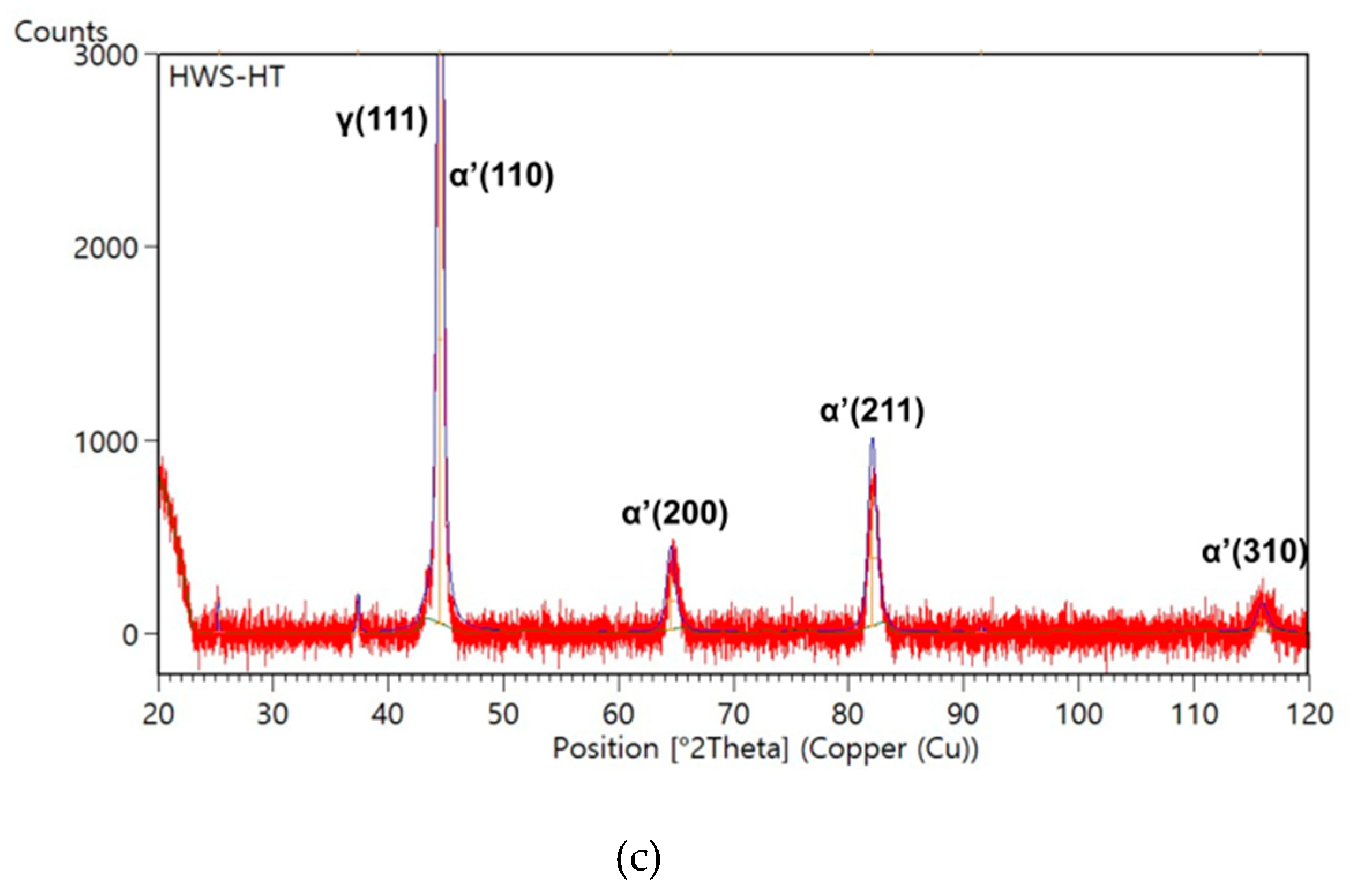
To confirm the phase, carbides, and crystal structure formed in the deposited layers, XRD analysis was performed such that the cross section (5 mm × 5 mm) of only the deposited layer was irradiated with x-ray (Figure 4). Figure 5a–c shows the X-ray diffraction patterns of M4, HWS, and HT-HWS, respectively. The results show different XRD patterns depending on the chemical compositions and post-deposition heat treatment, with gamma (γ, austenite, ICDD number 03-065-9094) and alpha prime peaks (α’, martensite, ICDD number 03-065-4899) observed in common. The M4 spectrum is characterized by gamma, alpha prime, and M6C peaks (Figure 5a). The quantitative analysis results show that the gamma content is 22%, and the alpha prime is 78%. Thus, the matrix structure in M4 was identified as austenite and martensite, and M6C carbides shown at 38° and 40° were identified from another study [5]. Nevertheless, MC carbide and M23C carbide precipitate in M4; however, they could not be identified in the XRD analysis in this study. In the HWS spectrum, only gamma and alpha prime are patterned (Figure 5b). The martensite and austenite structures are formed by melting and rapid cooling. The fraction of carbide observed in the microstructure is expected to be lower. The gamma and alpha prime contents are 61% and 39%, respectively. HWS contains a higher austenite fraction than M4, in accordance with their chemical compositions: HWS has both a lower C (i.e., austenite-stabilizing element) content and higher Si and Cr (ferrite-stabilizing) contents than M4. The HT-HWS exhibits a phase transformation in the microstructure, and the XRD pattern is different from the HWS because of the post-heat treatment, which reduced the austenite fraction and increased the martensite fraction in the matrix (Figure 5c). When quenched from an austenite state to room temperature with rapid cooling, there is not enough time for the carbon to diffuse. As a result, carbon remains in the solid solution state in α iron, and the retained austenite in the deposited layer is transformed to martensite by quenching.
3.2. Microstructure
Elemental composition analysis (based on microstructure observation) and EDS were conducted for the metallurgical characterization in conjunction with the XRD analysis. Regarding the microstructures of the deposited M4, HWS, and HT-HWS, two regions of interest were observed: The deposited layer, including the coating and the dilution zones (Figure 6a,c,e), and the interface region (Figure 6b,d,f). As in previous studies [10,11,12], the cellular dendrites were observed in the deposited layer (Figure 6a) and columnar dendrites at the interface (Figure 6b) of the M4 deposited specimen—the respective microstructures that depend on the cooling rate of the melting pool. The EDS results show that the carbides at the interface and in the deposited layer came from the precipitation-related tungsten-molybdenum-chromium-rich MC series. In the M4 tool steel, MC, M6C, and M23C6 reportedly precipitated [13]. Notably, these carbides include vanadium-rich MC carbides, molybdenum-rich M6C carbides, and chromium-rich M23C6 carbides.
The microstructure of the deposited HWS layer showed cellular and columnar dendrites (Figure 6c,d). The obtained micro-images show that the cellular structure of the HWS layer has fine grains. However, the secondary arm spacing of the dendrites is similar to that in the M4 structure. Although the microstructures are similar, the elemental compositions of the carbide are different, as demonstrated in the EDS analysis. Unlike the tungsten-molybdenum-rich carbides of the deposited M4, the precipitated carbides in the HWS have a rich chromium content. Leunda et al. [9] reported that the chromium content in the rod-like carbides of the HWS clad is considerable. At the point where no carbide precipitates, the chemical composition shows a matrix with a lower Cr content than carbide.
Meanwhile, the microstructure of the HT-HWS (Figure 6e,f) is different from that of the HWS deposits. The cellular dendrite could not be observed in the deposited layer or at the interface. During the post-heat treatment, phase transition reactions can occur and new precipitation phases are generated. The carbides that were indicated as dendrite and cellular at the deposited layer before the heat treatment were aggregated to the eutectic carbide during the post-heat treatment. Although the precipitated carbides could not be distinguished in this study, Ramírez et al. [14] identified the primary carbide as M7C3 in the HWS. Therefore, the agglomerated carbides were considered to be chromium-rich M7C3.
3.3. Micro-Hardness
Each deposited layer was found to exhibit different microstructures because of the differences in the chemical composition and post-heat treatment. As the different microstructures affect the mechanical properties, the hardness of each was measured and compared with that of a widely used heat-treated D2 material (HT-D2) [15]. Figure 7 shows the micro-hardness variation from the deposited layer to the substrate in the vertical direction for M4, HWS, and HT-HWS. HT-D2 shows a uniform hardness value of 625 HV. However, the hardness values of HWS, HT-HWS, and M4 differ depending on the location (deposited layer or interface). The hardness decreases in the interface, where the depositing powders and the substrate were melted and mixed together in the melting pool. In other words, the hardness decreases with the increase in the substrate content. The deposited HWS layer has an average hardness of 644 HV, whereas those of HT-HWS and M4 are 737 HV and 818 HV, respectively. The hardness values of M4, HWS, and HT-HWS are higher than that of HT-D2.
The hardness of each can be explained in relation to the microstructure. The microstructure obtained using laser melting exhibits a fine carbide morphology and a solidification matrix structure, compared to that fabricated using casting or sintering. Therefore, although the carbon content of the HWS powders is relatively lower than that of the D2 material, uniform and fine carbides are precipitated in the deposits, and the matrix is made of martensite and fine carbides. Thus, the HWS deposits exhibit higher hardness. With respect to the difference in the hardness values between M4 and HWS, both microstructures formed using laser melting were found to be similar. However, the constituents of the carbides differed, and the martensite content in the matrix was higher in the M4 deposited specimen. The high hardness of the HT-HWS is attributed to the increased martensite fraction and fine carbides in the matrix caused by quenching.
3.4. Wear
To compare the wear characteristics, all the specimens were tested under the same conditions. When two surfaces are brought into contact, the junctions to be sheared might break through at the weakest plane or loci of points within an interface of the bodies once a critical force is reached. Thus, plastic deformation and weight loss occurred on the surface after conducting the wear test. If the wear resistance is weak, the surface in contact with the ball widens, the worn width increases, and the weight loss increases. Figure 8 shows the weight loss and wear scars before and after conducting the wear test. The significant weight loss and width of the scars correspond to a low wear resistance in the test. The HT-D2 tool steel shows a weight loss of 3.7 mg (standard deviation (SD): 0.021) and a width of 940 μm after the wear test. HWS exhibited a weight loss of 2.4 mg (SD: 0.567) and a width of 365 μm, whereas the values of HT-HWS are 0.67 mg (SD: 0.208) and 296 μm, respectively. M4 shows the highest wear resistance (0.3 mg (SD:0.008), 287 μm). The general criterion for wear resistance is usually related to the hardness of the material. In this experimental result, the wear resistance and hardness tend to be proportional. The result shows that a material wear decrease can be achieved by increasing the martensite volume fraction and its hardness [16]. To identify the wear behavior by sliding, it is necessary to observe the wear trace.
To observe the characteristics of the wear behavior, the surface on which the plastic deformation was induced was observed, as shown in Figure 9. The cemented carbide balls used in the wear test were subjected to repeated loads on the surface at the beginning of the sliding rotation, resulting in elastic and plastic deformations at the surface where friction occurs, thereby generating wear particles.
The wear behavior characteristics are affected by the load [17] in the wear test and vary depending on the mechanical properties, such as hardness and toughness [18]. These causes are very closely related to the microstructure. In general, a martensitic phase transformation increases the wear resistance of steels [19]. The wear resistance was also affected by carbide particles. As shown in Figure 9a, the comparison of the wear scars revealed that HT-D2 exhibits the largest wear scar because of its relatively low hardness. A high-magnification observation showed that the matrix collapses because of friction, and the wear particles adhere in the direction in which the wear proceeds. On the other hand, M4 with a high hardness exhibited a small scar width in the wear test (Figure 9b). The matrix structure partially collapsed, and a combination of adhesion wear and abrasive wear were observed. However, the weight loss was negligible and the scar width was small, because a martensite structure and fine carbides formed in the matrix. Although the HWS deposits exhibit a similar hardness to that of D2, there was little weight loss in the HWS deposited specimen (Figure 9c). A high-magnification observation showed a collapsed matrix, where the carbide formed along the grain boundary maintained its shape. The M7C3 carbides formed along the grain boundaries were very effective at protecting the matrix on the HWS surface. In addition, the cellular fine microstructure formed by laser melting is considered to be excellent in terms of wear resistance. The wear width of HT-HWS is greater than that of M4 and lower than that of HWS. It can be concluded that the martensite in the matrix of the HT-HWS led to high resistance (Figure 9d).
3.5. Toughness
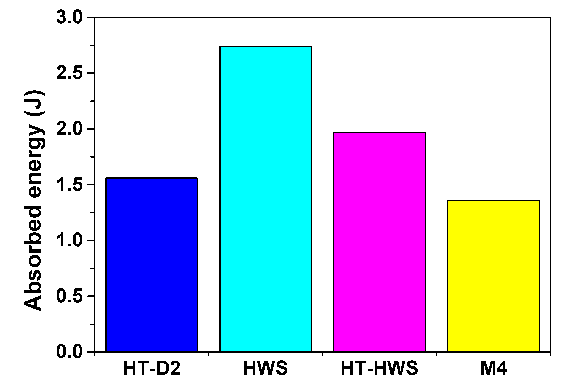
The Charpy test was performed to evaluate the toughness of the deposited materials. Figure 10 shows the experimental results wherein the toughness values are compared. The Charpy test results show the opposite tendency with respect to the hardness and wear resistance. The total absorption energies of the HT-D2, HWS, HT-HWS, and M4-deposited specimens are 1.56 (SD: 0.01), 2.74 (SD: 0.01), 1.96 (SD: 0.352), and 1.36 (SD: 0.346) J, respectively. The hardness and wear resistance of the M4 deposits are higher than those of the HWS deposits, whereas the impact toughness of HWS is higher than those of HT-D2 and M4. Furthermore, the impact toughness of HT-HWS slightly decreases after the post-heat treatment.
Figure 11 shows each of the fractured surfaces. In general, the impact toughness is highly related with the grain boundary and carbides’ precipitation behavior. On the fracture surface of the D2 (substrate), cleavage fractures and fine dimples are observed (Figure 11a). Cleavage fractures are mainly observed in ferrite structures, and dimples represent a ductile fracture. A ductile fracture corresponds to a high absorbed energy. The HT-D2 surface exhibits the intergranular and transgranular fractures with fewer fine dimples (Figure 11b). The HT-D2 toughness was lower because the microstructure is transformed to martensite from ferrite by the heat treatment. In the deposited M4 layer (Figure 11c), intergranular and transgranular fractures were observed without dimples and plastic deformation, which shows the typical brittle characteristic. The cracks originating from the V-notch propagated along the grain boundaries and along the dendrite structure at the interface (Figure 11c,d). Figure 11e shows the fracture surface of the HWS-deposited specimen. The fracture behavior is characteristic of a complex intergranular fracture with dimples. Dendrites were observed at the interface of HWS (Figure 11f). Compared to the M4 deposits, fine dimples were observed in the HWS fracture surface because of the microstructure depending on the chemical composition. The highest toughness of HWS is also attributed to the austenitic matrix. The fracture surface of HT-HWS exhibited different crack propagation characteristics. Although the fracture surface of the deposited layer of HT-HWS is similar to that of the HWS deposited layer (Figure 11g), the martensite fraction in the HT-HWS increased and, in the interface region, the primary rod-like carbides precipitated along grain boundaries by the quenching and tempering, which decreases the toughness. In particular, the eutectic carbide aggregated during the post-heat treatment resulted in a concentration of the stresses, causing cracks to propagate more readily between the grain boundaries. Thus, the absorbed energy was reduced compared to that in HWS, while being higher than that of M4.
4. Conclusions
In this study, HWS alloy was evaluated to verify its applicability to laser deposition and hardfacing of tool steel. To compare the mechanical properties of the deposited HWS with the reference materials (deposited M4 and HT-D2), microstructure observation and mechanical tests, such as hardness, wear, and Charpy impact, were performed. The following conclusions were drawn:
(1) The microstructure of the deposited HWS layer shows cellular and columnar dendrites. The fine microstructure with carbides and the solidification structure of the matrix can be attributed to the high cooling rate of the melting pool generated by the high-power laser. Carbides at the deposited layer and interface were formed by precipitation of chromium-rich M7C3. The HWS deposited layer exhibited excellent hardness, resistance wear, and high toughness. The enhanced mechanical properties of the deposited HWS are strongly correlated with the phase of the microstructure and the characteristics of the carbides.
(2) The HWS deposited layer was subjected to post-deposition heat treatment. The microstructure of the deposited layer of the HT-HWS showed that it underwent a phase transformation, characterized by a reduction in the austenite fraction and an increase in the martensite fraction because of quenching and tempering. Although the toughness of HT-HWS was lower than that of HWS, the hardness and wear resistance improved. Accordingly, it can be concluded that the mechanical properties of the HWS layer can be controlled through the post-heat treatment to satisfy the required properties.
This study lays the foundation for future work on laser melting deposition with HWS powders. The novelty of this study is that it shows that tool steel hardfacing using laser melting with HWS powders is effective. However, we believe that there remain unresolved fundamental questions regarding the fatigue characteristics of HWS deposits. In the future, we aim to perform fatigue tests for durability evaluation of the HWS deposits for possible hardfacing applications.
Author Contributions
This work was done in cooperation with the joint efforts of all the authors. D.S.S. and G.Y.B. designed the experiments; G.Y.B. and G.Y.S. performed the experiments; K.Y.L., G.Y.B. and D.S.S. analyzed the experimental data; D.S.S. and G.Y.B. wrote the paper.
Funding
This work was supported by the Korea Institute of Energy Technology Evaluation and Planning (KETEP) funded by the Korea government (MOTIE) (grant number 2018201010633B). Additional support through the National Research Foundation of Korea (NRF) under grant number 2017R1C1B5076047 from the Ministry of Science and ICT is gratefully acknowledged.
Conflicts of Interest
The authors declare no conflict of interest.
References
- Shamsaei, N.; Yadollahi, A.; Bian, L.; Thompson, S.M. An overview of Direct Laser Deposition for additive manufacturing; Part II: Mechanical behavior, process parameter optimization and control. Addit. Manuf. 2015, 8, 12–35. [Google Scholar] [CrossRef]
- Saboori, A.; Gallo, D.; Biamino, S.; Fino, P.; Lombardi, M. An Overview of Additive Manufacturing of Titanium Components by Directed Energy Deposition: Microstructure and Mechanical Properties. Appl. Sci. 2017, 7, 883. [Google Scholar] [CrossRef]
- Telasang, G.; Majumdar, J.D.; Padmanabhan, G.; Manna, I. Structure–property correlation in laser surface treated AISI H13 tool steel for improved mechanical properties. Mater. Sci. Eng. A 2014, 599, 255–267. [Google Scholar] [CrossRef]
- Telasang, G.; Majumdar, J.D.; Padmanabhan, G.; Tak, M.; Manna, I. Effect of laser parameters on microstructure and hardness of laser clad and tempered AISI H13 tool steel. Surf. Coat. Technol. 2014, 258, 1108–1118. [Google Scholar] [CrossRef]
- Wang, S.H.; Chen, J.Y.; Xue, L. A study of the abrasive wear behaviour of laser-clad tool steel coating. Surf. Coat. Technol. 2006, 200, 3446–3458. [Google Scholar] [CrossRef]
- Shim, D.S.; Baek, G.Y.; Lee, E.M. Effect of substrate preheating by induction heater on direct energy deposition of AISI M4 powder. Mat. Sci. Eng. A 2017, 682, 550–562. [Google Scholar] [CrossRef]
- Shim, D.S.; Baek, G.Y.; Lee, S.B.; Yu, J.H.; Choi, Y.S.; Park, S.H. Influence of heat treatment on wear behavior and impact toughness of AISI M4 coated by laser melting deposition. Surf. Coat. Technol. 2017, 328, 219–230. [Google Scholar] [CrossRef]
- Farahmand, P.; Kovacevic, R. An experimental numerical investigation of heat distribution and stress field in single-and multi-track laser cladding by a high-power direct diode laser. Opt. Laser Technol. 2014, 63, 154–168. [Google Scholar] [CrossRef]
- Leunda, J.; Navas, V.G.; Soriano, C.; Sanz, C. Improvement of laser deposited high alloyed powder metallurgical tool steel by a post-tempering treatment. Phys. Procedia 2012, 12, 392–400. [Google Scholar] [CrossRef]
- Leunda, J.; Navas, V.G.; Soriano, C.; Sanz, C. Effect of laser tempering of high alloy powder metallurgical tool steels after laser cladding. Surf. Coat. Technol. 2014, 259, 570–576. [Google Scholar] [CrossRef]
- Baek, G.Y.; Shin, G.Y.; Lee, E.M.; Shim, D.S.; Lee, K.Y.; Yoon, H.S.; Kim, M.H. Mechanical characteristics of a tool steel layer deposited by using direct energy deposition. Met. Mater. Int. 2017, 23, 770–777. [Google Scholar] [CrossRef]
- Baek, G.Y.; Lee, K.Y.; Park, S.H.; Shim, D.S. Effects of substrate preheating during direct energy deposition on microstructure, hardness, tensile strength, and notch toughness. Met. Mater. Int. 2017, 23, 1204–1215. [Google Scholar] [CrossRef]
- Briki, J.; Slima, S.B. A New Continuous Cooling Transformation Diagram for AISI M4 High-Speed Tool Steel. J. Mater. Eng. Perform. 2008. [Google Scholar] [CrossRef]
- Ramírez, G.; Mestra, A.; Casas, B.; Valls, I.; Martínez, R.; Bueno, R.; Góez, A.; Mateo, A.; Llanes, L. Influence of substrate microstructure on the contact fatigue strength of coated cold-work tool steels. Surf. Coat. Technol. 2012, 206, 3069–3081. [Google Scholar] [CrossRef]
- Sapate, S.G.; Chopde, A.D.; Nimbalkar, P.M.; Chandrakar, D.K. Effect of microstructure on slurry abrasion response of En-31 steel. Mater. Des. 2008, 29, 613–621. [Google Scholar] [CrossRef]
- Ueda, M.; Uchino, K.; Kobayashi, A. Effects of carbon content on wear property in pearlitic steels. Wear 2002, 253, 107–113. [Google Scholar] [CrossRef]
- Goto, H.; Amamoto, Y. Effects of varying load on wear resistance of carbon steel under unlubricated conditions. Wear 2003, 254, 1256–1266. [Google Scholar] [CrossRef]
- Lin, Y.C.; Wang, S.W.; Chen, T.M. A study on the wear behavior of hardened medium carbon steel. J. Mater. Process. Technol. 2002, 120, 126–132. [Google Scholar] [CrossRef]
- Nanesa, H.G.; Jahazi, M. Alternative phase transformation path in cryogenically treated AISI D2 tool steel. Mater. Sci. Eng. A 2015, 634, 32–36. [Google Scholar] [CrossRef]
Figure 1.
Micro-images of (a) M4 and (b) HWS (high-wear-resistance steel) spherical powders.

Figure 2.
Schematic of the DED (direct energy deposition) process.

Figure 3.
Schematics of the specimens for the (a) wear test and (b) Charpy impact test (unit: mm).

Figure 4.
Images of the specimen and cross section for XRD (X-ray diffraction) analysis.

Figure 5.
X-ray diffraction patterns of the (a) deposited M4 layer, (b) deposited HWS, and (c) HT-HWS.
Figure 5.
X-ray diffraction patterns of the (a) deposited M4 layer, (b) deposited HWS, and (c) HT-HWS.
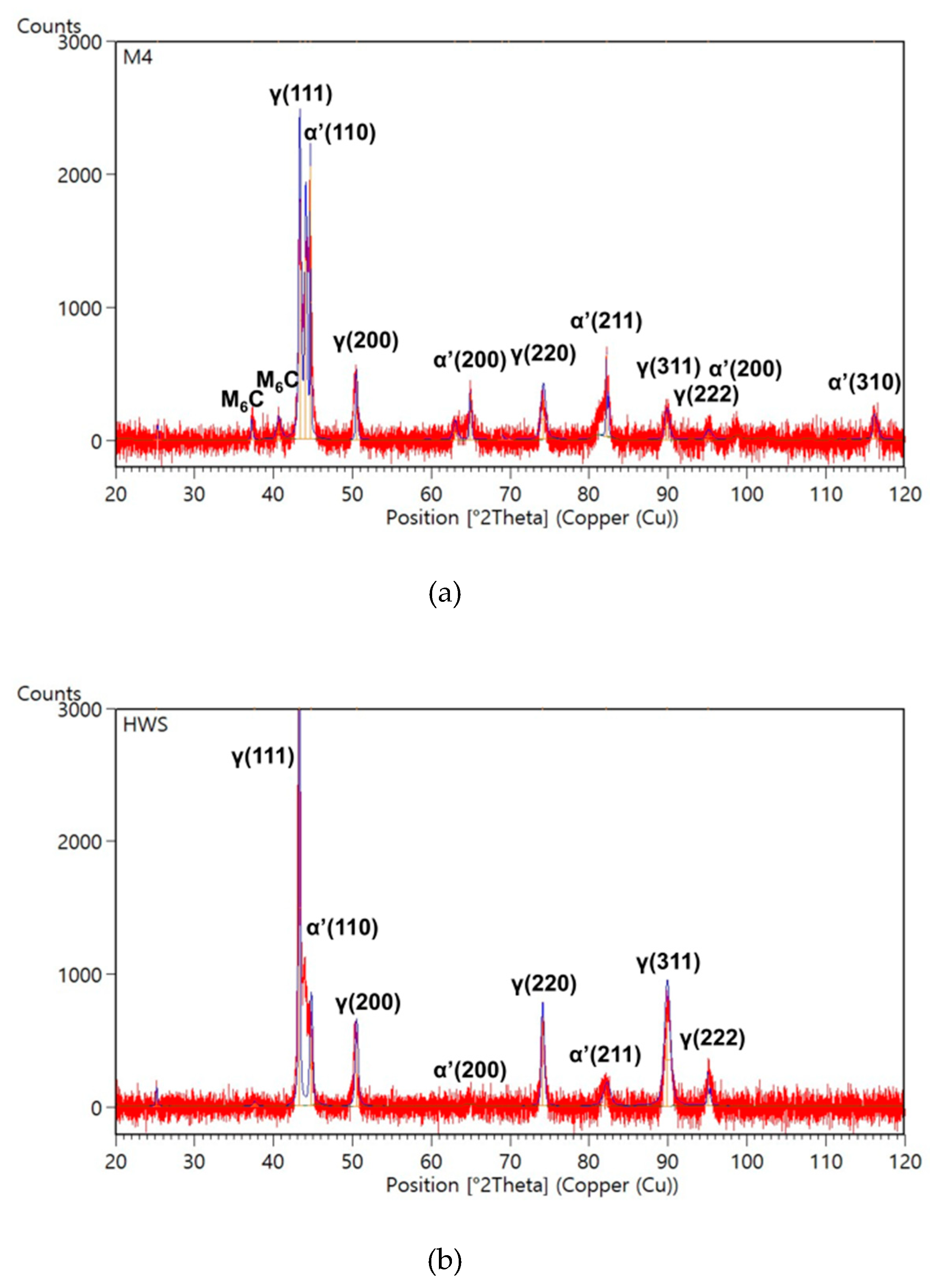

Figure 6.
SEM image and elemental composition of deposition: (a) Deposited M4 region, (b) interface between M4 deposits and substrate, (c) deposited HWS region, (d) interface between HWS deposits and substrate, (e) post-deposition heat treated HWS (HT-HWS) region, and (f) interface region.
Figure 6.
SEM image and elemental composition of deposition: (a) Deposited M4 region, (b) interface between M4 deposits and substrate, (c) deposited HWS region, (d) interface between HWS deposits and substrate, (e) post-deposition heat treated HWS (HT-HWS) region, and (f) interface region.

Figure 7.
Distribution of micro-hardness measured from the top surface of the deposited region to the substrate.
Figure 7.
Distribution of micro-hardness measured from the top surface of the deposited region to the substrate.
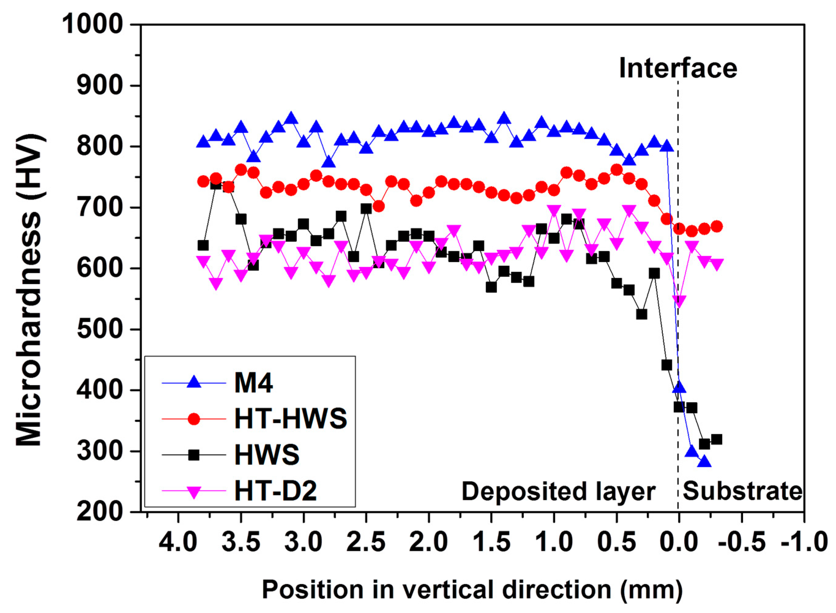
Figure 8.
(a) Images of wear scars after the ball-on-disc wear test, and (b) comparison of weight loss and wear scars.
Figure 8.
(a) Images of wear scars after the ball-on-disc wear test, and (b) comparison of weight loss and wear scars.
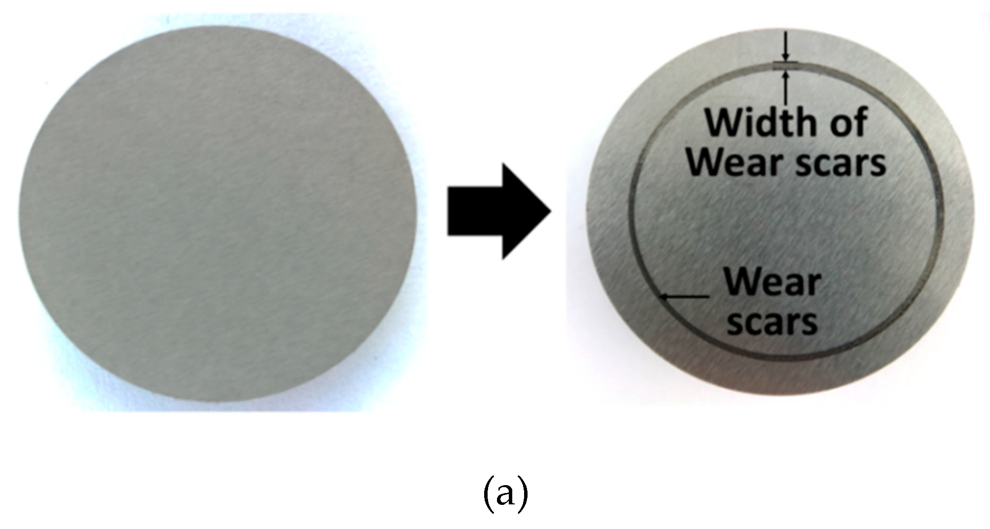

Figure 9.
SEM images showing morphology of the wear scars: (a) HT-D2, (b) M4, (c) HWS, and (d) HT-HWS.
Figure 9.
SEM images showing morphology of the wear scars: (a) HT-D2, (b) M4, (c) HWS, and (d) HT-HWS.

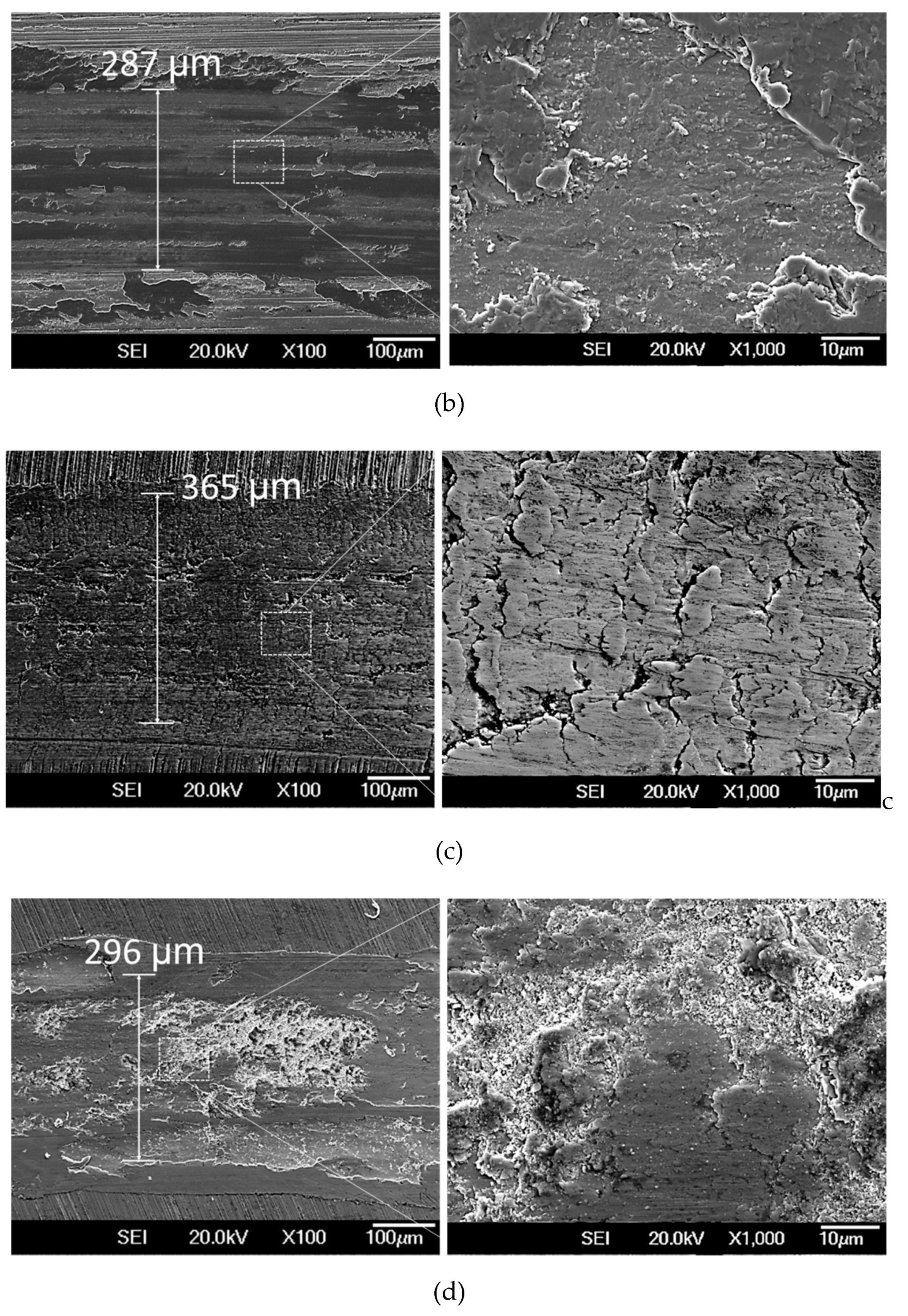
Figure 10.
Total absorbed energy in the Charpy impact test.

Figure 11.
Micro-images of the fracture surface: (a) Substrate D2, (b) HT-D2, (c) deposited M4 layer, (d) interface of the M4 deposits, (e) deposited HWS layer, (f) interface of the HWS deposits, (g) deposited layer of HT-HWS, and (h) interface region of HT-HWS.
Figure 11.
Micro-images of the fracture surface: (a) Substrate D2, (b) HT-D2, (c) deposited M4 layer, (d) interface of the M4 deposits, (e) deposited HWS layer, (f) interface of the HWS deposits, (g) deposited layer of HT-HWS, and (h) interface region of HT-HWS.


Table 1.
Chemical compositions of materials used (wt.%).
| Materials | Element (wt.%) | ||||||||||
|---|---|---|---|---|---|---|---|---|---|---|---|
| C | Si | Mn | P | S | Ni | Cr | Mo | Cu | V | W | |
| AISI D2 (substrate) | 1.56 | 0.24 | 0.25 | 0.025 | 0.001 | 0.175 | 11.31 | 0.83 | 0.14 | 0.25 | - |
| AISI M4 | 1.33 | 0.33 | 0.26 | 0.03 | 0.03 | 0.3 | 4.25 | 4.88 | 0.25 | 4.12 | 5.88 |
| HWS | 1.08 | 1.38 | 0.34 | - | - | - | 7.80 | 1.86 | - | 2.66 | 1.73 |
Table 2.
Processing parameters used.
| Powders | Pre-Heating Temp. (°C) | Laser Power (W) | Scanning Speed (mm/min) | Powder Feed Rate (g/min) | Powder Gas Rate (ℓ/min) | Coaxial Gas Rate (ℓ/min) | Slicing Layer Height (mm) | Overlap Width (mm) |
|---|---|---|---|---|---|---|---|---|
| AISI M4 | 250 | 800 | 850 | 5 | 2.5 | 8 | 0.25 | 0.5 |
| HWS | 20 | 800 | 850 | 5 | 2.5 | 8 | 0.25 | 0.5 |
© 2019 by the authors. Licensee MDPI, Basel, Switzerland. This article is an open access article distributed under the terms and conditions of the Creative Commons Attribution (CC BY) license (http://creativecommons.org/licenses/by/4.0/).
Share and Cite
MDPI and ACS Style
Baek, G.Y.; Shin, G.Y.; Lee, K.Y.; Shim, D.S. Mechanical Properties of Tool Steels with High Wear Resistance via Directed Energy Deposition. Metals 2019, 9, 282. https://doi.org/10.3390/met9030282
AMA Style
Baek GY, Shin GY, Lee KY, Shim DS. Mechanical Properties of Tool Steels with High Wear Resistance via Directed Energy Deposition. Metals. 2019; 9(3):282. https://doi.org/10.3390/met9030282
Chicago/Turabian StyleBaek, Gyeong Yun, Gwang Yong Shin, Ki Yong Lee, and Do Sik Shim. 2019. "Mechanical Properties of Tool Steels with High Wear Resistance via Directed Energy Deposition" Metals 9, no. 3: 282. https://doi.org/10.3390/met9030282
Note that from the first issue of 2016, this journal uses article numbers instead of page numbers. See further details here.