Microstructure and Corrosion Resistance to H2S in the Welded Joints of X80 Pipeline Steel

College of mechanical and automotive engineering, Qilu University of Technology (Shandong Academy of Sciences), Jinan 250353, China
*
Author to whom correspondence should be addressed.
Metals 2019, 9(12), 1325; https://doi.org/10.3390/met9121325
Submission received: 16 November 2019
/
Revised: 29 November 2019
/
Accepted: 4 December 2019
/
Published: 7 December 2019
(This article belongs to the Special Issue Composite Metal Pipes: Properties and Applications)
Abstract
:The microstructure and corrosion resistance in H2S environments for various zones of X80 pipeline steel submerged arc welded joints were studied. The main microstructures in the base metal (BM), welded metal (WM), coarse-grained heat-affected zone (CGHAZ), and fine-grained heat-affected zone (FGHAZ) were mainly polygonal ferrite and granular bainite; acicular ferrite with fine grains; granular bainite, ferrite, and martensite/austenite constituents, respectively. The corrosion behavior differences resulted from the microstructure gradients. The results of the micro-morphologies of the corrosion product films and the electrochemical corrosion characteristics in H2S environments, including open circuit potential and electrochemical impedance spectroscopy, showed that the order of corrosion resistance was FGHAZ > BM > WM > CGHAZ.
1. Introduction
X80 pipeline steel is a low-carbon and low-alloyed steels made by thermo-mechanical controlled rolling technology. Because the special technologies are adopted, its cleanliness is improved, the centerline segregation is reduced, and a more uniform structure is obtained [1]. Thus, X80 pipeline steel with excellent mechanical properties, such as higher strength, better strength, and toughness match, has been used widely around the world [2].
Because of the harsh service environments, pipelines are subject to the threat of corrosion. Hydrogen sulfide (H2S) corrosion, which can cause strong metal dissolution, pitting corrosion, hydrogen embrittlement, hydrogen-induced cracking, and sulfide stress corrosion cracking, is one of the main corrosion types for pipelines [3,4,5]. In H2S environments, the corrosion rate of pipeline steel is mainly related to the temperature, pH value, and H2S partial pressure [6]. With the increase of the temperature and H2S partial pressure, the corrosion rate of pipeline steel decreases first and then increases [7,8]. With the increase of the pH value, the corrosion rate of X80 pipeline steel presents a gradually decreasing trend [9]. Higher H2S partial pressure increases the possibility of serious pitting corrosion in pipeline steel [10]. Hydrogen damage is one of the main reasons for equipment failure in the oil and gas industries [3] because it can embrittle the microstructure of pipeline steel and promote crack growth [11]. The sensitivity of pipeline steel to hydrogen embrittlement is mainly related to metallurgical defects and hydrogen diffusion in the environments [1]. The clearance between martensite/austenite (M/A) constituents is the main hydrogen capture site; thus, the site becomes the crack origin [12]. In H2S environments, a layer of sulfide corrosion product film can be gradually formed on the surface of pipeline steel, and its compact structure is conducive to reducing the corrosion rate [13,14].
There are obvious microstructure and composition gradients in the welded joints, which resulted in different electrochemical behaviors among the base metal (BM), welded metal (WM), and heat-affected zone (HAZ) [15,16,17,18]. It also contributes to enlarging micro-segregation of the anodic and cathodic reaction zones, accelerating the corrosion rate of welded joints and causing them to become more susceptible to dangerous ruptures [19]. Thus, the welded joints are considered to be the weak zone of corrosion resistance in pipeline steel. The order of the corrosion resistance of X80 pipeline steel welded joints is BM > HAZ > WM in an alkaline soil solution [20]. The order of corrosion current density of X65 pipeline steel welded joints is HAZ > BM > WM in the acidic environment [21]. Low-temperature transition microstructures with high hardness in the welded joint, like bainite and M/A constituents, are more susceptible to corrosion [22]. In addition, the coarsening of the microstructure increases the corrosion resistance of welded joints in acidic solutions containing Cl− [23]. The proper heat treatment can enhance the corrosion resistance in the welded joints through adjusting the microstructure and eliminating the residual stress, but the corrosion resistance of HAZ is still inferior to that of BM [24,25], and the cost of heat treatment is also high.
The corrosion behaviors of the welded joints are difficult to control and predict [23,24,26]. There are few studies on the H2S corrosion behaviors of the welded joints. In this study, the H2S corrosion resistance and the characteristics of the sulfide corrosion products of the X80 pipeline steel submerged arc welding (SAW) joints were studied.
2. Experimental Procedures
2.1. Materials
Samples used in this work were cut from the X80 pipeline steel SAW joint. The thickness of the welded steel plate was 26.4 mm, and the heat input was taken as 30 kJ/cm. The alloy content of the BM and WM (wt.%) are shown in Table 1.
2.2. Microstructure and Micro-Morphologies of Corrosion Product Observations
The microstructure observations of the welded joint were performed by VHX_500F KEYENCE (Shenzhen senmeirui Technology Co. LTD, Shenzhen, China) optical microscope. The corrosion product film covering the surface of the substrate was characterized by scanning electron microscopy (SEM, JSM-6480LA, Shenzhen Kaiyu Technology Co. LTD, Chuo-ku, Japan) coupled with energy-dispersive X-ray spectroscopy (EDS). Crystal structures were characterized by X-ray diffractometer (XRD, DX-2700, Dandong Haoyuan Instrument Co. LTD, Dangdong, China) with a scanning step of 0.5°/min. The micro-hardness distribution in the welded joint was determined by a micro-hardness instrument (HXD-1000TMC, Xian Weixin Testing Equipment Co. LTD, Xi’an, China) with a load charge of 200 g for 15 s [27].
2.3. Electrochemical Experiments
The electrochemical experiments were performed using Autolab (Aut84886, Shanghai Walong Instrument Co. LTD, Shanghai, China) with a two-component cell, Pt gauze counter electrode, and saturated calomel electrode (SCE) of + 0.241 VSHE as the reference electrode [28]. The samples used for the electrochemical experiments were machined to be a rectangular shape with dimensions 10 mm × 10 mm × 2 mm. The specimens were ground using an 800 grit emery paper, then cleaned sequentially with acetone, alcohol, and distilled water. A 5 wt.% NaCl solution was chosen in the present work, and the temperature was fixed at 55 °C. Before the electrochemical experiments, the solution was purged with H2S for 24 h, and H2S flow was maintained during the test duration. The open circuit potential (OCP) and electrochemical impedance spectroscopy (EIS) were tested with different immersion times to study the electrochemical behaviors of the samples. EIS was performed with 10 mV amplitude and frequencies ranging from 105 to 10−2 Hz; the results were fitted by the software of ZSimpWin (Echem Software Version 3.21).
3. Results and Discussion
3.1. Microstructure Evolution
The microstructure of the welded joint is shown in Figure 1. It was observed that the microstructure of BM was mainly polygonal ferrite (PF) with fine grain size and a little granular bainite (GB), embellished by M/A constituents. The microstructure of WM was mainly acicular ferrite (AF) with fine grains, where AF was nucleated within the austenite grain [29]. The microstructure of the coarse-grained heat-affected zone (CGHAZ) was mainly GB, and the prior austenite grain boundaries (PAGB) were embellished by M/A constituents. The microstructure of the fine-grained heat-affected zone (FGHAZ) was composed of PF and M/A constituents; the M/A constituents distributed uniformly in the PF grain boundaries. We found that the content, shape, distribution, and size of the M/A constituents had an important influence on the performance of the CGHAZ and FGHAZ.
The micro-hardness distribution of the welded joints of X80 pipeline steel is shown in Figure 2. It could be seen that the hardness in the WM was the highest and relatively uniform, maintained at 230–240 HV. The hardness of the CGHAZ near the weld was higher than that of the BM because of the high hardness microstructure in the CGHAZ, like the GB and M/A constituents. The lowest point of micro-hardness appeared in the HAZ close to the BM, maintained at 170–180 HV, which might be due to the lower peak welding temperature in the zone. These findings were in accordance with the results of the microstructure.
3.2. Corrosion Resistance Analysis in H2S Environments
3.2.1. Open Circuit Potential (OCP)
The OCP of BM, WM, CGHAZ, and FGHAZ in 5 wt.% NaCl solution saturated with H2S at 55 °C is shown in Figure 3. It was observed that the OCP was dependent on the immersion time, and it increased in the immersion processes for all samples, which could be attributed to the generation of a sulfur-rich film on the steel surface that has been discussed later. In addition, the galvanic series at the studied immersion times were the same as FGHAZ > BM >WM > CGHAZ, which indicated that a serious galvanic effect could be introduced when the welded joint was immersed in the electrolyte as a whole [28]. The CGHAZ would be attacked preferentially because of its lower potentials.
3.2.2. Electrochemical Impedance Spectroscopy (EIS)
In order to study the corrosion mechanisms of the X80 pipeline steel welded joint, EIS analysis was performed. The Nyquist impedance diagrams of different zones in the immersion process are shown in Figure 4. It was observed that Nyquist plots of all samples showed similar patterns under different immersion times. All Nyquist graphs contained two capacitive reactance loops. The capacitance arc in a high-frequency area corresponds to the electric double layer, and the capacitive reactance arc in the low-frequency region corresponds to the corrosion process [28]. The radius of the 8 h capacitive reactance arc was larger than that of the 24 h; the corrosion products during this period might undergo phase transformation and diffusion, and this phenomenon is related to the phase transformation and diffusion of corrosion products [30]. Thus, the dynamic corrosion products were the reason for the decline of the corrosion resistance from 8 h to 24 h. Corrosion products accumulated until the welded joints were completely covered, causing increased thickness of the corrosion products film, and the enhanced stability of the film resulted in an increased radius of the capacitive reactance arc after 24 h.
The equivalent circuit of RS (Qf(Rf(CdlRct)) [31,32] is shown in Figure 5, in which Rs is the solution resistance, Rf is the corrosion product film resistance, Cdl is the double-layer capacitance, Rct is the charge transfer resistance, and Qf is the constant-phase element (CPE) of the corrosion product films. The term is the CPE power is related to the depression angle under the real axis, which expresses the CPE impedance as follows:
For , CPE indicates an ideal capacitor [25,33]. The fitting results of Rf and Rct, which represent the corrosion resistance, are shown in Figure 6. It could be seen that the Rf and Rct increased in the initial immersion of 8 h, which could be attributed to the continuous accumulation of the corrosion products on the surface of the sample as the immersion time of the sample increased. The sloughing of corrosion products and the phase transformation were responsible for the decrease of the Rf and Rct from 8 to 24 h. The Rf and Rct increased after 24 h. This phenomenon showed that the surface was covered with a corrosion product film, and corrosion product films were protective in these experimental conditions [34].
More importantly, Rf and Rct represented the corrosion resistance. The order of corrosion resistance was the FGHAZ > BM > WM > CGHAZ across all whole immersion stages, which was in the consistency with the OCP results.
3.2.3. Characterization of the Corrosion Product Films
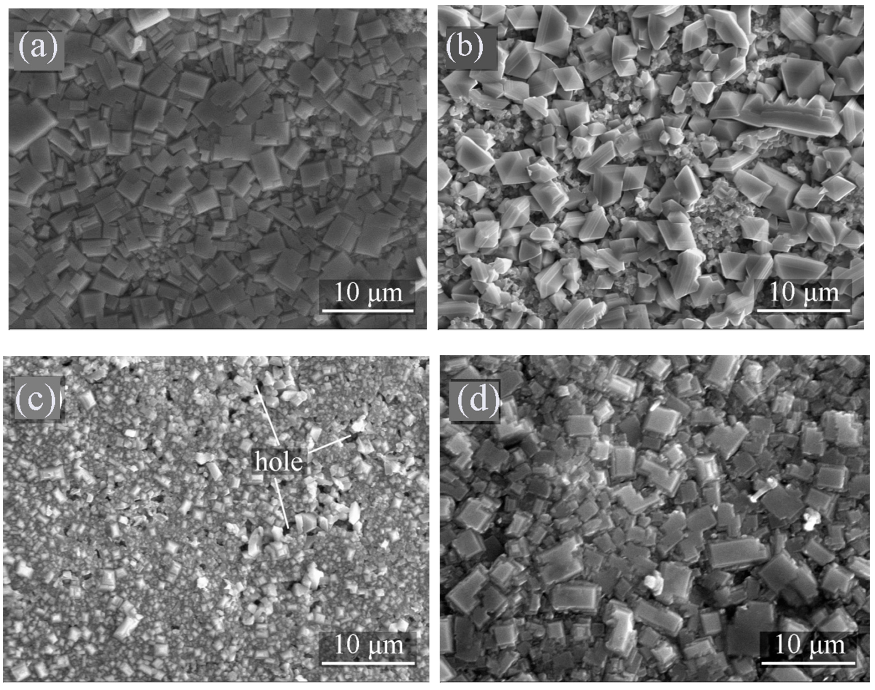
The micrographs of the corrosion products produced on the surface of the BM, WM, CGHAZ, and FGHAZ after immersion for 96 h are shown in Figure 7. The corresponding EDS results are shown in Table 2. The EDS results also showed that the ratio of Fe to S for the corrosion products was about 1:1 after immersion for 96 h. In addition, the XRD results (not shown in this paper) showed that the crystal structure of the corrosion product formed on the surface of all samples was mackinawite. Mackinawite is a thermodynamically semi-stable form of sulfide, and cubic FeS can easily transform into mackinawite [35,36]. The composition and the crystal structure of the corrosion products after immersion for 96 h were independent of the composition and the microstructure of the steel. A film with a mixture of mackinawite and other sulfide provides more protection than the mackinawite film [37]. With an increase of the immersion time, H2S partial pressure, and temperature, other crystal structures might be formed.
However, the shape, size, compactness, and density of the corrosion products for different samples after immersion for 96 h were different, which was responsible for the different corrosion resistance values. A layer of irregularly rectangular, slab-like corrosion products was formed on the surface of the BM, and the corrosion products were closely arranged without any holes. It could be predicted that the film could slow down the corrosion rate and prevent the underlying steel from further dissolution. The appearance of the corrosion products on the surface of the WM occurred in a four-prismatic shape, and the arrangement density was worse compared with the BM. The size of the corrosion products formed on the surface of the CGHAZ was smaller than that of BM and WM. There were many holes in the corrosion products formed on the surface of the CGHAZ, which could significantly affect the corrosion resistance [38]. The presence of the holes was conducive to the charge exchange between the surface of the CGHAZ and the electrolyte, causing a decline of the corrosion resistance. It was anticipated that cracks could be extended along the direction of external forces due to the holes [25]. The different morphologies of the corrosion product film showed that the nucleation and growth process of the products were different, but the specific mechanisms need to be further studied.
3.2.4. Analysis of the Differences in Corrosion Resistance for Different Zones
The results showed the order of corrosion resistance was FGHAZ > BM > WM > CGHAZ. Therefore, the corrosion resistance of the BM and WM was similar, and WM and BM were better matched in corrosion resistance. The corrosion resistance of the WM could be enhanced by adjusting the chemical composition, such as by adding Cu and Cr to the welding materials [39]. Significant differences in H2S corrosion resistance existed between the FGHAZ and CGHAZ because of microstructure differences. The microstructure of FGHAZ was mainly PF with fine grain size, and the corrosion products were most closely arranged, the corrosion resistance was the best, even better than that of BM. The CGHAZ showed a large number of coarse non-equilibrium microstructures. The differences in OCP could introduce galvanic corrosion [5]. The CGHAZ could be preferentially attacked, leading to the CGHAZ having the lowest Rct and the loosest corrosion product film. Therefore, the CGHAZ was considered to be the weak zone of corrosion resistance of welded joints.
4. Conclusions
- (1)
- In the X80 pipeline steel submerged arc welded joint, the microstructure of BM, WM, CGHAZ, and FGHAZ was mainly PF + GB, AF, GB, PF + M/A constituents with fine grains, respectively.
- (2)
- The WM showed the highest hardness, and the HAZ near the BM showed the lowest hardness in the welded joint.
- (3)
- The CGHAZ showed the lowest open circuit potential, indicating that it would be attacked preferentially when the welded joint is immersed in the electrolyte as a whole.
- (4)
- In the H2S environments, the order of corrosion resistance of X80 pipeline steel submerged arc welded joints was FGHAZ > BM> WM > CGHAZ. The CGHAZ was the weak zone of corrosion resistance of the welded joint.
- (5)
- The composition and structure of the corrosion products were not affected by the difference of composition and crystal structure of the welded joint. But the micromorphology was quite different, which was the reason for the difference of corrosion resistance.
Author Contributions
The contribution of each author made to the manuscript is as follows: J.-B.W., writing of the draft; G.-C.X., data analysis; W.Z., writing and revising; B.-R.Z., research design; and W.-F.R., research design and data analysis.
Acknowledgments
The work was supported by the National Nature Science Foundation of China (No. 51805285), the Project funded by China Postdoctoral Science Foundation (2019M661016), the Natural Science Foundation of Shandong Province of China (ZR2017LEE011), and the Key Research and Development Project of Shandong Province (2018GGX103031).
Conflicts of Interest
The authors declare no conflicts of interest.
References
- Sha, Q.; Li, D. Microstructure, mechanical properties and hydrogen induced cracking susceptibility of X80 pipeline steel with reduced Mn content. Mater. Sci. Eng. A 2013, 585, 214–221. [Google Scholar] [CrossRef]
- Jia, Y.Z.; Wang, J.Q.; Han, E.H.; Ke, W. Stress corrosion cracking of X80 pipeline steel in near-neutral pH environment under constant load tests with and without preload. J. Mater. Sci. Technol. 2011, 27, 1039–1046. [Google Scholar] [CrossRef]
- Zhou, C.; Zheng, S.; Chen, C.; Lu, G. The effect of the partial pressure of H2S on the permeation of hydrogen in low carbon pipeline steel. Corros. Sci. 2013, 67, 184–192. [Google Scholar] [CrossRef]
- Al-Mansour, M.; Alfantazi, A.M.; El-Boujdaini, M. Sulfide stress cracking resistance of API-X100 high strength low alloy steel. Mater. Des. 2009, 30, 4088–4094. [Google Scholar] [CrossRef]
- Huang, F.; Liu, J.; Deng, Z.J.; Cheng, J.H.; Lu, Z.H.; Li, X.G. Effect of microstructure and inclusions on hydrogen induced cracking susceptibility and hydrogen trapping efficiency of X120 pipeline steel. Mater. Sci. Eng. A 2010, 527, 6997–7001. [Google Scholar] [CrossRef]
- Qiu, Z.; Xiong, C.; Chang, Z.; Zhao, Z.; Zhao, C.; Ye, Z. Major corrosion factors in the CO2 and H2S coexistent environment and the relative anti-corrosion method: Taking Tazhong I gas field, Tarim Basin, as an example. Petrol. Explor. Dev. 2012, 39, 256–260. [Google Scholar] [CrossRef]
- Bi, F.Q.; Zhang, X.Y.; Yong, W.; Sun, L.L.; Yang, W. Research on Stress Corrosion Behavior of X70 Pipeline Steel in H2S Environment. J. Mater. Eng. 2009, 8, 18–23. [Google Scholar]
- Li, W.F.; Zhou, Y.J.; Xue, Y. Corrosion Behavior of 110S Tube Steel in Environments of High H2S and CO2 Content. J. Iron. Steel Res. Int. 2012, 19, 59–65. [Google Scholar] [CrossRef]
- Fei, X.D.; Ming, W. Effect of dissolved oxygen on corrosion behavior of X80 pipeline steel and its mechanism. J. Iron. Steel Res. Int. 2015, 27, 60–65. [Google Scholar]
- Ren, C.; Liu, D.; Bai, Z.; Li, T. Corrosion behavior of oil tube steel in simulant solution with hydrogen sulfide and carbon dioxide. Mater. Chem. Phys. 2005, 93, 305–309. [Google Scholar] [CrossRef]
- Han, Y.D.; Jing, H.Y.; Xu, L.Y. Welding heat input effect on the hydrogen permeation in the X80 steel welded joints. Mater. Chem. Phys. 2012, 132, 216–222. [Google Scholar] [CrossRef]
- Wang, H.K.; Luu, W.C.; Ho, K.F.; Wu, J.K. Hydrogen permeation in a submerged arc weldment of TMCP steel. Mater. Chem. Phys. 2003, 77, 447–454. [Google Scholar] [CrossRef]
- Bai, P.; Zheng, S.; Zhao, H.; Ding, Y.; Wu, J.; Chen, C. Investigations of the diverse corrosion products on steel in a hydrogen sulfide environment. Corros. Sci. 2014, 87, 397–406. [Google Scholar] [CrossRef]
- Ozekmekci, M.; Salkic, G.; Fellah, M.F. Use of zeolites for the removal of H2S: A mini-review. Fuel Process. Technol. 2015, 139, 49–60. [Google Scholar] [CrossRef]
- Wang, L.W.; Liu, Z.Y.; Cui, Z.Y.; Du, C.W.; Wang, X.H.; Li, X.G. In situ corrosion characterization of simulated weld heat affected zone on API X80 pipeline steel. Corros. Sci. 2014, 85, 401–410. [Google Scholar] [CrossRef]
- Eliyan, F.F.; Alfantazi, A. Corrosion of the Heat-Affected Zones (HAZs) of API-X100 pipeline steel in dilute bicarbonate solutions at 90 °C-An electrochemical evaluation. Corros. Sci. 2013, 74, 297–307. [Google Scholar] [CrossRef]
- Zhu, J.; Xu, L.; Feng, Z.; Frankel, G.S.; Lu, M.; Chang, W. Galvanic corrosion of a welded joint in 3Cr low alloy pipeline steel. Corros. Sci. 2016, 111, 391–403. [Google Scholar] [CrossRef]
- Wang, P.; Lv, Z.; Zheng, S.; Qi, Y.; Wang, J.; Zheng, Y. Tensile and impact properties of X70 pipeline steel exposed to wet H2S environments. Int. J. Hydrogen Energy 2015, 40, 11514–11521. [Google Scholar] [CrossRef]
- Papadakis, G. Major hazard pipelines: A comparative study of onshore transmission accidents. J. Loss Prev. Process Ind. 1999, 12, 91–107. [Google Scholar] [CrossRef]
- Yang, T.; Liu, Z.Y.; Zhao, J.; Ju, D.; Yu, Z.G. Research of Corrosion Resistance of Welded API X80 Steel. Mater. Port. 2019, 52, 44–47. (In Chinese) [Google Scholar]
- Xing, Y.Y.; Liu, Z.Y.; Du, C.W.; Li, X.G.; Liu, R.K.; Zhu, M. Influence of H2S concentration and pH value on corrosion behavior of weld joint of X65 subsea pipeline steel. J. Chin. Soc. Corros. Prot. 2014, 34, 231–236. [Google Scholar]
- Hemmingsen, T.; Hovdan, H.; Sanni, P.; Aagotnes, N.O. The influence of electrolyte reduction potential on weld corrosion. Electrochim. Acta 2002, 47, 3949–3955. [Google Scholar] [CrossRef]
- Huang, H.H.; Wen, T.T.; Ju, T.L. The influences of microstructure and composition on the electrochemical behaviour of a516 steel weldment. Corros. Sci. 1994, 36, 1027–1038. [Google Scholar] [CrossRef]
- Bordbar, S.; Alizadeh, M.; Hashemi, S.H. Effects of microstructure alteration on corrosion behavior of welded joint in API X70 pipeline steel. Mater. Des. 2013, 45, 597–604. [Google Scholar] [CrossRef]
- Alizadeh, M.; Bordbar, S. The influence of microstructure on the protective properties of the corrosion product layer generated on the welded API X70 steel in chloride solution. Corros. Sci. 2013, 70, 170–179. [Google Scholar] [CrossRef]
- Kong, D.J.; Wu, Y.Z.; Long, D. Stress Corrosion of X80 Pipeline Steel Welded Joints by Slow Strain Test in NACE H2S Solutions. J. Iron. Steel Res. Int. 2013, 20, 40–46. [Google Scholar] [CrossRef]
- Zhang, G.A.; Cheng, Y.F. Micro-electrochemical characterization of corrosion of welded X70 pipeline steel in near-neutral pH solution. Corros. Sci. 2009, 51, 1714–1724. [Google Scholar] [CrossRef]
- Zhao, W.; Zou, Y.; Matsuda, K.; Zou, Z. Corrosion behavior of reheated CGHAZ of X80 pipeline steel in H2S-containing environments. Mater. Des. 2016, 99, 44–56. [Google Scholar] [CrossRef]
- Zhang, G.A.; Cheng, Y.F. Micro-electrochemical characterization and Mott–Schottky analysis of corrosion of welded X70 pipeline steel in carbonate/bicarbonate solution. Electrochim. Acta 2009, 55, 316–324. [Google Scholar] [CrossRef]
- Bai, P.; Zhou, H.; Zheng, S.; Chen, C. Initiation and development stages of steel corrosion in wet H2S environments. Corros. Sci. 2015, 93, 109–119. [Google Scholar] [CrossRef]
- Qi, Y.; Luo, H.; Zheng, S.; Chen, C.; Lv, Z.; Xiong, M. Effect of H2S partial pressure on the tensile properties of A350LF2 steel in the absence and presence of pre-immersion. Mater. Sci. Eng. A 2014, 609, 161–167. [Google Scholar] [CrossRef]
- Lucio-Garcia, M.A.; Gonzalez-Rodriguez, J.G.; Casales, M.; Martinez, L.; Chacon-Nava, J.G.; Neri-Flores, M.A. Effect of heat treatment on H2S corrosion of a micro-alloyed C-Mn steel. Corros. Sci. 2009, 51, 2380–2386. [Google Scholar] [CrossRef]
- Díaz, B.; Härkönen, E.; Światowska, J.; Maurice, V.; Seyeux, A.; Marcus, P. Low-temperature atomic layer deposition of Al2O3 thin coatings for corrosion protection of steel: Surface and electrochemical analysis. Corros. Sci. 2011, 53, 2168–2175. [Google Scholar] [CrossRef]
- Bai, P.; Zheng, S.; Chen, C. Electrochemical characteristics of the early corrosion stages of API X52 steel exposed to H2S environments. Mater. Chem. Phys. 2015, 149–150, 295–301. [Google Scholar] [CrossRef]
- Rickard, D.; Morse, J.W. Acid volatile sulfide (AVS). Mar. Chem. 2005, 97, 141–197. [Google Scholar] [CrossRef]
- Andrzej, A.; Patrick, J.S. A computational approach to predicting the formation of iron sulfide species using stability diagrams. Comput. Geosci. 1997, 23, 647–658. [Google Scholar]
- Zhou, C.; Chen, X.; Wang, Z.; Zheng, S.; Li, X.; Zhang, L. Effects of environmental conditions on hydrogen permeation of X52 pipeline steel exposed to high H2S-containing solutions. Corros. Sci. 2014, 89, 30–37. [Google Scholar] [CrossRef]
- Zhou, W.; Zhou, Y.; Matsuda, K.; Zou, Z. Characterization of the effects of hydrogen sulfide on the corrosion of X80 pipeline steel in saline solution. Corros. Sci. 2016, 102, 455–468. [Google Scholar] [CrossRef]
- Chen, X.W.; Liao, B.; Qiao, G.Y.; Gu, Y.; Wang, X.; Xiao, F.R. Effect of Nb on mechanical properties of HAZ for high-Nb X80 pipeline steels. J. Iron. Steel Res. Int. 2013, 20, 53–60. [Google Scholar] [CrossRef]
Figure 1.
The microstructure of the X80 pipeline steel welded joints of the (a) BM (base metal), (b) WM (welded metal), (c) CGHAZ (coarse-grained heat-affected zone), and (d) FGHAZ (fine-grained heat-affected zone).
Figure 1.
The microstructure of the X80 pipeline steel welded joints of the (a) BM (base metal), (b) WM (welded metal), (c) CGHAZ (coarse-grained heat-affected zone), and (d) FGHAZ (fine-grained heat-affected zone).
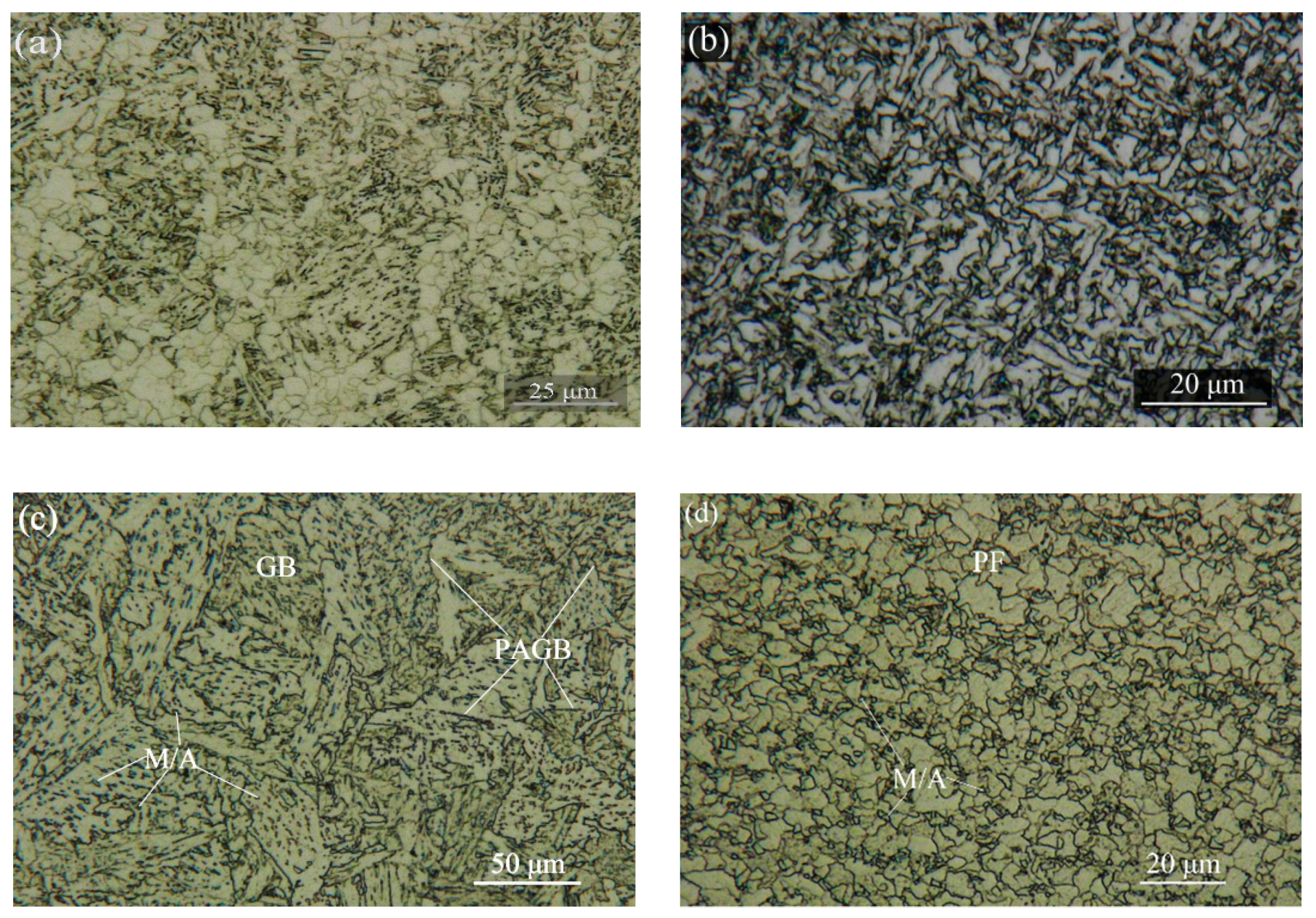
Figure 2.
Micro-hardness distribution of the X80 pipeline steel welded joint.

Figure 3.
The OCP (open circuit potential) of different zones in 5 wt.% NaCl solution saturated with H2S at 55 °C.
Figure 3.
The OCP (open circuit potential) of different zones in 5 wt.% NaCl solution saturated with H2S at 55 °C.

Figure 4.
The Nyquist impedance diagrams in different immersion times in 5 wt.% NaCl solution saturated with H2S at 55 °C of (a) BM, (b) WM, (c) CGHAZ, and (d) FGHAZ.
Figure 4.
The Nyquist impedance diagrams in different immersion times in 5 wt.% NaCl solution saturated with H2S at 55 °C of (a) BM, (b) WM, (c) CGHAZ, and (d) FGHAZ.
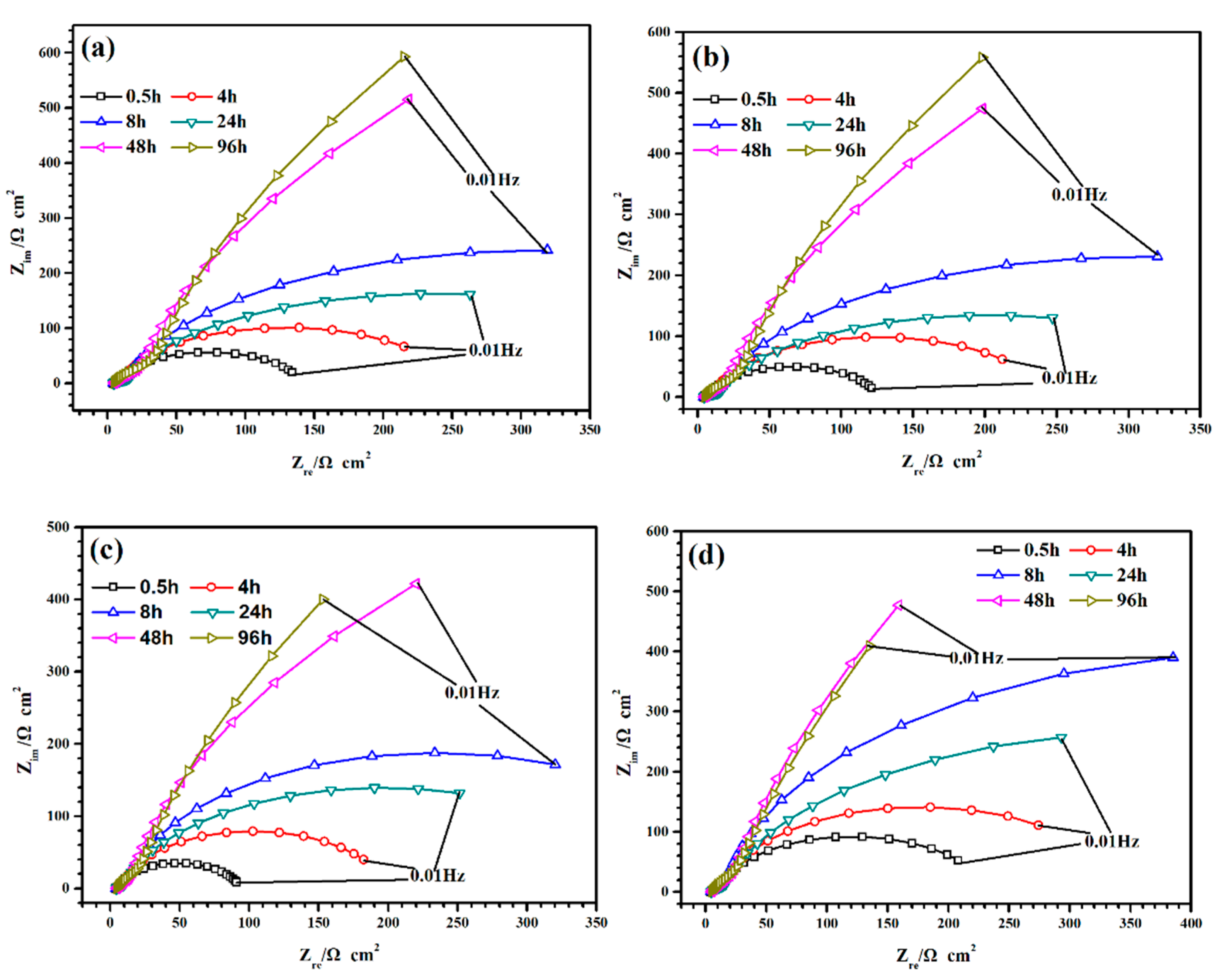
Figure 5.
Electrochemical equivalent of RS (Qf(Rf(CdlRct)) for EIS (electrochemical impedance spectroscopy) fitting.
Figure 5.
Electrochemical equivalent of RS (Qf(Rf(CdlRct)) for EIS (electrochemical impedance spectroscopy) fitting.

Figure 6.
Fitting results of the corrosion product film resistance Rf and charge transfer resistance Rct under different immersion times of (a) Rf and (b) Rct.
Figure 6.
Fitting results of the corrosion product film resistance Rf and charge transfer resistance Rct under different immersion times of (a) Rf and (b) Rct.
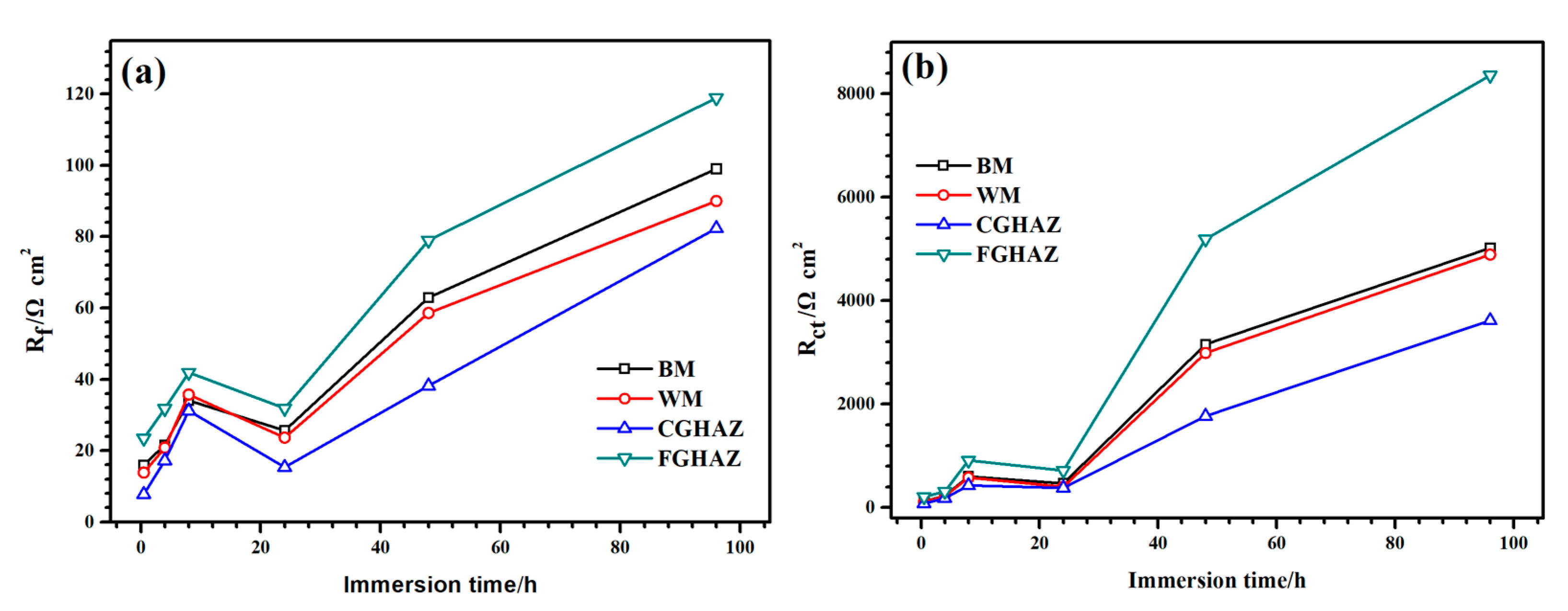
Figure 7.
SEM of the corrosion products produced on the surface of the (a) BM, (b) WM, (c) CGHAZ, and (d) FGHAZ after immersion for 96 h.
Figure 7.
SEM of the corrosion products produced on the surface of the (a) BM, (b) WM, (c) CGHAZ, and (d) FGHAZ after immersion for 96 h.

Table 1.
The alloy composition of the BM (base metal) and WM (welded metal). (wt.%).
| Material | C | Si | Mn | Al | V | Ni | Cr | Mo | Ti | Cu | Nb |
|---|---|---|---|---|---|---|---|---|---|---|---|
| BM | 0.046 | 0.305 | 1.760 | 0.058 | 0.008 | 0.225 | 0.023 | 0.226 | 0.015 | 0.215 | 0.079 |
| WM | 0.062 | 0.380 | 1.830 | 0.030 | 0.004 | 0.190 | 0.204 | 0.090 | 0.013 | 0.200 | 0.040 |
Table 2.
Corresponding EDS results of corrosion products produced on the surface of the BM, WM, CGHAZ (coarse-grained heat-affected zone), and FGHAZ (fine-grained heat-affected zone) after immersion for 96 h. (the content in parentheses is the standard deviations).
Table 2.
Corresponding EDS results of corrosion products produced on the surface of the BM, WM, CGHAZ (coarse-grained heat-affected zone), and FGHAZ (fine-grained heat-affected zone) after immersion for 96 h. (the content in parentheses is the standard deviations).
| Material | BM | WM | CGHAZ | FGHAZ |
|---|---|---|---|---|
| Fe (at %) | 44.82 (1.21) | 46.83 (1.26) | 45.12 (1.15) | 45.83 (1.28) |
| S (at %) | 55.18 (1.21) | 53.17 (1.26) | 54.88 (1.15) | 54.17 (1.28) |
| Fe/S | 1.23 (0.11) | 1.14 (0.13) | 1.22 (0.09) | 1.18 (0.15) |
© 2019 by the authors. Licensee MDPI, Basel, Switzerland. This article is an open access article distributed under the terms and conditions of the Creative Commons Attribution (CC BY) license (http://creativecommons.org/licenses/by/4.0/).
Share and Cite
MDPI and ACS Style
Wang, J.-B.; Xiao, G.-C.; Zhao, W.; Zhang, B.-R.; Rao, W.-F. Microstructure and Corrosion Resistance to H2S in the Welded Joints of X80 Pipeline Steel. Metals 2019, 9, 1325. https://doi.org/10.3390/met9121325
AMA Style
Wang J-B, Xiao G-C, Zhao W, Zhang B-R, Rao W-F. Microstructure and Corrosion Resistance to H2S in the Welded Joints of X80 Pipeline Steel. Metals. 2019; 9(12):1325. https://doi.org/10.3390/met9121325
Chicago/Turabian StyleWang, Jian-Bao, Guang-Chun Xiao, Wei Zhao, Bing-Rong Zhang, and Wei-Feng Rao. 2019. "Microstructure and Corrosion Resistance to H2S in the Welded Joints of X80 Pipeline Steel" Metals 9, no. 12: 1325. https://doi.org/10.3390/met9121325
Note that from the first issue of 2016, this journal uses article numbers instead of page numbers. See further details here.