Article

Effect of Temperature Scheme on Microstructure and Mechanical Properties during Medium Carbon Steel Warm Processing

1
College of Metallurgy and Energy, North China University of Science and Technology, Tangshan 063210, China
2
Key Laboratory of the Ministry of Education for Modern Metallurgy Technology, Tangshan 063210, China
3
School of Materials Science and Engineering, Inner Mongolia University of Technology, Hohhot 010051, China
*
Authors to whom correspondence should be addressed.
Metals 2019, 9(1), 77; https://doi.org/10.3390/met9010077
Submission received: 16 December 2018 / Revised: 3 January 2019 / Accepted: 4 January 2019 / Published: 14 January 2019

Abstract

:
Influence of temperature scheme on the microstructure and properties variation of medium carbon steel warm deformation was studied with testing equipment of Gleeble-3500, SEM, TEM, EBSD, and φ350 reversal rolling mill. The results show that the temperature of 650 facilitates the formation of ultrafine homogeneous microstructure. The microstructure formed during temperature range of 650–700 °C is relative homogeneous and fine. The mechanical properties of warm rolling are influenced by the cooling modes. The lower cooling rate is benefit to the combination of strength and ductility.

1. Introduction

The lightweight characteristic of structure parts is in line with the trend of social development, due to the requirements of cost reduction. However, the loading ability of lightweight structure parts is not allowed to decrease, because of the safety requirement. Therefore, the strength of material has to be increased to a higher level. There are several methods to increase strength. The most cost-optimal way is grain refinement strengthening, among lots of strengthening strategies. Meanwhile, the ductility simultaneously increases with the strength, due to the grain refinement. Now, the main strategies for the refinement of grains can be divided into two types [1,2]. One is the severe plastic deformation (SPD), another is the advanced thermomechanical process (ATP). Due to the limitation of specimen size, the ATP process is more suitable to the industrial production than SPD [1,2]. In terms of grains refined by ATP process, the main methods are shown as follows: deformation-induced transformation (DIT) [3,4,5], cold rolling and annealing (CRA) [6], warm deformation (WD), amongst others. Especially, the DIFT process has been used in the current iron and steel production, due to the excellent practicability. However, the finest grain is about 1.2 μm, produced by deformation-induced ferrite transformation (DIFT), due to the heat released during the high rate cooling process [7]. CRA is a better way to fabricate ultrafine ferrite grains, except for the cost of annealing. Okisu et al. [6] obtained the submicron ferrite grains by the CRA process, with a small strain of 2.8.
If the grain size reaches about 1.0 μm, the strength increases with the decreasing grain size at the cost of ductility. Therefore, other ways are needed to increase the ductility. The methods of increasing ductility include bimodal microstructure [8,9], particle’s pinning [10,11], ductility phase, and others. The results of Ref. [10,11] indicates that carbide particles affected the ductility by pinning the dislocation. Fortunately, the carbide particles can be obtained during medium carbon steel warm deformation. Therefore, the WD process obtained researchers’ attention [12,13].
Yoshitaka et al. [14] pointed out that the proper annealing temperature range for the C–Mn steel warm process is 500–600 °C. Torizuka et al. [15] studied the effect of strain on the microstructure and mechanical properties of low carbon steel at the temperature range of 450–520 °C. Nurty et al. [16] compressed the low carbon steel to the strain of 4.0 during the temperature range of 500–650 °C. Storojevca et al. [13] studied the development of microstructure and texture of medium carbon steel during temperature range of 600–710 °C. Song et al. [17] pointed out that the process composed of WD at temperature of 550 °C and annealing is of benefit to the uniform microstructure. It is obvious that the temperature range of 450–710 °C is too wide to be selected. It is a challenge how to determine the proper WD temperature. However, research regarding the effect of temperature range on microstructure and mechanical properties evolution of carbon steel WD process is rare. Moreover, the effect of cooling mode of WD on the microstructure and mechanical properties is also rarely analyzed. Storojeva et al. [13] and Song et al. [17] proposed that annealing is beneficial to the homogeneity of microstructure. Can the annealing process be replaced by low rate cooling? If that is acceptable, it is worthy to do it. Therefore, in this research, the effect of temperature range and cooling mode on the microstructure and properties was discussed.

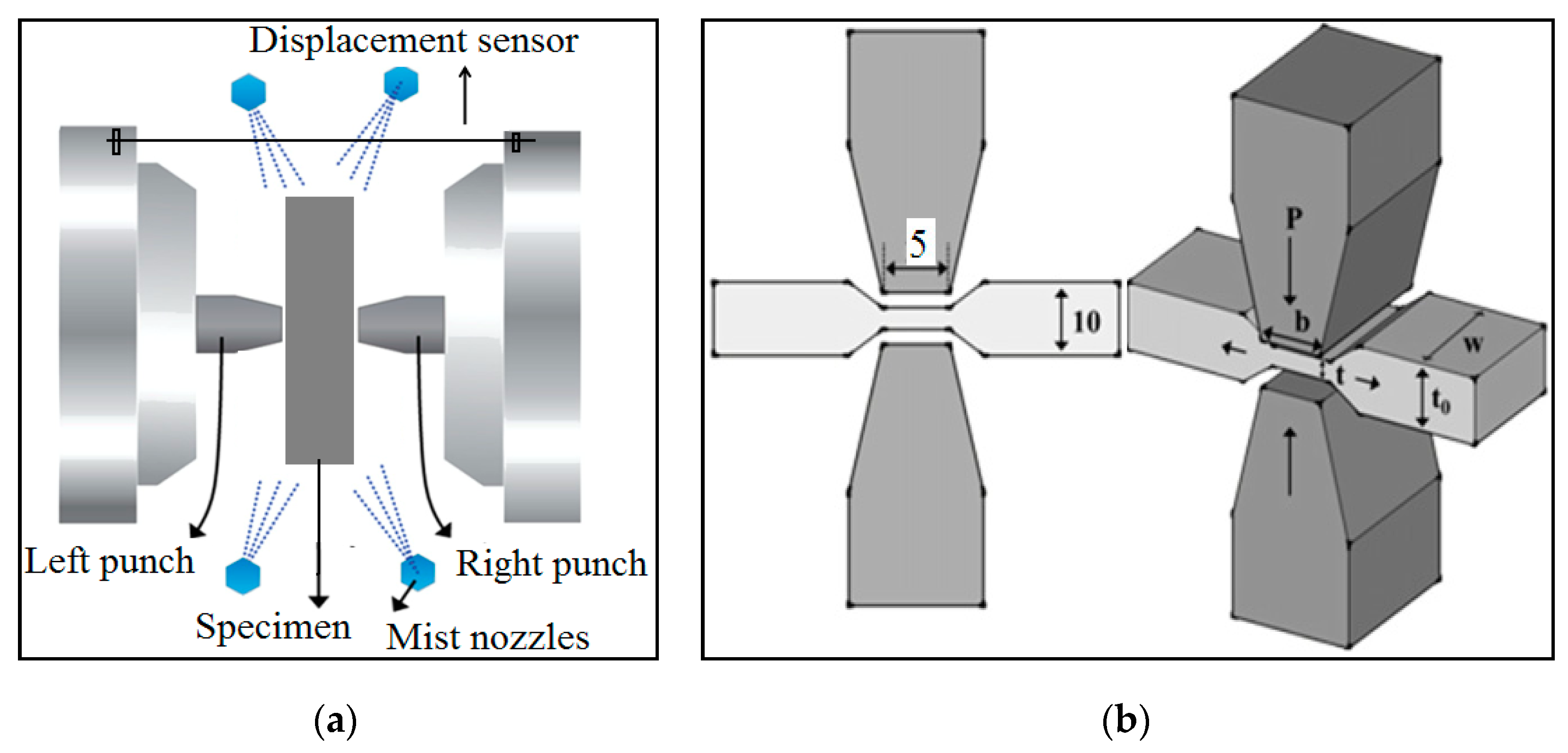
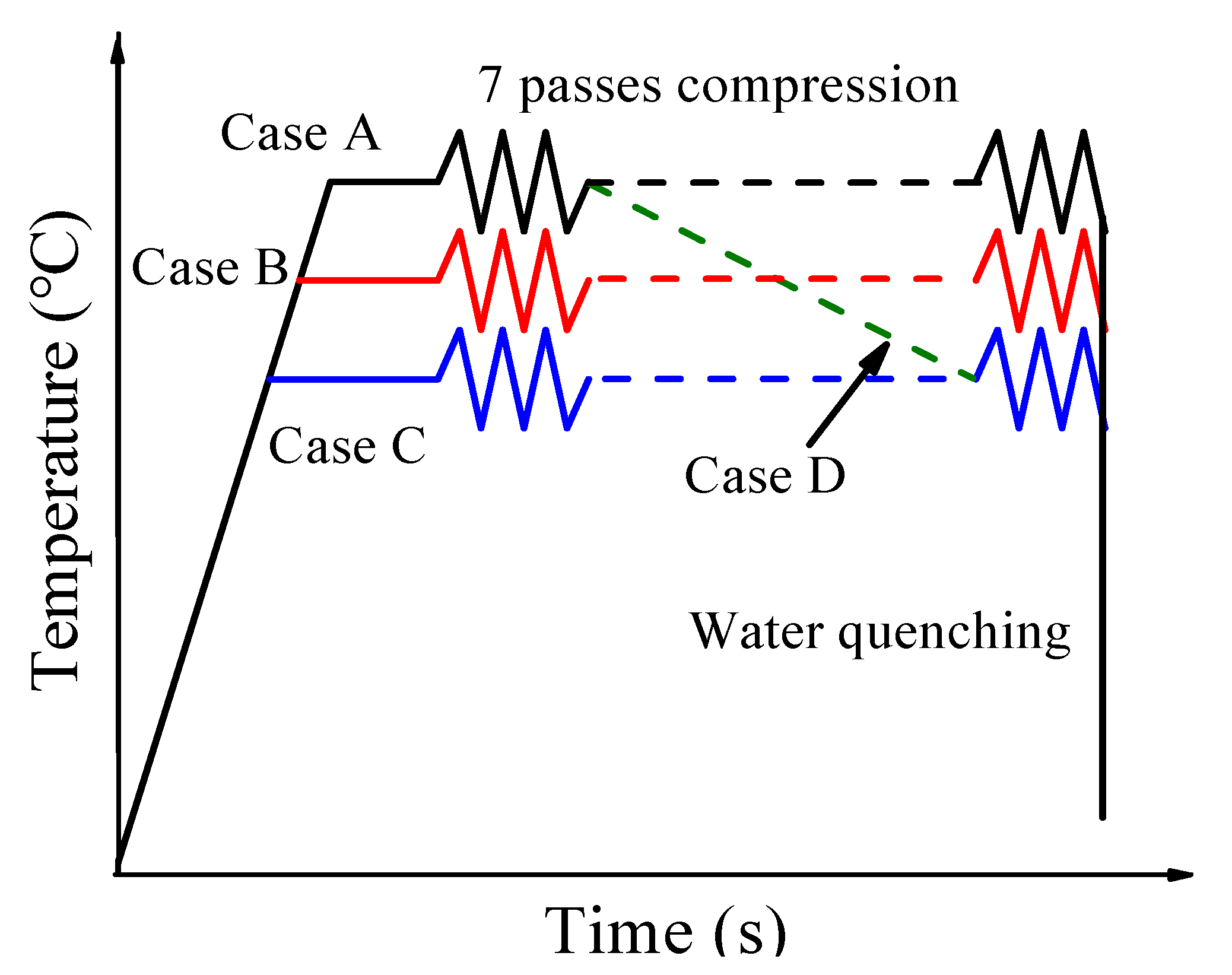
2. Experimental Procedures

The chemical composition of test steel was 0.46C–0.23Si–0.72Mn–0.03P–0.03S, all in wt %. The medium carbon steel was melted in a vacuum inductive furnace, and then cast into an ingot with diameter of 100 mm. The 10 kg ingot was homogenized at 1200 °C for 2 h to remove inhomogeneous microstructures evolved during solidification, and then forged into a square bar with a sectional area of 40 × 20 mm2 (total area reduction ε about 90%) in the temperature range of 1100–900 °C, and was cooled in air. The original microstructure was composed of ferrite and pearlite, with a size of ~20 μm. The size of specimens for plane strain deformation was 10 mm × 15 mm × 20 mm. The plane strain tests were conducted in a Gleeble-3500 (Dynamic Systems Inc., Austin, TX, USA). The schematic illustration of the compression testing machine is shown in Figure 1. The schematic diagram and strain path of tests is shown in Table 1 and Table 2, respectively. The test scheme is shown in Figure 2. For the rolling test, the specimens were heated up to the target temperature (700 °C) in a furnace and soaked for 20 min. The rolling tests were carried out on the φ350 mm × 350 mm reversible rolling mill. After the warm rolling process, one of specimens was put in furnace with 650 °C immediately, and cooled in furnace, while another one was cooled in water. The size of specimens for rolling tests was 23 mm × 45 mm × 100 mm. The rolling scheme is shown in Table 3 and Figure 3. Considering the laboratory physical conditions, the interval was set as 6 s, and the passes were reduced into 4 passes.
The microstructure was observed by scanning electron microscopy (SEM, Nova NanoSEM430, FEI, Boston, MA, USA), electron backscatter diffraction (EBSD, Oxford NORDLYS 2S, Oxford, UK), and transmission electron microscopy (TEM, Tecnai G2 F20, FEI, Boston, MA, USA). The fracture morphology was analyzed by SEM. The specimens for microstructure of SEM observation underwent mechanical polishing and erosion in 4% Nital. The orientation image was analyzed by EBSD technology. The samples of EBSD were mechanical polished, and subsequently electrolytic polished. The scan step was 0.15 μm. The low angle boundaries (LABs) are defined between 2° to 15°, and high angle boundaries (HABs) are above 15°. TEM samples were cut into 0.5 mm thickness and mechanical grinding down to about 30 μm, subsequently thinned to perforation by ion-beam milling. The tensile tests were carried out three times for each cooling mode on a universal testing machine (INSTRON-3380, INSTRON, Norwood, MA, USA) at a speed of 2 mm/min. The free gauge of tension samples is 2 × 4 × 50 mm3.

3. Results and Discussions

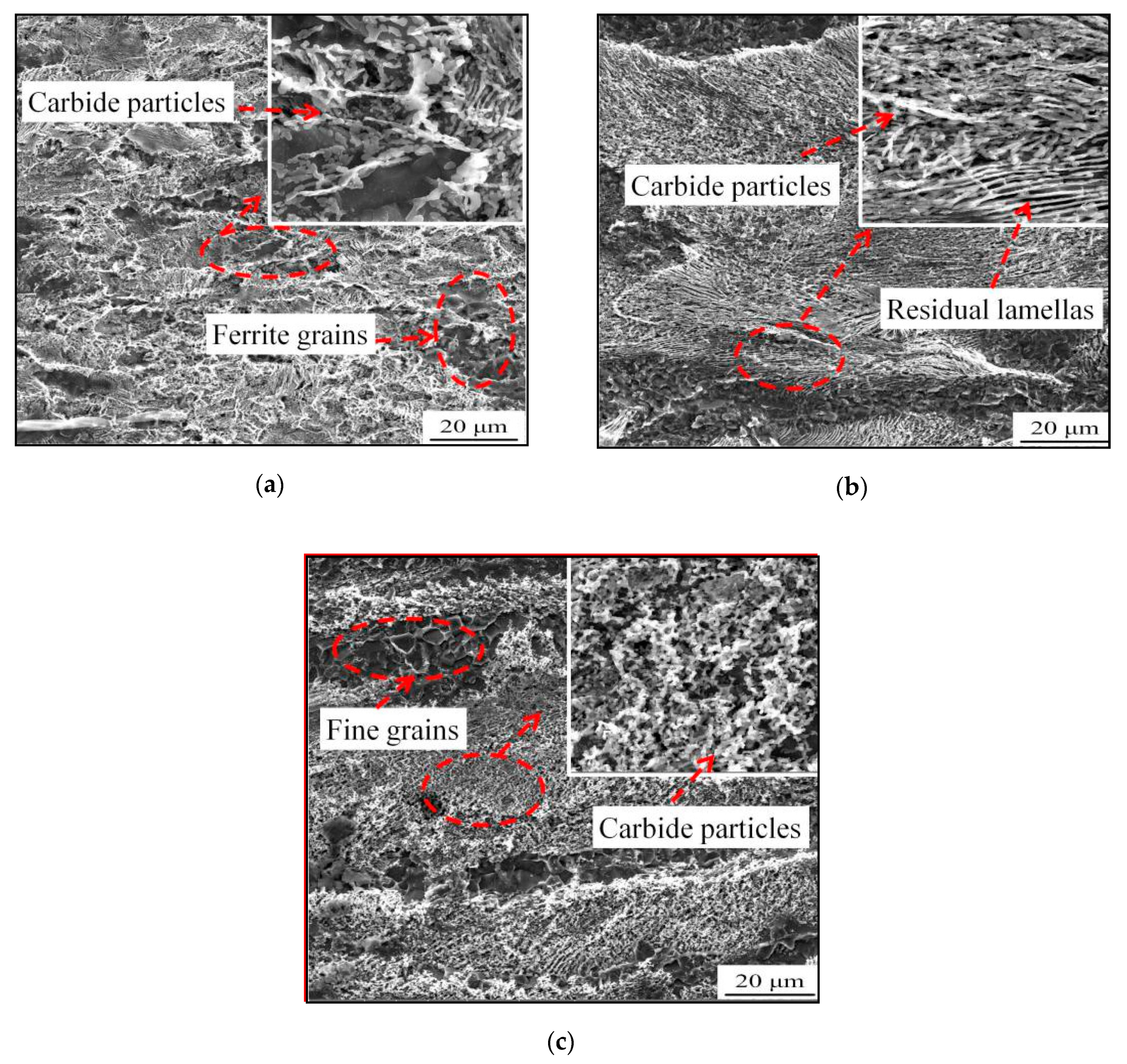
3.1. Effect of Temperature Scheme on Microstructure

The morphology of plane strain test of cases A–C is shown in Figure 4. At the temperature of 700 °C (case A), the energy of dislocation movement is strong. Hence, the dislocation density decreases rapidly. Dislocation annihilation and recovery occurs, and the subgrains form. The subgrains migrate to each other and absorb dislocations. This results in the increase of misorientation among subgrains. At last, the subgrains transform into normal grains rounded by HAGs [18]. Meanwhile, due to the high temperature, the stability of cementite lamellas decreases. Therefore, during the deformation, the cementite lamellas are fractured, kinked, and banked. The internal stress of lamellas promotes the cementite decomposition. Due to the strain distribution complexity of materials with different crystal structures, the softer materials bear more strain [19]. Hence, the dislocations fill into the interfaces of ferrite and cementite, due to the ferrite lower hardness. The carbon atoms decomposed from cementite diffuse by the dislocation channels to the low carbon regions. Hence, the dislocations promote cementite decomposition. However, there are some residual cementite lamellas in the pearlite colonies. This may be attributed to the initial orientation of cementite lamellas [20,21].
With the decreasing of temperature to 600 °C, the stability of cementite lamellas increases. However, some lamellas transform into carbon particles, which are arranged in the direction of initial lamellas, and there are more residual cementite lamellas and subgrains than that of case A.
By comparison of Figure 4a,b, it is obvious that the uniformity of microstructure of 700 °C is more than that of 600 °C. However, the grain size increases during deformation. Hence, it is necessary to anneal the specimens of 600 °C. However, the annealing process increases the cost and extends the process. Therefore, at the medium temperature, the microstructure variation has to be checked. Hence, there is not proper pearlite deformation at the temperature of 600 °C. This is consistent with the results of Ref. [22].
As shown in Figure 4c, there are lots of fine ferrite grains surrounded by HAGs, and the cementite lamellas transform into particles which align in the direction of initial lamellas. The uniformity and grain size of case C are better than that of other cases. Hence, it may be the best temperature for uniform microstructure and fine carbide particles. The fine grain coarsening is inhibited by the relative low temperature and the dispersed particles, and the driving force of dislocation gliding is sufficient for the absorbing of subgrain boundaries [23,24]. Therefore, the misorientation of subgrains increases, but the grain size remains unchanged. With the increasing strain, the fraction of fine ferrite grains transformed from subgrains increases. This results in the decrease of the average size of ferrite grains. It is obvious that the medium carbon steel is sensitive to deformation temperature.
The effect of temperature range on the ferrite evolution is shown in Figure 5. It is obvious that the grain size of case D is more homogeneous than that of case C, of which some ferrite grains reach submicron size. This indicates that the high temperature promotes the formation of uniform grains. In addition, the high temperature is beneficial to the decrease of rolling force.
Based on the above discussion and Figure 5, the proper temperature range may be 700–650 °C. To verify this, the microstructure of variable temperature compressions and laboratory rolling experiments are examined. The microstructures of case D are shown in Figure 6. The mean size of ferrite grains is about 1.2 μm. The fraction of submicron grains is about 60%. Along the line marked in Figure 5a, the curve of point-to-point misorientation fluctuates sharply, and some misorientation values exceed 15°, as shown in Figure 6c. This indicates that there are lots of boundaries of subgrains/grains in the initial pearlite regions. As illustrated in Figure 5a, the initial pearlite colonies are divided into several parts, which are subgrain regions and residual lamella regions. This may be attributed to the lamellas’ initial orientation.
During the compression process, some cementite lamellas transform into carbide particles. These particles play a role in pinning dislocations. With the increasing strain, the dislocation density increases near the particles [25], and the dislocations transform into the dislocation walls by dislocation accumulation near the particles. The dislocation walls absorbed the dislocations. At last, the subgrain boundaries formed [13,26]. Hence, there are lots of subgrain boundaries near the particles. The misorientation of subgrains boundaries increases. If the misorientation exceeds 15°, it may be recognized as a normal boundary. The initial pearlite regions are divided into several parts by the new formed boundaries. However, there are some residual lamellas in the initial pearlite regions. In the residual lamella regions, the dislocation variation is inhibited by the residual lamellas. The dislocations are filled in the spaces between the residual lamellas, as shown in Figure 7a, marked by arrows. Therefore, there are no subgrains in some initial pearlite regions.
The little size grains are transformed from the initial ferrite grains during the compression test. Due to the high stack energy of ferrite, the dislocation gliding is easier than that of austenite. Therefore, it is beneficial to the dislocation walls forming during the deformation, and the dislocations are absorbed quickly by the dislocation walls. At last, the subgrains trap dislocations and transform them into normal grains [27], as shown in Figure 6d. Another reason may be the reduced pinning effect of the carbide particles. By comparison with the initial pearlite colonies, the density of carbide particles is just a little, as shown in Figure 7b. Due to the similar conditions, the adjacent subgrains transform into the normal grains in almost the same way. Therefore, the fine ferrite grains block each other and remain. This results in the fraction of subgrain boundaries decreasing and the fraction of fine grains increasing.
During case D, there are some residual lamellas. However, the homogeneity is better than that of case C, and the grains are finer than that of case A. This means that the temperature range of 650–700 °C may be acceptable. However, the feasibility of production and the mechanical properties need to be tested. Therefore, the warm rolling experiments were carried out on the φ350 mm × 350 mm reversible rolling mill, and the comparison of mechanical properties was conducted.
The microstructure results of warm rolling tests are shown in Figure 8a,b. After the warm rolling test, some short residual lamellas remained in the initial pearlite regions. This is similar to the morphology of case D. However, the size of residual lamellas of warm rolling is longer than that of case D, which may be attributed to the deformation mode and intervals. By comparison of Figure 5a and Figure 8c, it can be concluded that the temperature range for warm rolling processes has a certain feasibility.

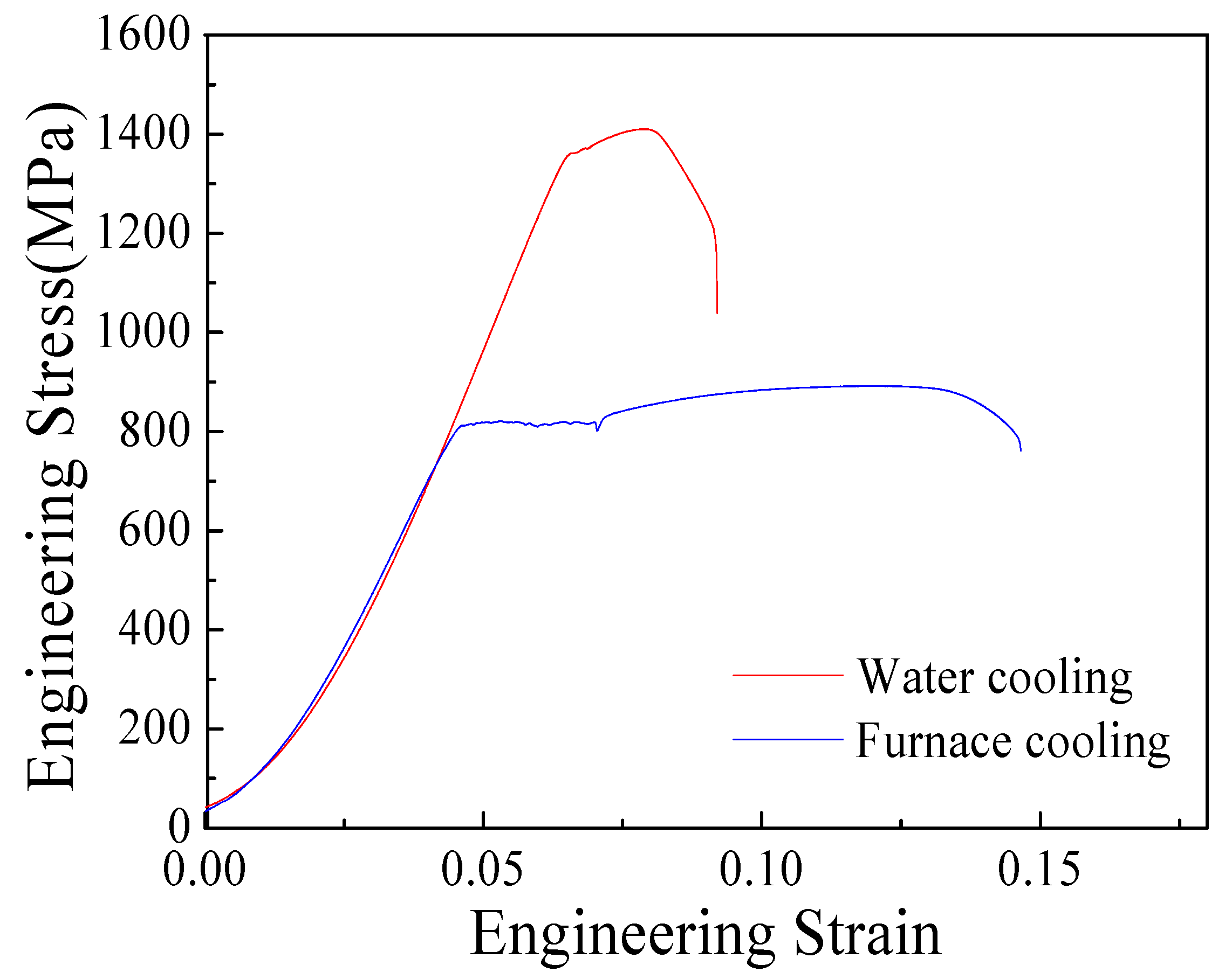
3.2. Effect of Cooling Mode on the Microstructure and Mechanical Properties

The effect of the cooling mode on the microstructure is shown in Figure 8. By comparison of furnace cooling and water cooling, the fraction of residual lamellas and subgrains decrease, after furnace cooling. The low cooling rate provides sufficient time for the residual lamella decomposition and subgrain boundaries absorbing dislocations. Therefore, the subgrains formed during rolling transform into normal grains by absorbing dislocations. Meanwhile, the residual lamellas decompose into iron and carbon atoms under the influence of lamellas’ inner stress and the high density dislocations and boundaries in adjacent ferrite matrix. The dislocations and boundaries play a role of channel for the carbon diffusion from the high carbon region into the low. With the cooling processing, the density of dislocations decreases. The carbon atom precipitates in the low carbon content regions in the form of particles, as shown in Figure 8b.
By comparison of Figure 8c,d, it is obvious that the fraction of subgrain boundaries decrease during furnace cooling, especially in the initial pearlite regions. The decrease of subgrain density in initial pearlite regions contributes the pearlite division. During the furnace cooling, the carbide particles decompose, and the pinning effect on dislocations disappears. Therefore, the subgrain boundaries’ misorientation can increase by absorbing the dislocations [23]. This results in the initial pearlite regions being divided by the boundaries with HABs. Meanwhile, some ultrafine ferrite grains grow. This results in the mean size increase.
The tensile tests are carried out three times for each cooling mode. The mechanical properties are shown in Table 4. One of the tensile curves for different cooling modes is shown in in Figure 9. The strength of water cooling is far higher than that of furnace cooling. It may be caused by the high density subgrain boundaries and dislocations in the matrix. Meanwhile, the high density defects result in poor ductility. During water cooling, there is not enough time for dislocations’ annihilation and recovery. The high density defects caused by rolling decrease the dislocations’ interaction and the space of dislocation accumulation [11] during the tensile test. Therefore, the ductility is poorer than that of furnace cooling. The combination of strength and ductility after furnace cooling is better than that of water cooling. The low density defects promote the interaction among dislocations and particles. Meanwhile, the low density dislocations provide a large space for dislocation accumulation. Therefore, the specimens after furnace cooling possess better ductility. In addition, the precipitated carbide particles pin the dislocation and increase the dislocation gliding resistance. Meanwhile, the pinning effect increases the dislocation density during the tensile test. This contributes to the high strain hardening rate and uniform elongation [10].
The yield strength of furnace cooling is about 826 MPa, and the ductility is about 14.7%. The strength and ductility of C–Mn steel with 0.3% C after a 2 h annealing process is about 560 MPa and 20%, respectively [10]. Torizuka et al. [26] compressed the 45 steel at the temperature range of 600–500 °C with a multi-direction strain of 3.0, and the strength and ductility was about 16% and 910 MPa, respectively. The mechanical properties in this research seem to be slightly less than the results of Ref. [10,26]. This may be attributed to the small strain and less homogeneous microstructure. Another side may be the test conditions; the gage length of Ref. [10,26] is about 25 mm, while it is 50 mm in this paper. The real properties of furnace cooling may not be less than the reports. Although the best cooling scheme needs to be further researched for better properties, this indicates that the temperature scheme (temperature range for warm rolling and furnace cooling) may be a feasible way for medium carbon steel warm rolling.
The fracture morphologies of two cooling modes are shown in Figure 10a,b. The size and depth of the dimples of furnace cooling fracture are larger and deeper than that of water cooling. Generally, the relationship between ductility and size of dimples is a positive correlation. The large and deep dimples promote the phenomenon that the direction of crack propagation varies along the dimples’ surface. This increases the cracks’ propagation path. Therefore, it needs more energy to overcome the resistance than that of a smooth surface [28]. This means that the furnace cooling process has higher ductility than that of water cooling. The result is consistent with the tensile test.

4. Conclusions

The effect of temperature scheme on the microstructure and properties during WD is investigated; the main conclusions are as follows:
(1) The influence of processing temperature on the microstructure variation is considerable. At the temperature of 650 °C, the microstructure is fine and homogeneous, and the size of some ferrite grains reaches sub-micrometer scale.
(2) At the temperature range of 650–700 °C, the microstructure is fine and homogeneous. Most lamellas transform into carbide particles, and the initial pearlite regions are divided into several parts. The size of ferrite grains decreases, due to misorientation increases. However, there are lots of subgrains in the matrix. The average grain size is coarser than that prepared by the thermal simulator Gleeble-3500. This may be caused by the deformation conditions.
(3) The mechanical properties indicate that a low cooling rate is necessary for the better combination of strength and ductility, and the low cooling rate provides more time for recovery and distorted cementite dissolution. With the dislocation density decreasing, some carbide particles precipitate in the fine ferrite matrix, and the strength decreases and the ductility increases. The fracture of furnace cooling shows the distinguishing feature of ductile fracture.

Author Contributions

Conceptualization, H.-B.L. and L.F.; Methodology, L.F.; Validation, L.-S.C. and L.F.; Formal Analysis, L.F. and L.-S.C.; Investigation, H.-B.L.; Resources, L.-S.C.; Data Curation, H.-B.L.; Writing—Original Draft, H.-B.L. Preparation, H.-B.L.; Writing—Review & Editing, L.F. and L.-S.C.; Supervision, L.F.

Funding

This work was supported by Hebei province natural science funds (E2015209243, E2017209048, E2017209121), Hebei province department of science and technology (16211036), National Natural Science Foundation of China (51574107, 51474091), and the High performance metal and composite materials science and technology innovation team of Tangshan (15130202C).

Conflicts of Interest

The authors declare no conflict of interest.

References

  1. Zhao, L.J.; Park, N.; Tian, Y.Z.; Shibata, A. Dynamic transformation mechanism for producing ultrafine grained steels. Adv. Eng. Mater. 2018, 20. [Google Scholar] [CrossRef]
  2. Shen, X.J.; Tang, S.; Wu, Y.J.; Yang, X.L.; Chen, J.; Liu, Z.Y.; Misra, R.D.K.; Wang, G.D. Evolution of microstructure and crystallographic texture of microalloyed steel during warm rolling in dual phase region and their influence on mechanical properties. Mater. Sci. Eng. A 2017, 685, 194–204. [Google Scholar] [CrossRef]
  3. Hu, X.Y.; Zhao, H.L.; Song, N.; Song, M. Grain refinement and phase transition of commercial pure zirconium processed by cold rolling. Mater. Charact. 2017, 129, 149–155. [Google Scholar] [CrossRef]
  4. Zhao, H.L.; Song, M.; Ni, S.; Shao, S.; Wang, J.; Liao, X.Z. Atomic-scale understanding of stress-induced phase transformation in cold-rolled Hf. Acta Mater. 2017, 131, 271–279. [Google Scholar] [CrossRef]
  5. Han, H.N.; Suh, D.W. A model for transformation plasticity during bainite transformation of steel under external stress. Acta Mater. 2003, 51, 4907–4917. [Google Scholar] [CrossRef]
  6. Okitsu, Y.; Takata, N.; Tsuji, N. Analysis of the tensile behavior of a TWIP steel based on the texture and microstructure evolutions. Scr. Mater. 2009, 60, 76–79. [Google Scholar] [CrossRef]
  7. Li, B.; Liu, Q.Y.; Jia, S.J.; Ren, Y.; Wang, B. Fabricating ultrafine grain by advanced thermomechanical processing on low-carbon microalloyed steel. Scr. Mater. 2018, 152, 132–136. [Google Scholar] [CrossRef]
  8. Ning, J.L.; Feng, Y.L.; Wang, M.M.; Zheng, S.B.; Li, J. Dependence of tensile properties on microstructural features of bimodal-sized ferrite/cementite steels. J. Iron Steel Res. Int. 2017, 24, 67–76. [Google Scholar] [CrossRef]
  9. Tsai, S.P.; Tsai, Y.T.; Chen, Y.W.; Yang, J.R.; Chen, C.Y.; Wang, Y.T.; Huang, C.Y. Precipitation behavior in bimodal ferrite grains in a low carbon Ti-V-bearing steel. Scr. Mater. 2018, 143, 103–107. [Google Scholar] [CrossRef]
  10. Song, R.; Ponge, D.; Raabe, D. Improvement of the work hardening rate of ultra-fine grained steels through second phase particles. Scr. Mater. 2005, 52, 1075–1080. [Google Scholar] [CrossRef]
  11. Zhao, M.C.; Hanamura, T.; Qiu, H.; Nagai, K.; Yang, K. Grain growth and Hall-Petch relation in dual-sized ferrite/cementite steel with nano-sized cementite particles in a heterogeneous and dense distribution. Scr. Mater. 2006, 54, 1193–1197. [Google Scholar] [CrossRef]
  12. Wang, T.S.; Li, Z.; Zhang, B.; Zhang, X.J.; Deng, J.M.; Zhang, F.C. High tensile ductility and high strength in ultrafine-grained low-carbon steel. Mater. Sci. Eng. A 2010, 527, 2798–2801. [Google Scholar] [CrossRef]
  13. Storojeva, L.; Ponge, D.; Kaspar, R.; Raabe, D. Development of microstructure and texture of medium carbon steel during heavy warm deformation. Acta Mater. 2004, 52, 2209–2220. [Google Scholar] [CrossRef] [Green Version]
  14. Okitsu, Y.; Takata, N.; Tsuji, N. Dynamic deformation behavior of ultrafine-grained iron produced by ultrahigh strain deformation and annealing. Scr. Mater. 2011, 642, 896–899. [Google Scholar] [CrossRef]
  15. Torizuka, S.; Ohmori, A.; Murty, S.V.S.N.; Nagai, K. Effect of strain on the microstructure and mechanical properties of multi-pass warm caliber rolled low carbon steel. Scr. Mater. 2006, 54, 563–568. [Google Scholar] [CrossRef]
  16. Murty, S.V.S.N.; Torizuka, S.; Nagai, K. Microstructural evolution during simple heavy warm compression of a low carbon steel: Development of a processing map. Mater. Sci. Eng. A 2005, 410–411, 319–323. [Google Scholar] [CrossRef]
  17. Song, R.; Ponge, D.; Raabe, D.; Kaspar, R. Microstructure and crystallographic texture of an ultra-fine grained C-Mn steel and their evolution during warm deformation and annealing. Acta Mater. 2005, 53, 548–558. [Google Scholar] [CrossRef]
  18. Miyamato, G.; Karube, Y.; Furuhara, T. Formation of grain boundary ferrite in eutectoid and hypereutectoid pearlitic steels. Acta Mater. 2016, 103, 370–381. [Google Scholar] [CrossRef]
  19. Mungole, T.; Mansoor, B.; Ayoub, G.; Field, D.P. Bifurcation in deformation behavior of Cu and Ta by accumulative roll-bonding at high temperature. Scr. Mater. 2017, 136, 87–91. [Google Scholar] [CrossRef]
  20. Prasad, C.; Bhuyan, P.; Kaithwas, C.; Saha, R.; Mandal, S. Microstructure engineering by dispersing nano-spheroid cementite in ultra-fine grained ferrite and its implications on strength-ductility relationship in high carbon steel. Mater. Des. 2018, 139, 324–335. [Google Scholar] [CrossRef]
  21. Rastegari, H.; Kermanpur, A.; Najafizadeh, A.; Somani, M.C.; Porter, D.A.; Ghassemali, E.; Jarfors, A.E.W. Determination of processing maps for the warm working of vanadium microalloyed eutectoid steels. Mater. Sci. Eng. A 2016, 658, 167–175. [Google Scholar] [CrossRef]
  22. Rastegari, H.; Kermanpur, A.; Najafizadeh, A.; Porter, D.; Somani, M. Warm deformation processing maps for the plain eutectoid steels. J. Alloy. Compd. 2015, 626, 136–144. [Google Scholar] [CrossRef]
  23. Eghbali, B. EBSD study on the formation of fine ferrite grains in plain carbon steel during warm deformation. Mater. Lett. 2007, 61, 4006–4010. [Google Scholar] [CrossRef]
  24. Liang, J.H.; Zhao, Z.Z.; Zhang, C.H.; Tang, D.; Yang, S.F.; Liu, W.N. Microstructure evolution and mechanical properties influenced by austenitizing temperature in aluminum-alloyed TRIP-aided steel. J. Iron Steel Res. Int. 2017, 24, 1115–1124. [Google Scholar] [CrossRef]
  25. Ohmori, A.; Torizuka, S.; Nagai, K. Strain-hardening due to dispersed cementite for low carbon ultra-fine grained steels. ISIJ Int. 2002, 44, 1063–1071. [Google Scholar] [CrossRef]
  26. Torizuka, S.; Muramatsu, E.; Murty, S.V.S.N.; Nagai, K. Microstructure evolution and strength-reduction in area balance of ultrafine-grained steels processed by warm caliber rolling. Scr. Mater. 2006, 55, 751–754. [Google Scholar] [CrossRef]
  27. Xu, D.M.; Li, G.Q.; Wan, X.L.; Misra, R.D.K.; Zhang, X.G.; Xu, G.; Wu, K.M. The effect of annealing on the microstructural evolution and mechanical properties in phase reversed 316LN austenitic stainless steel. Mater. Sci. Eng. A 2018, 720, 36–48. [Google Scholar] [CrossRef]
  28. Liu, B.X.; Wei, J.Y.; Yang, M.X.; Yin, F.X.; Xu, K.C. Effect of heat treatment on the mechanical properties of copper clad steel plates. Vacuum 2018, 154, 250–258. [Google Scholar] [CrossRef]
Figure 1. Schematic illustration of plane strain test machine. (a) Compression equipment and (b) description of main parts in detail (unit: mm).
Metals 09 00077 g001
Figure 2. Test scheme of plain strain compression.
Metals 09 00077 g002
Figure 3. Scheme of rolling test.
Metals 09 00077 g003
Figure 4. Microstructure of case A, B, C: (a) case A, (b) case B, and (c) case C.
Metals 09 00077 g004
Figure 5. Boundary map comparison between case D (a) and case C (b).
Metals 09 00077 g005
Figure 6. Grain situation of testing scheme D: (a) Misorientation distribution; (b) Grain size distribution; (c) Misorientation distributed along the line marked in Figure 4a; (d) Microstructure.
Metals 09 00077 g006aMetals 09 00077 g006b
Figure 7. TEM microstructure: (a) Residual cementite lamellas; (b) Particles distributed in ferrite boundaries.
Metals 09 00077 g007
Figure 8. Microstructure and boundaries map of different cooling modes: (a,c) Water cooling; (b,d) Furnace cooling.
Metals 09 00077 g008
Figure 9. Tensile curves of different cooling modes.
Metals 09 00077 g009
Figure 10. Comparison of fracture appearance between furnace and air cooling: (a) Water cooling; (b) Furnace cooling.
Metals 09 00077 g010
Table 1. Temperature of passes for different cases.
Passes1234567
Case
A700700700700700700700
B600600600600600600600
C650650650650650650650
D700689679670663655650
Table 2. Strain path of plane stain compression.
PassStrainStrain Rate (s−1)Intervals (s)
10.3314.225.01
20.4317.913.76
30.4420.812.63
40.4123.541.82
50.3927.661.23
60.223.660.89
70.120.68--
Table 3. Rolling test strain path.
PassReal StrainReduction (mm)Strain RateInterval (s)
10.438.0014.226.00
20.638.0017.916.00
30.634.0020.816.00
40.632.0023.54--
Table 4. Tensile mechanical properties.
Cooling ModesYield Stress (MPa)Ultimate Stress (MPa)Uniform Elongation (%)Total Elongation (%)
Furnace cooling850.18 ± 10.62964.81 ± 13.2111.63 ± 3.6116.52 ± 4.52
Water cooling1202.44 ± 8.621409.73 ± 10.528.72 ± 2.2210.05 ± 3.01

