Article

A Comprehensive Study on the Deformation Behavior of Hadfield Steel Sheets Subjected to the Drop Weight Test: Experimental Study and Finite Element Modeling

1
Department of Mechanical Engineering, Uşak University, 64200 Uşak, Turkey
2
Mechanical and Manufacturing Engineering School, Supmeca-Paris, 93407 Saint Ouen, France
3
UNICAMP/FEM-Department of Materials, University of Campinas, Campinas/SP 13083-860, Brazil
*
Authors to whom correspondence should be addressed.
Metals 2018, 8(9), 734; https://doi.org/10.3390/met8090734
Submission received: 8 August 2018 / Revised: 4 September 2018 / Accepted: 4 September 2018 / Published: 18 September 2018

Abstract

:
This work presents the results of experimental and finite element modeling studies of impact behavior on the response of a high content of manganese steel blanks with a 1.2 mm thickness of sheets, known also commercially as Hadfield steel (an austenitic structure with a basic composition containing C 1.2% and Mn 12%). The study was done with a standard drop weight test device under certain variable parameters (velocity: 3 m/s and 5 m/s and temperature: room temperature, 70 °C, 100 °C, and 140 °C). In this study, the evolution of force and energy values were analyzed depending on the time in the case of impact. Special care was given to the evolution of peak stress counters of finite element simulation for different temperatures. The results of the force-time, energy-time, and force-displacement curves under different temperatures and impact velocities are compared experimentally and numerically. Then the discussion are built on the effect of the operational parameters on the damage behavior of this steel. Both of these works (experimental and finite element modeling) were compared and highly satisfying results were obtained.

1. Introduction

Hadfield steel sheets, being extremely tough and at the same time very sensitive to plastic deformation, are mainly used in various types of military applications [1]. All of the unique mechanical properties such as high strength, high toughness, abrasion, and heavy impact resistance show up together. The mechanical properties of the Hadfield steel vary according to the amount of carbon and manganese components. At approximately 1.2% C, tensile strength and ductility reach maximum values, and as carbon content increases, these properties tend to decrease continuously. Hardens are happened very rapidly as a function of the plastic deformation range [2,3]. The yield stress of this steel does not show any singular point on the stress-strain curve because of the stacking fault appearing in the grains just after elastic domain. The stacking faults can take position in the direction of the stress and thicken during deformation and can easily be transformed into twins. Finally, they play an effective role in the deformation mechanism, mainly caused by work hardening of the structure. For this reason, the stress-strain curve of Hadfield steel shows a serrated flow caused by dynamic strain-aging during the deformation process (twinning and de-twinning), successfully repeated during the deformation. A number of former research studies [4,5,6,7,8,9,10,11,12,13] described the work hardening behavior and certain ideas were proposed to explain this phenomenon in the steel during the forming processes; for example, the usual tensile tests and deep drawing of thin sheets of Hadfield steel are typical examples where the effect of the deformation rate on the work hardening mechanism can be observed. In addition, there are detailed studies in the literature, investigating the effects of internal structure interactions and phase transformations on plastic deformation mechanisms formed under different loads of hybrid materials produced with the desired properties in terms of engineering [14,15,16].
It has also been shown in the results of former studies that it is only an austenitic diffraction peak [2,8,9,10,11,12,13]. In these specimens, which are in conformity with previous studies, there is no evidence that transformation from the austenite structure (γ) to the α or ε martensite structure is observed by the induced strain [17,18,19,20,21,22,23]. For this reason, it can be seen that the work hardening mechanism is not the martensite hardening theory [24].
Another typical example is the impact damage to observe work hardening phenomenon and damage behavior during the impact caused by drop weight testing carried out on the of Hadfield steel sheets. This is important for military applications of Hadfield steel sheets which are used in the manufacture of special helmets and security armor lining-plates. Many different types of protection (for example for some of the military helicopters) need to be produced to withstand projectiles with a low impact rate. It is rather difficult to understand the deformation behavior of this steel in army ballistic testing. In fact, for ballistic testing of materials for military applications, several different test types and characterization techniques are used. Among them, drop-weight testing (DWT) is a quite simple method. Up to now, a considerable number of works has been carried out for different application of Hadfield steel sheets. Details of formability–deformation behavior of Hadfield steel (1.2% C and 12% Mn) and also other experimental procedures have already been explained in other references [2,9,10,18].
This study aims to discuss the effect of operational parameters on damage behavior in impacted Hadfield steel sheets and also to compare the results obtained of the experimental and numerical studies. The experimental and numerical results obtained within the scope of this study are then further compared with the related studies in the literature [1]. Another aspect of this article is to present the test engineer with a useful user manual which is a powerful tool for using measurement parameters, obtained during impact testing, to compute the related impact, absorbed, and elastic energies. The rapid work hardening mechanism in Hadfield steel at various temperatures and strain rates (different impact velocity levels) can be understood very well as well as made clearer by means of drop weight testing [2].

2. Experimental Method and Physical Conditions

Test specimens were prepared of 100 mm × 100 mm × 1.2 mm dimensions from high manganese steel blanks according to the drop weight impact test conditions. The CEAST 9350 drop weight impact test machine (Instron, Norwood, MA, USA) was used to analyze the deformation and damage behavior of Hadfield steel sheets and to characterize the impact velocity test. Figure 1 illustrates that the base of the machine is engineered as an environmental chamber as well as a pneumatic clamping device [25]. Drop weight impact tests were carried out with according to the standard of ASTM D5628 FE [26].
All of the impact tests were performed at two different impact velocities (crosshead velocity) of 3 and 5 m/s, and four different test temperatures as room temperature, 70, 100, and 140 °C, respectively. To prevent slippage during the impact test and to keep the test specimens in a rigid position, pressure is applied by these two blank holders onto steel sheet specimens (100 mm × 100 mm) placed between two steel blank holders as opposing supports containing a 40 mm circular hole. At the top component of the test machine, the mass of the dropping equipment containing the weight box to add mass and the striker is about 10.3 kg. The striker is composed of a rod connected with impactor nose and force transducer. During the impact test, the measurement of the contact load between the specimens of the steel plate and the impact nose is carried out with a force transducer depending on the time using Visual-IMPACT Software (Version 6.00, Instron, Norwood, MA, USA) based on Newton’s second law, kinematic transformed time-force histories taken from the force transducer to the velocity, and displacement histories [26].
The outside of the damaged samples (on the top of the dome) were also investigated with Scanning Electron Microscopy (SEM; JEOL USA, Inc., Peabody, MA, USA). The effect of the applied force is evaluated by the impact damage of the Hadfield steel sheets that refers to the ability to allow a specified amount of damage [9,13,21,22,23,24].

3. Numerical Method and Modeling Conditions

Numerical models are powerful auxiliary tools that can help in the structural modeling and optimal functional design process of energy absorbing materials. Although there have been significant developments in the modeling of damage and failure processes as a result of impact, penetration and destruction in the past few years, there are still many challenges that need to be overcome. Numerical modeling can be used as a powerful tool to predict the physical-chemical-mechanical behavior of developed new materials under different loading conditions. In addition, it can be used as an aid in evaluating the optimal functionality of the structures and the most suitable material according to the needs of the design. The optimum design area of the energy absorbing materials should be evaluated in detail but there is a gap which is still in its early stage [27]. For this reason, much more attention is paid to finite element analysis to predict the deformation behavior after damage of the Hadfield steel sheets.
In this study, the modeling of low velocity impact behavior on high manganese steel plates of 100 mm × 100 mm × 1.2 mm in size is performed by the use of commercial software Abaqus®/Explicit (2018, Dassault Systèmes, Waltham, MA, USA). The damage of high manganese steel modeling is made with VUMAT (Abaqus®/Explicit workspace compatible with the User MATerial) subroutine. Numerical simulations were made according to the experimental conditions that are in the configuration consisting of four different temperatures: 23, 70, 100, and 140 °C and two different velocities; 3 and 5 m/s. A contact period is defined between Impactor and steel plate as appropriate for the general contact properties. After that, Abaqus®/Explicit software is automatically created with a contact pair and each time a contact is defined for each solution step by step in the simulation. Finally, energy vs. time and force vs. time graphics were obtained from numerical analysis. Consequently, very good agreements are obtained between the experimental and numerical simulations based with the model created in the present work.

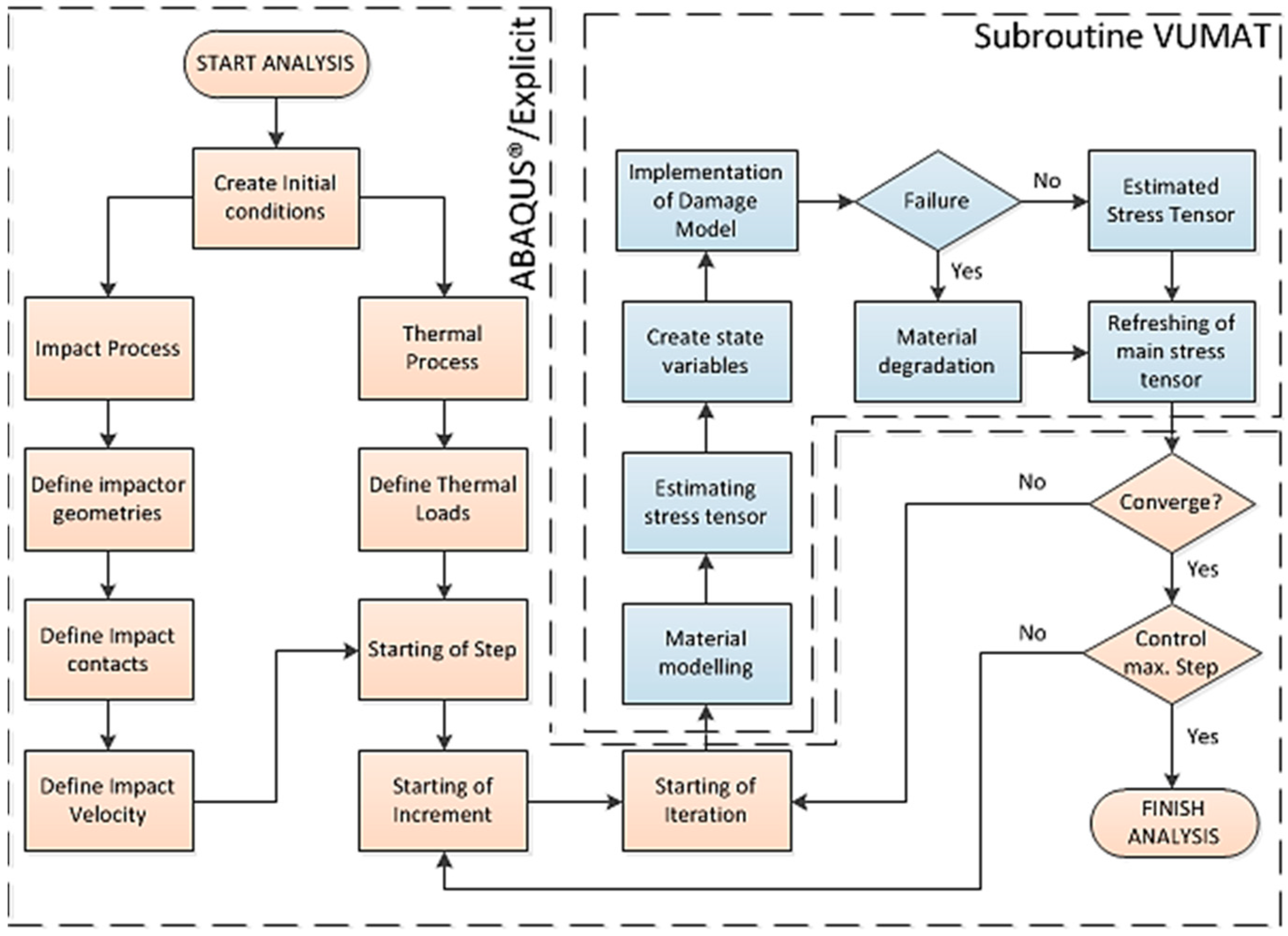
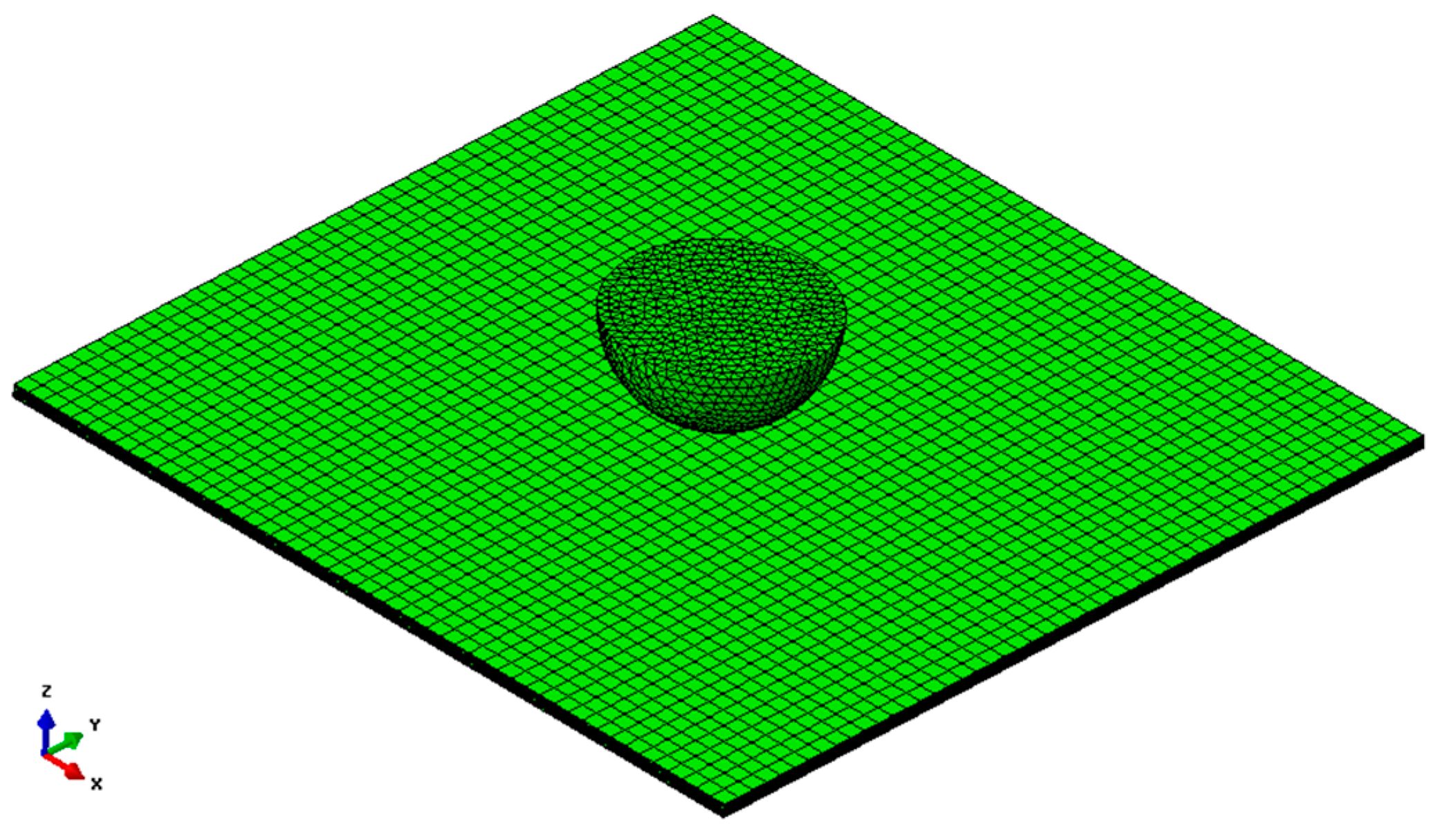
3.1. Methodology Used for Modeling

Experimental conditions are modeled using the Finite Element Method (FEM). Abaqus®/Explicit workspace was used by implementing a VUMAT subroutine in it for modeling of the materials. In fact, the explicit solution technique is a very suitable procedure for determining the metal damage of the subsequent dynamic impact load. The explicit dynamic analysis procedure in Abaqus®/Explicit is based upon the implementation together with the integration rules of the diagonal elements or lumped mass matrix. As indicated in Equations (1) and (2), explicit difference integration rules are used between impactor and steel plate such as integrated motion equations [28].
u ˙ ( i + 1 2 ) = u ˙ ( i 1 2 ) + Δ t ( i + 1 ) + Δ t ( i ) 2 u ¨ ( i )
u ( i + 1 ) = u i + Δ t ( i + 1 ) u ˙ ( i + 1 2 )
where u ˙ is velocity and u ¨ is acceleration respectively. The superscript (i) refers to the increment number and i 1 2 and i + 1 2 refer to mid increment values and the central difference integration operator is u ˙ ( i 1 2 ) and u ¨ ( i ) is from the previous increment.
The algorithmic chart of the whole process is illustrated in Figure 2. First of all, temperature and impact conditions in the experiments are created numerically. Then the high manganese steel plate and impactor geometry is modeled. The boundary conditions, well-defined for the steel plate and low velocity parameters are also defined for the impactor. Damage initiation on the metal plate is examined by the modeling of impactor and high manganese steel plate materials via the VUMAT subroutine.
Stress tensor components are purchased in the metal damage model for the numerical simulation. It means that a stress tensor for each integration point is obtained individually by the VUMAT subroutine. For example, if metal plasticity damage does not start, the updated stress tensor should be equal to the original stress tensor. Then, each simulated situation is recorded to compare with the increase in each step. In this way, the incremental loop is continuous until the stress level reaches the appropriate value for each step to create impact damage.
Figure 3 illustrates that the meshed view of the finite element model of high manganese steel plate is modeled by using eight node brick (C3D8R: Eight-node brick element with reduced integration) as linear elements and a semi-spherical impactor with a diameter of 20 mm is defined as four node (R3D4: 3D bilinear discrete rigid quadrilateral) elements [29].
The conditions determined in the experimental studies are also used in numeric model studies. In this study, the Rice-Tracey model is preferred in the modeling of high manganese Hadfield steel in which the behavior under low velocities is investigated in detail. This model is the most appropriate analytical model that can characterize the micro- and macro-structure changes under the effect of impact generated at physically different temperatures and at different velocities. Within the scope of this study, the use of this model was achieved through the finite element method. This analytical model used in the study can calculate the stages of damage occurring on the basis of the stresses on the material and the continuous increase of these stresses. For this, it primarily involves isotropic hardening, which causes elastic-plastic deformation due to stresses on the material. After, these stresses can then progressively demonstrate the irreversible damage that occurs after the material has exceeded its strength limits. With regard to this model used in the study, more detailed explanations are given in the next Section 3.2. After that this suitable model for high manganese steel material is implemented as a FORTRAN® software (2018, Intel Composer XE, NY, USA) subroutine for using in the finite element code. For the model, VUMAT subroutine is implemented into Abaqus®/Explicit software.

3.2. Damage Mechanism of High Manganese Steel

Operational parameters accomplished in the VUMAT subroutine are illustrated in Figure 2. The flow diagram systematically shows the relationships between the steps of the numeric model through the finite element method. The most important factors that ensure this flow chart are original are that the accuracy and reduced working time of the parameters used in the construction of the numerical model according to the data obtained from the test results are determined/converged and the damage geometry is formed during the obtained stages. Therefore, it is another advantages that help us to understand the associations of the physical parameters with each other for the next different dimension studies in the framework of the obtained parameters of the model. In this figure, the theoretical background of damage modeling of the material is well-described. The damage modeling of material carried out by means of analytic equations with FORTRAN® software is inserted in Abaqus®/Explicit.

3.2.1. Rice-Tracey Model

This model is chosen because equivalent plastic strain of the initial damage should be considered as a function of the velocity change of triaxial stress and strain. Here, there are two major mechanisms of ductile metal damage: Ductile fracture due to nucleation, growth, and progression and also shear fracture due to the local shear band.
Stress triaxility is frequently used as a parameter to define multi-axiality in the stress state that is given such that:
σ ˜ = σ m σ ¯ = p / σ ¯
where σ m mean stress or hydrostatic pressure and the von Mises equivalent stress, σ ¯ . In fact, Rice and Tracey [30] were considered based on the ductile void enlargement under triaxial stress, σ ˜ as an important parameter in the model for determining during the damage initiation mechanism. This parameter is important and based on the effect of damage initiation of the two major mechanisms mentioned above for the damage mechanism [31].
0 ε ¯ f exp ( 3 2 σ ˜ ) d ε ¯ = C RT
where, ε ¯ f refers to plastic strain change during the breaking of the material. Also, isotropic hardening is identified in elastic-plastic damage initiation that consists of two types of elasticity: softening of the yield stress and degradation of elasticity. As a result of the speed and acceleration values calculated from the functions in Equations (1) and (2), there are deformations due to different stresses on the test specimen, and a damage mechanism that occurs due to these deformations. In order to calculate these mathematically, it is first necessary to determine the mechanical behavior of the material in question on the micro- and macro-scale. The Rice-Tracey model based on the stress triaxility value given in Equations (3) and (4) expresses the damage mechanism of the material examined in the research in terms of calculated coefficients. However, in order to determine the occurrence of elastic-plastic damage on the material, it is necessary to determine the distribution of stress on the material and determine the formation stages. As is known from experimental studies, the final damaged specimens are obtained at the end of the experiment. The investigation of the effects of these is done in connection with the results. For the reason, that stress distribution on the material directly affects the occurrence of damage, in the scope of the study, first the damage mechanism is examined in Section 3.2.1, followed by formation of the stresses that are caused in Section 3.2.2. The material modeling is then created by using isotropic hardening in terms of a comprehensive study.

3.2.2. Isotropic Hardening

As a result of low velocity impact in the high manganese steel plate stress distribution occurs homogenously in all directions, only yield surface is change. For this reason, isotropic hardening model is used. It means that isotropic hardening model in Abaqus®/Explicit is used for all numerical analysis along to the change in each plastic strain in the steel plate as identified in Equation (5). Therefore, isotropic hardening should be enlarged up to the initial yield surface f(σ) = 0 isotropically. In addition, the stress value generated during analytically stress-induced damage modeling is similar to the von Mises equivalent stress ( σ ¯ σ ).
f ( σ ) κ ( α ) = 0
where “ κ ” is a monotonically increasing function of the hardening parameter “α”.
This hardening parameter can be described as the effective plastic strain or strain-hardening hypothesis “α = ε ¯ p ” and the total plastic work “α = Wp” are explained here as the work-hardening hypothesis [13,21,22,23,24,32,33].

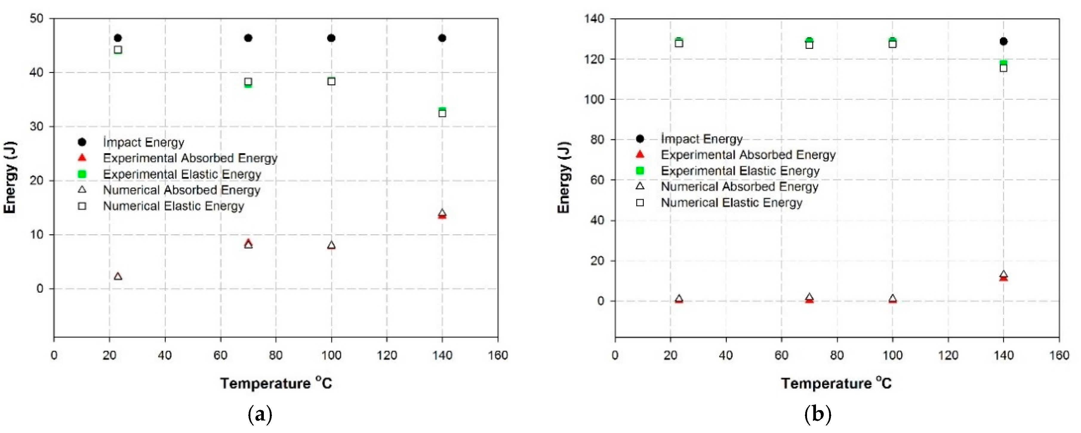
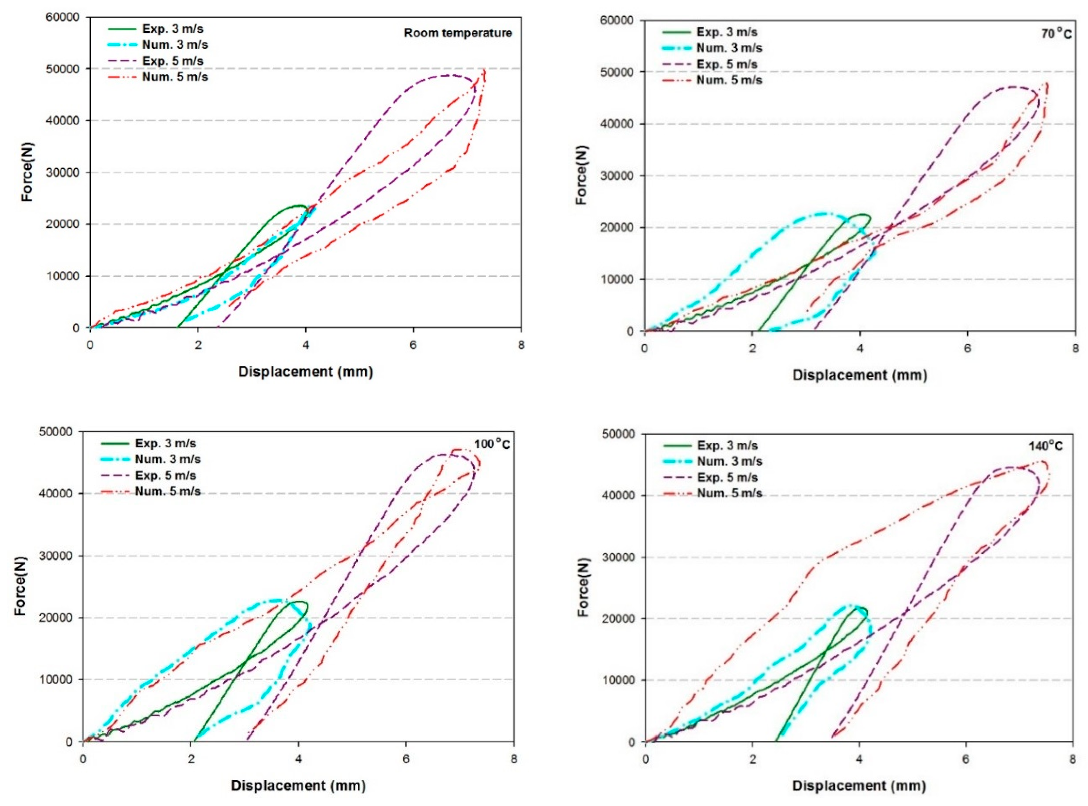
4. Results and Discussion

First discussion is given on the impact test results shown as force-time, energy-time and force-displacement graphics. All of the experimental and numerical impact results are compared depending on the temperature (variable from ambient up to 140 °C) and impact velocity (3 and 5 m/s). After that, evolution of impact, absorbed, and elastic energies are compared as a function of temperature and impact velocity for each experimental and FEM result. Second, discussion is given on the damage mechanisms of Hadfield manganese steel at high impact velocities depending on the time (deformation behavior and spring back effect of the high manganese steel sheets subjected to impact damage). After that, a detailed comparison is shown between numerical and experimental damage shapes for different temperatures; isotropic strain waves are evaluated as a typical deformation characteristic of high manganese steel sheets according to the model created on the high manganese steel sheets.
Figure 4 and Figure 5 show the evolution of the force and energy depending on time. Both of two curves consider two impact velocities under different temperature conditions. At the beginning of the curves, there is a small part of the curve called incubation time (t < 0.5 ms) coming from the initial contact between steel plate and punch. From this point, a linear increment begins (steady state) for all of the curves that indicates uniform deformation on the specimen during the impact. There is a final stage which begins from the point of the deviation of the slope (t = 1.8 ms) up to the point (t = 3.2 ms). This part should be considered as the final deformation part. It means that, the strain hardening mechanism (dislocation + twinning) is complete on the impacted steel sheets in this part.
As for the temperature effect on the maximum impact force, there is a weak effect; at ambient, the maximum impact forces are equal to 23 kN and 51 kN for the two velocities, 3 and 5 m/s, respectively. In the same way, at 140 °C, the maximum impact forces are equal to 22.5 kN and 46 kN for the two velocities, 3 and 5 m/s, respectively. Additionally, Figure 5 gives temperature effects on the maximum impact energy values. The contact time (punch-specimen) should be also indicated in these curves; the contact time is a little bit higher for the impact velocity of 3 m/s than for the impact velocity of 5 m/s (quasi the same contact time at 140 °C). For this reason, the specimens impacted at the impact velocity of 3 m/s should present as pseudo static behavior. Figure 5 indicates that there is no sudden diminution of the impact curves obtained from both of the impact velocities after the completion of the impact deformation.
Specimens impacted by the velocity of 5 m/s present deformations much more intense around the impact area between the punch and the specimen whereas specimens impacted by the velocity of 3 m/s present deformations much more distributed on the specimens as seen clearly in Figure 6.
These curves resulted in the following interpretations in order to justify the evolution of the impact tests:
A rapid work-hardening phenomenon occurs during plastic deformation which encourages a twinning phenomenon (Figure 4 and Figure 5). Evolution of deformation twin density with plastic strain level should be explained by the effect of (impact velocity) strain rate which is shown in Figure 5. The amount of twin content increases with plastic strain progressively at high strain rates (high impact velocities) and a strong relation exists between strain and strain rate and twin formation accounting for work hardening.
The impact behavior of Hadfield steel plates is shown in Figure 6 as a function of temperature. In general, it has been observed that as the temperature increases, there is a decrease in the elastic energy as well as an increase in the absorbed energy levels. It can be stated that the test specimen at high temperature has increased plastic deformation behavior.
Figure 6 also shows that a certain part of the total impact energy values applied to them during each impact test is absorbed by the steel plate specimen. It is observed that this absorbed energy provides the formation of a strain hardening mechanism which causes deformation changes on the test specimen. In this mechanism, micro-scale is realized through dislocation and twinning in the internal structure. These interactions between the granules in the internal structure cause plastic deformations that can be easily observed in the macrostructure. In addition, a certain part of this impact energy applied to the test specimen is transformed into elastic energy. As is known from the law of conservation of energy, total impact energy is conserved and the transformation (the sum of the energies absorbed for each experiment is equal to the total impact energy, as clearly shown in Figure 6) takes place only in different processes during the impact evolution process. As a result, findings obtained from experimental studies are supported by numerical studies. The result of the low velocity impact test and the shape of the final damage on the specimen is mainly affected by these factors.
A summary of a comparative study is given in Figure 6. To evaluate the level of impact and the elastic and absorbed energies for both impact velocities, see Figure 6a, 3 m/s and Figure 6b, 5 m/s, respectively. All of three energy levels are compared depending on the temperature.
In the case of impact velocity of 3 m/s, high elastic energy is transformed from both total impact energy and evidently low absorbed energy, obtained from the total impact energy variable with temperature. However, the specimens deformed with the impact velocity of 5 m/s have absorbed much more energy regarding the lower impact velocity with low elastic (vibration) energy converted from the total impact energy also variable with temperature. Consequently, the specimens impacted by the impact velocity of 3 m/s show a low deformation level more distributed on the specimens. These observations and the evolution of impact energies can be easily observed with the images obtained by the FEM model in Figure 7 and Figure 8, evaluated here.
Figure 7 shows the final damage shapes obtained from experimental and numerical studies under experimental speeds of 3 m/s and at different temperatures. As a result of increasing the temperature, it is observed that the final damage patterns on the specimens changed very little. Generally, it has been determined that the samples under high temperature absorb more energy.
Figure 8 shows the final damage shapes obtained from experimental and numerical studies under experimental speeds of 5 m/s and at different temperatures. As stated in Figure 7, as a result of increasing the temperature, it is observed that the final damage patterns on the specimens changed very little. Generally, it has been determined that the samples under high temperature absorb more energy. Furthermore, when comparing the ultimate damage shapes obtained as the result of experimental and numerical studies, it is seen that there are small tears in the final damage shapes obtained in the numerical studies. The reasons for these are that the internal structure of the numerical model specimen is completely homogenized, although the internal structure of the specimen under real physical conditions is geometrically very complex at the micro-scale.
Here, impact damages have been shown as a cross-sectional view at different temperatures and different impact velocities, for observing the former see Figure 7 and Figure 8. Damage shapes intensity are presented by means of FEM simulation seen more clearly in Figure 9.
In many observations on microstructures in the literature, it has been shown that slip bands, dislocations, faults and twinning all increase with the impact energy [2,13,21,22,23,24,34,35,36,37,38,39]. Below the critical impact energy (obtained by 3 m/s), the microstructure is composed of dislocations, faults, and little twinning; the hardening mechanism is dislocation with mainly slip mechanism. Above the critical impact energy (obtained by 5 m/s), the microstructure is composed of twinning and dense dislocation, so the work hardening mechanism is a twinning hardening mechanism at high impact velocity [24]. It seems that there is no slip–twin interaction and/or competition as observed as the usual tensile test deformation.
The observed force-displacement response given in Figure 10 is influenced greatly by impact velocity, resulting in obvious changes of work hardening rate, strain rate sensitivity and activation volume, etc. This idea was also discussed by many researchers [19,20,21,22,23,24,34,35,36,37,38,39]. In other words, dislocation tangles and slip or deformation twin substructures develop very easily depending on the deformation rate (at low impact velocity, 3 m/s). This idea is confirmed by Figure 10. Here, one may observe a negative strain rate effect on the deformation. Also the effect of the temperature is neglected on the plastic deformation level under these experimental conditions considering the hot deformation level of this steel. That is why, at high impact velocity (5 m/s), the penetration of the punch (impactor) is deeper (around 7 mm) regarding the lower impact velocity (3 m/s) (around 4 mm).
These ideas on the stress distributions discussed above are presented in other way in Figure 11. Here, the stress distributions (damages caused by the stress distributions are detailed in Figure 7, Figure 8 and Figure 9) of Hadfield manganese steel are explained with distribution of deformation on the sheet samples at high impact velocity levels (5 m/s) depending on the time elapsed from the beginning of the impact up to the saturation levels around 3.6 s. In fact, the total deformation time is divided into 20 equal elapsed times. For the sake of simplicity, here, only six elapse times are presented for observing the evolution of deformations distributed on the sheet specimens. As seen in Figure 11, deformations are very compact mainly around the punch (up to t = 1.8 s) and arrive at a saturated level around 3.6 s and quasi the same for all the test temperatures used in the present work. Additionally, partially, the effect of the spring back phenomenon is also another point that should be remarked upon here.
These evolutions are also very apparent in Figure 12 to clarify the results presented in Figure 11. This means that the evolutions of the peak stress counters are shown by FEM simulation at two impact velocities for different temperatures.
First of all, the evolutions of the stress counters begin at the same incubation time (less than 0.2 s) for the two impact velocities. However, these values can reach a maximum at the early stage (around 1.3 s) in the case of the high impact velocity, regarding low impact velocity this may be due to the negative strain rate effect of Hadfield manganese steel.
As explained in the literature, the theory of “Dynamic Strain Ageing” (DSA) is generally attributed to the pinning of mobile dislocations arrested at obstacles by the solute atoms diffusing within the matrix [4,19,21,22,23,39]. When dislocation slide is delayed caused by obstacles, there is a time period (incubation time) which should be passed before the dislocations overcome the obstacles. During the waiting time, solute atoms might diffuse into the arrested dislocations, leading to DSA. For this reason, twin stress and the corresponding twin barriers to dislocation motion are not rate-dependent [4,5,6,40].
Figure 13 shows the microstructures of the samples taken from drop weight impact tests taken via SEM. Here, twinning formations with impact deformation on the top of the dome of the specimens are shown for different temperature at 3 m/s and 5 m/s impact velocities. All of the pictures are obtained from the real specimens with simple polishing of the deformed surfaces. Mainly slip formations are visible, twin formations are also visible in the specimens after work hardening at high impact velocities. The density of slip bands is thought to be related to the proportion of the impact deformation rate.
The hardening and elastic-plastic deformation parameters in the context of the analytical equations used in the numerical model represent the behavior of the different deformation mechanisms in the internal structures observed in Figure 13. The formation process of deformations due to stresses during the experiment was investigated in more detail through the internal structures. The analytical calculation of the stresses was also carried out in this way, and the corresponding deformations also investigated by comparison with experimental studies. With regard to the ultimate form of damage as a result of the test, it is possible to investigate in more detail the effects of the change in internal structures in a computable way. As a result, it was observed that every deformation that occurs in the macrostructure appears to be dependent on micro-scale changes.
As indicated before in Figure 6, it is apparent that the absorbed energy provides the formation of a strain hardening mechanism which causes deformation changes of the test specimen. In this mechanism, micro-scale is realized through dislocation and twinning in the internal structure. The interactions between the granules in the internal structure cause plastic deformations that can be easily observed in the macrostructure. In addition, a certain part of this impact energy applied on the test specimen is transformed into elastic energy.
Under current experimental conditions, a narrow range of temperatures is used due to the limit of the drop weight test conditions in the laboratory. For this reason, there is not so much an effect of temperature as seen in the present work.
All these results show that the best work-hardening effect can only be achieved when the impact energy reaches or exceeds the critical impact energy [24]. Experimental results and mathematic modeling carried out here show that the main deformation mechanism is slip formation and some of the observations (basically at high impact velocity) reveal also mainly twinning formation.
Below the critical impact energy at low impact velocity, it is mainly the dislocation and slip hardening mechanism, but this changes to the twinning hardening mechanism when the impact energy is above the critical impact energy at high impact velocity. It is not pretended that there is an interaction and/or competition of slip and twinning. However, it means that the impact velocity as the impact deformation rate applied in the drop weight test plays an important role on the deformation mechanism by slip or twin formation. These presented results and interpretations are very similar and show an agreement with those given in the literature [13,20,21,22,23,24,39].
The methodologies in this research can lead to industrial applications such as military ones, to analyze the overall impact behavior of the material under different thermal and loading conditions.

5. Conclusions

In the present work, deformation behavior and the main damage mechanism of austenitic high manganese, Hadfield steel sheets were investigated by means of the drop weight test. The research was carried out in two stages: First, very full experimental study was realized at different conditions in a configuration consisting of four different temperatures; 23, 70, 100, and 140 °C and two different impact velocities; 3 and 5 m/s. Second, modelling of impact behavior on high manganese steel plates of 100 mm × 100 mm × 1.2 mm in size was succeeded by using experimental results. Abaqus®/Explicit was used to perform this model. Additionally, the damage of high manganese steel modeling was identified with VUMAT subroutine (Abaqus®/Explicit workspace compatible with the User Material Subroutines). Also, numerical simulations were made according to the experimental conditions. A contact period was defined between Impactor and steel plate as appropriate for the general contact properties. After that, Abaqus®/Explicit automatically created with the contact pair. Then, each time a contact was defined for each solution step by step in the simulation. Finally, energy vs time and force vs time graphics were obtained by numerical analysis. Consequently, very good agreement was found between the experimental and numerical simulations based upon the model created in this research.
All of these results indicated that the paramount work hardening effect could be obtained only when the impact energy reaches or exceeds the critical impact energy [24]. Experimental results and mathematic modeling showed that the main deformation mechanism causes slip-formation and twinning-formation (respectively, at low and high impact velocity). It means that mainly dislocation and slip hardening mechanism takes place below the critical impact energy at low impact velocity, but it changes to the twinning hardening mechanism when the impact energy is above the critical impact energy at high impact velocity [24]. It is not pretended that there is an interaction and/or competition of slip and twinning. More highlighted observations on the deformation responses indicate that impact velocity (as impact deformation rate) applied in the drop weight test under experimental conditions used here plays a significant role in the deformation mechanism by slip and/or twin formation. The results and interpretations given in the present work are very similar and show an agreement with those given in the literature.

Author Contributions

Conceptualization, E.B.; Methodology, E.B. and A.K.; Validation, E.B., A.K. and H.M.E.; Formal Analysis, E.B., A.K. and H.M.E.; Investigation, E.B., A.K. and H.M.E.; Resources, E.B.; Data Curation, A.K. and H.M.E.; Writing-Original Draft preparation, E.B., A.K. and H.M.E.; Writing-Review and Editing, E.B., A.K. and H.M.E.; Supervision, E.B.; Project Administration, E.B.; Funding Acquisition, E.B.

Funding

This research received no external funding.

Acknowledgments

This study was partially supported by CNPq-CAPES/-SP-BRAZIL in the frame of common project carried out by Supmeca-Paris, UNICAMP-Campinas/SP-Brazil. The authors would like to thank sincerely for this encouragement.

Conflicts of Interest

The authors declare no conflict of interest.

References

  1. Da Silva Botelho, T.; Bayraktar, E.; Inglebert, G. Experimental and finite element analysis of spring back in sheet metal forming. Int. J. Comput. Mater. Sci. Surf. Eng. 2007, 1, 197–213. [Google Scholar]
  2. Bayraktar, E.; Khalid, F.A.; Levaillant, C. Deformation and fracture behaviour of high manganese austenitic steel. J. Mater. Process. Technol. 2004, 147, 145–154. [Google Scholar] [CrossRef]
  3. Bayraktar, E.; Altintas, S. Square cup deep drawing and 2D-draw bending analysis of Hadfield steel. J. Mater. Process. Technol. 1996, 60, 183–190. [Google Scholar] [CrossRef]
  4. Van den Beukel, A. Theory of the effect of dynamic strain aging on mechanical properties. Phys. Status Solidi A 1975, 30, 197–206. [Google Scholar] [CrossRef]
  5. Adler, P.H.; Olson, G.B.; Owen, W.S. Strain-Hardening of Hadfield Manganese Steel. Metall. Mater. Trans. A 1986, 17, 1725–1737. [Google Scholar] [CrossRef]
  6. Dastur, Y.N.; Leslie, W.C. Mechanism of Work-Hardening in Hadfield Manganese Steel. Metall. Trans. A 1981, 12, 749–759. [Google Scholar] [CrossRef]
  7. Zuidema, B.K.; Subramanyam, D.K.; Leslie, W.C. The effect of aluminum on the work hardening and wear resistance of Hadfield manganese steel. Metall. Trans. A 1987, 18, 1629–1639. [Google Scholar] [CrossRef]
  8. Shun, T.S.; Wan, C.M.; Byrne, J.G. Serrated flow in austenitic Fe-Mn-C and Fe-Mn-Al-C alloys. Scr. Metall. Mater. 1991, 25, 1769–1774. [Google Scholar] [CrossRef]
  9. Kubin, L.P.; Estrin, Y. Evolution of dislocation densities and the critical conditions for the Portevin-Le Châtelier effect. Acta Metall. Mater. 1990, 38, 697–708. [Google Scholar] [CrossRef]
  10. Bayraktar, E.; Levaillant, C.; Altintaş, S. Formability characterization of Hadfield steel. J. Mater. Process. Technol. 1994, 47, 13–31. [Google Scholar] [CrossRef]
  11. Pelletier, J.M.; Sauger, E.; Gachon, Y.; Vannes, A.B. Mechanical and tribological properties of Hadfield steel coatings manufactured by laser processing. J. Mater. Sci. 1999, 34, 2955–2969. [Google Scholar] [CrossRef]
  12. Tsakiris, V.; Edmonds, D.V. Martensite and deformation twinning in austenitic steels. Mater. Sci. Eng. A 1999, 273, 430–436. [Google Scholar] [CrossRef]
  13. Karaman, I.; Sehitoglu, H.; Beaudoin, A.J.; Chumlyakov, Y.I.; Maier, H.J.; Tome, C.N. Modeling the deformation behavior of Hadfield steel single and polycrystals due to twinning and slip. Acta Mater. 2000, 48, 2031–2047. [Google Scholar] [CrossRef] [Green Version]
  14. Beygelzimer, Y.; Estrin, Y.; Kulagin, R. Synthesis of hybrid materials by severe plastic deformation: A new paradigm of SPD processing. Adv. Eng. Mater. 2015, 17, 1853–1861. [Google Scholar] [CrossRef]
  15. Latypov, M.I.; Lee, M.G.; Beygelzimer, Y.; Kulagin, R.; Kim, H.S. Simple shear model of twist extrusion and its deviations. Met. Mater. Int. 2015, 21, 569–579. [Google Scholar] [CrossRef]
  16. Beygelzimer, Y.; Varyukhin, V.; Synkov, S.; Orlov, D. Useful properties of twist extrusion. Mater. Sci. Eng. A 2009, 503, 14–17. [Google Scholar] [CrossRef] [Green Version]
  17. Lee, W.S.; Chen, T.H. Plastic deformation and fracture characteristics of Hadfield steel subjected to high-velocity impact loading. J. Mech. Eng. Sci. 2002, 216, 971–982. [Google Scholar] [CrossRef]
  18. Allain, S.; Chateau, J.P.; Bouaziz, O. A physical model of the twinning-induced plasticity effect in a high manganese austenitic steel. Mater. Sci. Eng. A 2004, 387, 143–147. [Google Scholar] [CrossRef]
  19. Hutchinson, B.; Ridley, N. On dislocation accumulation and work hardening in Hadfield steel. Scr. Mater. 2006, 55, 299–302. [Google Scholar] [CrossRef]
  20. Petrov, Y.N.; Gavrijuk, V.G.; Berns, H.; Schmalt, F. Surface structure of stainless and Hadfield steel after impact wear. Wear 2006, 260, 687–691. [Google Scholar] [CrossRef]
  21. Canadinc, D.; Sehitoglu, H.; Maier, H.J. The role of dense dislocation walls on the deformation response of aluminum alloyed hadfield steel polycrystals. Mater. Sci. Eng. A 2007, 454, 662–666. [Google Scholar] [CrossRef]
  22. Canadinc, D.; Sehitoglu, H.; Maier, H.J.; Kurath, P. On the incorporation of length scales associated with pearlitic and bainitic microstructures into a visco-plastic self-consistent model. Mater. Sci. Eng. A 2008, 485, 258–271. [Google Scholar] [CrossRef]
  23. Canadinc, D.; Efstathiou, C.; Sehitoglu, H. On the negative strain rate sensitivity of Hadfield steel. Scr. Mater. 2008, 59, 1103–1106. [Google Scholar] [CrossRef]
  24. Li, X.; Wu, W.; Zu, F.; Liu, L.; Zhang, X. Influence of impact energy on work hardening ability of austenitic manganese steel and its mechanism. Chin. Foundry 2012, 9, 248–251. [Google Scholar]
  25. Icten, B.M.; Kıral, G.B.; Deniz, M.E. Impactor diameter effect on low velocity impact response of woven glass epoxy composite plates. Compos. Part B Eng. 2013, 50, 325–332. [Google Scholar] [CrossRef]
  26. Ferreira, L.F.P.; Bayraktar, E.; Robert, M.H.; Miskioglu, I. Recycling of scrap aluminium (AA7075) chips for low cost composites. In Mechanics of Composite and Multi-functional Materials, Proceedings of the 2016 Annual Conference on Experimental and Applied Mechanics, Orlando, FL, USA, 6–9 June 2016; Springer: Cham, Switzerland; Volume 7, pp. 19–25.
  27. Qiao, P.; Yang, M.; Bobaru, F. Impact Mechanics and High-Energy Absorbing Materials: Review. J. Aerosp. Eng. 2008, 21, 235–248. [Google Scholar] [CrossRef] [Green Version]
  28. Abaqus/Explicit User’s Manuals. Available online: https://www.google.com.tw/url?sa=t&rct=j&q=&esrc=s&source=web&cd=3&ved=2ahUKEwjt8_fa5sHdAhUD9LwKHT58AokQFjACegQICBAC&url=https%3A%2F%2Fwww.researchgate.net%2Ffile.PostFileLoader.html%3Fid%3D557a68c45e9d9734b28b458e%26assetKey%3DAS%3A273794663419904%401442289142232&usg=AOvVaw0YS4hYJN5XuqDTfdk0Vc7H (accessed on 8 August 2018).
  29. Kurşun, A.; Şenel, M.; Enginsoy, H.M. Experimental and numerical analysis of low velocity impact on a preloaded composite plate. Adv. Eng. Softw. 2015, 90, 41–52. [Google Scholar] [CrossRef]
  30. Rice, J.R.; Tracey, D.M. On the ductile enlargement of voids in triaxial stress fields. J. Mech. Phys. Solids. 1969, 17, 201–217. [Google Scholar] [CrossRef]
  31. Hooputra, H.; Gese, H.; Dell, H.; Werner, H. A comprehensive failure model for crashworthiness simulation of aluminium extrusions. Int. J. Crashworthiness 2004, 9, 449–464. [Google Scholar] [CrossRef]
  32. Khan, S.A.; Huang, S. Continuum Theory of Plasticity; John Wiley & Sons Inc.: New York, NY, USA, 1995. [Google Scholar]
  33. Hiermaier, S. Structures Under Crash and Impact: Continuum Mechanics, Discretization and Experimental Characterization; Springer: New York, NY, USA, 2008. [Google Scholar]
  34. Lindroos, M.; Apostol, M.; Heino, V.; Valtonen, K.; Laukkanen, A.; Holmberg, K.; Kuokkala, V.T. The Deformation, Strain Hardening, and Wear Behavior of Chromium-Alloyed Hadfield Steel in Abrasive and Impact Conditions. Tribol. Lett. 2015, 57, 24. [Google Scholar] [CrossRef]
  35. Apostol, M.; Kuokkala, V.T.; Laukkanen, A.; Holmberg, K.; Waudby, R.; Lindroos, M. High velocity particle impactor–modeling and experimental verification of impact wear test. In Proceedings of the World Tribology Congress, Turin, Italy, 8–13 September 2013; pp. 8–13. [Google Scholar]
  36. Lindroos, M.; Kuokkala, V.T.; Lehtovaara, A.; Kivikyto-Reponen, P. Effects of strain and strain rate on the abrasive wear behavior of high manganese austenitic steel. Key Eng. Mater. 2013, 527, 211–216. [Google Scholar] [CrossRef]
  37. Sarlin, E.; Apostol, M.; Lindroos, M.; Kuokkala, V.T.; Vuorinen, J.; Lepisto, T.; Vippola, M. Impact properties of novel corrosion resistant hybrid structures. Compos. Struct. 2014, 108, 886–893. [Google Scholar] [CrossRef]
  38. Wen, Y.H.; Peng, H.B.; Si, H.T.; Xiong, R.L.; Raabe, D. A novel high manganese austenitic steel with higher work hardening capacity and much lower impact deformation than Hadfield manganese steel. Mater. Des. 2014, 55, 798–804. [Google Scholar] [CrossRef]
  39. Bal, B.; Gumus, B.; Gerstein, G.; Canadinc, D.; Maier, H.J. On the micro-deformation mechanisms active in high-manganese austenitic steels under impact loading. Mater. Sci. Eng. A 2015, 632, 29–34. [Google Scholar] [CrossRef]
  40. Heathcock, C.J.; Protheroem, B.E.; Ballm, A. Cavitation erosion of stainless steels. Wear 1982, 81, 311–327. [Google Scholar] [CrossRef]
Figure 1. Impact test fixture setup used for HF sheet specimen.
Metals 08 00734 g001
Figure 2. Algorithmic chart created for low velocity impact numerical simulations.
Metals 08 00734 g002
Figure 3. Meshed view of finite element model in Abaqus®/Explicit software used for the semi-spherical impactor with a diameter of 20 mm.
Metals 08 00734 g003
Figure 4. Force-time histories of experimental and numerical impact results for different temperatures and impact velocities.
Metals 08 00734 g004
Figure 5. Energy-time histories of experimental and numerical impact results for different temperatures and impact velocities.
Metals 08 00734 g005
Figure 6. Evolution of impact, absorbed, and elastic energies as a function of temperature: comparison of experimental and FEM results (a) 3 m/s, and (b) 5 m/s.
Metals 08 00734 g006
Figure 7. Comparison between numerical and experimental damage shapes for different temperatures at 3 m/s impact velocity.
Metals 08 00734 g007
Figure 8. Comparison between numerical and experimental damage shapes for different temperatures at 5 m/s impact velocity.
Metals 08 00734 g008
Figure 9. Cross-sectional view of FEM simulation of low velocity impact damages for different temperatures and impact velocities.
Metals 08 00734 g009
Figure 10. Force-displacement curves of experimental and numerical impact results for different temperatures and impact velocities.
Metals 08 00734 g010
Figure 11. Stress distributions of Hadfield manganese steel at high impact velocity levels depending on the time, (v = 5 m/s).
Metals 08 00734 g011
Figure 12. Evolution of peak stress counters depending on the elapsed time for different temperatures at two impact velocities presented only by FEM simulation.
Metals 08 00734 g012
Figure 13. Twinning formation with impact deformation on the top of the dome of the specimens for different temperatures at 3 m/s and 5 m/s impact velocities.
Metals 08 00734 g013

