Article

Effect of N/C Ratio on Precipitation Behavior of (Cr,Fe)23C6 Carbide in Novel Cast Austenitic Heat-Resistant Steels during Directional Solidification

1
State Key Laboratory of Advanced Special Steel, School of Materials Science and Engineering, Shanghai University, Shanghai 200444, China
2
State Key Laboratory for Advanced Metals and Materials, University of Science and Technology Beijing, Beijing 100083, China
*
Author to whom correspondence should be addressed.
Metals 2018, 8(9), 678; https://doi.org/10.3390/met8090678
Submission received: 8 August 2018 / Revised: 26 August 2018 / Accepted: 27 August 2018 / Published: 29 August 2018

Abstract

:
The precipitation of (Cr,Fe)23C6 carbide could significantly degrade the mechanical properties of Nb-bearing cast austenitic heat-resistant steels, designed for exhaust components of automotive gasoline engines at 1000 °C. In the current research, the precipitation behavior of (Cr,Fe)23C6 carbide in these alloys, with great variations in N/C (Nitrogen/Carbon) ratio, was investigated through the liquid metal cooling directional solidification method, combined with thermodynamic calculations. Microstructural characterization suggested that the (Cr,Fe)23C6 carbide formed in the steady-state zone and the competitive zone, upon cooling to room temperature, after the solidification ended. It grew in the colony of the δ-ferrite, through the eutectoid reaction and showed different concentrations of C and Si from the δ-ferrite. Its precipitation temperature decreased significantly with increasing the N/C ratio, thereby retarding its precipitation. Therefore, the quantity of (Cr,Fe)23C6 carbide could be limited though increasing the N/C ratio of this type of alloys.

1. Introduction

The technology of turbocharger has been used increasingly to improve the automotive engine power and reduce the exhaust emissions, since more stringent environmental regulations were implemented worldwide [1]. The exhaust gas temperature of automotive gasoline engines was reaching to 1050 °C, about 200 °C higher than the conventional gas temperature [2]. As a result, the incumbent materials (cast iron, cast ferritic heat-resistant steel, etc.) developed many failure problems under such severe conditions, including creep and fatigue damages [3,4]. Although the existing high-performance alloys are capable of operating at this temperature, they are not suitable for exhaust component applications (i.e., exhaust manifold and turbocharger housing) due to their much higher costs [5]. Therefore, the automotive industries have interest to develop novel and economic alloys, which are durable against such ultra-high temperature.
Austenitic heat-resistant steels are attractive candidates, owing to their excellent mechanical properties and oxidation resistance at high temperatures [6,7]. In our previous studies, a series of novel cast austenitic heat-resistant steels were developed for automotive applications, based on the CALPHAD (CALculation of PHAse Diagrams) and experimental methods [8,9,10,11]. The alloys exhibited different creep properties at 1000 °C, depending on their microstructures, particularly the morphology of NbC/Nb(C,N) carbonitride and the quantities of residual δ-ferrite and (Cr,Fe)23C6 carbide. The creep cracks nucleated on the cellular (Cr,Fe)23C6 carbide and propagated along these carbides, thereby limiting the creep strength of these alloys. It is thus urgent to control the quantity of (Cr,Fe)23C6 carbide to further improve the mechanical property of these alloys at 1000 °C. Both C and N are well known as powerful austenite stabilizers and carbonitride-forming elements [12,13,14]. Therefore, it is reasonable to optimize the microstructure of these alloys through micro-adjustments of C and N additions. For this purpose, more attention should be paid to the effect of the N/C ratio on the precipitation behavior of (Cr,Fe)23C6 carbide.
The formation mechanism of (Cr,Fe)23C6 carbide has been investigated extensively in wrought austenitic steels, during heat treatments between 500 and 800 °C [12,15,16,17]. It was reported that this carbide precipitated preferentially on grain boundaries, followed by incoherent twin boundaries, coherent twin boundaries, and at the dislocations within the grains [6,16]. Hong and Nam discovered that the (Cr,Fe)23C6 carbides that formed on serrated grain boundaries tended to form the planar morphology, whilst those that formed on flat grain boundaries were triangular [17,18]. Kaneko et al. reported that each individual small (Cr,Fe)23C6 carbide started to grow with a clear orientation relationship with the austenitic matrix, and film-like carbide formed subsequently at the interfaces with asymmetric Cr-depleted zones [19]. By comparison with wrought austenitic steels, cast austenitic steels contained much higher C and Si contents, which associated profoundly with the precipitation behavior of (Cr,Fe)23C6 carbide [20,21]. Nevertheless, the formation mechanism of (Cr,Fe)23C6 carbide in cast austenitic steels has not been investigated thoroughly, particularly during the casting process rather than the heat treatments. Therefore, research on the solidification behavior of Nb-bearing cast austenitic heat-resistant steels was conducted by use of the liquid metal cooling (LMC) directional solidification method, in our previous study [22]. However, the effect of the N/C ratio on the formation mechanism of (Cr,Fe)23C6 carbide in these as-cast alloys remains unclear, since none of (Cr,Fe)23C6 carbide was observed in the mushy zones.
The objective of the present research is to investigate the effect of the N/C ratio, on the precipitation behavior of (Cr,Fe)23C6 carbide in these Nb-bearing cast austenitic heat-resistant steels. Directional solidification via the LMC process was applied to preserve the microstructural development in the solid phase transformation zones. Computational thermodynamic calculations, were also used to aid in the interpretation of the precipitation behaviors. The generated data and fundamental understanding will be helpful for the control of (Cr,Fe)23C6 carbide in these type of alloys, and to further improve their mechanical properties at 1000 °C or above.

2. Materials and Methods

A series of Nb-bearing austenitic heat-resistant steels, with large variations in N/C ratio, were melted in a vacuum induction furnace and cast into cylindrical ingots with the diameter of 80 mm and the weight of 20 kg each. Their compositions were quantitatively analyzed using technologies including inductively coupled plasma atomic emission spectrometry (ICP-AES) for Ni, Mn, Nb, P; ammonium persulfate oxidation titration for Cr; infrared absorption for C, S; conductivity for N; and gravimetric method for Si, as summarized in Table 1. These steels were denoted as alloys 4C0N, 3C2N, 2C2N, and 2C4N, according to their C and N contents. The overall contents of C and N in these alloys were kept constant (about 0.45 wt %), except for alloy 2C4N, in which the over content was increased (0.59 wt %) to maintain the single-phase austenitic matrix. The directional solidification (DS) bars with the length of 100 mm and the diameter of 6 mm were machined from the identical ring region of each ingot, about 10 mm away from the ingot surface.
The Bridgman type DS process is based on the concept that the casting is withdrawn from the hot zone to the cold zone at a controlled speed, so that the liquid-solid interface resides within the transition region [23]. The conventional Bridgman process relied on radiation cooling to extract heat from the DS bar, resulting in the limitations on preserving the solidification microstructures. To address the requirement for enhanced heat extraction, liquid metal cooling (LMC) technology was introduced to this Bridgman process in the present study. Figure 1a,b are images showing the appearance and the schematic illustration of the LMC apparatus, and the typical experimental bar after DS processing, is shown in Figure 1c. This apparatus had one graphite induction furnace with the maximum heating temperature of about 2000 °C, and the vacuum degree of 10−4 Pa. It allowed the DS bar to move vertically with varying speeds from 10 to 100 μm/s, and grew under the temperature gradient of about 1~10 °C/mm, determined by a W-Re5/26 thermocouple [24]. It utilizes a low-melting-point, liquid–metal coolant (Ga-In-Sn) in the cold zone, extracting heat from the mold efficiently through conduction and convection heat transfer.
The experimental DS bars were placed into an alumina crucible at the center of the graphite induction furnace, and directionally solidified under a temperature gradient of 10 °C/mm and a growth rate of 50 μm/s. To reduce N volatilization, the temperature gradient of alloy 2C4N was controlled to be 7.4 °C/mm, a bit lower than that of other alloys. The DS bars were quenched immediately by a rapid displacement of the alumina crucible into the liquid–metal coolant, after they were drawn downward to the length of 50 mm (Figure 1c).
As the LMC-DS process finished, the DS bars were sectioned longitudinally to investigate the quenched interfacial morphology and the microstructural development in the cold zones, particularly the steady-state zone and the competitive zone. The alloys for macro-grain structural analyses were prepared by grinding with SiC papers up to 1000 grit, followed by etching with a solute of 20% H2O2 + 40% HCl + 40% H2O. The alloys for microstructural analyses were grinded as well, followed by polishing using 0.1 μm diamond powder, but without etching. The macro-grain structural analyses were performed using of an office scanner, whilst the microstructural characterization was carried out using an Axio Imager A2m optical microscope (OM, ZEISS Ltd., Oberkochen, Germany) and a SUPRA 55 field emission-scanning electron microscope (FE-SEM, ZEISS Ltd., Oberkochen, Germany), operated in backscattered electron (BSE) imaging mode. The composition of phases was analyzed by a JXA-8530F field emission electron probe microanalyzer (FE-EPMA, JEOL Ltd., Tokyo, Japan) equipped with five wavelength dispersive spectrometers (WDS).
The precipitation behavior of (Cr,Fe)23C6 carbide in the experimental alloys was simulated using the thermodynamic calculation software JMatPro (version 5.0), with a stainless-steel database from the Sente Software Ltd., Guildford, UK. Calculations under the Scheil-Gulliver condition were conducted to predict the solidification sequences of different phases in the mushy zone, whilst calculations under the equilibrium condition were carried out to predict the precipitation behavior of (Cr,Fe)23C6 carbide after the solidification ended. The measured chemical compositions listed in Table 1, were used for these calculations.

3. Results

3.1. Microstructures of as-Cast Ingots

Figure 2a–d are SEM-BSE images showing the typical microstructures of the four as-cast alloys with large variations in N/C ratio. The microstructures were composed of the lamellar and blocky precipitate with white contrast, and the vermicular and cellular precipitate with black contrast. These precipitates were identified based on XRD, TEM, and SEM-EDS analyses, in our previous study [10]. SEM-EDS analyses suggested that the precipitate with white contrast was enriched in Nb, C, and N, whilst those with black contrast were enriched in Cr. XRD spectra of these extracted precipitates, exhibited strong peaks of NbC/Nb(C,N) carbonitride and small peaks of (Cr,Fe)23C6 carbide. Therefore, the white-contrast precipitate could be recognized as NbC/Nb(C,N) carbonitride, despite its different morphologies in the four alloys. TEM and the corresponding selected area diffraction pattern (SADP) analyses, identified that the cellular precipitate was (Cr,Fe)23C6 carbide, while the large, vermicular precipitate was the residual δ-ferrite, which dissolved into the electrolyte when extracting the precipitates from the as-cast alloys. The area fractions of these precipitates are summarized in Table 2.
The interdendritic NbC/Nb(C,N) carbonitride exhibited three distinct morphologies with the increase of the N/C ratio: “Chinese-script”, mixed flake-blocky, and faceted-blocky; and according to these microstructural characteristics, three microstructural models were established: script model, flake-blocky model, and blocky model. It is worth noting that the area fractions of NbC/Nb(C,N) carbonitrides in these alloys were constant, despite the different morphologies (Table 2).
The typical morphologies of (Cr,Fe)23C6 carbide and residual δ-ferrite in the four experimental alloys, are shown in Figure 2e,f at a higher magnification. It illustrates that the cellular (Cr,Fe)23C6 carbide in alloy 4C0N were composed of small rods and sheets, with the complete elimination of residual δ-ferrite (Figure 2e). In comparison with alloy 4C0N, a small amount of δ-ferrite resided in the interdendritic regions of alloy 3C2N, but with relatively large sizes (Figure 2f). In the colony of this δ-ferrite, the cellular (Cr,Fe)23C6 carbide formed, showing relatively larger lamellar spacing than that of alloy 4C0N. The morphology and distribution of (Cr,Fe)23C6 carbide and δ-ferrite in alloys 2C2N and 2C4N were similar to that in alloy 3C2N, whereas their area fractions varied a lot. Table 2 shows that the fraction of δ-ferrite in alloy 2C2N was much higher than that in the other alloys, whilst the fraction of (Cr,Fe)23C6 carbide in alloys 2C2N and 2C4N were kept at low levels.

3.2. Solidification Calculations

Figure 3 shows the phase diagrams of alloys 4C0N and 2C4N, as a function of temperature under the Scheil-Gulliver condition. It revealed that phases of γ-austenite, NbC/Nb(C,N) carbonitride, and δ-ferrite in these alloys solidified at the expense of the liquid phase as the temperature decreased, without the solidification of (Cr,Fe)23C6 carbide. This carbide, was thus presumed to form during the solid phase transformation process, after the solidification finished. Therefore, the mass fraction of (Cr,Fe)23C6 carbide were calculated under the equilibrium condition and plotted in Figure 4, as a function of temperature. It illustrates that the precipitation temperature of (Cr,Fe)23C6 carbide decreased significantly with the increase of the N/C ratio, except for alloy 2C4N where its precipitation temperature was equivalent to that of alloy 3C2N. The predicted results are listed in descending order for alloys 4C0N, 3C2N, 2C4N, and 2C2N: 1076, 1025, 1024, and 953 °C. The fraction of (Cr,Fe)23C6 carbide showed a similar decreasing trend with increasing the N/C ratio, but the highest phase fraction occurred in alloy 2C4N at lower temperatures.

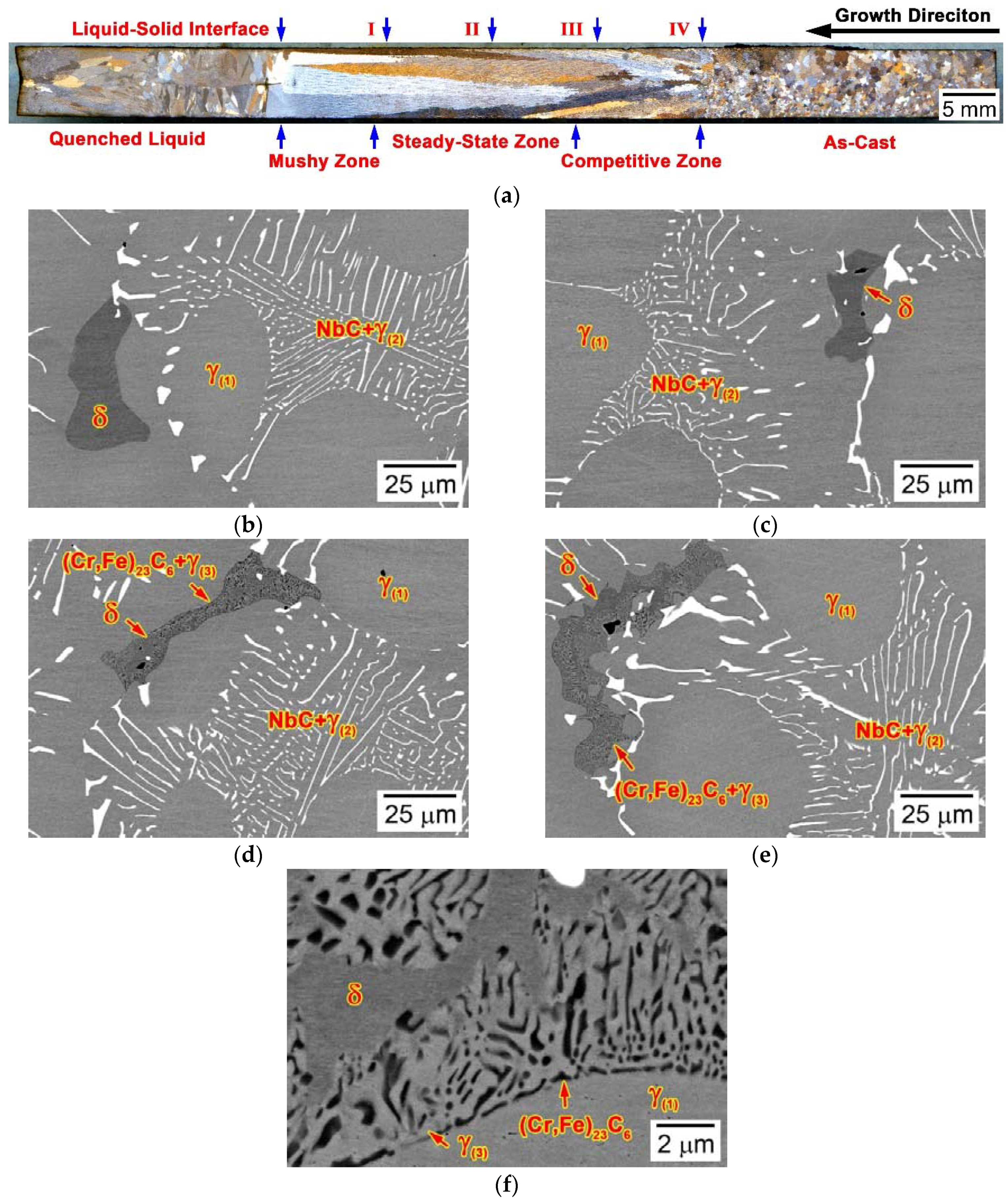
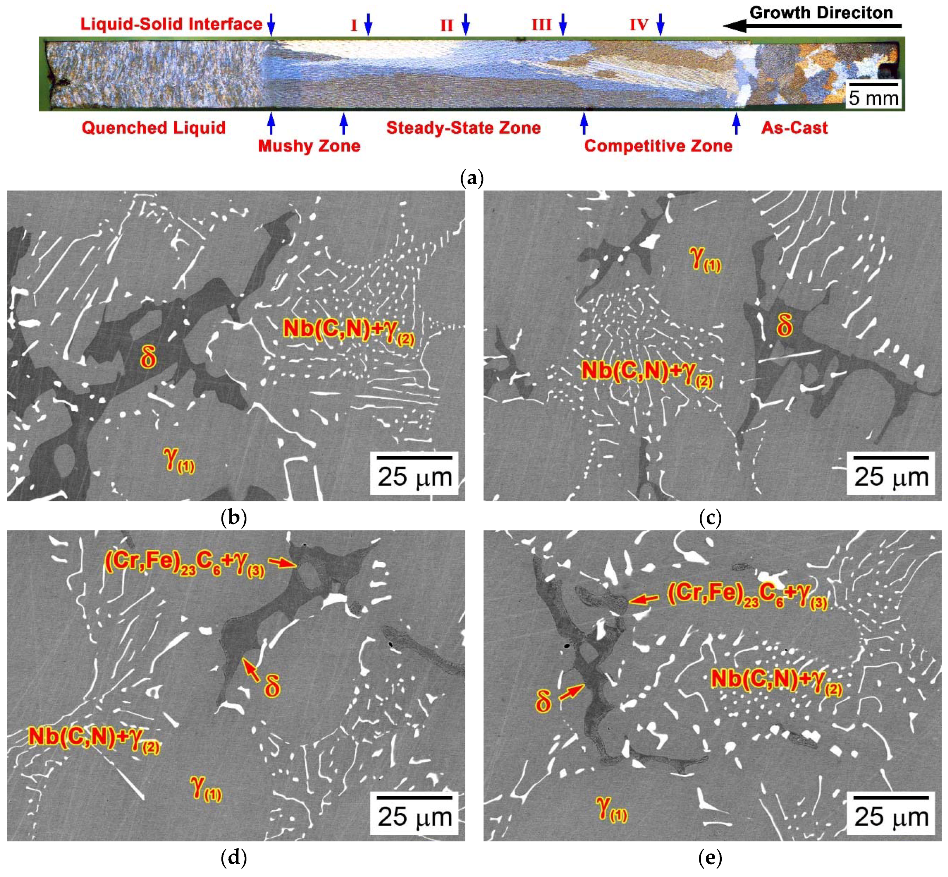
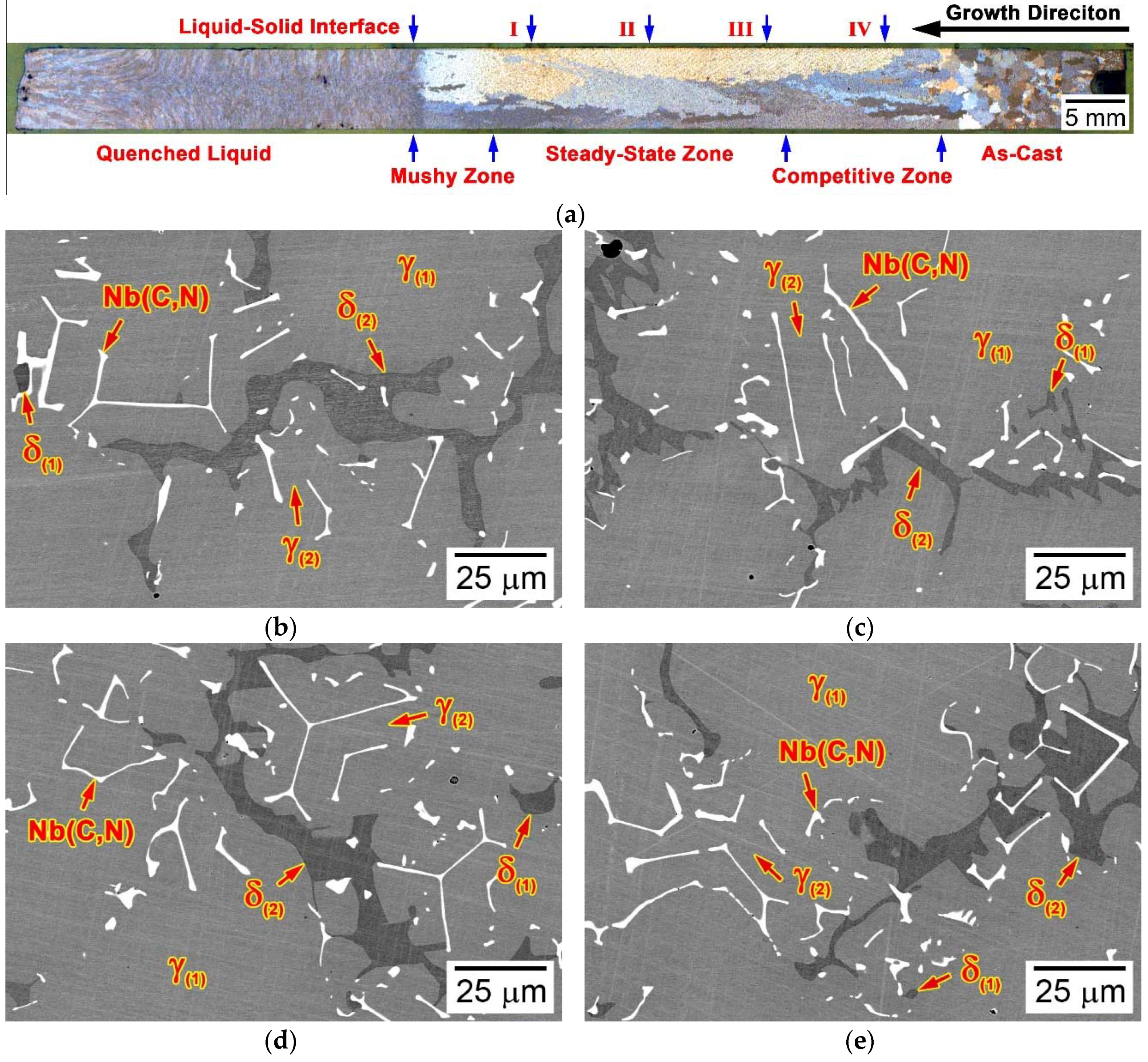
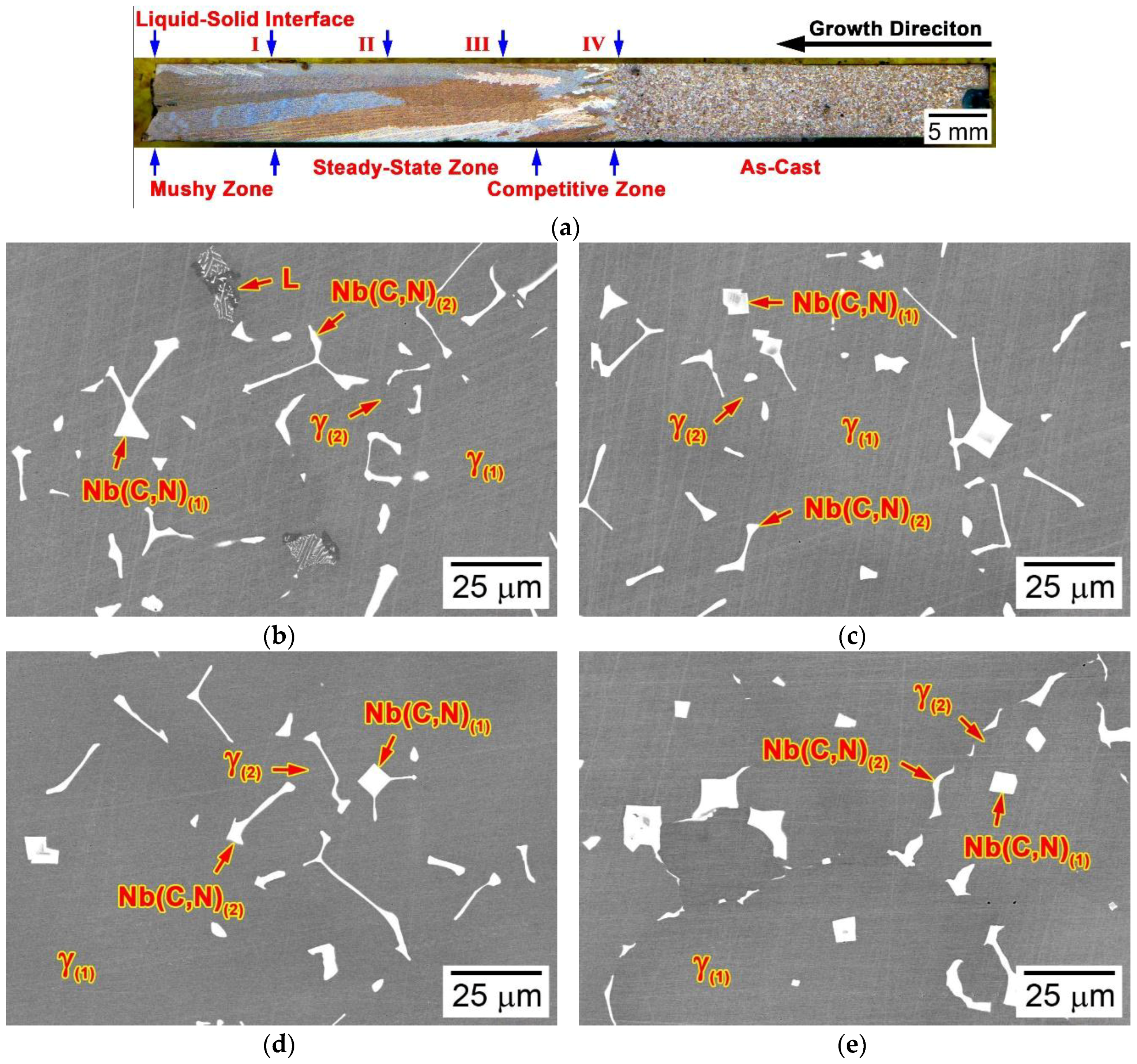
3.3. Microstructural Developments during Directional Solidification

3.3.1. Alloy 4C0N (Script Model)

Figure 5a is an optical image showing the liquid-metal quenched longitudinal macro-grain structure of alloy 4C0N, after the LMC-DS processing. According to the fraction of solid phase and the grain size, the macro-grain structure can be classified into five distinct zones comprising the quenched liquid zone, the mushy zone, the steady-state zone, the competitive zone, and the as-cast zone. The quenched liquid zone consisted of fine equiaxed grains, which were grown by quenching the molten liquid phase at the end of the LMC-DS processing. The mushy zone, the steady-state zone, and the competitive zone formed during the LMC-DS processing, showing the columnar grains growing throughout these three zones, with the average grain length of 19.9 ± 7.3 mm and the average grain width of 1.0 ± 0.2 mm. The as-cast zone was connected to the chill plate, such that its fine macro-grain structure was retained well as the LMS-DS processing finished. In order to clarify the precipitation behavior of (Cr,Fe)23C6 carbide, more attention was paid to the microstructural evolution in the steady-state zone and the competitive zone, as a function of the distance away from the liquid-solid interface.
Figure 5b–e are SEM-BSE images taken at typical locations in the steady-state zone and the competitive zone, every 10 mm away from the liquid-solid interface in Figure 5a. These locations were denoted as location I (10 mm), location II (20 mm), location III (30 mm), and location IV (40 mm) with decreasing the temperature. The microstructure at location I, was composed of solidified NbC carbide and δ-ferrite (Figure 5b). This NbC carbide exhibited the typical “Chinese-script” morphology and retained this feature in the as-cast microstructure (Figure 2a). At location II, the residual δ-ferrite had completely solidified and showed the vermicular morphology in the interdendritic regions (Figure 5c). Figure 5d shows the solid phase transformation at location III, where the (Cr,Fe)23C6 carbide precipitated through a typical eutectoid reaction:
δ → γ + (Cr,Fe)23C6
Figure 5f is an enlarged SEM-BSE image of typical (Cr,Fe)23C6 carbide and δ-ferrite, acquired from Figure 5d. It reveals that the (Cr,Fe)23C6 carbide occupied the majority of the δ-ferrite colony and showed thicker rods and sheets than that in the as-cast microstructure. The final solid phase transformation occurred at location IV (Figure 5e), whereas it showed similar microstructural characteristics to that at location III.

3.3.2. Alloy 3C2N (Script Model)

Figure 6a is an optical image showing the liquid-metal quenched longitudinal macro-grain structure of alloy 3C2N, after the LMC-DS processing. It revealed that this DS bar was composed of five distinct zones (the quenched liquid zone, the mushy zone, the steady-state zone, the competitive zone, and the as-cast zone), similar to that of alloy 4C0N. However, the equiaxed grains in the quenched liquid zone, grown during the final quenching processing were significantly smaller than that in alloy 4C0N. The average grain length and width of the columnar grains forming through the mushy zone to the steady-state zone and to the competitive zone, were determined to be 21.5 ± 8.2 and 1.7 ± 0.6 mm, respectively. The macro-grain structure in the as-cast zone remained well after the LMC-DS processing, showing coarser equiaxed grains than that in alloy 4C0N. It should be noted that the microstructural evolution in the steady-state zone and the competitive zone, was also characterized in detail to illustrate the precipitation behavior of (Cr,Fe)23C6 carbide.
Figure 6b–e are SEM-BSE images taken at typical locations in the steady-state zone and the competitive zone, every 10 mm away from the liquid-solid interface in Figure 6a. These locations were also denoted as location I (10 mm), location II (20 mm), location III (30 mm), and location IV (40 mm) with decreasing the temperature. The microstructural evolution in the steady-state zone and the competitive zone of alloy 3C2N was extremely similar to that of alloy 4C0N. Figure 6b shows that the microstructure of alloy 3C2N at location I, consisted of the “Chinese-script” Nb(C,N) carbonitride and the large, vermicular δ-ferrite. At location II, the size of the δ-ferrite decreased, whilst the size and morphology of the Nb(C,N) carbonitride remained stable (Figure 6c). As temperature continued to decrease, a typical eutectoid reaction (Equation (1)) occurred at location III (Figure 6d), where the (Cr,Fe)23C6 carbide precipitated in the colony of the residual δ-ferrite. Figure 6f is an enlarged SEM-BSE image of typical (Cr,Fe)23C6 carbide and δ-ferrite, acquired from Figure 6d. It illustrates that the (Cr,Fe)23C6 carbide was composed of rods and sheets similar to that in alloy 4C0N, but with smaller sizes. This solid phase transformation ended at location IV, where the morphology and distribution of the (Cr,Fe)23C6 carbide and δ-ferrite were well kept (Figure 6e).

3.3.3. Alloy 2C2N (Flake-Blocky Model)

Figure 7a is an optical image showing the liquid-metal quenched longitudinal macro-grain structure of alloy 2C2N, after the LMC-DS processing. It shows similar macro-grain structure with that of alloys 4C0N and 3C2N, which were classified into five distinctive zones comprising the quenched liquid zone, the mushy zone, the steady-state zone, the competitive zone, and the as-cast zone. The quenched liquid zone was composed of extremely fine equiaxed grains, whilst the as-cast zone consisted of the relatively coarser grains. The columnar grains grew from the competitive zone to the steady-state zone and then to the mushy zone, with the average grain length and width determined to be 11.6 ± 8.9 and 1.7 ± 0.9 mm, respectively. The microstructures of the steady-state zone and the competitive zone were further characterized to illustrate the solid-phase transformation, after the liquid-solid solidification finished.
Figure 7b–e are SEM-BSE images taken at typical locations in the steady-state zone and the competitive zone, every 10 mm away from the liquid-solid interface in Figure 7a. These locations were denoted as location I (10 mm), location II (20 mm), location III (30 mm), and location IV (40 mm) with decreasing the temperature. The microstructures at the four locations exhibited similar characteristics, consisting of the mixed flake-blocky Nb(C,N) carbonitride and the large, vermicular δ-ferrite. The quantity and size of the residual δ-ferrite did not change upon cooling to room temperature, and none of (Cr,Fe)23C6 carbide was observed in such cooling process.

3.3.4. Alloy 2C4N (Blocky Model)

Figure 8a is an optical image showing the liquid-metal quenched longitudinal macro-grain structure of alloy 2C4N, after the LMC-DS processing. Different from alloys 4C0N, 3C2N, and 2C2N, the DS bar of alloy 2C4N was composed of four distinctive zones comprising the mushy zone, the steady-state zone, the competitive zone, and the as-cast zone. The quenched liquid zone disappeared, leaving small liquid areas and some shrinkage voids near the liquid-solid interface. This DS bar ruptured along the liquid-solid interface during the final liquid metal cooling process, and this rupture phenomenon took place again during the repeated experiment. However, this rupture did not alter the macro-grain structure of the existing four zones. Figure 8a shows that columnar grains formed throughout the mushy zone, the steady-state zone, and the competitive zone, with the average grain length of 14.3 ± 8.7 mm and the average grain width of 1.4 ± 0.4 mm. The macro-grain structure of the as-cast zone was consistent to the as-cast ingot, consisting of fine equiaxed grains with much smaller size than that of the other alloys. Similarly, the microstructures of the steady-state zone and the competitive zone were further investigated to clarify the solid phase transformation behavior during the cooling process.
Figure 8b–e are SEM-BSE images taken at typical locations in the steady-state zone and the competitive zone, every 10 mm away from the liquid-solid interface in Figure 8a. These locations were denoted as location I (10 mm), location II (20 mm), location III (30 mm), and location IV (40 mm) with decreasing the temperature. Figure 8b shows that the microstructure at location I, was composed of solidified Nb(C,N) carbonitride and a small amount of residual liquid phase. These Nb(C,N) carbonitrides exhibited the mixed flake-blocky morphologies, whereas the proportion of the blocky ones was significantly higher than that in alloy 2C2N. At location II, none of residual δ-ferrite was observed, neither on the dendritic cores nor in the interdendritic regions (Figure 8c), and this microstructural characteristic was kept at location III and location IV (Figure 8d,e). It should be noted that none of (Cr,Fe)23C6 carbide was observed in the whole steady-state zone and the competitive zone during cooling to room temperature.

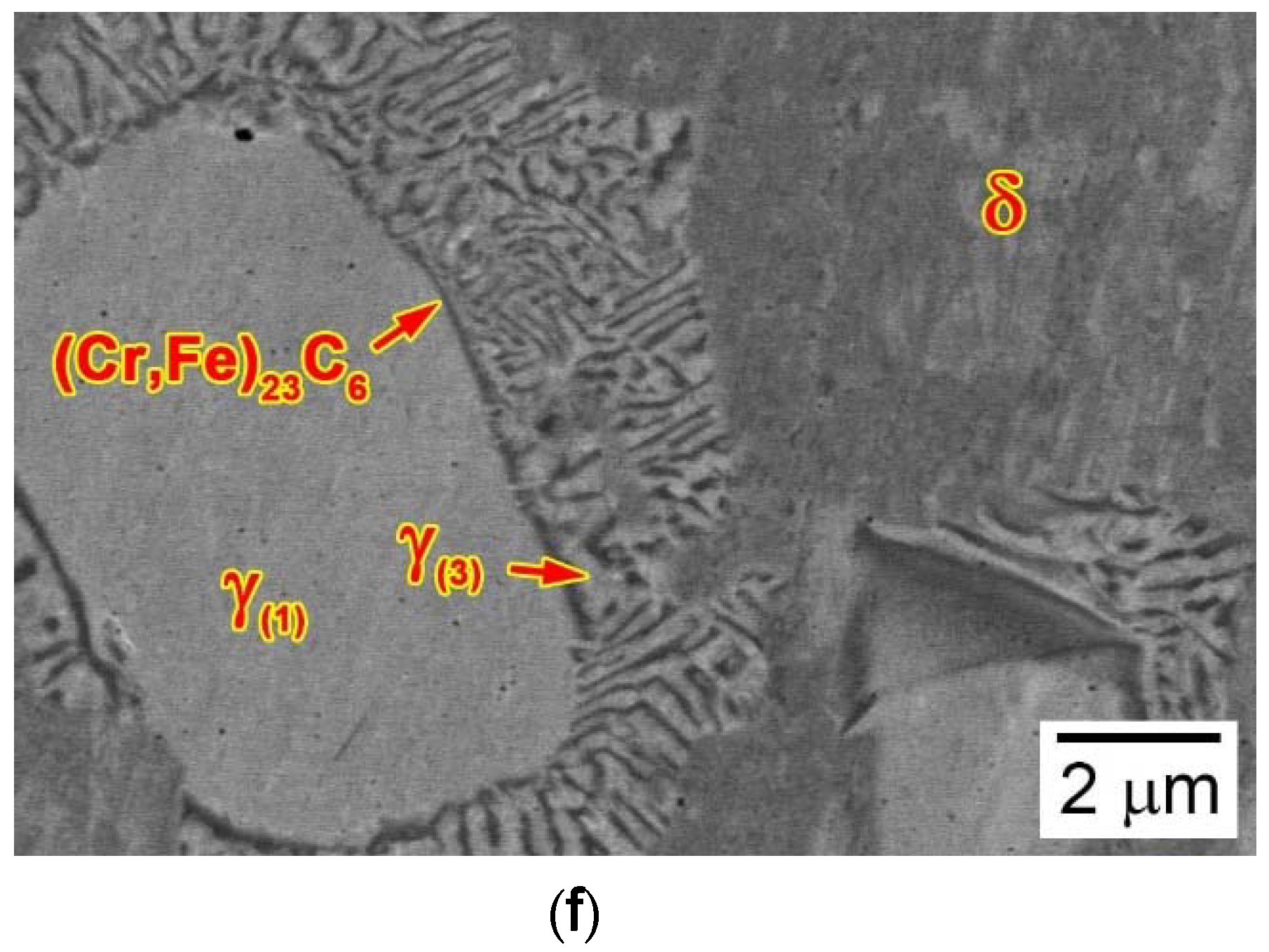
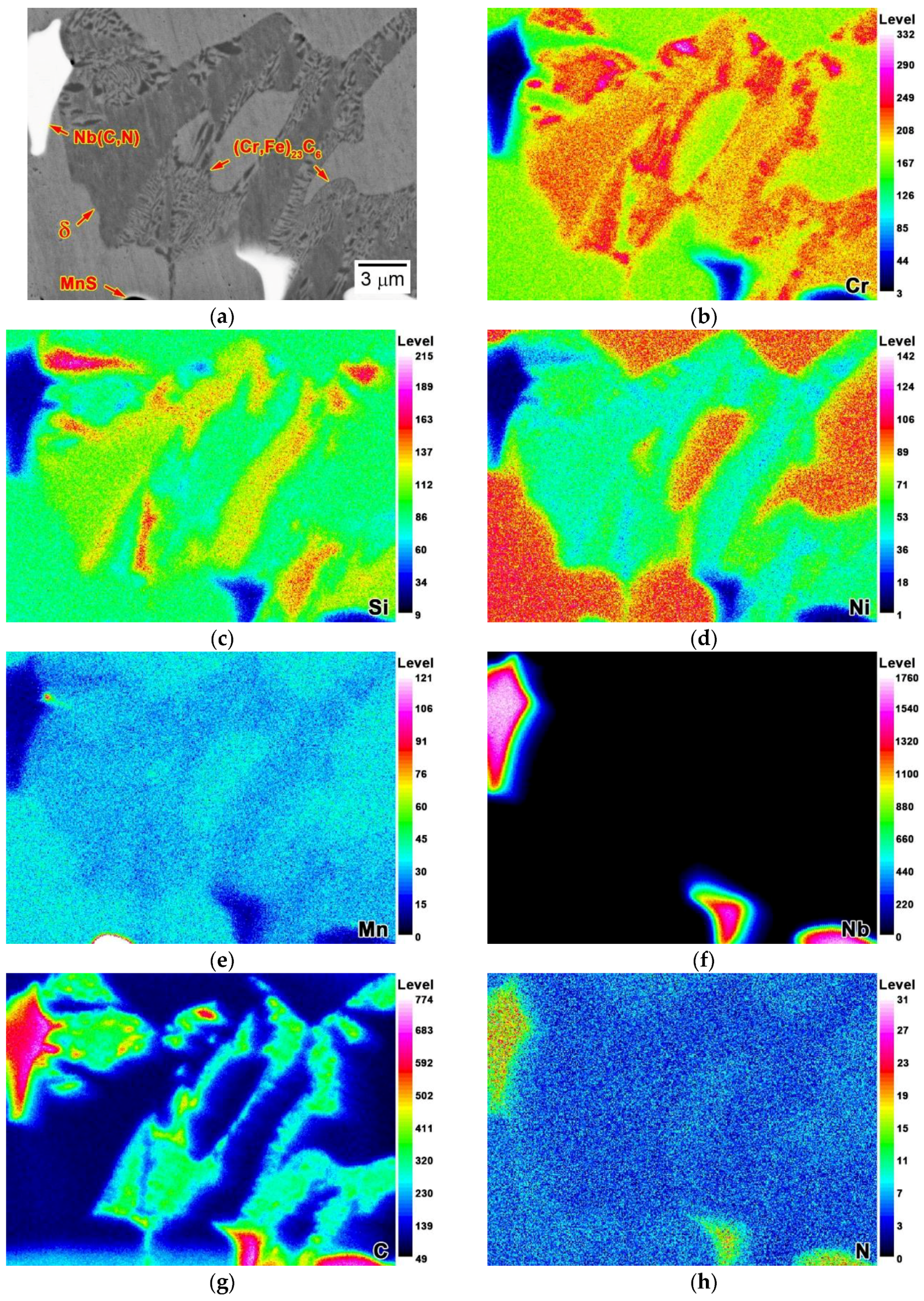
3.4. Composition of (Cr,Fe)23C6 Carbide and δ-Ferrite

Figure 9a is an EPMA-BSE image of (Cr,Fe)23C6 carbide and δ-ferrite at location III, in alloy 3C2N, and their compositional maps for Cr, Si, Ni, Mn, Nb, C and N are shown in Figure 9b–h. The large, vermicular δ-ferrite exhibited distinctive compositions, compared to the cellular (Cr,Fe)23C6 carbide, in spite of the similar contrasts. The two phases were enriched in Cr (Figure 9b) and depleted in austenite stabilizers, including Ni, Mn, and N (Figure 9d,e,h). The majority of Nb was consumed to form the Nb(C,N) carbonitride, thus showing significant depletion in both phases (Figure 9f). Si is a typical ferrite stabilizer, but its enrichment was observed only in the residual δ-ferrite, as shown in Figure 9c. C is a strong austenite stabilizer and carbide-forming element, and its enrichment occurred in the cellular (Cr,Fe)23C6 carbide near the δ-ferrite (Figure 9g). Such different distributions of Si and C implied a compositional segregation during the solid phase transformation (eutectoid reaction), upon cooling to room temperature.

4. Discussion

Microstructural characterization demonstrates that the microstructures of the four as-cast alloys were composed of the NbC/Nb(C,N) carbonitride with white contrast, the vermicular residual δ-ferrite with black contrast, and the cellular (Cr,Fe)23C6 carbide with black contrast (Figure 2). According to the morphology of NbC/Nb(C,N) carbonitride, these alloys were classified into three microstructural models: script (alloys 4C0N and 3C2N), flake-blocky (alloy 2C2N), and blocky (alloy 2C4N). The formation mechanisms of NbC/Nb(C,N) carbonitride and δ-ferrite have been investigated in our previous study, using the LMC-DS method [22]. The “Chinese-script” NbC/Nb(C,N) carbonitride formed at lower positions of the mushy zone through the eutectic reaction, while the blocky one formed in the molten liquid before γ-austenite solidification. This is because the increase of the N/C ratio significantly increased the precipitation temperature of NbC/Nb(C,N) carbonitride. Moreover, the increase of the N/C ratio decreased the stability of γ-austenite, leading to the abundant δ-ferrite residing in the as-cast microstructure of alloy 2C2N. However, none of (Cr,Fe)23C6 carbide was observed in the mushy zone of these DS bars.
In our previous studies, these three model alloys exhibited different mechanical properties at 1000 °C, and the formation of (Cr,Fe)23C6 carbide and δ-ferrite was presumed to be the major deleterious factors, which accelerated the propagation of creep cracks (Figure 10) [3,8,9,10,11]. Therefore, it is important to clarify the formation mechanism of (Cr,Fe)23C6 carbide in these alloys. Thermodynamic calculations under the Scheil-Gulliver and equilibrium conditions, confirmed that the (Cr,Fe)23C6 carbide did not form within this liquid-solid transformation stage (Figure 3), but instead it formed during the eutectoid reaction after the solidification ended (Figure 4). This was verified by characterizing the microstructure of the steady-state zone and the competitive zone of these DS bars, where the precipitation of (Cr,Fe)23C6 carbide was observed (Figure 5f and Figure 6f).
The precipitation of (Cr,Fe)23C6 carbide occurred only in the script model alloys, with relatively low N/C ratios. Microstructural analyses at location I, in alloys 4C0N and 3C2N, indicated that the “Chinese-script” NbC/Nb(C,N) carbonitride and the large, vermicular δ-ferrite formed in the mushy zones, whilst the (Cr,Fe)23C6 carbide still did not precipitate when the solidification ended (Figure 5b and Figure 6b). This precipitation did not occur even as the temperature cooled to location II, suggesting that the temperature at this place was still higher than the precipitation temperature of (Cr,Fe)23C6 carbide (Figure 5c and Figure 6c). It is interesting that the size of the residual δ-ferrite decreased, indicating that a small part of δ-ferrite had transformed into the austenitic matrix. The (Cr,Fe)23C6 carbide had not precipitated through the eutectoid reaction, until the temperature cooled to location III, forming thin and lamellar morphologies in the colony of δ-ferrite, and moving the growth front towards the δ-ferrite (Figure 5f and Figure 6f). Such eutectoid reaction could be attributed to the enrichment of Cr in the residual δ-ferrite, thus significantly decreasing the diffusion time of Cr to form the (Cr,Fe)23C6 carbide (Figure 9). At location IV, this LMC-DS processing finished, leaving the residual δ-ferrite and the (Cr,Fe)23C6 carbide with the whole vermicular morphology (Figure 5e and Figure 6e), and this was consistent with the as-cast microstructure (Figure 2a,b).
The (Cr,Fe)23C6 carbide in alloys 2C2N and 2C4N, formed in the as-cast microstructure with cellular and vermicular morphologies, indicating that it precipitated in similar ways to that in alloys 4C0N and 3C2N, but with relatively small amounts (Table 2). Comparing the microstructures of the four alloys at location III, it was noted that the variation of the N/C ratio could affect the thermal stability of (Cr,Fe)23C6 carbide, thereby significantly altering its precipitation behavior. Thermodynamic calculations under the equilibrium condition, suggested that increasing the N/C ratio could have significantly decreased the precipitation temperature of (Cr,Fe)23C6 carbide, except for alloy 2C4N with a higher total content of C and N (Figure 4). As a result, the majority of the residual δ-ferrite in alloy 4C0N transformed into the (Cr,Fe)23C6 carbide at location III, with the highest precipitation temperature, leaving a few δ-ferrites in the vermicular colony (Figure 5d). In contrast, only a small part of δ-ferrite had transformed into the (Cr,Fe)23C6 carbide through the eutectoid reaction at location III in alloy 3C2N, with relatively lower precipitation temperature (Figure 6d). Due to the lowest precipitation temperature, the (Cr,Fe)23C6 carbide did not precipitate at location III in alloy 2C2N (Figure 7d). The residual δ-ferrite in alloy 2C2N showed extremely high thermal stability to retard this eutectoid reaction until it cooled to room temperature at location IV (Figure 7e). Although the precipitation temperature of (Cr,Fe)23C6 carbide in alloy 2C4N was almost equal to that of alloy 3C2N, its precipitation was completely prevented, since the relatively higher C and N contents stabilized the austenitic matrix and prohibited the solidification of δ-ferrite, thereby eliminating the eutectoid reaction during the whole LMC-DS process. Therefore, the precipitation of (Cr,Fe)23C6 carbide could be prevented, though increasing the N/C ratio of this type of alloys.
The quantity of the deleterious (Cr,Fe)23C6 carbide in alloys 2C2N and 2C4N had been limited at low levels, but they still exhibited worse creep resistance than alloys 4C0N and 3C2N at 1000 °C (Figure 10a). This is because the NbC/Nb(C,N) carbonitride with the “Chinese-script” morphology, significantly strengthened the grain boundary regions of alloys 4C0N and 3C2N [3]. Therefore, although it was suggested to limit the quantity of (Cr,Fe)23C6 carbide and δ-ferrite through adjusting the N/C ratio, the effect of the N/C ratio on the formation of NbC/Nb(C,N) carbonitride should be considered as well, if optimizing the alloy composition.

5. Conclusions

The precipitation behavior of (Cr,Fe)23C6 carbide in a series of novel Nb-bearing cast austenitic heat-resistant steels, with variations in N/C ratio, were investigated in the current study. The formation mechanism of (Cr,Fe)23C6 carbide was clarified, which can provide guidance to optimizing the alloy composition. Conclusions are drawn.
  • Different from the NbC/Nb(C,N) carbonitride and δ-ferrite that formed in the mushy zones, the (Cr,Fe)23C6 carbide formed in the steady-state zone and the competitive zone upon cooling to room temperature, after the solidification finished.
  • Both the (Cr,Fe)23C6 carbide and δ-ferrite were enriched in Cr and depleted in Nb, Ni, Mn, and N, whereas the two phases showed different concentrations of C and Si, depending on which they were recognized as carbide and δ-ferrite.
  • The (Cr,Fe)23C6 carbide grew in the colony of the δ-ferrite through the eutectoid reaction, forming fine rods and sheets that comprised the cellular structure, and moving the growth front towards the δ-ferrite.
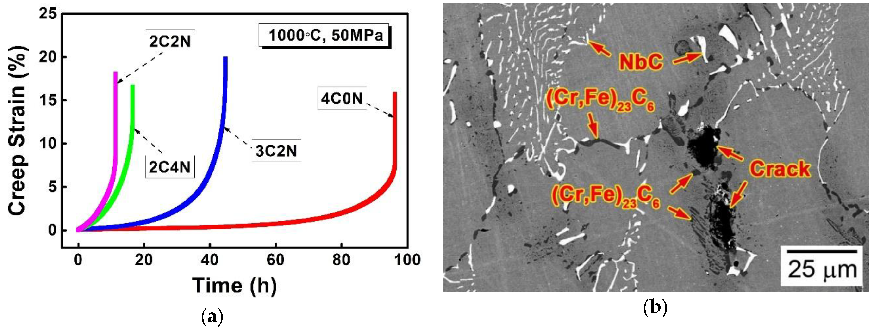
  • The precipitation temperature of (Cr,Fe)23C6 carbide decreased significantly with increasing the N/C ratio, giving rise to the prevention of this carbide precipitation during the liquid metal cooling directional solidification process.

Author Contributions

Y.Z. conceived and designed this research. Y.Z. performed the experiments and simulations. Y.Z. analyzed the experimental results and wrote this manuscript. J.Y. contributed the consultation and paper preparation. J.Y. contributed correction of English and proofreading.

Funding

This research was supported by the Project funded by China Postdoctoral Science Foundation (2017M621430) and the University Research Program (URP) between Ford Motor Company, USA and University of Science and Technology Beijing.

Acknowledgments

The authors are grateful to Q. Feng and M. Li for suggestions on designing this research; L.W. Zhang and X.F. Zhang are also acknowledged, specially for the full support on directional solidification experiments and materials characterizations, respectively.

Conflicts of Interest

The authors declare no conflict of interest.

References

  1. Kunanoppadon, J. Thermal efficiency of a combined turbocharger set with gasoline engine. Am. J. Eng. Appl. Sci. 2010, 3, 342–349. [Google Scholar] [CrossRef]
  2. Matsumoto, K.; Tojo, M.; Jinnai, Y.; Hayashi, N.; Ibaraki, S. Development of compact and high-performance turbocharger for 1050 °C exhaust gas. Mitsubishi Heavy Ind. Tech. Rev. 2008, 45, 1–5. [Google Scholar]
  3. Zhang, Y.H.; Li, M.; Godlewski, L.A.; Zindel, J.W.; Feng, Q. Creep behavior at 1273 K (1000 °C) in Nb-bearing austenitic heat-resistant cast steels developed for exhaust component applications. Metall. Mater. Trans. A 2016, 47, 3289–3294. [Google Scholar] [CrossRef]
  4. Zhao, H.L.; Engler-Pinto, C.C.; Tong, J.Y.; Godlewski, L.A.; Zindel, J.W.; Li, L.F.; Li, M.; Feng, Q. Mechanical response and dislocation substructure of a cast austenitic steel under low cycle fatigue at elevated temperatures. Mater. Sci. Eng. A 2017, 703, 422–429. [Google Scholar] [CrossRef]
  5. Shingledecker, J.P.; Maziasz, P.J.; Evans, N.D.; Pollard, M.J. Creep behavior of a new cast austenitic alloy. Int. J. Press. Vessels Pip. 2007, 84, 21–28. [Google Scholar] [CrossRef] [Green Version]
  6. Lo, K.H.; Shek, C.H.; Lai, J.K.L. Recent developments in stainless steels. Mater. Sci. Eng. R Rep. 2009, 65, 39–104. [Google Scholar] [CrossRef]
  7. Buchanan, K.G.; Kral, M.V.; Bishop, C. Crystallography and morphology of MC carbides in niobium-titanium modified as-cast HP alloys. Metall. Mater. Trans. A 2014, 45, 3373–3385. [Google Scholar] [CrossRef]
  8. Zhang, Y.H.; Li, M.; Godlewski, L.A.; Zindel, J.W.; Feng, Q. Effects of N on creep properties of austenitic heat-resistant cast steels developed for exhaust component applications at 1000 °C. Acta Metall. Sin. 2016, 52, 661–671. [Google Scholar]
  9. Zhang, Y.H.; Feng, Q. Effects of W on creep behaviors of novel Nb-bearing austenitic heat-resistant cast steels at 1000 °C. Acta Metall. Sin. 2017, 53, 1025–1037. [Google Scholar] [CrossRef]
  10. Zhang, Y.H.; Li, M.; Godlewski, L.A.; Zindel, J.W.; Feng, Q. Effective design of new austenitic cast steels for ultra-high temperature automotive exhaust components through combined CALPHAD and experimental approaches. Mater. Sci. Eng. A 2017, 683, 195–206. [Google Scholar] [CrossRef]
  11. Zhang, Y.H.; Li, M.; Godlewski, L.A.; Zindel, J.W.; Feng, Q. Effects of W on creep behaviors of novel Nb-bearing high nitrogen austenitic heat-resistant cast steels at 1000 °C. Mater. Charact. 2018, 139, 19–29. [Google Scholar] [CrossRef]
  12. Sourmail, T. Precipitation in creep resistant austenitic stainless steels. Mater. Sci. Technol. 2001, 17, 1–14. [Google Scholar] [CrossRef]
  13. McGuire, M.F. Stainless Steels for Design Engineers; ASM International: Materials Park, OH, USA, 2008; pp. 69–78. [Google Scholar]
  14. Erneman, J.; Schwind, M.; Liu, P.; Nilsson, J.O.; Andrén, H.O.; Ågren, J. Precipitation reactions caused by nitrogen uptake during service at high temperatures of a niobium stabilised austenitic stainless steel. Acta Mater. 2004, 52, 4337–4350. [Google Scholar] [CrossRef]
  15. Wasnik, D.N.; Dey, G.K.; Kain, V.; Samajdar, I. Precipitation stages in a 316L austenitic stainless steel. Scr. Mater. 2003, 49, 135–141. [Google Scholar] [CrossRef]
  16. Padilha, A.F.; Rios, P.R. Decomposition of austenite in austenitic stainless steels. ISIJ Int. 2002, 42, 325–327. [Google Scholar] [CrossRef]
  17. Hong, H.U.; Nam, S.W. The occurrence of grain boundary serration and its effect on the M23C6 carbide characteristics in an AISI 316 stainless steel. Mater. Sci. Eng. A 2002, 332, 255–261. [Google Scholar] [CrossRef]
  18. Kim, K.J.; Hong, H.U.; Min, K.S.; Nam, S.W. Correlation between the carbide morphology and cavity nucleation in an austenitic stainless steels under creep-fatigue. Mater. Sci. Eng. A 2004, 387–389, 531–535. [Google Scholar] [CrossRef]
  19. Kaneko, K.; Fukunaga, T.; Yamada, K.; Nakada, N.; Kikuchi, M.; Saghi, Z.; Barnard, J.S.; Midgley, P.A. Formation of M23C6-type precipitates and chromium-depleted zones in austenite stainless steel. Scr. Mater. 2011, 65, 509–512. [Google Scholar] [CrossRef]
  20. Ding, X.F.; Liu, D.F.; Zheng, Y.R.; Feng, Q. Effect of B micro-alloying on micro-porosities in as-cast HK40 alloys. Acta Metall. Sin. 2015, 51, 1121–1128. [Google Scholar]
  21. Ding, X.F.; Liu, D.F.; Guo, P.L.; Zheng, Y.R.; Feng, Q. Solidification microstructure formation in HK40 and HH40 alloys. Int. J. Min. Met. Mater. 2016, 23, 442–448. [Google Scholar] [CrossRef]
  22. Zhang, Y.H.; Li, M.; Godlewski, L.A.; Zindel, J.W.; Feng, Q. Effects of N/C ratio on solidification behaviors of novel Nb-bearing austenitic heat-resistant cast steels for exhaust components of gasoline engines. Metall. Mater. Trans. A 2017, 48, 1151–1162. [Google Scholar] [CrossRef]
  23. Miller, J.D.; Pollock, T.M. Stability of dendrite growth during directional solidification in the presence of a non-axial thermal field. Acta Mater. 2014, 78, 23–36. [Google Scholar] [CrossRef]
  24. Ding, X.F.; Lin, J.P.; Zhang, L.Q.; Wang, H.L.; Hao, G.J.; Chen, G.L. Microstructure development during directional solidification of Ti–45Al–8Nb alloy. J. Alloy. Compd. 2010, 506, 115–119. [Google Scholar] [CrossRef]
Figure 1. (a) Appearance and (b) schematic illustration of the liquid metal cooling (LMC) type directional solidification apparatus; (c) Optical image of a typical experimental bar after the LMC-DS processing.
Metals 08 00678 g001
Figure 2. SEM-BSE images showing the typical microstructures of as-cast alloys (a) 4C0N, (b) 3C2N, (c) 2C2N, and (d) 2C4N; (e) and (f) are enlarged SEM-BSE images of typical (Cr,Fe)23C6 carbide acquired from Figure 2a,b, respectively.
Metals 08 00678 g002
Figure 3. Phase diagrams of alloys (a) 4C0N and (b) 2C4N calculated by JMatPro software under the Scheil-Gulliver condition and plotted as a function of temperature.
Metals 08 00678 g003
Figure 4. Mass fractions of (Cr,Fe)23C6 carbide calculated by JMatPro software under the equilibrium condition and plotted as a function of temperature.
Metals 08 00678 g004
Figure 5. (a) Optical image of alloy 4C0N showing the liquid-metal quenched longitudinal macro-grain structure of the DS bar after the LMC-DS processing; SEM-BSE images were taken at distances of (b) 10, (c) 20, (d) 30, and (e) 40 mm away from the liquid-solid interface in Figure 5a, showing the microstructural evolution in the steady-state zone and the competitive zone; (f) is an enlarged SEM-BSE image of typical (Cr,Fe)23C6 carbide and δ-ferrite acquired from Figure 5d.
Metals 08 00678 g005
Figure 6. (a) Optical image of alloy 3C2N showing the liquid-metal quenched longitudinal macro-grain structure of the DS bar after the LMC-DS processing; SEM-BSE images were taken at distances of (b) 10, (c) 20, (d) 30, and (e) 40 mm away from the liquid-solid interface in Figure 6a, showing the microstructural evolution in the steady-state zone and the competitive zone; (f) is an enlarged SEM-BSE image of typical (Cr,Fe)23C6 carbide and δ-ferrite acquired from Figure 6d.
Metals 08 00678 g006aMetals 08 00678 g006b
Figure 7. (a) Optical image of alloy 2C2N showing the liquid-metal quenched longitudinal macro-grain structure of the DS bar after the LMC-DS processing; SEM-BSE images were taken at distances of (b) 10, (c) 20, (d) 30, and (e) 40 mm away from the liquid-solid interface in Figure 7a, showing the microstructural evolution in the steady-state zone and the competitive zone.
Metals 08 00678 g007
Figure 8. (a) Optical image of alloy 2C4N showing the liquid-metal quenched longitudinal macro-grain structure of the DS bar after the LMC-DS processing; SEM-BSE images were taken at distances of (b) 10, (c) 20, (d) 30, and (e) 40 mm away from the liquid-solid interface in Figure 8a, showing the microstructural evolution in the steady-state zone and the competitive zone.
Metals 08 00678 g008
Figure 9. (a) EPMA-BSE image and compositional maps for (b) Cr, (c) Si, (d) Ni, (e) Mn, (f) Nb, (g) C, and (h) N of (Cr,Fe)23C6 carbide and δ-ferrite taken at location III in Figure 6a.
Metals 08 00678 g009
Figure 10. (a) Creep strain-time curves of the as-cast alloys tested at 1000 °C and 50 MPa; (b) SEM-BSE image showing the typical creep cracks in alloy 4C0N after creep ruptured.
Metals 08 00678 g010
Table 1. Measured chemical compositions of the as-cast alloys (wt %).
AlloyFeCrNiSiMnNbSPCNN+CN/C
4C0NBal.18.429.160.490.862.000.0070.0130.400.010.410
3C2NBal.19.6810.120.800.932.090.0080.0130.290.150.440.52
2C2NBal.20.919.600.860.952.160.0080.0140.210.220.431.05
2C4NBal.21.329.880.920.952.180.0070.0140.230.360.591.57
Table 2. Area fractions of precipitates in these alloys, measured by digital image-analysis technique.
AlloyNbC/Nb(C,N)(Cr,Fe)23C6δ
4C0N2.91.10.0
3C2N2.81.40.1
2C2N2.80.53.1
2C4N2.90.4Trace

