Strength Analysis of a Novel High-Pressure Die with Double-Layered Split Structure

1
Roll Forging Institute, Jilin University, Changchun 130025, China
2
College of Materials Science and Engineering, Jilin University, Changchun 130025, China
3
Changchun Ruiguang Science & Technology Co., Ltd, Changchun 130025, China
*
Authors to whom correspondence should be addressed.
Metals 2018, 8(8), 606; https://doi.org/10.3390/met8080606
Submission received: 8 July 2018
/
Revised: 31 July 2018
/
Accepted: 1 August 2018
/
Published: 3 August 2018
Abstract
:A novel double-layered split die (DLSD) was designed to have higher pressure-bearing capacity and larger sample cavity volume. In DLSD, the cylinder and first layer supporting ring are split into several blocks. It has a prismatic cylinder and a quasi-prismatic sample cavity. The stress distribution of DLSD was investigated and compared with that of the conventional belt-type die (BTD) and a single-layered split die (SLSD) by the finite element method. The results show that the SLSD can only decrease the stress of the cylinder as there remains significant stress on the first layer supporting ring. However, the novel DLSD can, remarkably, decrease the stress placed on the cylinder and first layer supporting ring simultaneously due to the improvement of the stress states. Additionally, the maximum stress and pressure-bearing capacity of DLSD with different numbers of split blocks were further investigated. It is concluded that the maximum stress of the cylinder increases gradually with an increase in the number of split blocks. Meanwhile, the pressure-bearing capacity decreases accordingly. The experiments show that the pressure-bearing capacities of DLSD with 4 and 8 split blocks are all remarkably higher than that of the BTD. DLSD with 4 split blocks has relatively higher pressure-bearing capacity. This work presents a promising high-pressure die with a double-layered split structure for the synthesis of superhard materials.
1. Introduction
Superhard materials, such as the well-known diamond and cubic boron nitride (cBN), have been increasingly used for cutting, grinding, sawing, drilling and polishing difficult-to-process materials due to their extremely unique physicochemical characteristics [1,2,3]. The belt apparatus has been the most extensively used device for synthesizing diamond and cBN since being pioneered by Hall [4,5,6]. The belt apparatus mainly consists of a belt-type die (BTD) and two opposed anvils. The BTD is assembled by a tungsten carbide cylinder and multilayered high-strength alloy steel supporting rings as shown in Figure 1a. The cylinder possesses a central sample cavity, which contains the mixture for synthesizing superhard materials that is surrounded by a pressure transmission medium (generally pyrophyllite). They are compressed by the two opposed anvils driven by hydraulic actuators. This leads to a redistribution of pressure in the sample cavity so that the high hydrostatic pressure for synthesizing superhard material is achieved [7,8].
As the core part of belt apparatus, effort has been made to improve the pressure-bearing capacity and enlarge the sample cavity volume of BTD. This not only helps to improve the quality and efficiency of high-pressure synthesis of superhard materials but also aims to prolong the service life of high-pressure die [9,10]. However, the tungsten carbide cylinder usually generates great tensile stress and shear stress when the belt apparatus is running. This greatly limits the pressure-bearing capacity and service life of BTD, which inevitably increases the manufacturing costs for the synthesis of superhard materials. In addition, a large sample cavity volume requires a tungsten carbide cylinder with a large size. The tungsten carbide component is manufactured by powder metallurgy and it is not easy to produce large-sized tungsten carbide components with sufficiently good quality under the current technical conditions [11]. Therefore, the enlargement of sample cavity is limited by the availability of large tungsten carbide components for the cylinder that can sustain the high pressure.
In recent years, the emerging split-type high-pressure die based on the BTD has received increasing attention. This mainly has the following two outstanding advantages. On the one hand, by splitting the tungsten carbide cylinder into several blocks, it is possible to eliminate the circumferential tensile stress and improve the pressure-bearing capacity. On the other hand, the size of single tungsten carbide cylinder can be dramatically reduced after it is split. Thus, this can avoid the formidable problem of sintering large-sized tungsten carbide components. This makes it possible to realize a larger sample cavity of the high-pressure die. Liu et al. [12] developed a multi-layer split high-pressure die which is capable of bearing higher pressures than the BTD. However, the cylinder is not pre-stressed to avoid placing a large amount of stress on the supporting rings. As a result, the cylinder generates a large radial displacement, thus limiting its practical applications. Wang et al. [13] studied a double-beveled multi-layer split high-pressure die. It has higher pressure-bearing capacity due to the lateral support of double bevels. However, the outer supporting ring is under a large amount of stress and is prone to fracture. Yang et al. [14] designed a tangent split high-pressure die, which can sustain greater pressure due to the reasonable stress distribution of cylinder. Unfortunately, this split way leads to extremely large stress being placed on the first layer supporting ring.
In this study, to obtain higher pressure-bearing capacity and larger sample cavity, a novel high-pressure die with double-layered split structure (we called this double-layered split die; DLSD) was designed based on the principles of massive support and lateral support. In DLSD, the cylinder and first layer supporting ring are equally split into several blocks. The cylinder is not round but a regular prism. Furthermore, the cylinder blocks with the plane of the inner wall define a quasi-prismatic central sample cavity. Each supporting ring block interacts with two cylinder blocks. This special geometry of split blocks makes it possible to take advantage of the massive support principle both for the cylinder and first layer supporting ring. Furthermore, the split blocks squeeze each other to provide lateral support. It is well known that massive support and lateral support are very helpful in decreasing the stress of components. Therefore, the pressure-bearing capacity of high-pressure die can be improved. Meanwhile, the inner wall of cylinder block with a plane structure helps to effectively eliminate circumferential tensile stress and make the stress state much closer to hydrostatic stress. Similarity, the stress state of first layer supporting ring could be also improved. After this, lower stress levels of cylinder and first layer supporting ring are expected to be achieved, which will result in higher pressure-bearing capacity and longer service life of high-pressure die. In addition, the splitting of tungsten carbide cylinder into several blocks with an obviously smaller size can also help to reduce the manufacturing difficulty and improve the sintering quality of tungsten carbide component for the cylinder. Therefore, it is beneficial to obtain higher pressure-bearing capacity and achieve larger sample cavity volume.
In order to embody the superiority of novel DLSD, a single-layered split die (abbreviated to SLSD) is also studied as a comparison in addition to the conventional BTD in this work. In SLSD, only the cylinder is split into several blocks in the radial direction and the supporting rings are the same as BTD. Additionally, SLSD has a round cylinder that is similar to the BTD and an identical quasi-prismatic sample cavity with the DLSD. The SLSD and novel DLSD are schematically shown in Figure 1b,c.
Finite element analysis (FEA) as a method for modelling the behavior of mechanical components and strength of structure has been proven to be powerful and widely used for the design and optimization of high-pressure vessels and devices [15,16,17,18]. In the present study, we aim to investigate the stress distribution of the novel DLSD and compare it with that of the conventional BTD and SLSD by the FEA method. Firstly, the finite element models were discussed and constructed, including the geometry, material and numerical model. Following this, the stress distributions of BTD, SLSD (4 split blocks) and DLSD (4 split blocks) were studied. Afterwards, the stress states of BTD and DLSD (4 split blocks) were investigated. Subsequently, the effects of split block number on the maximum stresses of cylinder and first layer supporting ring as well as on the pressure-bearing capacity of DLSD were discussed. Finally, destructive experiments of high-pressure dies were implemented to validate the numerical results by testing the pressure-bearing capacity.
2. Finite Element Modelling
2.1. Geometric Model
For better conformation to the actual situation, the geometric size of BTD is obtained from Reference [19], which is shown in Figure 2a. The external radius of cylinder is 30 mm and the radius of the cylindrical sample cavity is 5 mm. SLSD has the same geometric size with the BTD except for the sample cavity. The prismatic sample cavity of SLSD is circumscribed in the circular cavity of BTD. Essentially, the prismatic sample cavity size is 10 mm × 10 mm. DLSD has a geometric size of the sample cavity that is identical to the SLSD. However, unlike BTD or SLSD, as illustrated in Figure 2b, the prismatic cylinder is inscribed in the circular first layer supporting ring of BTD (or SLSD). In other words, the circumscribed circle radius of prismatic cylinder for DLSD is 30 mm. Three types of high-pressure dies have the identical outer radii for supporting rings (I–IV) of 41.5, 57.4, 79.4 and 110 mm, respectively. They also have the identical sample cavity height of 12 mm, total die height of 30 mm and cylinder taper angle of 45°. In addition, proper interference fits between the adjacent layers are indispensable in order to pre-stress the cylinder. The interference fits from the internal to external layer are 0.123, 0.142, 0.195 and 0.268 mm, respectively.
2.2. Material Model
The material used in the cylinder is tungsten carbide (8 wt % cobalt, YG8) and the supporting rings are made of high-strength alloy steel (45CrNiMoVA). To obtain generic results, we considered the simplest model for isotropic, linearly elastic material. Furthermore, the elastic constants are as follows: Young’s modulus E = 578 GPa, Poisson ratio ν = 0.21 for tungsten carbide; and E = 210 GPa, ν = 0.29 for alloy steel [20,21]. Herein, the von Mises yield criterion is employed to assess whether the failure occurs for tungsten carbide cylinder and alloy steel supporting rings. According to this criterion, the material failure will occur when the magnitude of von Mises stress (σVM) exceeds a critical stress (σf) where σf is the failure strength. We used the failure stress σf = 6200 MPa for the tungsten carbide cylinder [22,23]; and used the failure stress σf = 1330 MPa for the alloy steel supporting ring [10,24]. There is no doubt that a decrease in the von Mises stress of high-pressure die helps to attain higher structural strength and pressure-bearing capacity, which ultimately results in a longer service life. The corresponding parameters of tungsten carbide and high-strength alloy steel are presented in Table 1.
2.3. Numerical Model
FEA calculations were performed for high-pressure dies using the commercial software ABAQUS/Standard. A pressure load acting on the inner wall of sample cavity was assumed to be uniformly distributed with the value of 6500 MPa. The Newton–Raphson iterative algorithm was employed for calculation. According to the model feature of high-pressure die, a cylindrical coordinate (R, T, Z) was established. Considering the symmetry in axial direction (Z), 1/2 model was established with the axial displacement of symmetric surface constrained (UZ = 0). The displacement in T-direction of outer cylindrical surface of supporting ring (IV) was set to zero (UT = 0) to prevent any circumferential rotation. In addition, the friction formulation of penalty was employed to define the tangential behavior for the interaction between components. The friction coefficient was 0.25 at the interface between tungsten carbides; 0.2 between tungsten carbide and alloy steel; and 0.15 between the alloy steels [25]. Besides, the cylinders and supporting rings were all meshed with C3D8R and the sizes of mesh from the inner to outer layer were 0.5, 0.75, 1.0, 1.25 and 1.5 mm, respectively. The final numerical model of high-pressure die is shown in Figure 3. Here, only the novel DLSD model is presented due to the similarity of BTD, SLSD and DLSD.
3. Results and Discussion
3.1. Stress Analysis of the Cylinder
Figure 4 presents the von Mises stress distributions on the cylinders of BTD, SLSD and DLSD. The von Mises stress of BTD cylinder, as shown in Figure 4a, has a magnitude on the inner wall of sample cavity and decreases gradually in the radial direction. Furthermore, the maximum von Mises stress (7411 MPa) has exceeded the failure strength of tungsten carbide (6200 MPa). This indicates that the BTD cylinder has already fractured under the pressure load of 6500 MPa. SLSD and DLSD have roughly similar stress distributions as shown in Figure 4b,c. Being apparently different from the BTD, the von Mises stresses on SLSD and DLSD cylinders first increase and then decrease gradually in the radial direction with the maximum values appearing inside the split blocks. Moreover, the magnitudes of von Mises stress on the cylinders of SLSD (4454 MPa) and DLSD (4465 MPa) are almost the same and are dramatically smaller than the failure strength of tungsten carbide. This suggests that both SLSD and DLSD cylinders have higher structural strength and could withstand much higher pressures compared with the BTD cylinder.
3.2. Stress on the First Layer Supporting Ring
Figure 5 shows the von Mises stress distributions on the first layer supporting rings of BTD, SLSD and DLSD. Clearly, the first layer supporting ring of BTD has a large amount of stress placed on the inner wall as shown in Figure 5a. The maximum value of von Mises stress is 1402 MPa, which has exceeded the failure strength of alloy steel (1330 MPa). According to the von Mises stress criterion, the failure has occurred on the first layer supporting ring of BTD. This is evidently detrimental to the pressure performance and service life of high-pressure die. The maximum von Mises stress (1449 MPa) on the first layer supporting ring of SLSD is slightly bigger than that of the BTD (Figure 5b). It can be deduced that the failure has also occurred on the first layer supporting ring of SLSD. However, as shown in Figure 5c, the first layer supporting ring of DLSD has an obviously smaller von Mises stress (1190 MPa) than that of the BTD and SLSD. Compared with BTD and SLSD, the maximum von Mises stress on the first layer supporting ring of DLSD is reduced by 15.1% and 17.9%, respectively. Moreover, the maximum von Mises stress on the first layer supporting ring of DLSD is also much smaller than the failure strength of alloy steel. Therefore, the novel DLSD would be more helpful in improving the pressure performance and service life of high-pressure die.
3.3. Principal Stress Distributions of Cylinder and First Layer Supporting Ring
From the above section, we know that SLSD can decrease the stress of the cylinder but its first layer supporting ring is still under a large amount of stress. However, the novel DLSD can significantly decrease the stress of the cylinder and simultaneously decrease the stress of the first layer supporting ring. In this section, the stress states of DLSD are further investigated both for the cylinder and first layer supporting ring, before being compared with those of the BTD.
For further analysis of the stress state of cylinders and first layer supporting rings of BTD and DLSD, the three principal stresses on inner wall (Path A) and axial symmetric surface (Path B) are extracted and shown in Figure 6 and Figure 7. Herein, the node paths are picked up, which passes through the positions with maximum stress (the schematic legends for node paths are 1/4 view of the cylinders and first layer supporting rings). Additionally, the principal stress with a positive value indicates that it is a tensile stress. Conversely, the principal stress with a negative value indicates that it is a compressive stress.
Figure 6 shows the principal stress distributions of BTD and DLSD cylinders along the paths. Clearly, the middle principal stresses and minimum principle stresses of BTD and DLSD cylinders have roughly similar varying trends. The middle principal stresses and minimum principal stresses are all compressive stresses. However, there is a great distinction between the maximum principal stresses of BTD and DLSD cylinders. The BTD cylinder has large tensile stress with the maximum value being more than 2000 MPa on the inner wall and its vicinity (beginning of Path B). Thus, the BTD cylinder has one tensile stress and two compressive stresses. There is a large difference between the maximum principal stress and minimum principal stress. This leads to large von Mises stress on the BTD cylinder. Nevertheless, the inner wall and its vicinity of DLSD cylinder are placed under a large amount of compressive stress (less than −3000 MPa). Thus, the inner wall and its vicinity of DLSD cylinder are compressed in all three directions. Furthermore, there is a smaller difference between the maximum principal stress and minimum principal stress compared to the BTD. This stress state is closer to the hydrostatic pressure, which is beneficial in improving the pressure-bearing capacity of brittle material. These results show that the DLSD can effectively improve the stress state of cylinder. As a result, we obtained an obviously smaller stress compared to the BTD cylinder.
The principal stress distributions of the first layer supporting rings of BTD and DLSD along the paths are shown in Figure 7. It can be clearly seen from Figure 7a that the minimum principal stress on the inner wall of first layer supporting ring for BTD is large compressive stress (about −1400 MPa). The maximum principal stress and middle principal stress are very small and can be neglected. Therefore, there are large differences between the minimum principal stress and other two principal stresses. As a result, the first layer supporting ring of BTD has large von Mises stress on the inner wall. Being apparently different from BTD, as shown in Figure 7b, the inner wall and its vicinity (beginning of Path B) of the first layer supporting ring for DLSD are compressed in all three directions. There is a large distinction between the middle principal stresses between the first layer supporting rings of BTD and DLSD. The middle principal stress on first layer supporting ring of DLSD is large compressive stress (about −700 MPa). Hence, the stress state of first layer supporting ring of DLSD is effectively improved with a reduced difference between the three principal stresses. This leads to an obvious decrease in von Mises stress of the first layer supporting ring compared with the BTD.
4. Double-Layered Split Die with Varying Number of Split Blocks
In the above sections, the cylinder and first layer supporting ring are split into 4 blocks for DLSD. However, they can be also split into other varying blocks. Furthermore, the number of split blocks (N) would have an effect on the stress and structural strength of DLSD. In this section, we aim to further study the stress on split layers of DLSD with different numbers of split blocks. Herein, the cylinder and first layer supporting ring are split into 4, 6, 8 and 10 blocks, respectively. The configurations of the split layer in DLSD with a varying number of split blocks are shown in Figure 8. The geometries for DLSD with 6, 8 and 10 blocks are defined in the same way as 4 split blocks. The prismatic sample cavities are circumscribed in the circular cavity of the BTD. Meanwhile, the prismatic cylinders are inscribed in the first layer supporting ring of the BTD. The same pressure loads (6500 MPa) are applied on the inner wall of prismatic sample cavities. Several FEA runs have been performed for DLSD with different numbers of split blocks. After this, the magnitudes of von Mises stress on cylinders and first layer supporting rings are extracted for further investigation.
4.1. Stress Analysis of the Cylinders
Figure 9 shows the relationship between the maximum von Mises stress of the cylinder and the number of split blocks. Clearly, the von Mises stress increases gradually with an increase in the number of split blocks from 4 to 10. This may be due to the diminished effect of the massive support as the number of split blocks increases gradually. The maximum von Mises stresses of DLSD cylinders with 4, 6, 8 and 10 split blocks are 4465, 4754, 4850 and 4935 MPa, respectively. Although there is a gradual increase, these stresses are still significantly smaller than that of the BTD cylinder. Meanwhile, they are also much smaller than the failure strength of tungsten carbide. Compared with the BTD cylinder (7411 MPa), the maximum von Mises stresses of DLSD cylinders with 4, 6, 8 and 10 split blocks are decreased by 39.8%, 35.9%, 34.6% and 33.4%, respectively.
4.2. Stress Analysis of the First Layer Supporting Rings
The magnitudes of von Mises stress on the first layer supporting rings of DLSD with different numbers of split blocks are shown in Figure 10. It can be clearly seen that there is only a small change in the von Mises stress when the number of split blocks increases from 4 to 10. This suggests that the number of split blocks has no obvious influence on the von Mises stress of the first layer supporting ring. Whether it is split into 4, 6, 8 or 10 blocks, the DLSD has an obvious advantage over the BTD in obtaining smaller von Mises stress for the first layer supporting ring. More importantly, the maximum von Mises stresses (all about 1200 MPa) of the first layer supporting rings for DLSD with 4, 6, 8 and 10 split blocks are all obviously smaller than the failure strength of alloy steel. In other words, DLSD with 4, 6, 8 and 10 split blocks all could be helpful to improve the pressure performance and service life of the high-pressure die.
4.3. Analysis of Pressure-Bearing Capacity
The pressure-bearing capacity of the high-pressure die is determined by the maximum von Mises stress of a tungsten carbide cylinder. In order to investigate the pressure-bearing capacity of BTD and DLSD, a series of FEA runs was performed by gradually varying the pressure load acting on the inner wall of sample cavity from 5 to 10 GPa at intervals of 0.5 GPa. At the same time, the magnitudes of von Mises stress on cylinders were extracted for each pressure load condition. Afterwards, by employing the von Mises yield criterion as the failure judgement of tungsten carbide cylinder, the pressure-bearing capacities of BTD and DLSD were obtained. According to the von Mises yield criterion, the BTD can only withstand an internal working pressure of 5.7 GPa.
Figure 11 exhibits the pressure-bearing capacities of DLSD with different numbers of split blocks. Apparently, the pressure-bearing capacities of DLSD decrease gradually when the number of split blocks increases from 4 to 10. This suggests that DLSD with fewer split blocks can obtain a relatively higher pressure-bearing capacity. Furthermore, the pressure-bearing capacities of DLSD with different numbers of split blocks are all dramatically higher than that of the BTD. The pressure-bearing capacities of DLSD with 4, 6, 8 and 10 split blocks were 8.91, 8.56, 8.31 and 8.1 GPa, respectively. Compared with that of the BTD, the pressure-bearing capacities of DLSD with 4, 6, 8 and 10 split blocks were increased by 56.3%, 50.2%, 45.8% and 42.1%, respectively.
5. Experiments
Destructive tests were carried out to further verify the pressure-bearing capacity of the high-pressure dies. Three types of high-pressure dies, including BTD and DLSD with 4 and 8 split blocks, were selected for validation. The dimensions of the above high-pressure dies are exactly the same as that in the finite element models. The cylinder and supporting rings for each type of high-pressure die were first assembled using a hydraulic press. In addition, pure iron samples (15 mm in length) possessing the same shape as the sample cavities were used as the pressure transmission medium. In each text, the pure iron sample was first inserted into the cavity. After this, the upper and lower opposed anvils were driven by the ram of a 200-ton hydraulic press and moved towards each other to compress the pure iron sample. After this, high pressure is generated in the sample cavity with further compression. The pressure increased gradually until the cylinders were fractured. Meanwhile, the maximum press loads on the gauge were recorded.
The photographs of the high-pressure dies after being completely assembled and the corresponding cylinders after the breakup are presented in Figure 12. The cylinders of BTD and DLSD with 4 and 8 split blocks were fractured when the press loads of hydraulic press reached 589, 931 and 854 KN, respectively. The ultimate press loads of DLSD with 4 and 8 split blocks were increased by 58.1% and 45.0% in comparison to that of the BTD. This indicates that DLSD has higher structural strength and can withstand higher pressure than the BTD. DLSD with 4 split blocks has higher pressure-bearing capacity than that with 8 split blocks. Those results are nearly consistent with the above numerical analysis.
In addition, only a few split blocks of cylinders in DLSD are damaged in each text and the other intact split blocks can be still reused. Therefore, DLSD can be easily replaced, which is beneficial to save the manufacturing costs of high-pressure die. Besides, it is also interesting to note that the prismatic cylinders of DLSD have a smaller total volume compared with the round cylinders of BTD and SLSD. It is well known that the tungsten carbide cylinder is the costliest component of high-pressure die. From this point of view, it is also helpful to save the manufacturing costs using a prismatic cylinder. Furthermore, if the cylinder is split into fewer blockers, the cylinder has a smaller total volume and thus more manufacturing costs can be saved. Therefore, the novel DLSD can provide a relatively inexpensive solution for the commercial synthesis of superhard materials.
6. Conclusions
In the present work, a novel DLSD was designed to obtain higher pressure-bearing capacity and larger sample cavity volume. Strength analysis was performed by investigating the stress distribution and pressure-bearing capacity, before comparing these with that of the conventional BTD and a SLSD. As predicted by FEM, although the maximum stress of the SLSD cylinder is obviously smaller than that of the BTD, its first layer supporting ring is placed under a large amount of stress. However, the novel DLSD can, remarkably, decrease the stress of the cylinder and first layer supporting ring simultaneously. Consequently, higher pressure-bearing capacity can be obtained and the service life can be extended. In addition, by splitting the tungsten carbide cylinder into several blocks, it can also help to reduce the manufacturing difficulty and improve the sintering quality of tungsten carbide component for the cylinder. As a result, a larger volume cavity could be achieved using the DLSD. Additionally, it can provide multiple alternatives in the number of split blocks. DLSD with a smaller number of split blocks has relatively higher pressure-bearing capacity. Certainly, DLSD with more split blocks also has its advantages, which are particularly useful when a larger sample cavity volume is needed. When the sample cavity is increased to some extent, the cylinder should be split into more blocks to ensure the sintering quality of the tungsten carbide cylinder. In summary, the novel DLSD has overwhelming advantages over the conventional BTD in achieving higher pressure-bearing capacity and larger sample cavity as well as extending the service life and reducing manufacturing costs.
Author Contributions
Z.Y. and M.L. conceived and designed the research; Z.Y. performed the finite element analysis; Z.Y. and L.Z. analyzed the data; Z.Y., L.W. and R.L. conducted the experiments; Z.Y. wrote the manuscript; M.L. and W.F. supervised the work; Z.Y. revised the manuscript.
Funding
This research received no external funding.
Acknowledgments
We thank the reviewers for helpful comments and suggestions. We also thank Changchun Ruiguang Science & Technology Co., Ltd. for technical assistance and financial support.
Conflicts of Interest
The authors declare no conflicts of interest.
References
- Xu, B.; Tian, Y.J. Superhard materials: Recent research progress and prospects. Sci. China Mater. 2015, 58, 132–142. [Google Scholar] [CrossRef]
- Xu, C.; He, D.W.; Wang, H.K.; Guan, J.W.; Liu, C.M.; Peng, F.; Wang, W.D.; Kou, Z.; He, K.; Yan, X.Z.; et al. Nano-polycrystalline diamond formation under ultra-high pressure. Int. J. Refract. Met. H 2013, 36, 232–237. [Google Scholar] [CrossRef]
- Ichida, Y.; Ohfuji, H.; Irifune, T.; Kunimoto, T.; Kojima, Y.; Shinmei, T. Synthesis of coarse-grain-dispersed nano-polycrystalline cubic boron nitride by direct transformation under ultrahigh pressure. Diam. Relat. Mater. 2017, 77, 25–34. [Google Scholar] [CrossRef]
- Taniguchi, T.; Akaishi, M.; Kanke, Y.; Yamaoka, S. TiC-diamond composite disk-heater cell assembly to generate temperature of 2000 °C in a large-volume belt-type high-pressure apparatus at 10 GPa. Rev. Sci. Instrum. 2004, 75, 1959–1962. [Google Scholar] [CrossRef]
- Liebermann, R.C. Multi-anvil, high pressure apparatus: A half-century of development and progress. High Pressure Res. 2011, 31, 493–532. [Google Scholar] [CrossRef]
- Miyakawa, M.; Taniguchi, T. Homogeneous heating of a sample space by a modified heating assembly in a belt-type high-pressure apparatus. Rev. Sci. Instrum. 2015, 86, 125. [Google Scholar] [CrossRef] [PubMed]
- Fontanari, V.; Bellin, F.; Visintainer, M.; Ischia, G.; Fontanari, V.; Bellin, F.; Visintainer, M. Study of pressure sensitive plastic flow behaviour of gasket materials. Exp. Mech. 2006, 46, 313–323. [Google Scholar] [CrossRef]
- Dobson, D.P.; Mecklenburgh, J.L.; Alfe, D.; Wood, I.G.; Daymond, M.R. A new belt-type apparatus for neutron-based rheological measurements at gigapascal pressures. High Pressure Res. 2005, 25, 107–118. [Google Scholar] [CrossRef]
- Khvostantsev, L.G.; Slesarev, V.N. Large-volume high-pressure devices for physical investigations. Physics-Uspekhi 2008, 51, 1099–1104. [Google Scholar] [CrossRef]
- Liu, Z.W.; Li, M.Z.; Yang, Y.F.; Wang, B.L.; Sui, Z. Study on pressure capacity of multilayer stagger-split die, using simulation-based optimization. High Pressure Res. 2013, 33, 787–794. [Google Scholar] [CrossRef]
- Bocquillon, G.; Léger, J.M.; Bogicevic, C. Optimization of stress in the anvils of an opposed-movement multianvil device. Meas. Sci. Technol. 2002, 13, 885. [Google Scholar] [CrossRef]
- Liu, Z.W.; Li, M.Z.; Han, Q.G.; Yang, Y.F.; Wang, B.L.; Sui, Z. Numerical simulation and experiment on multilayer stagger-split die. Rev. Sci. Instrum. 2013, 84, 165. [Google Scholar] [CrossRef] [PubMed]
- Wang, B.L.; Li, M.Z.; Yang, Y.F.; Liu, Z.W. Note: Double-beveled multilayer stagger-split die for a large volume high-pressure apparatus. Rev. Sci. Instrum. 2015, 86, 165. [Google Scholar] [CrossRef] [PubMed]
- Yang, Y.F.; Li, M.Z.; Liu, Z.W.; Wang, B.L. Numerical simulation and experiment on split tungsten carbide cylinder of high pressure apparatus. Rev. Sci. Instrum. 2015, 86, 29. [Google Scholar] [CrossRef] [PubMed]
- Levitas, V.I.; Zarechnyy, O.M. Modeling and simulation of strain-induced phase transformations under compression and torsion in a rotational diamond anvil cell. Phys. Rev. B 2010, 82, 174123. [Google Scholar] [CrossRef]
- Fang, J.; Bull, C.L.; Loveday, J.S.; Nelmes, R.J.; Kamenev, K.V. Strength analysis and optimisation of double-toroidal anvils for high-pressure research. Rev. Sci. Instrum. 2012, 83, 165. [Google Scholar] [CrossRef] [PubMed]
- Bai, X.; Wu, S.J.; Liaw, P.J.; Shao, L.; Gigax, J. Effect of heavy ion irradiation dosage on the hardness of SA508-IV reactor pressure vessel steel. Metals-Open Access Metall. J. 2017, 7, 25. [Google Scholar] [CrossRef]
- Na, H.S.; Kim, B.H.; Lee, S.H.; Kang, C.Y. Thermodynamic alloy design of high strength and toughness in 300 mm thick pressure vessel wall of 1.25Cr-0.5Mo steel. Metals-Open Access Metall. J. 2018, 8, 70. [Google Scholar] [CrossRef]
- Yao, Y.C. Synthetic Diamond and Ultra-High Pressure High Temperature Technology, 1st ed.; Chemical: Beijing, China, 1996; p. 138. [Google Scholar]
- Han, Q.G.; Li, M.Z.; Jia, X.P.; Ma, H.A.; Li, Y.F. Modeling of effective design of high pressure anvils used for large scale commercial production of gem quality large single crystal diamond. Diam. Relat. Mater. 2011, 20, 969–973. [Google Scholar] [CrossRef]
- Teppernegg, T.; Klünsner, T.; Kremsner, C.; Tritremmel, C.; Czettl, C.; Puchegger, S.; Marsoner, S.; Pippan, R.; Ebner, R. High temperature mechanical properties of WC–Co hard metals. Int. J. Refract. Met. H 2016, 56, 139–144. [Google Scholar] [CrossRef]
- Getting, I.C.; Chen, G.; Brown, J.A. The strength and rheology of commercial tungsten carbide cermets used in high-pressure apparatus. Pure Appl. Geophys. 1993, 141, 545–577. [Google Scholar] [CrossRef]
- Klünsner, T.; Wurster, S.; Supancic, P.; Ebner, R.; Jenko, M.; Glätzle, J.; Püschel, A.; Pippan, R. Effect of specimen size on the tensile strength of WC-Co hard metal. Acta Mater. 2011, 59, 4244–4252. [Google Scholar] [CrossRef]
- Han, Q.G.; Ma, H.A.; Li, R.; Zhou, L.; Tian, Y.; Liang, Z.Z.; Jia, X.P. Finite element analysis of high-pressure anvils according to the principle of lateral support. J. Appl. Phys. 2007, 102, 10. [Google Scholar] [CrossRef]
- Yang, Y.F.; Li, M.Z.; Wang, B.L. Study on stress distribution of tangent split high pressure apparatus and its pressure bearing capacity. Diam. Relat. Mater. 2015, 58, 180–184. [Google Scholar] [CrossRef]
Figure 1.
Schematic diagrams of high-pressure dies: (a) conventional belt-type die (BTD); (b) single-layered split die (SLSD); and (c) novel double-layered split die (DLSD).
Figure 1.
Schematic diagrams of high-pressure dies: (a) conventional belt-type die (BTD); (b) single-layered split die (SLSD); and (c) novel double-layered split die (DLSD).

Figure 2.
Geometric sizes of high-pressure dies: (a) BTD; and (b) split layers of DLSD.
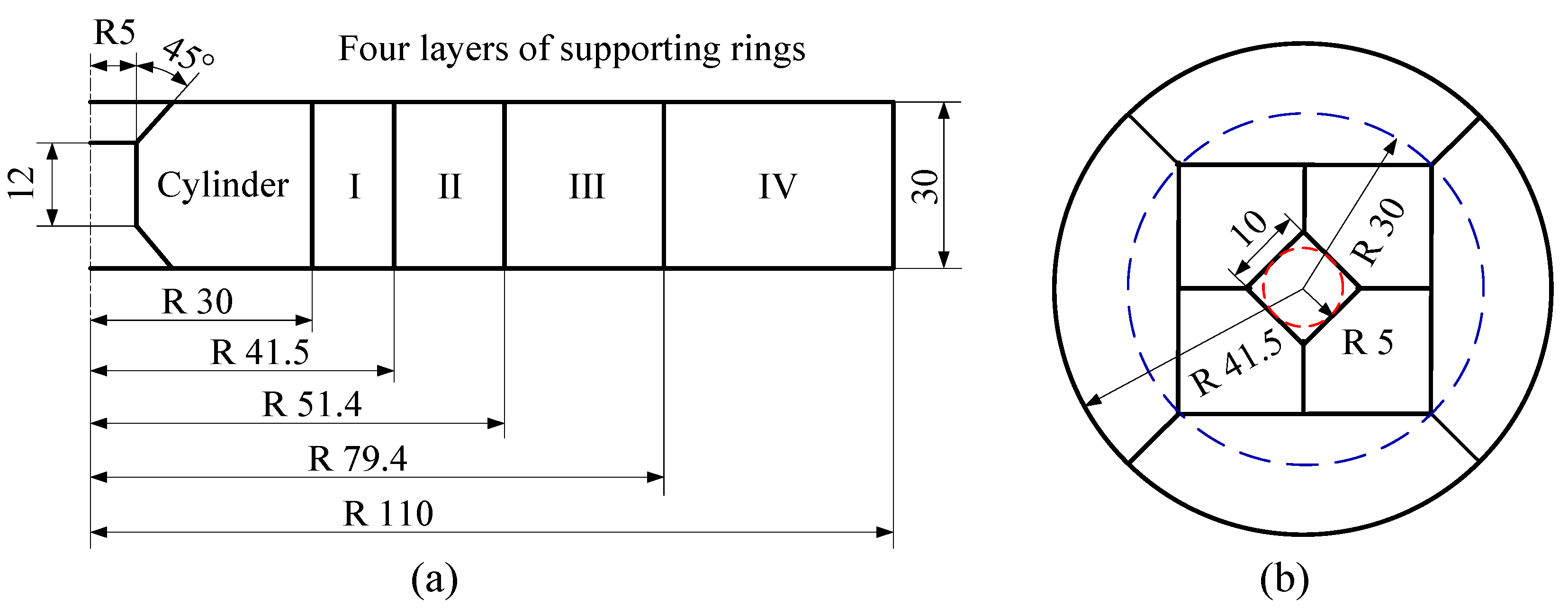
Figure 3.
Finite element model of high-pressure die (1/2).
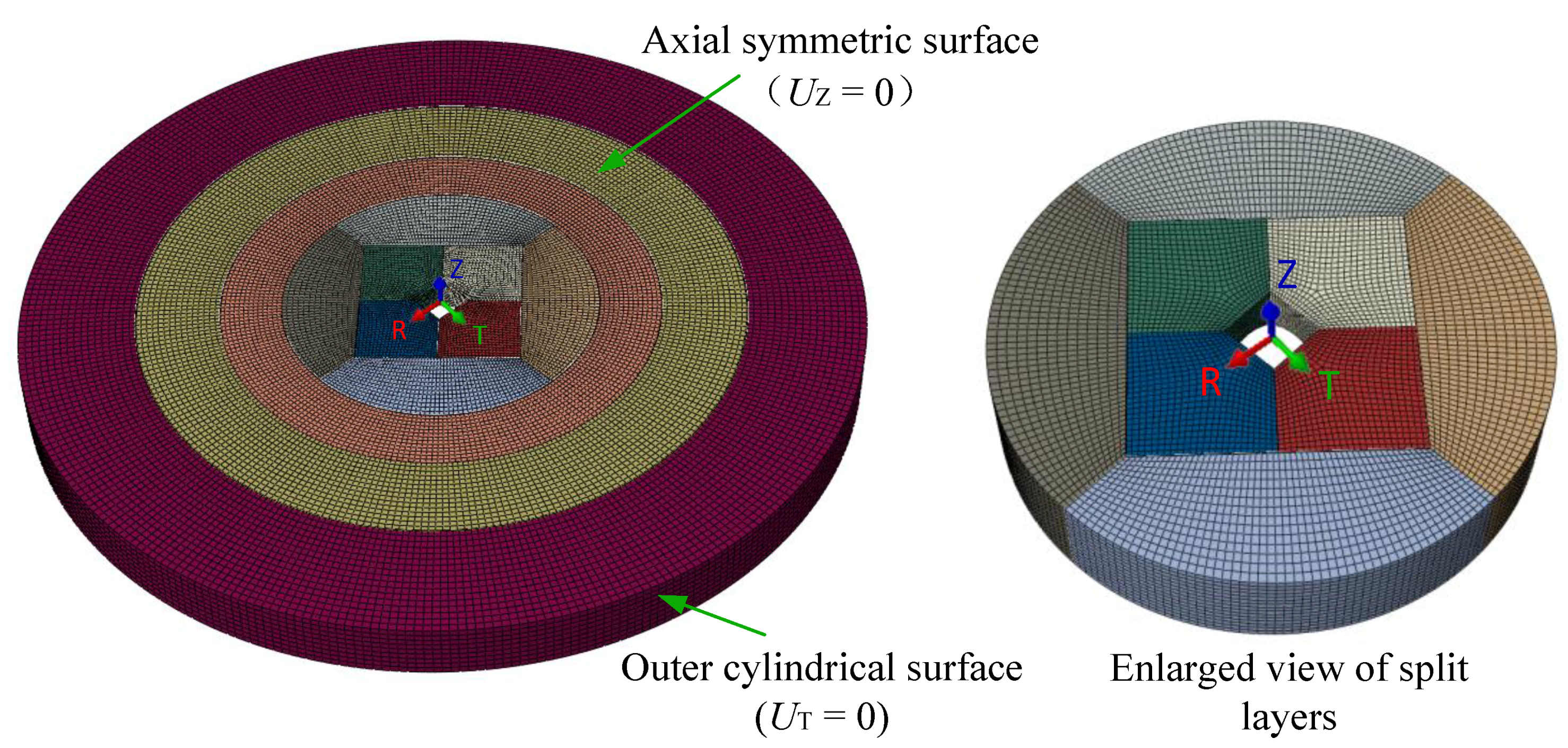
Figure 4.
Von Mises stress distributions of cylinders: (a) BTD; (b) SLSD; and (c) DLSD.

Figure 5.
Von Mises stress distributions of first layer supporting rings: (a) BTD; (b) SLSD; and (c) DLSD.
Figure 5.
Von Mises stress distributions of first layer supporting rings: (a) BTD; (b) SLSD; and (c) DLSD.

Figure 6.
Principal stress distributions of cylinders: (a) BTD; and (b) DLSD.

Figure 7.
Principal stress distributions of first layer supporting rings: (a) BTD; and (b) DLSD.
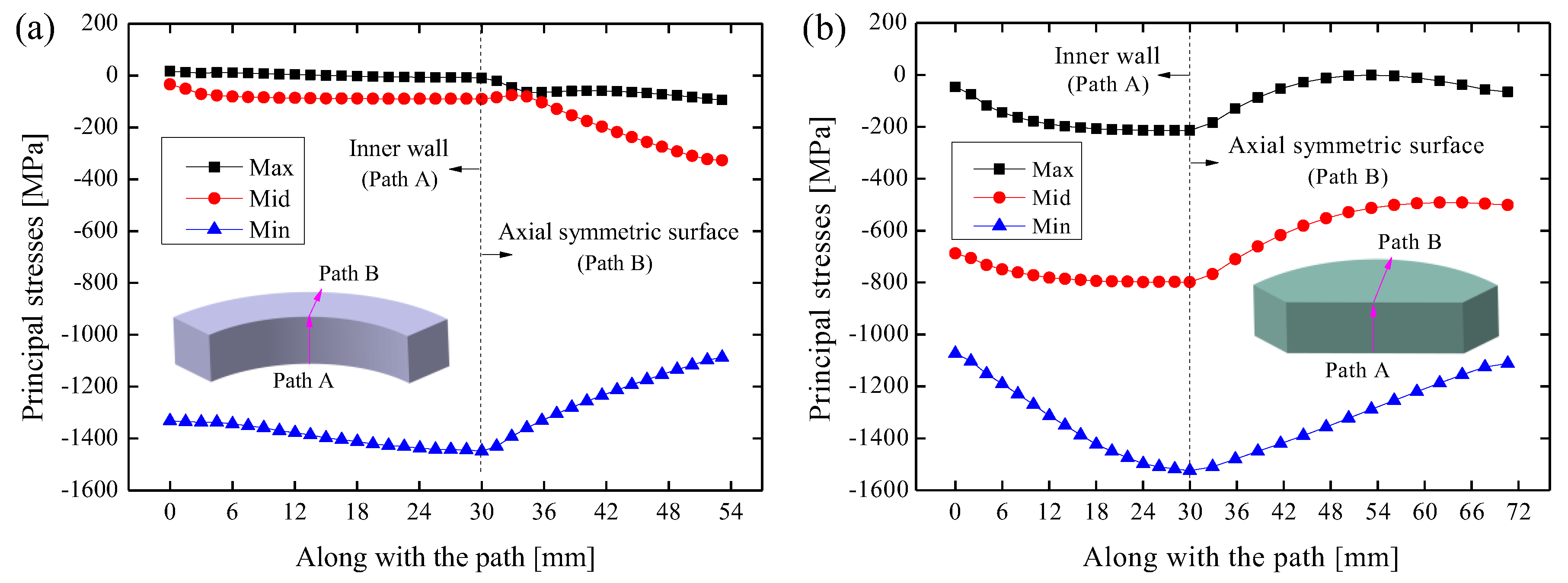
Figure 8.
Configurations of the split layer in DLSD with 4, 6, 8 and 10 split blocks.
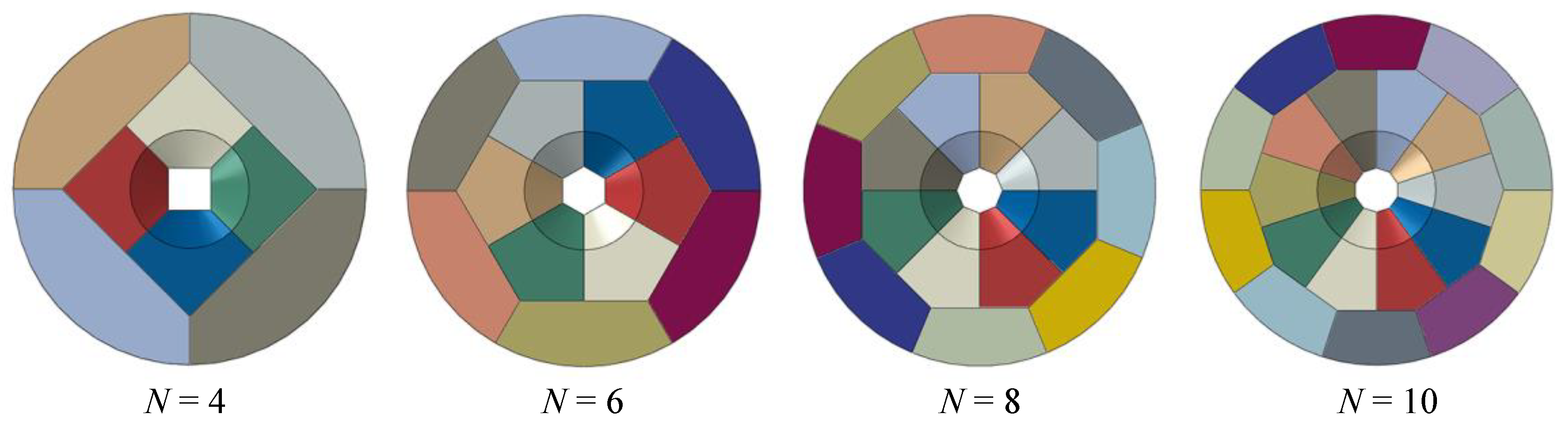
Figure 9.
Magnitudes of von Mises stress on the cylinders with different numbers of split blocks.

Figure 10.
Magnitudes of von Mises stress on the first layer supporting rings with different numbers of split blocks.
Figure 10.
Magnitudes of von Mises stress on the first layer supporting rings with different numbers of split blocks.

Figure 11.
Relationships of pressure-bearing capacity with the number of split blocks.
Figure 12.
Assembled BTD and DLSD with 4 and 8 split blocks as well as the corresponding cracked cylinders.
Figure 12.
Assembled BTD and DLSD with 4 and 8 split blocks as well as the corresponding cracked cylinders.


Table 1.
Material parameters of tungsten carbide cylinder and alloy steel supporting rings.
| Material | Density (g/cm3) | Young’s Modulus (GPa) | Poisson’s Ratio | Failure Strength (MPa) |
|---|---|---|---|---|
| Tungsten carbide | 14.6 | 578 | 0.21 | 6200 |
| Alloy steel | 7.83 | 210 | 0.29 | 1330 |
© 2018 by the authors. Licensee MDPI, Basel, Switzerland. This article is an open access article distributed under the terms and conditions of the Creative Commons Attribution (CC BY) license (http://creativecommons.org/licenses/by/4.0/).
Share and Cite
MDPI and ACS Style
Yi, Z.; Fu, W.; Li, M.; Zhao, L.; Wang, L.; Li, R. Strength Analysis of a Novel High-Pressure Die with Double-Layered Split Structure. Metals 2018, 8, 606. https://doi.org/10.3390/met8080606
AMA Style
Yi Z, Fu W, Li M, Zhao L, Wang L, Li R. Strength Analysis of a Novel High-Pressure Die with Double-Layered Split Structure. Metals. 2018; 8(8):606. https://doi.org/10.3390/met8080606
Chicago/Turabian StyleYi, Zhuo, Wenzhi Fu, Mingzhe Li, Liang Zhao, Liyan Wang, and Rui Li. 2018. "Strength Analysis of a Novel High-Pressure Die with Double-Layered Split Structure" Metals 8, no. 8: 606. https://doi.org/10.3390/met8080606
Note that from the first issue of 2016, this journal uses article numbers instead of page numbers. See further details here.