PCBN Performance in High Speed Finishing Turning of Inconel 718


Department of Mechanical Engineering, University Carlos III of Madrid, Avda. de la Universidad 30, Leganés, 28911 Madrid, Spain
*
Author to whom correspondence should be addressed.
Metals 2018, 8(8), 582; https://doi.org/10.3390/met8080582
Submission received: 29 June 2018
/
Revised: 23 July 2018
/
Accepted: 24 July 2018
/
Published: 26 July 2018
(This article belongs to the Special Issue Machining and Finishing of Nickel and Titanium Alloys)
Abstract
:Inconel 718 is a Ni superalloy widely used in high responsibility components requiring excellent mechanical properties at high temperature and elevated corrosion resistance. Inconel 718 is a difficult to cut material due to the elevated temperature generated during cutting, its low thermal conductivity, and the strong abrasive tool wear during cutting process. Finishing operations should ensure surface integrity of the component commonly requiring the use of hard metal tools with sharp tool edges and moderate cutting speeds. Polycrystalline cubic boron nitride (PCBN) tools recently developed an enhanced toughness suitable for these final operations. This paper focuses on the study of PCBN tools performance in finishing turning of Inconel 718. Several inserts representative of different manufacturers were tested and compared to a reference carbide tool. The evolution of tool wear, surface roughness, and cutting forces was analyzed and discussed. PCBN tools demonstrated their suitability for finishing operations, presenting reasonable removal rates and surface quality.
1. Introduction
Nickel-based superalloys with excellent mechanical properties at high temperature and corrosion resistance find a wide range of applications such as aircraft engines power-generation turbines, nuclear power generation, and chemical processes involving aggressive environments [1,2]. Surface integrity and tool wear are challenges when machining these difficult to cut materials due to strong work hardening, presence of hard carbides, and low thermal conductivity leading to high temperatures during machining [3,4,5].
Proper tool selection and definition of cutting parameters are critical in order to ensure productivity in machining processes of Ni alloys. Tool material, geometry, and coating; cooling strategy; and cutting parameters (cutting speed and feed) strongly determine tool wear evolution and surface integrity [6,7].
Extreme conditions during cutting require the use of advanced tool materials such as cemented tungsten carbides, ceramics, and cubic boron nitride (CBN) being the main cutting material families used in rough machining of Ni superalloys [8].
Carbide tools are restricted to cut in the range between 30 m/min to 70 m/min because of their poor thermochemical stability, however they can be used at high values of feed due to its toughness.
Ceramic tools based on alumina (aluminum oxide, Al2O3) and silicon nitride (Si3N4), are suitable for Ni alloy machining. Alumina combined with TiC improve thermal properties of the insert allowing the increase of cutting speed about five times higher than the carbide tools (120–240 m/min), although thermal and mechanical shock resistance are not significantly improved compared to tungsten carbides. Whisker-reinforced alumina ceramics (Al2O3 + SiCw) can reach cutting speeds in the range between 200 and 750 m/min and feed between 0.18 and 0.375 mm/rev and present improved toughness. Silicon nitride, with low thermal expansion and elevated toughness, allows machining at higher speeds and feed than alumina. Finally, cubic boron nitride (CBN) can be used to machine nickel- or boron-based superalloys with hardnesses greater than 35 HRC at cutting speeds ranging from 200 to 350 m/min [9].
Cubic boron nitride (CBN) is one of the hardest materials. Although the synthetic diamond presents higher hardness, CBN exhibits higher temperature and chemical resistance properties. This type of tool is mainly used for the rough machining of hardened alloys and cast iron.
Recently new polycrystalline cubic boron nitride (PCBN) tools have been developed and divided in to two groups, low content of CBN (40–70%) and high CBN content (80–95%). Low content of CBN has led to the development of a new generation of cutting tools exhibiting elevated hardness and enhanced toughness. The cutting edge can be sharper due to the improved toughness of PCBN tools, making them suitable for finishing operations at higher cutting speeds than carbide tools [10].
In general, PCBN tools are an appropriate choice when hard material (>50 HRC) should be machined, offering high performance in terms of good surface finishing and high manufacturing efficiency with respect to grinding processes [11,12].
PCBN tools are increasingly used in hard machining of different materials due to their excellent performance. For instance, O. Gutnichenko et al. [13,14] evaluated the tool wear and the formation of a tool protection layer (TPL) at the tool–chip interface in turning operations with high CBN content tools for different compositions of high chromium white cast irons (HCWCI) owing to elevated hardness and abrasion resistance. The increased silicon content percentage caused a reduction in forces due to the presence of a more stable TPL that reduces the vibration level and the tool wear during machining. Ling Chen et al. [15] analyzed the wear mechanisms in dry machining of HCWCI with PCBN tools, with abrasive wear being the dominant mechanism resulting in flank wear progression.
D. Boing et al. [16] focused on the cutting behavior of PCBN tools when machining different hardened steels. The lowest level of wear progression was found for steels with 50 HRC (within a tested range of 35–60 HRC). The presence of carbides in the workpiece strongly affected the tool wear evolution. The main wear mechanism was abrasion wear [17], causing crater wear resulting in final cutting edge failure. Similar wear mechanisms were observed by the authors in references [18,19] in high speed machining of hardened steel. W.Y.H. Liew et al. [20] investigated PCBN tools wear in high precision machining at low cutting speeds and demonstrated the importance of increase binder content and decrease grain size in order to improve fracture toughness of PCBN tools.
J.P. Costes et al. [21] analyzed the influence of CBN content when finishing Inconel 718. The authors found the percentages of CBN content in the range between 45% and 60% and cutting speeds between 250 m/min and 300 m/min leading to the best behavior concerning tool durability and surface quality.
C. Lahiff et al. [10] analyzed wear progression in PCBN cutting tools, main wear modes were crater and flank wear, caused by different mechanisms such as abrasion, adhesion, diffusion, and chemical wear. Flank wear is directly related to the accuracy of the dimensions of the machined part, and is usually used for tool life establishment of PCBN tools.
In a previous work of the authors [22] the viability of machining Inconel 718 with PCBN tools under dry conditions was analyzed. Elevated levels of chipping and fragile cutting edge breakages resulted from the instability produced by machining without coolant. This paper focuses on finishing turning with coolant of Inconel 718 with different PCBN tools with low content of CBN. The use of coolant influences the machining performance mainly in terms of wear progression and surface integrity of the workpiece.
As it was commented previously, different works in the literature have been focused on the use of PCBN in finishing operations on Inconel 718. Moreover, tool manufacturers are continuously developing special purpose PCBN tools for these applications. The main objective of this work is analyzing different commercial PCBN tools in order to compare their performance and establish optimal cutting parameters.
For the sake of clarity, remarkable studies regarding the use of different kind of tools for the machining of Inconel 718 are summarized in Table 1.
The results in terms of tool life, roughness, and cutting forces were compared with carbide tools used as a reference case, as the most common type tool used in finish turning of Inconel 718. The analysis of this results shows the suitability and the influence of main tool characteristics of PCBN tools for finishing operations of Inconel.
2. Experimental Set Up
2.1. Working Material and Cutting Tools
The workpiece was a cylinder with diameter 100 mm of superalloy Inconel 718, hardened by solution heat treatment and aged, obtaining an homogeneous hardness throughout the thickness of the bar of 44–45.5 HRc [22].
Five different industrial cutting tools have been considered, in order to test different materials, coatings, and cutting edge configurations suitable for finishing Inconel 718 using soluble oil as coolant. The cutting tools were provided from main manufacturers in industry, and they are representative of the recommended tools for finishing operations of Ni alloys. A conventional tool representative of the carbide family commonly used in industry-hard metal tool with TiN coating from the manufacturer Seco (TS2000 grade)-has been tested as a reference using conventional cutting speeds (50–70 m/min) [26].
Seco CBN170 grade tool (low CBN content) recommended for finishing Inconel 718 at high speed (higher than 200 m/min) was analyzed. Other PCBN grades; KB5625 (Kennametal), MB8025 (Mitsubishi), and 7015 (Sandvik); have been included in this study. The tool KB5625 was coated with TiAlN while the tool 7015 was coated with TiN, in both cases the coating was applied in a thin layer with reduced influence during machining process (these coatings got removed from the tool–workpiece interface on the first instants of the tests). Although these PCBN grades are not specifically recommended for finishing turning of Inconel 718 (mainly recommended for hardened alloys), they are similar to CBN170 grade (sharp cutting edge and low CBN content) and in some cases they are currently being used for this machining operation in industry [22,26].
The main characteristics of the tools analyzed in this work are summarized in Table 2.
As indicated, the reason for testing a coated carbide tool is to have a machining reference under the conventionally used conditions for the finishing turning of Inconel 718. The obtained results will be used to assess the interest of using PCBN tools in these processes. Therefore, the recommended value of the nose radius for finishing turning of Inconel 718 is 0.4 mm for the carbide tool and 0.8 mm for PCBN tools (it is recommended to use higher tip radius for PCBN tools due to its lower toughness). The coating and cutting edge configuration was stated by the manufacturer in order to obtain the best cutting performance.
Seco carbide insert (TS2000 grade with the code CCMT 09T304F1) recommended for finishing operations of nickel-based superalloys, was attached to a tool holder with the code 2525M09JET with resultant positive rake angle of 17° and a clearance angle of 7°. The tool tip presented a radius of 0.4 mm and tip angle of 80° cutting edge radius of 25 µm.
Similar geometry was stated for the PCBN tools, just differencing in the cutting edge preparation (see Table 2). The inserts with CNGA120408 code were attached to a tool holder PCLNR2525M12 resulting in an effective rake angle of −6° and a clearance angle of 6° with a tip radius of 0.8 mm and a tip angle of 80°.
2.2. Instrumentation and Set-Up
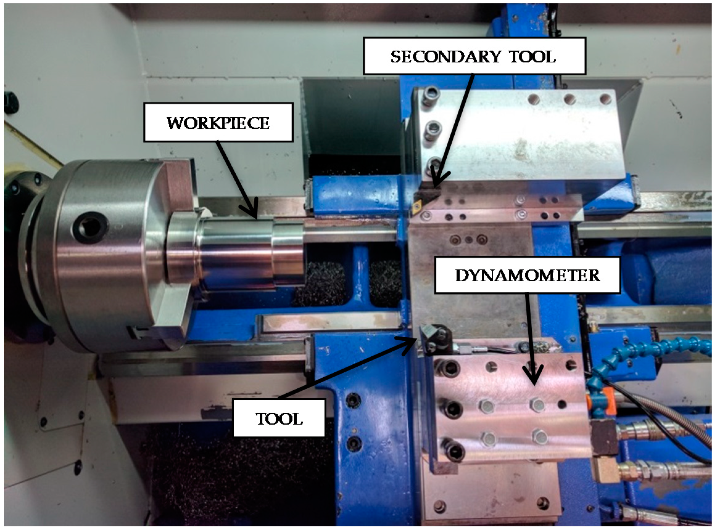
Experiments were carried out in a CNC lathe Pinacho Smart turn 6/165 (Pinacho, Huesca, Spain) instrumented with a dynamometer Kistler 9257B (Kistler, Winterthur, Switzerland) for cutting forces measurement (see Figure 1)
Surface quality was evaluated using a surface roughness tester Mitutoyo model SJ-201 (Mitutoyo, Tokyo, Japan).
Since cutting edge geometry of the tools strongly influences finishing operation in Inconel 718 [24] initial geometry of fresh inserts and wear progression were analyzed using an Optika SZR (Optika, Ponteranica, Italy) microscope and scanning electron microscopy (SEM), Philips XL-30 (Philips, Amsterdam, Netherlands) with an EDSDX4i system.
Water-soluble cutting fluid Rhenus FU50T with mixing ratio of 6% is introduced externally through a coolant hose from Smart Cooling Systems with low and high pressure allowing the control of pressure of the cutting fluid. Conventional coolant pressure of 7.5 bar was applied. Coolant is delivered through the tool holder (Duo Jetstream Tooling from Seco Tools) with the aim of ensuring the effective application at the cutting zone.
2.3. Experimental Procedure
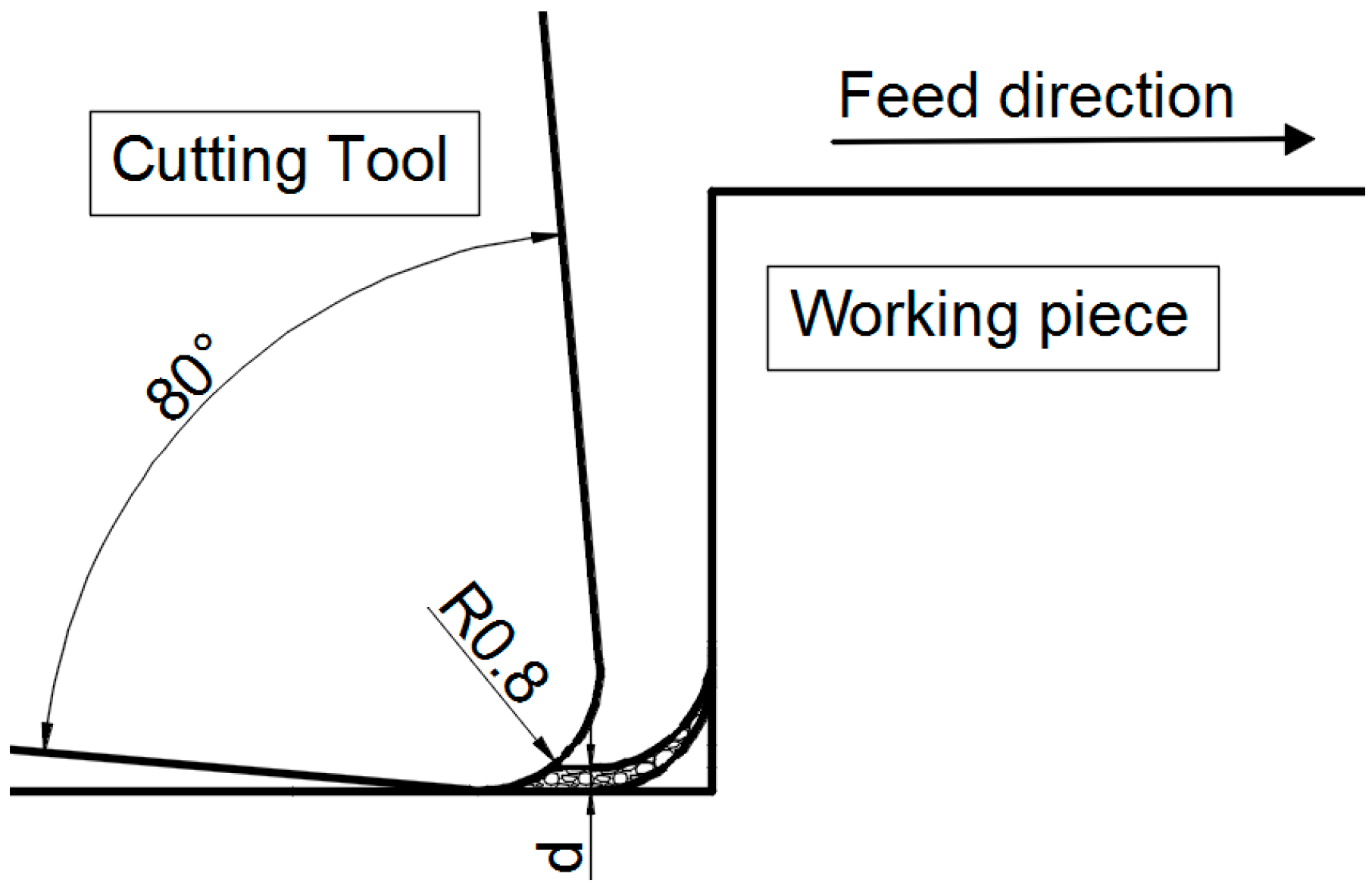
Cylinder turning tests were performed machining subsequent passes. At the end of each pass a rounded zone is generated due to the effect of tool tip radius (see Figure 2). This zone causes a sudden increment of undeformed chip cross section at the end of the following passes. Since cutting depth is small in finishing operations, significant increments of cutting forces were observed at the end of the pass affecting tool wear [22]. A secondary tool was provided in the lathe in order to remove this zone at the end of each cutting pass (see Figure 1).
Cutting forces were measured during cutting test, and testing procedure was periodically stopped in order to evaluate the machined surface roughness and tool wear progression.
Representative roughness values were obtained as the mean between nine measurements of this parameter.
Tool life criterion was established depending on the dominant wear mode observed in each tool. Thus, three different criteria were stated: flank wear or notch wear larger than 0.4 mm and catastrophic cutting edge breakage.
Different cutting parameters were defined for carbide and PCBN tools according to the recommendations provided by the tool manufacturers. Cutting parameters are summarized in Table 3, all tests were performed at the same pressure and flow of the coolant (7.5 bar and 1.2 L/min, respectively).
3. Results and Discussion
3.1. Cutting Forces
The three components of the total cutting force were measured in tests: cutting force (Fc), feed force (Ff), and back force (Fp). Each condition was tested twice obtaining variations lower than 5%; hence, mean values were chosen to perform further analysis. The specific force components (kc, kf, and kp) were calculated as the ratio between the force value and undeformed chip cross section, also the resultant force (Fr) and the resultant specific force (kr) were calculated.
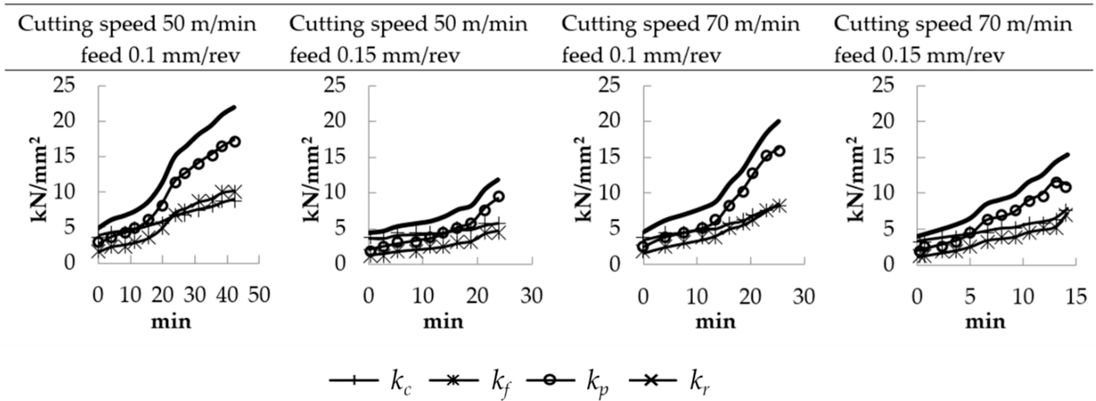
Figure 3 shows the evolution of the specific cutting forces vs. cutting time for the case of turning tests using the carbide tool TS2000 for all cutting parameters tested.
At the first stages of the test corresponding to fresh tool, values of specific cutting force (kc) between 3300 and 4600 N/mm2 were obtained. The increment of cutting speed resulted in a reduction about 10% in kc. This effect is related to the thermal softening caused by the increase of temperature at the primary and secondary zones. The increment of feed led to a decrease in all components of specific force about 20–30% because of the diminished effect of cutting edge radius that is especially significant at low values of feed.
Wear progression caused the increment of all specific force components especially in the case of kp reaching at the end of tool life, values up to 4–6 times the value for fresh tool.
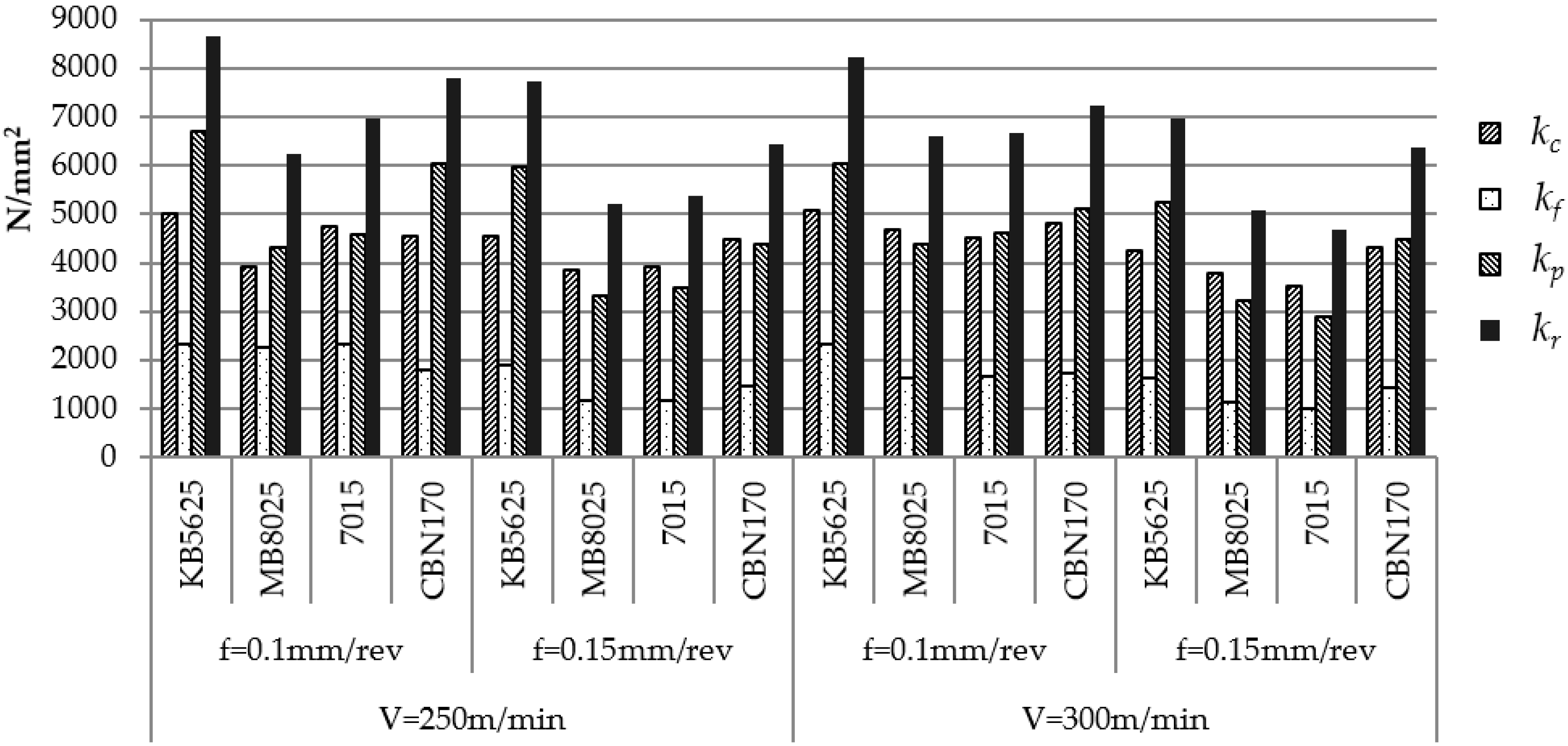
The values of specific resultant cutting force obtained with fresh PCBN tools are summarized in Figure 4. The highest values of specific force (between 6500 and 8700 N/mm2), were obtained for KB5625 and CBN170 tools. Both tools presented the same cutting edge configuration: honing with radius 25 microns. Tool MB8025 with chamfered cutting edge (50 microns) and tool 7015 with cutting edge radius of 15 microns presented values of kr between 5000 and 6500 N/mm2. The reduced specific cutting forces obtained in the case of tool 7015 were related to the value of the cutting edge radius, lower than the cutting edge radius of KB5625 and CBN170 tools. On the other hand, the specific cutting forces obtained with the tools exhibiting honing radius 25 microns (KB5625 and CBN170) are higher than those obtained with the tool MB8025 with chamfered cutting edge of 50 microns. This behavior is related to the effect of small value of the undeformed chip thickness.
Higher values of cutting velocity, as it is the case of PCBN tools when compared to reference tool, are in general related to lower values of specific cutting forces due to thermal softening. However, in the tests carried out in the present work, the specific cutting forces were higher in all PCBN tools analyzed due to the negative rake angle in these inserts. Moreover, the depth of cut was also lower and thus the mean uncut chip thickness is also lower. In these conditions of low values of chip thickness over cutting edge radius ratio, the cutting edge plays the role of the rake surface leading to an effective negative local rake angle [9] inducing high values of specific cutting forces. As it was commented before, the differences in cutting parameters used in the case of PCBN and hard metal tools explain the differences in specific cutting forces.
The influence of cutting parameters on specific cutting forces in the tests carried out with fresh PCBN inserts showed similar trend to that described for the carbide tool.
Cutting speed increment led to moderate decrease of kr up to 10%. The effect of feed is more significant with increments of kr up to 15% to 40% when the feed is reduced. As it was commented previously, the small value of undeformed chip section enhances the effect of the tool tip geometry causing a general increase of specific components of the force.
The evolution of the three components of the force was also measured for each tool in all cutting parameters. The curves showed in Figure 5 present similar trends in most cases. The back force increased significantly with wear progression due to flank wear and chipping observed in the tool.
The increment of back force was more elevated that that observed in carbide tool with values of specific force 5–8 times higher than the values measured for fresh tool. Flank wear, being the dominant mode observed in PCBN tools, does not affect the cutting edge geometry.
The increase of the specific force kp in the case of PCBN tools is mainly related to the ploughing force. This force is related to the flow of work material ploughed by the clearance face of the tool due to the elastic deformation of the workpiece material under the clearance surface. As the flank wear evolves, the ploughing force increases. Monitoring the evolution of this force can give relevant information on the stage of tool wear evolution.
The specific forces could be adjusted to a straight line in most cases. In some of the tests, as tool wear progresses the force enhancement is more pronounced, see Figure 5. This effect may be explained by the impact of less significative but also present wears on the cutting edge (mainly notch wear).
In all cases, the resultant specific force was really elevated, reaching values of kr up to 20,000–25,000 with feed 0.15 mm/rev increasing up to 40,000 N/mm2 with feed 0.1 mm/rev. In all cutting parameters, the tool PCBN 7015 caused the lowest specific cutting forces at the end of tool life with values about 2.8–3.5 the value at the initial stage of cutting process.
Although the tool MB8025 also presented moderate values of specific force at the beginning of the test, the increment of kr with wear progression was much more accute reaching values of kr 4–5 times the value obtained with fresh tool. In general, this tool reached the largest resultant specific cutting forces for all conditions.
For all cutting parameters, the tools with a cutting edge radius equal to 25 µm (KB5625 and CBN170) presented similar resultant specific force at the beginning of the test and at the end of the tool life. However, the values found for this tools at the end of their life are in-between those found for PCBN 7015 and MB8025.
3.2. Tool Wear and Tool Life
As it was explained previously, the tests were performed also with carbide insert with the aim of obtaining reference cases representatives of current finishing operations in industry. In previous works developed by the authors, a systematic and broader analysis of tool wear can be found for this type of cutting process both with coolant and in dry conditions [22,23].
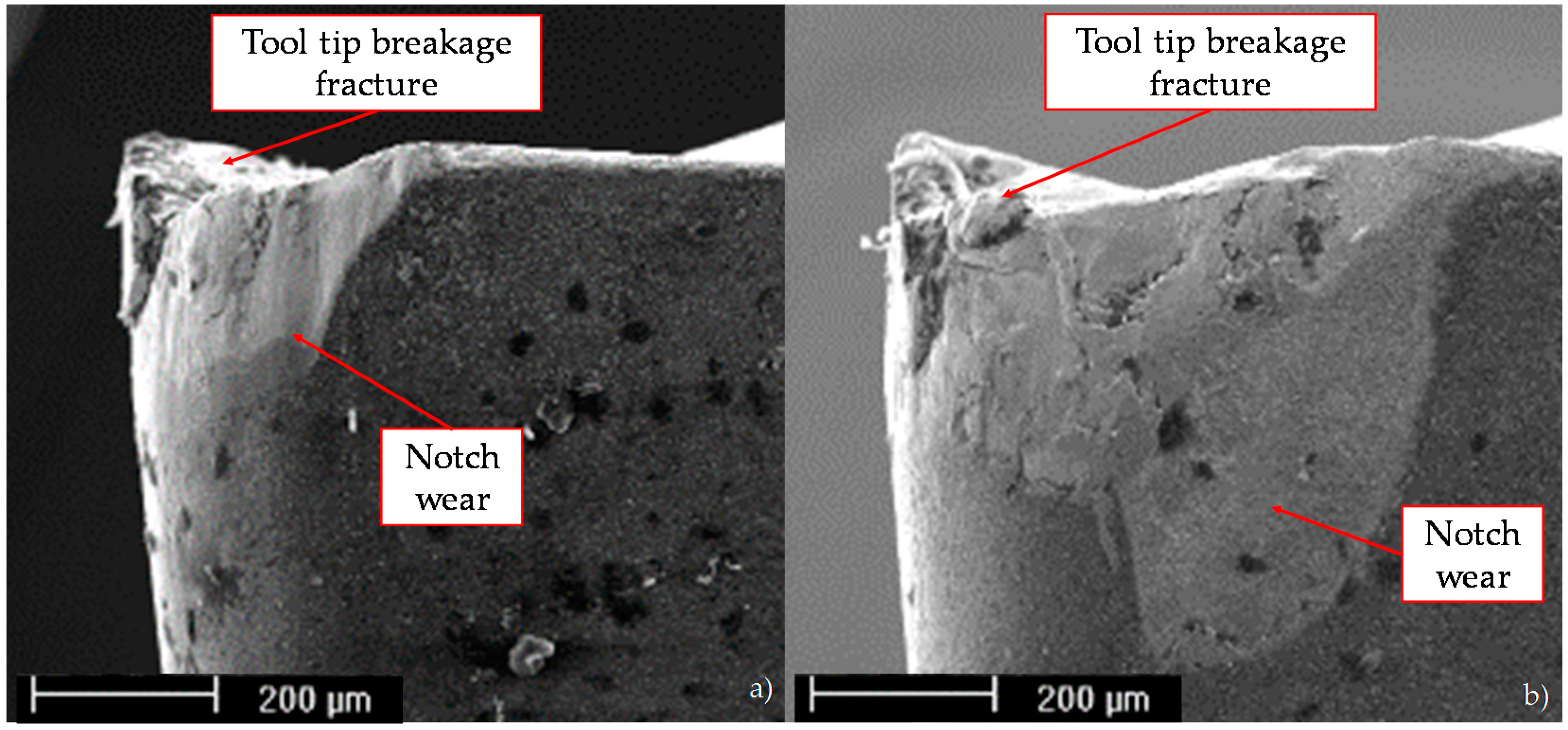
At the beginning of the tests, the initiation of different wear mechanisms was observed: chipping (breakage located along the cutting edge affecting the rake and relief surfaces), notch wear (wear type located at the depth of the cut line affecting the rake and relief surfaces, associated with the strain hardening of the workpiece material and the pressure welding of chips), flank wear (type of wear located at the relief surface, due to erosion of the tool material in the interface with the workpiece), and built up edge (type of wear created by pressure welding of the chip) [27,28]. During first stages of cutting process, in all carbide tools tested, notch was the predominant wear. The notch increased progressively up a characteristic length about 0.2 millimeters being difficult to be identified due to the adhesion of material. Fragile fractures were not easily identified because of the material adhesion at the cutting edge; however, their onset at the edge progressively led to loss of the initial geometry. Wear progressed, evolving to chipping. Finally, the catastrophic breakage of the tool tip due to chipping caused the end of life of these tools as can be appreciated in Figure 6.
Despite the differences in cutting edge configuration, coating, and PCBN similar wear mechanisms and progression were observed for all PCBN tools analyzed.
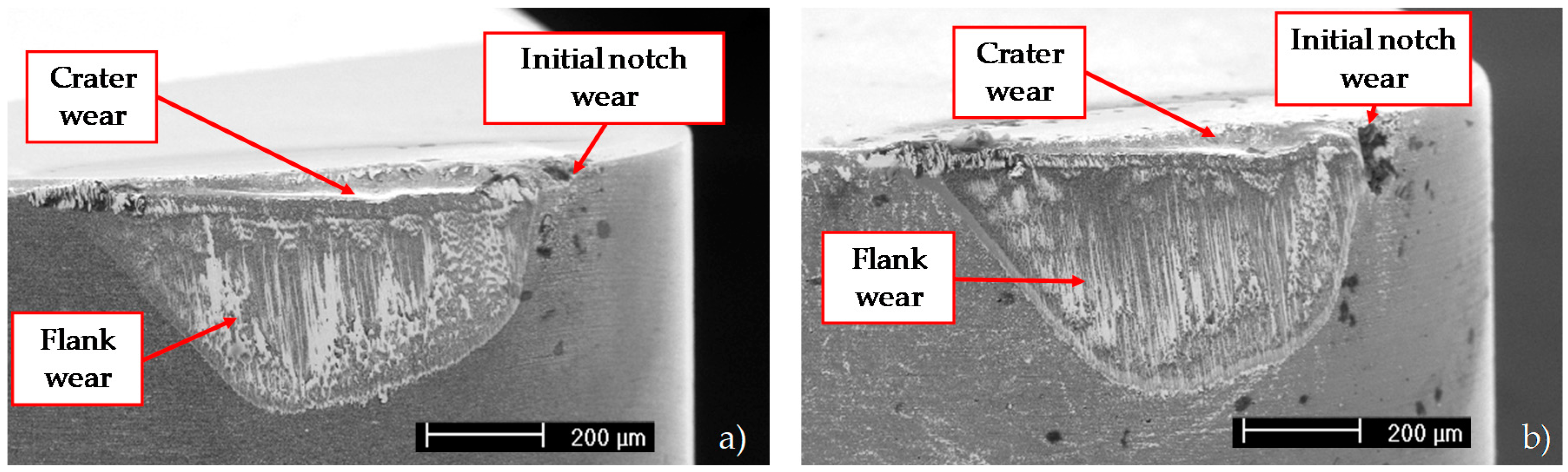
At the beginning of cutting, the initiation of different wear patterns—mainly flank, built up edge, moderate chipping, and an almost neglectable notch wear—were observed. With the evolution of the process (cutting time about five minutes) also crater wear onset was identified in the rake surface. Chipping and initial notch wear appearing at the first stages of cutting time did not progress significantly and these worn zones were almost polished by abrasive wear (these kinds of wear have been identified by tool manufacturers in similar machining processes [29]). Despite the occurrence of different wear mechanisms, the dominant wear mode for PCBN tools was flank wear in all conditions. End of life criterion were stated for flank length equal to 0.4 mm (this value was previously used by the authors in different works [22,24]. Figure 7 shows SEM images of tools MB8025 and 7015 at the end of life illustrating the prevalence of flank wear. Although notch and crater wear are also identified in the images, the extension of worn zones due to these mechanisms are not significant when compared to flank extension.
The chip morphology depends on the level of tool wear, being an indicator of wear progression. At the beginning of the process, very long chips with homogeneous morphology were observed. As wear progressed and cutting edge lost its initial geometry, the chip length diminished. Finally, at cutting time close to the end of tool life, the chips were irregularly shaped and segmented.
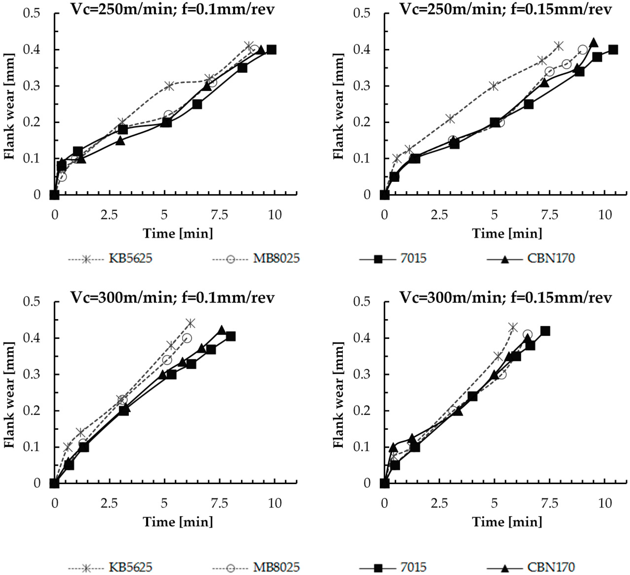
Figure 8 presents the evolution of flank wear with cutting time for PCBN tools. At the beginning of the test, a significant rate of wear occurred due to the cutting edge accommodation. With the increment of cutting time, the PCBN 7015 tool presented the best wear resistance with tool life between 4 and 12% higher than tool life for CBN170; 7.7% to 33.3% higher than tool life for MB8025 and between 11.4% and 31.6% higher than KB5625.
The tool efficiency was evaluated in terms of the machined surface per time (Smach.t) and the machined surface per cutting edge (Sedge) defined in Equations (1) and (2) respectively:
where:
- Smach.t: machined surface per unit time (mm2/s)
- Sedge: machined surface per edge (mm2)
- Vc: cutting speed (m/min)
- f: feed (mm/rev)
- T: tool life (min)
Table 4 summarizes the values obtained for tool lives, machined surface per unit time and machined surface per cutting edge for carbide and PCBN tools.
As expected, both carbide and PCBN tools presented higher tool life at lower cutting speeds. The feed clearly influenced the tool life of carbide insert, with a reduction of about 43% for the highest value of the feed. However, the feed did not show significant effect in the case of PCBN tools. The carbide tool is used as a reference, however the tool life about 40 min is much higher than that obtained for PCBN tools, ranging from 5 to 10 min. In order to compare the machining performance of these tools in finishing operations, the machined surface per unit of time and per cutting edge were considered.
The elevated cutting velocities involved in machining with PCBN tools, led to values of machined surface per unit time between 2.5 and 6 times the value of surface machined with carbide tool at the same feed. PCBN tools exhibiting the highest durability (7015 grade) presented enhanced values of machined surface per cutting edge, between 10 and 39% higher at feed 0.1 mm and between 76 and 155% higher at feed 0.15 mm. Finally, the cost per edge of the PCBN tools, about 10 times higher than that of the carbide tools, should be taken into account for process definition.
It is worth noting that the tools analyzed in this work are commercial inserts with different characteristics which make difficult decoupling the influence of different parameters in the cutting edge duration difficult.
With the tool 7015 the longest tool life was obtained, despite its theoretically less robust cutting edge. The tool 7015 presents the sharpest cutting edge, KB5625 y CBN170 also present round honing cutting edge; however, the radius is larger and MB8025 exhibits a chamfered cutting edge of 50 microns. The sharpest honing is coherent with the lower cutting forces experimentally obtained for this tool. However, the honing of this tool is not exactly rounded but elliptical and it is not completely defined with the only value provided by the manufacturer as “radius” of the honing. In addition, the larger tool life found for the tool 7015 may be explained by the effect that could have the geometrical characteristics of the honing on the toughness and also by a possible larger toughness of the grade used by the tool 7015 with respect to the rest of the tested PCBN tools. The reduced content of CBN (50% for 7015; 60% MB8025; 65% CBN170) is related to enhanced toughness leading to better resistance of the tool 7015.
Concerning the influence of cutting parameters, it was observed that the higher machined surface per cutting edge was obtained with cutting speed 250 m/min and feed 0.15 mm/rev for all the tools tested. Since the feed did not significantly affect the tool life, and the cutting speed of PCBN tools was critical in PCBN tools, an increment in cutting speed from 250 m/min to 300 m/min led to a decrease in life between 18% and 33% and therefore the decrease of surface removed per cutting edge. The reduction of cutting speed from 300 to 250 m/min increases the machined surface between 11% and 20%. However, the decrease of the feed resulted in reduced machined surface, depending on the tool and conditions a decrease between 25% and 40% was observed.
3.3. Surface Quality
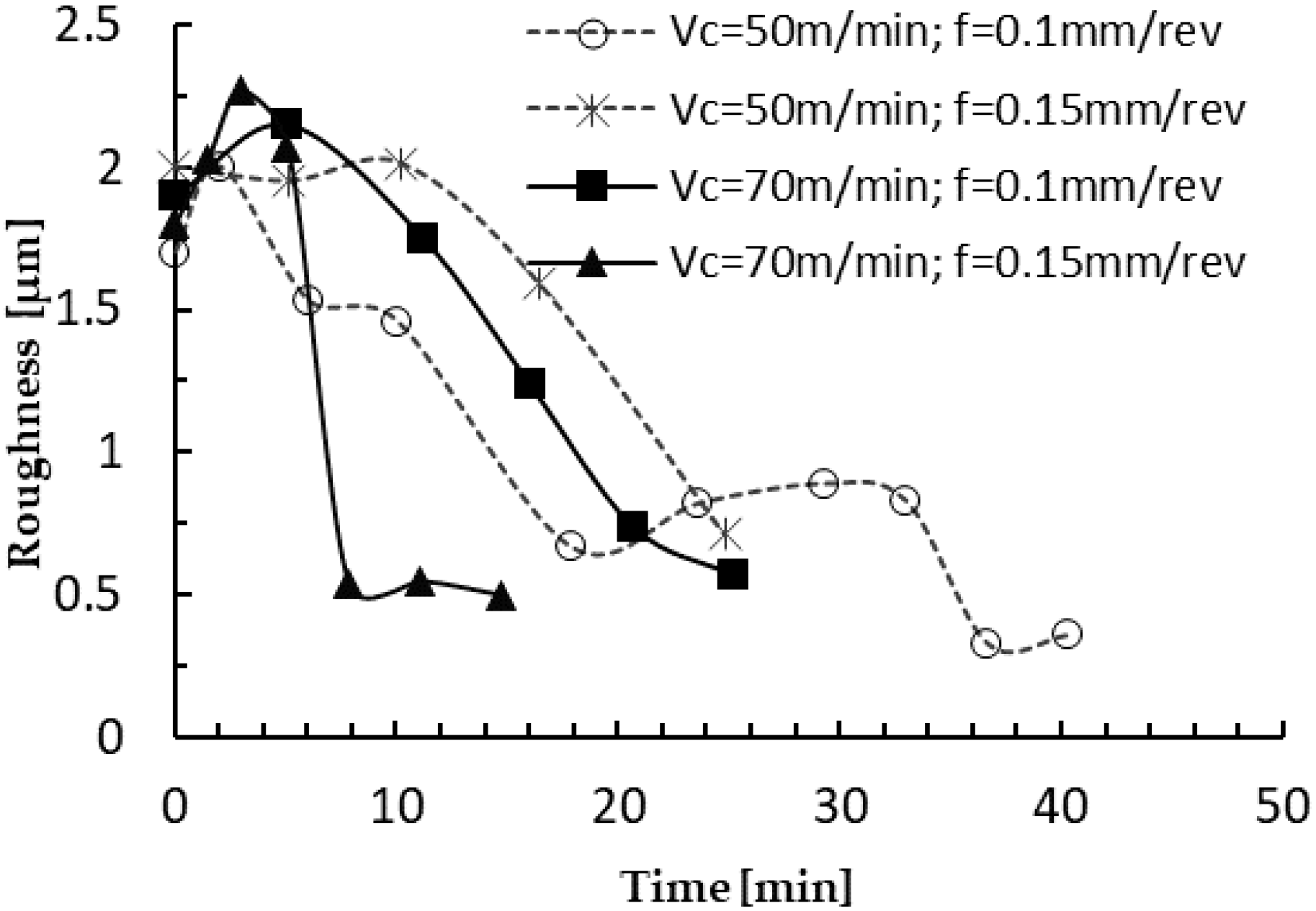
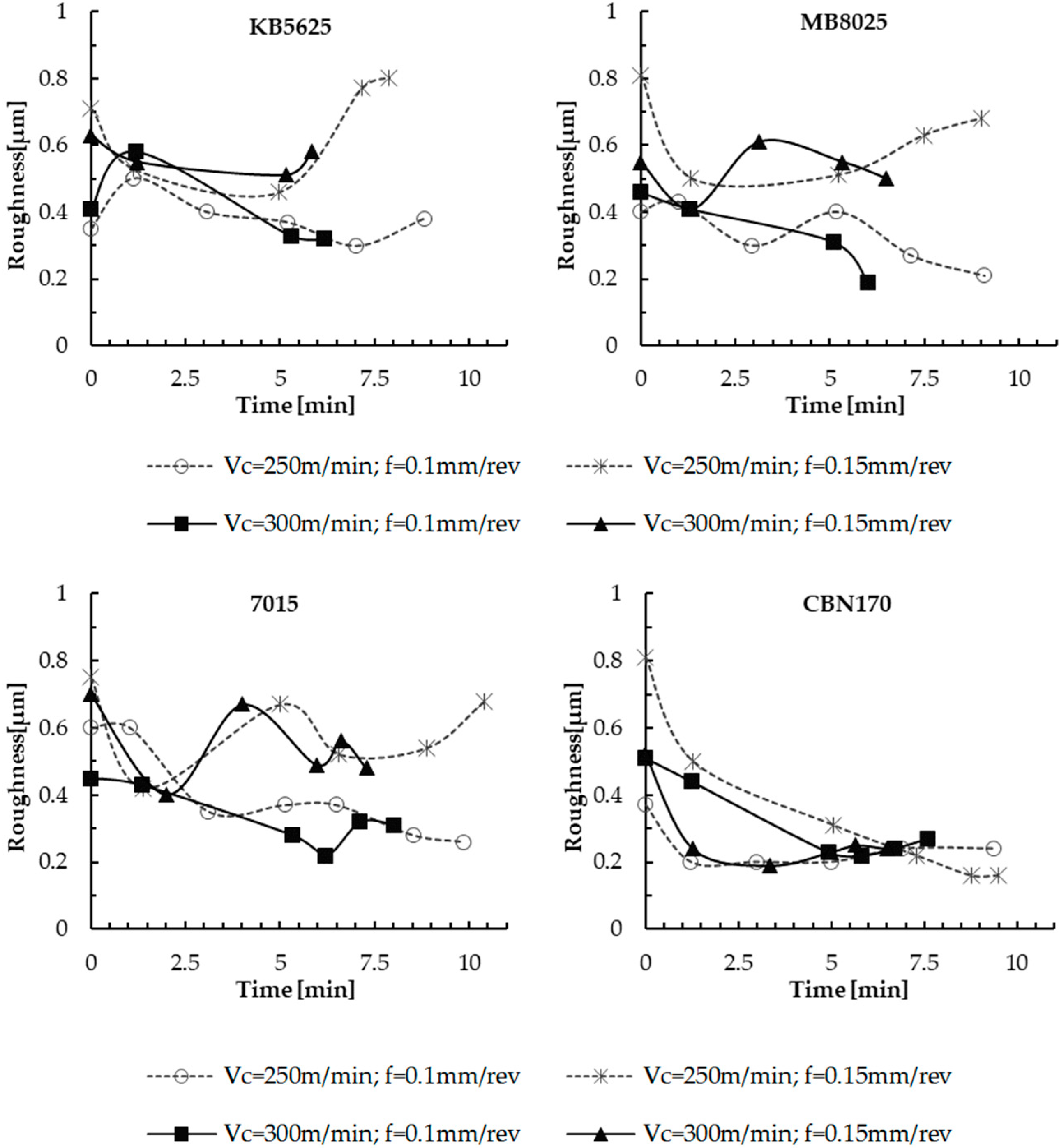
Surface quality was analyzed in terms of the arithmetic average roughness (Ra) measured at different stages of the cutting process for all cutting parameters and tools. Three measurements at three different zones presented variations lower than 5%. The values represented in the figures correspond to the maximum values obtained in the measurements and they were similar to those found by other researcher for finishing turning of Inconel 718 using carbide tools [25]. The maximum values of roughness measured in cutting tests with carbide tool and PCBN are presented in the Figure 9 and Figure 10, respectively.
All PCBN tools produced similar surface roughness, moreover neither the wear progression nor the cutting parameters significantly affected the roughness with Ra ranging between 0.2 and 0.8 in all cases tested.
The carbide tool presented different behavior with elevated values of roughness (about 2 microns) obtained with fresh tool, significantly worse than the roughness obtained with PCBN tools. The elevated depth of cut in tests with carbide tool and the tool tip radius of this tool (half of the value used in PCBN tools) are known to cause elevated roughness. The development of chipping at the tool tip as the cutting time increased resulted in an increased effective tool tip radius related to the decrease of Ra with the wear progression.
4. Conclusions
Finishing turning of Inconel 718 has been analyzed in this paper, testing commercial PCBN tools with low CBN content from different manufacturers: CBN 170 (Seco), KB5625 (Kennametal), MB8025 (Mitsubishi), and 7015 (Sandvik).
All inserts presented cutting edge configuration suitable for finishing turning: round honing with reduced radius (15–25 µm), chamfer honing (width 50 µm), and negative rake angle −6°.
The experiments with PCBN tools were carried out with coolant at high cutting speeds and compared with the results obtained with the reference carbide tools (TS2000 grade) tested at their nominal lower speed.
Main conclusions derived from analysis of tool wear progression, cutting forces, and roughness are summarized below:
Elevated specific cutting forces were obtained with all PCBN tools due to the negative cutting geometry and the reduced uncut chip thickness enhancing the effect of roundness of cutting edge.
PCBN tools MB8025 (chamfer honing of 50 µm width) and 7015 (round honing 15 µm) gave lower initial specific forces. Specific resultant cutting forces between 5000 and 6500 N/mm2 were observed. The increase of cutting speed led to a reduction in Kr about 10% due to thermal softening. The decrease of feed led to significant increments of kr ranging between 15% and 40%.
The back force kp is the most sensitive component strongly increasing with tool wear evolution. The values of kp at the end of tool life were 5–8 times the values obtained at the beginning of the process with fresh tool. Monitoring the evolution of this force can give relevant information concerning tool wear progression.
The tool PCBN 7015 originated the lowest values of specific cutting force at the end of tool life. Nevertheless, the increase of specific cutting force with wear progression was very accute with increments of kr ranging between 280% and 350%.
Different wear mechanisms—chipping, notch wear, flank wear, and built up edge—were simultaneously observed in carbide tool. Wear evolution led to final catastrophic break of the tool tip due to chipping causing the end of life. Carbide tool life was strongly reduced with the increment of cutting speed and feed.
All PCBN tools exhibited similar initial wear mechanisms: chipping, notch wear, flank wear and built up edge, and further evolution. About cutting time equal to 5 min, crater was initiated. Finally, flank wear evolved to be the dominant wear for all PCBN tools and conditions tested. The tool life criterion was stated for a flank length equal to 0.4 mm. Tool life decreased with cutting speed, however a negligible effect of feed was observed.
PCBN tool 7015 presented the largest cutting edge duration, followed by CBN170. The best cutting parameters for cutting edge duration corresponded to cutting speed equal to 250 m/min and feed 0.15 mm/rev. Costes et al. [21] demonstrated that the CBN content of the tool strongly affects the tool performance. The insert based on 45% CBN showed best behavior in finishing operations of Inconel 718. This result is in agreement with the highest duration of the tool 7015 (50% CBN), with the lowest CBN content close to 45%. The low CBN content of tool seems to be positive for tool life enhancement due to the increased toughness of this tool, reducing the evolution of chipping and notch wear.
Strong differences in tool life were observed: carbide tools presented tool life higher than 40 min, PCBN tools were worn after cutting time about 5–10 min. However, the increased cutting speed for PCBN tools allowed obtaining increased machined surface per cutting edge using PCBN tools, up to 155% higher for 7015 Grade.
Surface roughness was minor during operation of PCBN tools, with values about 0.2 and 0.8 µm even at the end of tool life. However, carbide tools provided lower surface quality in terms of roughness, with values of 2 µm with fresh tool. The progression of wear caused geometrical modification of the insert, resulting in enlarged effective tool tip radius. This effect led to diminished values of Ra.
Author Contributions
Conceptualization, J.D.-Á. and J.L.C.; Data curation, J.D.-Á. and V.C.; Formal analysis, J.D.-Á., V.C., and J.L.C.; Funding acquisition, H.M. and J.L.C.; Investigation, J.D.-Á. and V.C.; Project administration, H.M. and J.L.C.; Resources, J.L.C.; Supervision, H.M. and J.L.C.; Validation, J.D.-Á., V.C., H.M., and J.L.C.; Visualization, V.C.; Writing–original draft, J.D.-Á. and V.C.; Writing–review & editing, J.D.-Á., H.M., and J.L.C.
Funding
This research was funded by Ministry of Economy, Industry and Competitiveness and FEDER program grant number DPI2014-56137-C2-2-R.
Conflicts of Interest
The authors declare no conflict of interest.
Abbreviations
| ae | radial depth |
| ap | axial depth |
| CBN | cubic boron nitride |
| d | depth of pass |
| f | feed rate |
| Fc | cutting force |
| Ff | feed force |
| Fp | back force |
| Fr | resultant force |
| kc | specific cutting force |
| kf | specific feed force |
| kp | specific back force |
| kr | specific resultant force |
| PCBN | polycrystalline cubic boron nitride |
| SEM | scanning electron microscopy |
| Smach.t | machined surface per unit time |
| Sedge | machined surface per cutting edge |
| T | tool life |
| Vc | cutting speed |
| Ra | arithmetic average roughness |
References
- López De Lacalle, L.N.; Urbicain Pelayo, G.; Fernández-Valdivielso, A.; Alvarez, A.; González, H. Wear-dependent specific coefficients in a mechanistic model for turning of nickel-based superalloy with ceramic tools. Open Eng. 2017, 7, 175–184. [Google Scholar] [CrossRef] [Green Version]
- Jie, L. The formation and effect of interlayer gap in dry drilling of stacked metal materials. Int. J. Adv. Manuf. Technol. 2013, 69, 1263–1272. [Google Scholar] [CrossRef]
- González, H.; Calleja, A.; Pereira, O.; Ortega, N.; López de Lacalle, L.; Barton, M. Super Abrasive Machining of Integral Rotary Components Using Grinding Flank Tools. Metals 2018, 8, 24. [Google Scholar] [CrossRef]
- Ezugwu, E.O. Key improvements in the machining of difficult-to-cut aerospace superalloys. Int. J. Mach. Tools Manuf. 2005, 45, 1353–1367. [Google Scholar] [CrossRef]
- Polvorosa, R.; Suárez, A.; de Lacalle, L.N.L.; Cerrillo, I.; Wretland, A.; Veiga, F. Tool wear on nickel alloys with different coolant pressures: Comparison of Alloy 718 and Waspaloy. J. Manuf. Process. 2017, 26, 44–56. [Google Scholar] [CrossRef]
- López de lacalle, L.; Pérez, J.; Llorente, J.; Sánchez, J. Advanced cutting conditions for the milling of aeronautical alloys. J. Mater. Process. Technol. 2000, 100, 1–11. [Google Scholar] [CrossRef]
- Donachie, M.J. Superalloys: A Technical Guide, 2nd ed.; ASM International: New York, NY, USA, 2002; pp. 1–409. [Google Scholar]
- Arun Kumar, S.; Yoganath, V.G.; Krishna, P. Machinability of Hardened Alloy Steel using Cryogenic Machining. Mater. Today Proc. 2018, 5, 8159–8167. [Google Scholar] [CrossRef]
- Bushlya, V.; Zhou, J.; Avdovic, P.; Ståhl, J.E. Performance and wear mechanisms of whisker-reinforced alumina, coated and uncoated PCBN tools when high-speed turning aged Inconel 718. Int. J. Adv. Manuf. Technol. 2013, 66, 2013–2021. [Google Scholar] [CrossRef]
- Lahiff, C.; Gordon, S.; Phelan, P. PCBN tool wear modes and mechanisms in finish hard turning. Robot. Comput. Integr. Manuf. 2007, 23, 638–644. [Google Scholar] [CrossRef]
- Dahyabhai, V.; Anishkumar, P.; Gandhi, H. Analytical and Empirical Modeling of Wear and Forces of CBN Tool in Hard Turning—A Review. J. Inst. Eng. Ser. C 2016. [Google Scholar] [CrossRef]
- Sobiyi, K.; Sigalas, I. High-speed machining of martensitic stainless steel using PcBN. J. Superhard Mater. 2016, 38, 34–39. [Google Scholar] [CrossRef] [Green Version]
- Gutnichenko, O.; Bushlya, V.; Zhou, J.M.; Stahl, J.-E. Tool Wear and Vibrations Generated When Turning High-chromium White Cast Iron with pCBN Tools. Procedia CIRP 2016, 46, 285–289. [Google Scholar] [CrossRef]
- Gutnichenko, O.; Bushlya, V.; Zhou, J.; Ståhl, J.-E. Tool wear and machining dynamics when turning high chromium white cast iron with pcBN tools. Wear 2017, 390–391, 253–269. [Google Scholar] [CrossRef]
- Chen, L.; Stahl, J.-E.; Zhao, W.; Zhou, J. Assessment on abrasiveness of high chromium cast iron material on the wear performance of PCBN cutting tools in dry machining. J. Mater. Process. Technol. 2018, 255, 110–120. [Google Scholar] [CrossRef]
- Boing, D.; Schroeter, R.B.; de Oliveira, A.J. Three-dimensional wear parameters and wear mechanisms in turning hardened steels with PCBN tools. Wear 2018, 398–399, 69–78. [Google Scholar] [CrossRef]
- Poulachon, G.; Moisan, A.; Jawahir, I.S. Tool-wear mechanisms in hard turning with polycrystalline cubic boron nitride tools. Wear 2001, 250–251, 576–586. [Google Scholar] [CrossRef]
- M’Saoubi, R.; Johansson, M.P.; Andersson, J.M. Wear mechanisms of PVD-coated PCBN cutting tools. Wear 2013, 302, 1219–1229. [Google Scholar] [CrossRef]
- Ånmark, N.; Björk, T.; Ganea, A.; Ölund, P.; Hogmark, S.; Karasev, A.; Jönsson, P.G. The effect of inclusion composition on tool wear in hard part turning using PCBN cutting tools. Wear 2015, 334–335, 13–22. [Google Scholar] [CrossRef]
- Liew, W.Y.H.; Ngoi, B.K.A.; Lu, Y.G. Wear characteristics of PCBN tools in the ultra-precision machining of stainless steel at low speeds. Wear 2003, 254, 265–277. [Google Scholar] [CrossRef]
- Costes, J.P.; Guillet, Y.; Poulachon, G.; Dessoly, M. Tool-life and wear mechanisms of CBN tools in machining of Inconel 718. Int. J. Mach. Tools Manuf. 2007, 47, 1081–1087. [Google Scholar] [CrossRef] [Green Version]
- Cantero, J.; Díaz-Álvarez, J.; Infante-García, D.; Rodríguez, M.; Criado, V. High Speed Finish Turning of Inconel 718 Using PCBN Tools under Dry Conditions. Metals 2018, 8, 192. [Google Scholar] [CrossRef]
- Bushlya, V.; Zhou, J.; Ståhl, J.E. Effect of cutting conditions on machinability of superalloy inconel 718 during high speed turning with coated and uncoated PCBN tools. Procedia CIRP 2012, 3, 370–375. [Google Scholar] [CrossRef]
- Cantero, J.L.; Díaz-Álvarez, J.; Miguélez, M.H.; Marín, N.C. Analysis of tool wear patterns in finishing turning of Inconel 718. Wear 2013, 297. [Google Scholar] [CrossRef] [Green Version]
- Fernández-Valdivielso, A.; López de Lacalle, L.N.; Urbikain, G.; Rodriguez, A. Detecting the key geometrical features and grades of carbide inserts for the turning of nickel-based alloys concerning surface integrity. Proc. Inst. Mech. Eng. Part C J. Mech. Eng. Sci. 2016, 230, 3725–3742. [Google Scholar] [CrossRef]
- Download Center|Secotools.com. Available online: https://www.secotools.com/#article/81837 (accessed on 17 July 2018).
- Suárez, A.; López de Lacalle, L.N.; Polvorosa, R.; Veiga, F.; Wretland, A. Effects of high-pressure cooling on the wear patterns on turning inserts used on alloy IN718. Mater. Manuf. Process. 2017, 32, 678–686. [Google Scholar] [CrossRef]
- Cutting Tool Wear—Wear on Cutting Edges. Available online: https://www.sandvik.coromant.com/en-gb/knowledge/materials/cutting_tool_materials/wear_on_cutting_edges/pages/default.aspx (accessed on 22 July 2018).
- Seco Advanced Material Expert: Tool Wear in Finish Hard Turning. Available online: http://cbnexpert.blogspot.com/2015/12/tool-wear-in-finish-hard-turning.html (accessed on 22 July 2018).
Figure 1.
Instrumentation and disposal of experimental tests.

Figure 2.
Undeformed chip cross section increment at the end of each pass.

Figure 3.
Evolution of the cutting forces for the carbide tool.

Figure 4.
Initial specific cutting forces for the PCBN tools.

Figure 5.
Evolution of the specific cutting forces (kN/mm2) for the carbide tools.

Figure 6.
SEM image of carbide tool and the end of tool life (a) Vc = 50 m/min, f = 0.1 mm/rev (b) Vc = 70 m/min, f = 0.15 mm/rev.
Figure 6.
SEM image of carbide tool and the end of tool life (a) Vc = 50 m/min, f = 0.1 mm/rev (b) Vc = 70 m/min, f = 0.15 mm/rev.

Figure 7.
SEM image of PCBN tools at the end of tool life condition. (a) Tool grade MB8025, Vc = 250 m/min, f = 0.1 mm/rev, d = 0.15 mm; (b) tool grade 7015, Vc = 300 m/min, f = 0.1 mm/rev, d = 0.15 mm.
Figure 7.
SEM image of PCBN tools at the end of tool life condition. (a) Tool grade MB8025, Vc = 250 m/min, f = 0.1 mm/rev, d = 0.15 mm; (b) tool grade 7015, Vc = 300 m/min, f = 0.1 mm/rev, d = 0.15 mm.

Figure 8.
Evolution of the flank wear.

Figure 9.
Average roughness (µm) in carbide tools.

Figure 10.
Average Roughness (µm) in PCBN tools.


Table 1.
Summary of the most common type of tool used to machine Inconel 718.
| Process & Ref. | Tool Type | Cutting Parameters | Comments |
|---|---|---|---|
| Milling [3] | Carbide tool coated with AlTiN |
Coolant was used Vc = 20 m/min Feed per tooth: 0.03 mm/tooth ap = 5 mm ae = 16 mm | Comparison of conventional milling process and super abrasive milling (SAM) was performed. Better results were obtained for SAM than for conventional milling. |
| Carbide tool coated with TiN/TiAlN | Coolant was used Vc = 20 m/min Feed per tooth: 0.03 mm/tooth ap = 20 mm ae = 0.2 mm | ||
| PCBN grinding tool | Coolant was used Vc = 900 m/min Feed per tooth: 45–500 mm/min ap = 20 mm ae = 0.2 mm | ||
| Milling [6] | Hard metal solid mill | Coolant was used Vc = (from 11 to 140) m/min Feed per tooth: (from 0.04 to 0.15) mm/tooth | Flank and notch wear was found. |
| Turning [1] | Ceramic tool with silicon-carbide whisker added to alumina (Al2O3 + SiC) | Dry condition: Vc = (250–300) m/min d: (0.4–0.5–0.6–0.7–0.8–0.9) mm f: (0.05–0.1–0.15–0.2) mm/rev | For the tested condition flank wear were reported. |
| Turning [5] | Uncoated cemented carbide tool | Coolant at 6 and 80 bar was used Vc = 30 m/min d: 2 mm f: 0.1 mm/rev | Flank and notch wear were found for the tested cutting parameter at both pressure. |
| Turning [9,23] | PCBN tools (coated with TiN and uncoated) | Coolant at 6 bar was used: Vc = (250–300–350) m/min d: (0.3) mm f: (0.1–0.15–0.2) mm/rev | None effect of the coating was observed for the highest cutting speed. Crater, grooving, deposit of wear products, flank wear, and fractures were observed. |
| Turning [21] | CBN tools (various binders and grain sizes) | Coolant was used. Vc = (from 200 to 450) m/min d: (0.3–0.5) mm f: 0.2 mm/rev | Flank, notch wear, and cutting edge breakage were found. |
| Turning [22] | Coated carbide tool (coating TiAlN + TiN) | Dry condition: Vc = (35–50) m/min d: (0.25–0.5) mm f: (0.1–0.15) mm/rev | Chipping, flank wear and adhesion was found, however, tool life was determined by cutting edge breakage. |
| PCBN tool (ceramic blinder, different contents of CBN) | Dry condition: Vc = (200–300) m/min d: (0.15–0.25–0.5) mm f: (0.15) mm/rev | Dominant wear modes found were chipping and adhesion. | |
| Turning [24] | Coated carbide tools (TiAlN/TiN coating) | Dry and with coolant condition: Vc = (50–70) m/min d: (0.5) mm f: (0.1) mm/rev | Chipping, flank, and notch wear were found. However, tool life was determined by cutting edge breakage, flank, and notch wear depending on the cutting parameters. |
| Turning [25] | Coated carbide tool (different coatings were tested: TiCN-Al2O3-TiN; TiAlN; TiAlSiCrN) | Coolant was used: Vc = 70 m/min Depth of cut: (0.6–0.2) mm Feed rates: (0.25–0.21) mm/rev | Flank wear was identified in all tests. However, at the end of the tests when the coating disappears, crater and adhesion wear appeared. |
Table 2.
Characteristics of the cutting tools: carbide tool used as a reference in conventional finishing operation in industry and different grades of PCBN tools.
Table 2.
Characteristics of the cutting tools: carbide tool used as a reference in conventional finishing operation in industry and different grades of PCBN tools.
| Cutting Material | Tool (Grade) | Manufacturer | Nose Radius (mm) | Cutting Edge Preparation | Substrate Composition | Coating |
|---|---|---|---|---|---|---|
| Carbide | TS2000 | Seco | 0.4 | Round honing: radius 25 µm | Carbide substrate | TiAlN + TiN coated |
| PCBN | KB5625 | Kennametal | 0.8 | Round honing: radius 25 µm | Medium content CBN, ceramic binder | TiAlN coated |
| MB8025 | Mitsubishi | 0.8 | Chamfer honing: width 50 µm, angle: −15° | 60% CBN, ceramic binder | Without coating | |
| 7015 | Sandvik | 0.8 | Round honing: radius 15 µm | 50% CBN, ceramic binder | TiN coated | |
| CBN170 | Seco | 0.8 | Round honing: radius 25 µm | 65% CBN, ceramic binder | Without coating |
Table 3.
Cutting parameters.
| Group | Tool Grade | Cutting Speed (m/min) | Feed (mm/rev) | Depth (mm) |
|---|---|---|---|---|
| Carbide | TS2000 | 50 and 70 | 0.1 and 0.15 | 0.25 |
| PCBN | 7015 | 250 and 300 | 0.1 and 0.15 | 0.15 |
| CBN170 | ||||
| KB5625 | ||||
| MB8025 |
Table 4.
Tool life and machined surface for PCBN and carbide tools.
| Tool | Cutting Speed (m/min) | Feed (mm/rev) | Depth (mm) | Life (min) | Machined Surface per Unit Time (mm2/s) | Machined Surface per Cutting Edge (mm2) |
|---|---|---|---|---|---|---|
| Carbide (TS2000, Seco) | 50 | 0.1 | 0.25 | 43.9 | 83.3 | 2.19 × 10⁵ |
| 0.15 | 24.9 | 125 | 1.86 × 10⁵ | |||
| 70 | 0.1 | 0.25 | 25.2 | 167 | 1.77 × 10⁵ | |
| 0.15 | 14.7 | 175 | 1.55 × 10⁵ | |||
| PCBN (CBN170, Seco) | 250 | 0.1 | 0.15 | 9.4 | 417 | 2.34 × 10⁵ |
| 0.15 | 9.5 | 625 | 3.56 × 10⁵ | |||
| 300 | 0.1 | 0.15 | 7.6 | 500 | 2.27 × 10⁵ | |
| 0.15 | 6.5 | 750 | 2.93 × 10⁵ | |||
| PCBN (MB8025, Mitsubishi) | 250 | 0.1 | 0.15 | 9.1 | 417 | 2.27 × 10⁵ |
| 0.15 | 9.0 | 625 | 3.38 × 10⁵ | |||
| 300 | 0.1 | 0.15 | 6.0 | 500 | 1.80 × 10⁵ | |
| 0.15 | 6.5 | 750 | 2.92 × 10⁵ | |||
| PCBN (KB5625, Kennametal) | 250 | 0.1 | 0.15 | 8.8 | 417 | 2.20 × 10⁵ |
| 0.15 | 7.9 | 625 | 2.96 × 10⁵ | |||
| 300 | 0.1 | 0.15 | 6.2 | 500 | 1.85 × 10⁵ | |
| 0.15 | 5.8 | 750 | 2.63 × 10⁵ | |||
| PCBN (7015, Sandvik) | 250 | 0.1 | 0.15 | 9.8 | 417 | 2.46 × 10⁵ |
| 0.15 | 10.4 | 625 | 3.90 × 10⁵ | |||
| 300 | 0.1 | 0.15 | 8.0 | 500 | 2.41 × 10⁵ | |
| 0.15 | 7.3 | 750 | 3.28 × 10⁵ |
© 2018 by the authors. Licensee MDPI, Basel, Switzerland. This article is an open access article distributed under the terms and conditions of the Creative Commons Attribution (CC BY) license (http://creativecommons.org/licenses/by/4.0/).
Share and Cite
MDPI and ACS Style
Díaz-Álvarez, J.; Criado, V.; Miguélez, H.; Cantero, J.L. PCBN Performance in High Speed Finishing Turning of Inconel 718. Metals 2018, 8, 582. https://doi.org/10.3390/met8080582
AMA Style
Díaz-Álvarez J, Criado V, Miguélez H, Cantero JL. PCBN Performance in High Speed Finishing Turning of Inconel 718. Metals. 2018; 8(8):582. https://doi.org/10.3390/met8080582
Chicago/Turabian StyleDíaz-Álvarez, José, Víctor Criado, Henar Miguélez, and José Luis Cantero. 2018. "PCBN Performance in High Speed Finishing Turning of Inconel 718" Metals 8, no. 8: 582. https://doi.org/10.3390/met8080582
Note that from the first issue of 2016, this journal uses article numbers instead of page numbers. See further details here.