Article

A Four-Roll Squeeze Pointing Machine for a Shape-Drawing Process

1
Precision Manufacturing Systems Division, Pusan National University, 2, Busandaehak-ro 63beon-gil, Geumjeong-gu, Busan 46241, Korea
2
School of Mechanical Engineering, Pusan National University, 2, Busandaehak-ro 63beon-gil, Geumjeong-gu, Busan 46241, Korea
*
Author to whom correspondence should be addressed.
Metals 2018, 8(6), 427; https://doi.org/10.3390/met8060427
Submission received: 9 May 2018 / Revised: 30 May 2018 / Accepted: 4 June 2018 / Published: 6 June 2018

Abstract

:
A pointing process is a pre-work operation to facilitate the feeding of a rod to pass through a drawing die. After performing the pointing process, the drawing material is inserted into the drawing die and the jaw pulls the end of the material. A bar pointing turning machine, which is universally used for the pointing process, causes a breaking of drawing material easily in the shape-drawing process. Because a shape-drawing process requires a higher drawing load and a smaller cross-sectional area of the pointed zone of drawing material, a pointing process which is to prevent the breaking of the drawing material through a work-hardening effect at an early stage of the drawing process is necessary. In this study, a four-roll squeeze pointing machine (RSPM) as a new automatic pointing machine is introduced. RSPM has been developed to improve the productivity of the pointing process as well as the shape-drawing process by preventing the breaking of the drawing material. The ductile fracture criterion based on Cockcroft–Latham’s theory was used to predict the breaking of drawing material and any defects during the pointing process. A tool design method for the RSPM and a feasible pointing size for the conventional pointing machine are proposed. In addition, the drawing materials manufactured using a conventional pointing machine and the RSPM are compared through finite element (FE) simulations and experiments.

1. Introduction

In general, the ends of drawing material require a pointing process for the drawing process. The pointing process is a preforming operation in which the end of the drawing material is reduced to a smaller diameter to enable it to pass through a drawing die. After the pointing process, the material is inserted into the drawing die and the jaw grips the end of the material to initiate the drawing process [1]. Drawing processes can be classified as axisymmetric drawing or a shape-drawing process according to the cross-sectional shape of the product. For a shape-drawing process, in which the product shape is arbitrary, a higher drawing load is required compared to that for axisymmetric drawing, in which the section of the initial material and the product is circular. Moreover, breakage of the material occurs easily because the drawing material preformed through the pointing process is thinner compared to the initial material. Therefore, a pointing process with an arbitrary shape and work-hardened material is necessary to prevent the breakage of the drawing material.
Machines for the pointing process can be classified as bar pointing turning machines with cutting tools and forming machines. Universally, bar pointing turning machines that machine with cutting tools are used. The cutting tool is mounted on a cutter, which is a head that in turn is fixed on a revolving spindle. The bar to be turned is moved by sliding it against the revolving cutter head. Forming machines for rods include roll pointing machines, rotary swager machines, hydraulic tube squeeze machines, and push pointing machines. Pointing with a machining operation has the advantage that the feeding of the material is automatic, but the machining process has low productivity, excessive material loss, and results in poor material properties. In contrast, although the feeding of material in most forming machines is not automatic, the benefits of the forming operation include high productivity, minimum material loss, and high strength material [2]. Although pointing is required for every drawing process, most studies on the drawing process have focused on the prediction of and reduction in the drawing load [3,4,5,6,7,8]. Moreover, a number of studies on the shape-drawing process have been carried out predominantly for the die shape design of the drawing process [9,10,11]. Mathan et al. researched the pointing process by studying the reduction in a high starting load in cold drawing of circular tubes [12]. A push pointing machine, which forms tubular components by means of a horizontal press, was used. The effect of pointing shape and plastic deformation was investigated.
The objective of this study is to propose a four-roll squeeze pointing machine (RSPM) to prevent breaking of the drawing material by means of plastic deformation in the shape-drawing process. For the drawing material of circle-to-square drawing, a design method for a pointing tool is proposed. Unlike with the conventional pointing machines, the drawing material is deformed through the RSPM as an arbitrary cross-sectional shape. The cross-sectional shape of the drawing material is designed to minimize the reduction area of the pointing process. The drawing materials manufactured by two different pointing machines are compared and discussed in this paper.

2. Experiments and Finite Element (FE) Simulations

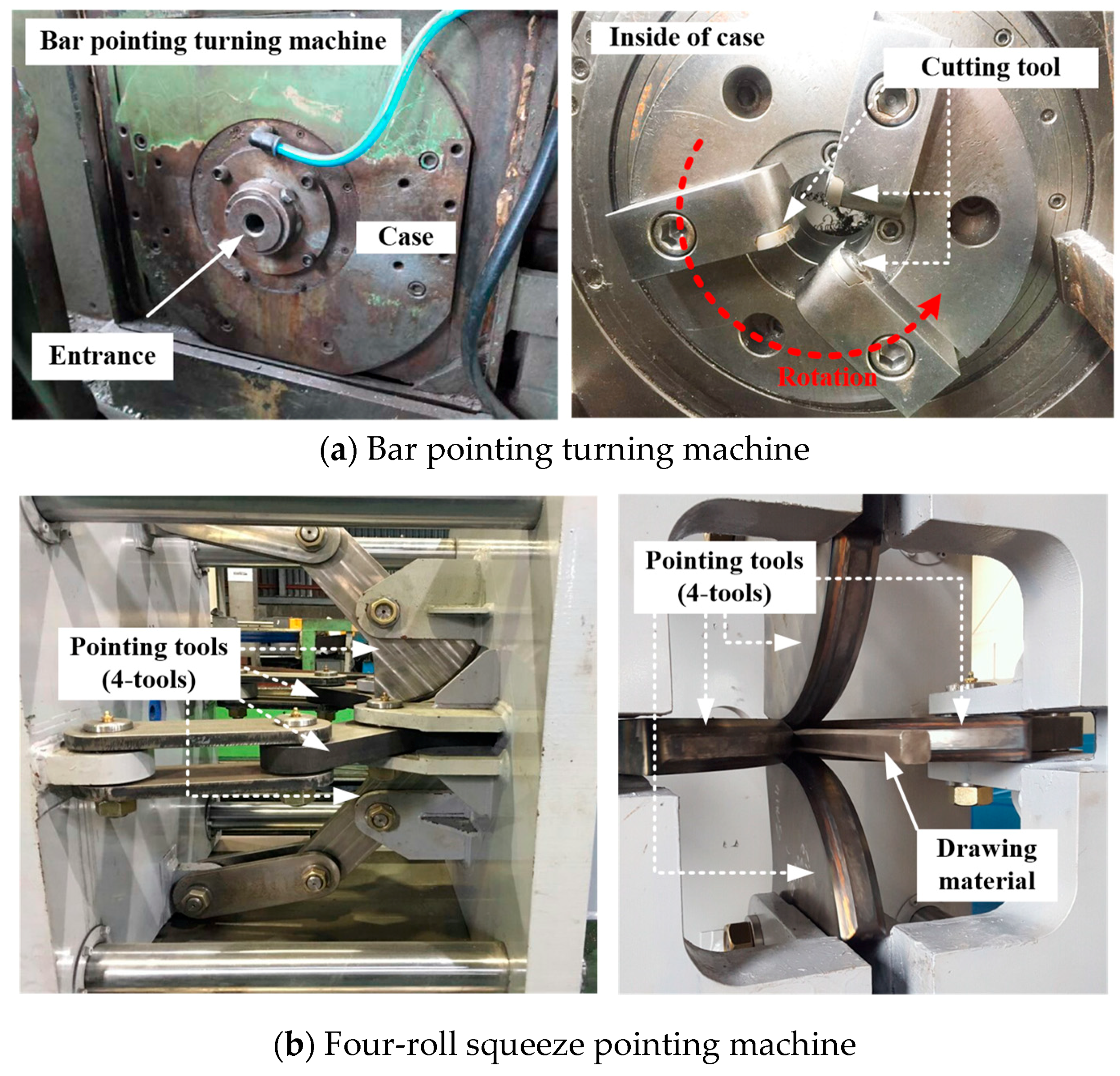
2.1. Four-Roll Squeeze Pointing Machine (RSPM)

A bar pointing turning machine, which is typically used, grinds the rod to form a circular shape. This machining process has low productivity, excessive material loss, and results in poor material properties; moreover, the drawing material breaks easily in the shape-drawing process. Therefore, a machine that ensures a higher material toughness is necessary.
In this study, a pointing machine for a multi-shape-drawing process was developed as shown in Figure 1a. Compared to the bar pointing turning machine, the RSPM is highly responsive to the complexity of the shape of the drawing material because both vertical and horizontal tools are used. Unlike conventional pointing machines, such as the bar pointing turning machine, the features of the pointing machine developed in this study include user-friendliness (automatic), cost-effective processing (using less material and time), and shaping and work-hardening to prevent the breaking of the drawing material in the shape-drawing process.
Once a drawing material is set in position, the material is transferred automatically by the feeding module. The pointing is operated by the motion of the hydraulic cylinder. The pointing process consists of three sequences, as shown in Figure 1b, and these are performed continuously. Firstly, the pointing tools starts to rotate counterclockwise on an axis of the tool by linear motion of the hydraulic cylinder (Sequence 1). Once the drawing material reaches a variable zone of the tool groove, an inclined plane of the drawing material is deformed with longitudinal elongation and shear deformation by the pointing tools (Sequence 2). Because the drawing material is deformed by the groove of the pointing tools, the groove should be designed to shape a variable zone. Finally, the straight zone of the drawing material is deformed (Sequence 3). Because this pointing process with three automatic sequences causes pre-strain of the material, the RSPM can work-harden the drawing material.

2.2. Tool Design for the RSPM

The cross-sectional shape of the drawing material is designed to minimize the reduction area of the pointing process and to increase the strength of the drawing material. For the circle-to-square drawing process, the drawing materials with cross-sectional shapes in Figure 2 are used for both the developed pointing machine and the bar pointing turning machine. Therefore, the cross-sectional shape of the tool groove of the pointing machine is similar to that of the pilger mill [13]. As shown in Figure 2, the section of the pointing tool can be divided into a straight zone (Zone I), a variable zone (Zone II), and a non-deforming zone (Zone III). In Zones I and III, the tool groove has a constant radius according to the longitudinal direction of the drawing material. Therefore, the angle of the tool groove at each section (θI or θIII) can be expressed as follows:
L s = ρ s θ I   or   I I I
where Ls is the arc length and ρs is the radius of the tool groove from the O-axis.
On the basis of the central axis of the drawing material and pointing tool, the inclined plane of the drawing material is expressed in Figure 3. To form the inclined plane of the drawing material, the angle of the tool groove in Zone II is expressed as the following relationships:
L s l / n = x i = ρ i tan β L s l , i = x i cos α = ρ j tan β cos α = ( ρ 1 y i ) tan β cos α L s l , i = ρ j θ I I
where Lsl is the total length of the inclined plane, Lsl,i is the divided length of the inclined plane with xi, ρi is the radius of the tool groove in the variable zone, and α is the angle of the inclined plane.
For this study, SCM440 was used as the tool material and the surface of the tool was subjected to a carburizing treatment to a minimum Rockwell C-scale hardness of HRC 45. In this study, the working angle of the pointing tools was 80°, which is the summed angle of Zones I, II, and III. The radius of the tool groove in Zone I, ρ1, was 210 mm.

2.3. Conditions of FE Simulation

To analyze the metal flow in the cross-section of the pointed area with the RSPM and drawn material, a finite element (FE) simulation of the pointing process was carried out as shown in Figure 4a. The workpiece for the FE simulation was a three-dimensional (3D) half model, and the mechanical properties of austenitic stainless steel 304 presented in Table 1 were applied. A friction coefficient (μ) of 0.12 was applied. The target shape of the drawing material and the metal flow in the cross-section were determined from the FE results. Therefore, the measuring points were determined as shown in Figure 4b.
Under the same conditions, such as reduction in area, material properties, and friction, the drawing load of the shape-drawing process is higher than that of the axisymmetric drawing process. Therefore, the pointing zone of the shape-drawing process can break easily.
For the circular shape pointed by the conventional turning machine, the fracture behavior of the pointing zone according to the initial billet size and the relationship with the half die angle and the pointing angle was analyzed. To investigate the fracture behavior according to the cross-sectional shape of the drawing material, FE simulations of the square bar drawing process were conducted using DEFORM-3D with a three-dimensional one-fourth FE model to reduce the computation time, which was enabled by the plane symmetrical configuration of the workpiece. The initial mesh structure of the one-fourth FE model was constructed with approximately 100,000 initial tetrahedral elements, and an automatic remeshing scheme was used for the numerical simulations. The dies were considered as rigid, and the workpieces were pulled in the drawing direction by using the sticking condition between the grip and the workpiece. The die shape and dimensions of the material for the FE simulations of square bar drawing are shown in Figure 5. The input parameters for the FE simulations of the square bar drawing process are the initial billet diameter, the half die angle, and the pointing angle. Table 2 lists the general conditions for the FE simulations. The variables are the diameter of the initial billet, the half die angle, and the pointing angle.
The Box–Behnken design and response surface method (RSM) was applied in the FE simulations. Three independent factors were considered as shown in Table 3. Furthermore, the results of the FE simulations using the Box–Behnken method were trained to learn the nonlinear relationship between the shape parameters using an artificial neural network (ANN) [14,15,16]. A total of 15 FE simulations were utilized to train and develop the ANN. Some interpolations of the FE results were performed on the intermediate input levels to enlarge the training data set.
To evaluate the effect of work-hardening of the RSPM, FE simulations of the pointing process and drawing process were carried out using DEFORM-3D with a three-dimensional one-fourth FE model. The initial mesh structure of the one-fourth FE model was constructed with approximately 100,000 initial tetrahedral elements, and an automatic remeshing scheme was used for the numerical simulations. The pointing tool for the FE simulation was modelled based on the design of the pointing tool mentioned in Section 2.2 as shown in Figure 4a. The input parameters for the FE simulations of the pointing process and the drawing process are listed in Table 4 and Table 2, respectively. The conditions of the pointing angle of 15° and those of the half die angle of 20°, for which fracture was predicted in Section 3.2, were applied. The initial circular material with a diameter of 26 mm was deformed to a square of 19.5 mm × 19.5 mm.

3. Experimental Results

3.1. Pointing Process and Drawing Process

In this study, two different pointing processes were carried out and the drawing materials were evaluated using a square bar drawing process. As shown in Figure 6, the bar pointing turning machine using cutting tools and the developed pointing machine using four pointing tools were used.
The pointing process using the bar pointing turning machine was performed to a pointing angle of 15° from the initial circular material of diameter 26 mm. Similarly, the pointing process using the RSPM was performed under the same conditions. However, the initial circular material was deformed to a square of 19.5 × 19.5 mm2. The drawing materials shown in Figure 7a were drawn through the drawing die with a half die angle of 20°.
The results of drawing processes show that the drawing material using the bar pointing turning machine was broken at an early stage of the drawing process. Necking and failure occurred. In contrast, the drawing material using the RSPM was intact as shown in Figure 7b. As shown in Figure 7c, a cup-and-cone fracture occurred near the boundary of the pointed zone and the drawn zone.

3.2. Hardness Measurements

The Vickers hardness (Hv) of the specimens of pointed and drawn material in Figure 8 was evaluated. The Vickers hardness of the drawing materials manufactured with each pointing machine was measured on polished glass samples using a Matsuzawa micro-hardness tester Model MXT-a with a pyramid-shaped diamond indenter and applying a load of 150 gf for 10 s. Measurements were taken at a minimum of 20 measuring points for each sample.
As shown in Figure 8, the hardness of the drawing material manufactured by the bar pointing turning machine was approximately 170 Hv. The hardness of the drawing material manufactured by the RSPM and the drawn material was similarly above approximately 350 Hv. The RSPM can work-harden the drawing material to the same extent as the drawing process. In the pointing process by the RSPM, the initial shape of the rod is deformed to square shape. Therefore, the points of 2, 4, and 8, at which the amount of deformation is greatest, has a slightly higher hardness than the others. However, it was shown that the surface hardness of the drawing material from the RSPM was slightly lower than that of the drawn specimen.

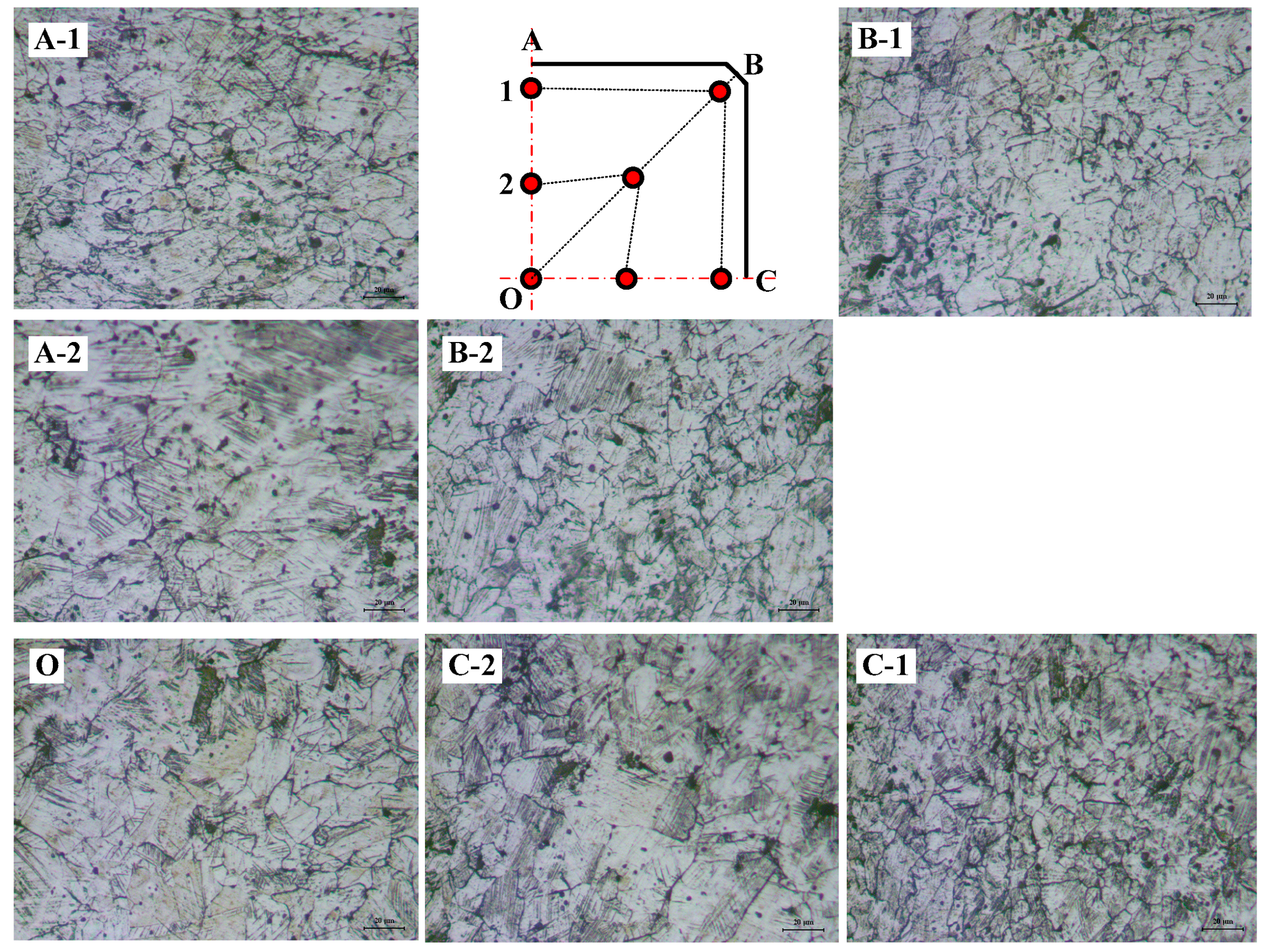
3.3. Microstructure of the Pointed Zone by the RSPM

Figure 9 shows the microstructure along the cross-section of the pointed area of RSPM. In an annealed soft state, the metastable austenitic stainless steels (MASSs) are fully austenitic (γ); they can be strengthened by grain refinement [17] and by its transformation into martensite (α’) under the application of stress/strain [18,19]. The increase of the work-hardening of the steel as a consequence of the martensitic transformation results in enhanced strength and formability, which makes MASSs good candidates for multi-stage processes [20,21,22].
The martensite phase is revealed in dark colors and the austenite is unetched. Parallel slip bands appeared in those grains that are favorably oriented with respect to the applied stress direction, where slip bands are localized crystallographic slip and, thus, cannot cross existing interfaces into other orientations [23]. It was indicated that the pointing process of the RSPM causes the strain-hardening, and the austenitic microstructure transforms to strain-induced α’-martensite phases during plastic deformation.

4. Discussion

4.1. Feasible Pointing Size for a Bar Pointing Turning Machine

Figure 10 and Figure 11 show the results of the ANN developed from the FE simulations to investigate the fracture behavior of the pointing zone. The numerical approaches for predicting the endurance limit regarding the fracture occurrence of the pointing zone using normalized Cockcroft–Latham’s ductile fracture criterion were carried out with the considered process parameters. The normalized Cockcroft–Latham’s criterion is represented in the following equation:
0 ε e f ( σ * / σ e f ) d ε e f = C
where σef is the effective stress, εeff is the effective strain in the fracture, and (σ*/σef) is a non-dimensional factor of the stress concentration, which represents the most tensile stress influence σ*. According to a generally accepted hypothesis, a plastic fracture occurs when the damage exceeds its critical value.
The uniaxial tensile test was simulated by FE analysis until the fracture strain, which is the result of a tensile test. Then, the critical damage value of STS 304 was derived through the FE simulation.
The relative angle was defined as a ratio of the half die angle and the pointing angle. For an initial billet diameter of 13 mm and a half die angle above 17.5°, it was indicated that the damage values of the pointing process become above a critical damage value of 0.803 as shown in Figure 10a. In the case of a high reduction in area and a high half die angle, the damage value of the pointed zone increases according to the relative angle between the half die angle and the pointing angle. In the case of a low reduction in area, the damage value is not only lower than the critical damage value, but the effect of the relative angle decreases as shown in Figure 10b. Therefore, the effect of the reduction in area is dominant. The damage values according to the reduction in area and the half die angle are valid to design the process and are indicated in Figure 11. The damage value increases above a 13.34% reduction in area. The damage value increases with increasing the half die angle and a reduction in area.

4.2. Comparison between Bar Pointing Turning Machine and RSPM

Figure 12 shows the shape of the drawing material and its damage value. The maximum damage value of the drawing material was approximately 0.426, which is below the critical damage value of 0.803. In addition, the fracture behavior of the drawing material deformed by the RSPM was evaluated using FE simulation of the drawing process with the drawing die shown in Figure 5.
Figure 13 shows the damage distribution of the pointed and drawn zones of the material as the results of the FE simulation of the square bar drawing process. The maximum damage value of plane A, which is the drawing material, is approximately 0.426 at the corner of the material. As shown in plane C in Figure 13, the square bar drawing process imposed a maximum damage value of approximately 0.429 on the corner of the material. The damage value of approximately 0.547 on plane B was the highest. Owing to the initial contact with both the drawing material and the drawing die, the damage value of plane B increases.
In the case of a circular shape of pointing, the drawing material was predicted to break under drawing conditions of a 20° half die angle and a 15° pointing angle. However, despite identical conditions, the drawing material from the RSPM was predicted to not break.

5. Conclusions

In this study, a new automatic pointing machine, RSPM, and its tool design method were proposed. RSPM is a pointing machine to improve the productivity of the pointing process as well as the shape-drawing process by preventing the breaking of the drawing material. The drawing materials manufactured by a bar pointing turning machine and the RSPM were compared. The following conclusions are obtained:
(1)
Under the same drawing condition, the material pointed by the RSPM was not broken, whereas that pointed by the bar pointing turning machine was. The experimental results of the pointing and drawing processes showed that the pointing process using the RSPM is useful to prevent the breaking of drawing material in the shape-drawing process.
(2)
The hardness of the drawing material from the RSPM and drawn material was similarly above approximately 350 Hv. The surface hardness of the drawing material from the RSPM is slightly lower than that of the drawn specimen. The hardness measurement results for each drawing material indicate that the RSPM can affect the extent of work-hardening as much as the shape-drawing process.
(3)
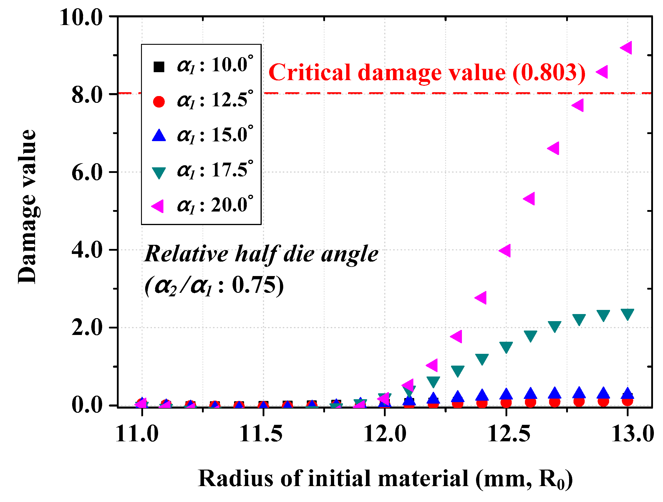
FE simulations for the shape-drawing process of drawing materials pointed by a bar pointing turning machine were conducted. For the circular shape pointed by the conventional turning machine, the fracture behavior of the drawing material according to the initial billet size and the relationship with the half die angle and the pointing angle was analyzed. As the reduction in area increases, the damage value increases to the critical damage value rapidly. The effect of the reduction in area was dominant.
(4)
For FE simulation of the pointing process and the shape-drawing process of drawing material pointed by RSPM, the damage value of the drawing material did not exceed the critical damage value despite the same drawing conditions.

Author Contributions

B.M.K. devised the main conceptual ideas and supervised the findings of this work; J.H.K. performed the experiments and analyzed the data. All authors discussed the result and contributed to the final manuscript.

Acknowledgments

This work was supported by a National Research Foundation of Korea (NRF) grant funded by the Korea government (MSIP) (No. 2017R1D1A1B03028012).

Conflicts of Interest

The authors declare no conflict of interest.

References

  1. Semiatin, S.L. ASM Handbook-Metalworking: Bulk Forming, 2nd ed.; ASM International: Novelty, OH, USA, 2008. [Google Scholar]
  2. Yoshida, K.; Yamada, S.; Hosaka, E. Precision Drawing of Deformed Stainless Steel Rail. In Proceedings of the Japanese Joint Conference for the Technology of Plasticity, Kyoto, Japan, 29–31 May 2009. [Google Scholar]
  3. Abitzur, B.; Narayan, C.; Chou, Y.T. Upper-bound solutions for flow through conical converging dies. Int. J. Mach. Tool Des. Res. 1982, 22, 197–214. [Google Scholar] [CrossRef]
  4. Boer, C.R.; Webster, W.D. Direct upper-bound solution and finite element approach to round-to-square drawing. J. Eng. Ind. 1985, 107, 254–260. [Google Scholar] [CrossRef]
  5. Lee, T.K.; Lee, C.J.; Lee, S.K.; Kim, B.M. Prediction of drawing load in the shape drawing process. Trans. Mater. Process. 2009, 18, 324–328. [Google Scholar]
  6. Basily, B.B.; Sansome, D.H. Some theoretical considerations for the direct drawing of section rod from round bar. Int. J. Mech. Sci. 1976, 18, 201–208. [Google Scholar] [CrossRef]
  7. Jokovic, Z.; Djapic, N. Method development for the calculation of the metal drawing passes schedule to which the hollomon curve applies. UPB Sci. Bull. Ser. B 2013, 75, 165–174. [Google Scholar]
  8. Lee, I.K.; Lee, S.K.; Lee, C.J.; Jeong, M.S.; Lee, J.W. A new method for predicting drawing load of shape drawing process. Int. J. Adv. Manuf. Technol. 2016, 84, 1747–1755. [Google Scholar] [CrossRef]
  9. Lee, S.K.; Lee, J.E.; Kim, B.M.; Kim, S.M. Die design in the complex shape drawing of cross roller guide to improve the dimensional accuracy. J. Mech. Sci. Technol. 2007, 21, 1573–1579. [Google Scholar] [CrossRef]
  10. Lee, S.K.; Lee, J.E.; Kim, S.M.; Kim, B.M. Design of intermediate die shape of multistage profile drawing for linear motion guide. J. Mech. Sci. Technol. 2010, 24, 2539–2544. [Google Scholar] [CrossRef]
  11. Lee, J.E.; Lee, T.K.; Lee, S.K.; Kim, B.M. Design of the cross sectional shape of intermediate die for shaped drawing of spline. Trans. Mater. Process. 2008, 17, 627–632. [Google Scholar]
  12. Mathan, G.; Manikandan, G.; Raj, A.; Rajgure, A.P. On the Reduction of High Starting Load in Cold Drawing of Circular Tubes. In Proceedings of the 5th International & 26th All India Manufacturing Technology, Design and Research Conference (AIMTDR 2014), Assam, India, 12–14 December 2014. [Google Scholar]
  13. Osika, J.; Palkowski, H.; Swiatkowski, K.; Pociecha, D.; Kula, A. Analysis of material deformation during the new cold tube rolling process realized on the new generation of pilger mills. Arch. Metall. Mater. 2009, 54, 1239–1251. [Google Scholar]
  14. Selvakumar, S.; Arulshri, K.P.; Padmanaban, K.P.; Sasikumar, K.S.K. Design and optimization of machining fixture layout using ANN and DOE. Int. J. Adv. Manuf. Technol. 2013, 65, 1573–1586. [Google Scholar] [CrossRef]
  15. Arnaiz-González, Á.; Fernández-Valdivielso, A.; Bustillo, A.; López de Lacalle, L.N. Using artificial neural networks for the prediction of dimensional error on inclined surfaces manufactured by ball-end milling. Int. J. Adv. Manuf. Technol. 2016, 83, 847–859. [Google Scholar] [CrossRef]
  16. Kim, J.H.; Lee, K.H.; Ko, D.C.; Lee, S.B.; Kim, B.M. Design of integrated safety vent in prismatic lithium-ion battery. J. Mech. Sci. Technol. 2017, 31, 2505–2511. [Google Scholar] [CrossRef]
  17. Celada-Casero, C.; Huang, B.M.; Aranda, M.M.; Yang, J.R.; San Martin, D. Mechanisms of ultrafine-grained austenite formation under different isochronal conditions in a cold-rolled metastable stainless steel. Mater. Charact. 2016, 118, 129–141. [Google Scholar] [CrossRef] [Green Version]
  18. Perdahcıŏ glu, E.S.; Geijselaers, H.J.M.; Groen, M. Influence of plastic strain on deformation-induced martensitic transformations. Scr. Mater. 2008, 58, 947–950. [Google Scholar] [CrossRef]
  19. Talonen, J.; Hänninen, H. Formation of shear bands and strain-induced martensite during plastic deformation of metastable austenitic stainless steels. Acta Mater. 2007, 55, 6108–6118. [Google Scholar] [CrossRef]
  20. Hedström, P.; Lindgren, L.E.; Almer, J.; Lienert, U.; Bernier, J.; Terner, M.; Odén, M. Load partitioning and strain-induced martensite formation during tensile loading of a metastable austenitic stainless steel. Metall. Mater. Trans. A 2009, 40, 1039–1048. [Google Scholar] [CrossRef]
  21. Spencer, K.; Embury, J.D.; Conlon, K.T.; Véron, M.; Bréchet, Y. Strengthening via the formation of strain-induced martensite in stainless steels. Mater. Sci. Eng. A 2004, 387–389, 873–881. [Google Scholar] [CrossRef]
  22. Post, J.; Nolles, H.; Datta, K.; Geijselaers, H.J.M. Experimental determination of the constitutive behaviour of a metastable austenitic stainless steel. Mater. Sci. Eng. A 2008, 498, 179–190. [Google Scholar] [CrossRef]
  23. Celada-Casero, C.; Kooiker, H.; Groen, M.; Post, J.; San-Martin, D. In-Situ Investigation of Strain-Induced Martensitic Transformation Kinetics in an Austenitic Stainless Steel by Inductive Measurements. Metals 2017, 7, 217. [Google Scholar] [CrossRef]
Figure 1. Schematic illustration of the four-roll squeeze pointing machine (RSPM) and its operating mechanism.
Metals 08 00427 g001aMetals 08 00427 g001b
Figure 2. Schematic illustration of the pointing tool.
Metals 08 00427 g002
Figure 3. Tool design for the pointing tool of the RSPM according to the drawing material.
Metals 08 00427 g003
Figure 4. (a) Finite element (FE) model for the pointing process of the RSPM; (b) Metal flow in the cross-section of the pointed zone and hardness measurement points.
Metals 08 00427 g004
Figure 5. Input parameters of the square bar drawing process for FE simulations.
Metals 08 00427 g005
Figure 6. Pointing machine setup for experiments.
Metals 08 00427 g006
Figure 7. (a) Results of the pointing process using the bar pointing turning machine and the RSPM; (b) Results of the drawing process; (c) Fracture surfaces of drawing material.
Metals 08 00427 g007
Figure 8. Distribution of the Vickers hardness of the drawing materials and the drawing material.
Metals 08 00427 g008
Figure 9. Microstructure of the drawing material pointed by the RSPM.
Metals 08 00427 g009
Figure 10. Damage values according to a relative angle and initial billet size for the square bar drawing process.
Metals 08 00427 g010
Figure 11. Feasible pointing size for the bar pointing turning process.
Metals 08 00427 g011
Figure 12. Result of the FE simulation for the pointing process using the RSPM.
Metals 08 00427 g012
Figure 13. Damage distribution of the pointed zone and the drawn zone of the material.
Metals 08 00427 g013
Table 1. Mechanical properties of the workpiece, Austenitic stainless steel 304.
PropertiesValues
Yield strength (MPa)311.55
Ultimate strength (MPa)628.16
Strain hardening coefficient, n0.4491
Strength coefficient, K (MPa)1308.58
Table 2. Input parameters required for the square bar drawing process.
Input ParametersValues
MaterialSTS304L
Initial billet diameter (mm)22~26
Critical damage value0.803
Die exit (mm2)20 × 20 (R1)
Half die angle (α1, °)10~20
Pointing zone diameter (mm)18
Pointing angle (α2, °)0.5 α1~1.0 α1
Friction coefficient (μ)0.057
Drawing velocity (mm/s2)3
Table 3. Box–Behnken design for FE simulations.
FactorsLevel 1Level 2Level 3
Initial billet diameter (2R0)222426
Half die angle (α1)101520
Pointing angle (α2)0.5 α10.75 α11.0 α1
Table 4. Input parameters required for the pointing process using RSPM.
Input ParametersValues
MaterialSTS304L
Initial billet diameter (mm)26
Critical damage value0.803
Pointing zone (mm2)19.5 × 19.5
Pointing angle (°)15
Friction coefficient (μ)0.12
Tool rotating speed (RPM)0.76

