Review

Current Progress in Solution Precursor Plasma Spraying of Cermets: A Review

by
Romnick Unabia
1,2,*,
Rolando Candidato, Jr.
1 and
Lech Pawłowski
2
1
Physics Department, College of Science and Mathematics, MSU-Iligan Institute of Technology, Iligan City 9200, Philippines
2
IRCER UMR 7315 CNRS, University of Limoges, Limoges Cedex 87068, France
*
Author to whom correspondence should be addressed.
Metals 2018, 8(6), 420; https://doi.org/10.3390/met8060420
Submission received: 1 May 2018 / Revised: 16 May 2018 / Accepted: 1 June 2018 / Published: 4 June 2018

Abstract

:
Ceramic and metal composites, known also as cermets, may considerably improve many material properties with regards to that of initial components. Hence, cermets are frequently applied in many technological fields. Among many processes which can be employed for cermet manufacturing, thermal spraying is one of the most frequently used. Conventional plasma spraying of powders is a popular and cost-effective manufacturing process. One of its most recent innovations, called solution precursor plasma spraying (SPPS), is an emerging coating deposition method which uses homogeneously mixed solution precursors as a feedstock. The technique enables a single-step deposition avoiding the powder preparation procedures. The nanostructured coatings developed by SPPS increasingly find a place in the field of surface engineering. The present review shows the recent progress in the fabrication of cermets using SPPS. The influence of starting solution precursors, such as their chemistry, concentration, and solvents used, to the micro-structural characteristics of cermet coatings is discussed. The effect of the operational plasma spray process parameters such as solution injection mode to the deposition process and coatings’ microstructure is also presented. Moreover, the advantages of the SPPS process and its drawbacks compared to the conventional powder plasma spraying process are discussed. Finally, some applications of SPPS cermet coatings are presented to understand the potential of the process.

1. Introduction

Recent studies demonstrate that deposition of coatings composed of metal phase embedded in ceramic matrix have considerably improved properties, such as hardness, wear resistance, surface reactivity, etc. [1,2,3,4,5,6,7,8,9,10]. The composite system of ceramics and metallic phases are known as cermets.
Atmospheric plasma spraying (APS) is a conventional thermal spray process which has been widely, and for many years, used for deposition of cermets used as protective coatings [1,3], thermal barrier coatings [4,5,6], and coatings in solid oxide fuel cells (SOFC) [7,8,9]. On the other hand, the production of coatings with fine microstructures (sub-micrometer/nanometer-scale) has been developed since the mid-1990s. These coatings improved its physical and mechanical properties, such as surface area, solubility, and many others [11,12,13,14,15,16,17,18,19,20]. One of the limitations of the APS process is the use of micrometer-sized (10–100 µm) powder feedstocks which makes it difficult to produce fine coating microstructures [17,18,19,20]. In addition, the resulting APS coatings have a characteristic lamellar structure due to successive impingement of splats, which reveals micro-defects such as unmelted particles, gas pores, and weak interconnection between splats that could deteriorate the coating’s functionality [4,5]. Therefore, the use of liquid feedstock in thermal spraying, such as the solution precursor plasma spraying process (SPPS), has been developed to overcome the limitations of the APS process [21,22].
SPPS offers a single-step deposition process of finely-structured cermet coatings by employing molecularly-mixed liquid precursors directly as the feedstock, which enables avoiding the powder and suspension preparation as shown in Figure 1 [10,13,14,17,18,19]. The use of solution precursors for thermal spraying was initiated by Karthikeyan et al. [21]. SPPS coating technology is industrially advantageous due to its ease in feedstock preparation.
Since the beginning of 21st century, there has been rapid development in nanostructured coating deposition using the SPPS process as reflected by a number of published articles [15,16,17,18,19,20,21,22]. However, most of the accounted papers focus on the deposition of ceramic materials alone and only a few have been reported on SPPS coating deposition for cermets (ceramic-metal composite) because of the oxidation potential of the metal-ions in the solution precursor [10,15]. The present review focuses on the current progress of solution precursor plasma spray for depositing cermet coatings used in various applications. In particular, the review gives an overview of the various factors affecting the final coating material, such as solution precursor preparations and physico-chemical interaction of the solution precursor with the high-temperature plasma jet.

2. Solution Precursor Plasma Spraying of Cermets

The properties of the starting solution precursors and operational plasma spray process parameters greatly influenced the physical and chemical characteristics of sprayed coatings. Thus, it is very important to screen those parameters which influence most of the properties of cermet coatings. Some of them are presented in Figure 2 together with the schematic representation of SPPS process. Selected parameters are discussed in the subsequent sections.

2.1. Solution Precursor Preparation

Solution precursors are generally prepared by mixing salts of metals such as nitrates and acetates in desired stoichiometry using various solvents (see Table 1). The chemistry of solution precursors, their concentration and solvent used, determine the characteristics of the resulting coatings [10,22,23,24,25,26,27,28,29]. The spraying process is accompanied by the decomposition of the precursor at the elevated temperature and high heat transfer of the plasma jet [10,22,23,24,25].
Lay et al., [26] reported the influence of the chemistry of the starting precursors on nickel-based SPPS cermet. They found that nickel-samaria doped ceria (Ni-SDC) has larger quantity of finer particles than nickel-yttria stabilized zirconia (Ni-YSZ) [26]. Moreover, Wang et al., [24] reported that the utilization of strontium-doped lanthanum manganite, (La0.8Sr0.2MnO3) as SOFC cathode material shows promising characteristics i.e., high electrochemical activity and thermal stability due to its high operating temperature (>800 °C) compared to Sm0.5Sr0.5CoO3 and La0.6Sr0.4Co0.2Fe0.8O3.
It was also reported that the good stoichiometric ratio of the ceramic-metallic species and/or the addition of complexing/chelating agent such as citric acid in the solution precursor can modify the chemistry of the solution [10,13,14,15]. Dom et al. [10] showed that the stoichiometric ratio of Zn to Fe being about 1:2 could thermodynamically favor the formation of desired cermet zinc ferrite composite phase rather than their corresponding metal-oxide phases such as zinc oxide, iron oxide, etc. [10]. Candidato et al. [13] also reported that as the zinc ion concentration into the hydroxyapatite (HA) ceramic matrix increases, formation of HA phases is hindered and favors the formation of calcium zinc phosphate impurity phase as shown in Figure 3. In addition, Sanpo et al. [15] presented that the utilization of citric acid as chelating agent with 20% concentration significantly favors the formation of more than 90% of cobalt ferrite phase due to chelate effect attributed to an increase in entropy resulting to a more stable composite material [15].
The concentration of the solution precursors is another aspect to be considered as it significantly influences the viscosity and surface tension of solution but has small effect on the pyrolysis and crystallization temperatures. High concentration solutions normally have higher viscosity and surface tension and need more injection pressure to be delivered to the core of the plasma jet. Solutions having low-concentration precursors generally experience surface precipitation leading to the formation of shells, while a highly-concentrated solution experiences volumetric precipitation leading to fully-melted splat microstructures. In order to induce volumetric precipitation, solution concentration must be near the equilibrium saturation concentration [17,27,28,29,30]. With these, high concentration solution precursors are used to deposit dense coatings. For example, Dom et al. [10] reported that a low concentration of zinc ferrite solutions yielded lower film thickness build-up per pass and certain impurity phases were observed, while high concentration yields a major fraction of zinc ferrite phases. However, beyond the equilibrium saturation concentration, the presence of unreacted solution precursor species was observed due to incomplete pyrolysis, thereby obtaining impurity phases in the coating.
The choice of solvent in the solution preparation is also important in the coating deposition as it relates to the ionic interactions at the molecular level due to macroscopic solvent properties, such as viscosity, surface tension, etc., and could modify the plasma jet’s thermodynamic and transport properties which directly affect the splat formation (see Table 2) [10,24,28,29,30].
Aqueous solution precursor feedstock is prone to produce larger droplet size due to its high surface tension affecting the droplet breakup. This phenomenon leads to the production of partially-pyrolyzed splats. A work by Wang et al. [24] on LSM cermet coatings reported porous sponge-like deposits and layered microstructure when the aqueous solution is used. These microstructures were attributed to the incomplete evaporation of solvent in-flight producing partially-pyrolyzed splats and in situ pyrolysis further occurs on the substrate [24]. This phenomenon is observable in aqueous solution due to the cooling effect of water, resulting in a ca. 25% decrease of the zone of high temperature in the plasma jet at over 8000 K [30].
On the contrary, when ethanol was employed as solvent, LSM cermets had a porous morphology with a large number of agglomerated small particles (0.2 to 2 µm) [29]. Unlike the aqueous solution, microstructures with mostly-crystallized perovskite phases were observed in LSM coatings when using ethanol as the solvent [29]. In another work, the production of zinc ferrite coatings using organic solvent exhibited an impurity phase (Fe2O3) unlike using aqueous solution, as shown in Figure 4 [10]. This can be attributed to easier evaporation of ethanol compared to water and to increase of plasma enthalpy and thermal conductivity, leading to a complete physical and chemical change of the precursor droplets, i.e., evaporation, precipitation, and densification inside the plasma jet region [24,28,29,30]. Chen et al. [28] investigated the phenomena related to the surface tension and evaporation. The authors reported that droplets having high surface tension and high boiling point solvent did not fully evaporate in the plasma while the solution droplets formed by the solvent having low surface tension and low boiling point could evaporate rapidly and could completely transform [28].
Lastly, appropriate solvents can be selected according to the application of the coatings, i.e., [27,28,29,30]:
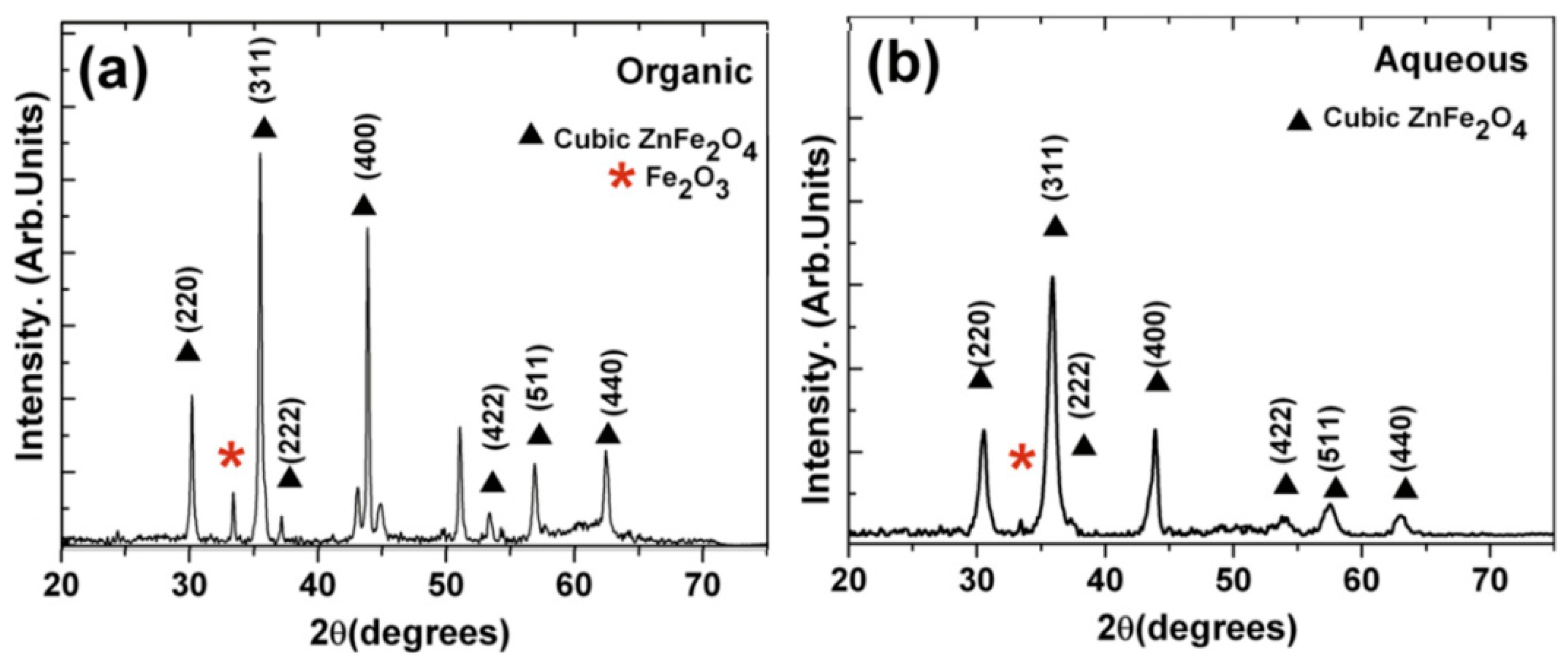
  • Aqueous solution precursor for the production of porous coatings (thermal barriers and biomedical ones);
  • Organic solvent resulting in fully-melted splats and a dense coating architecture for anti-wear applications.

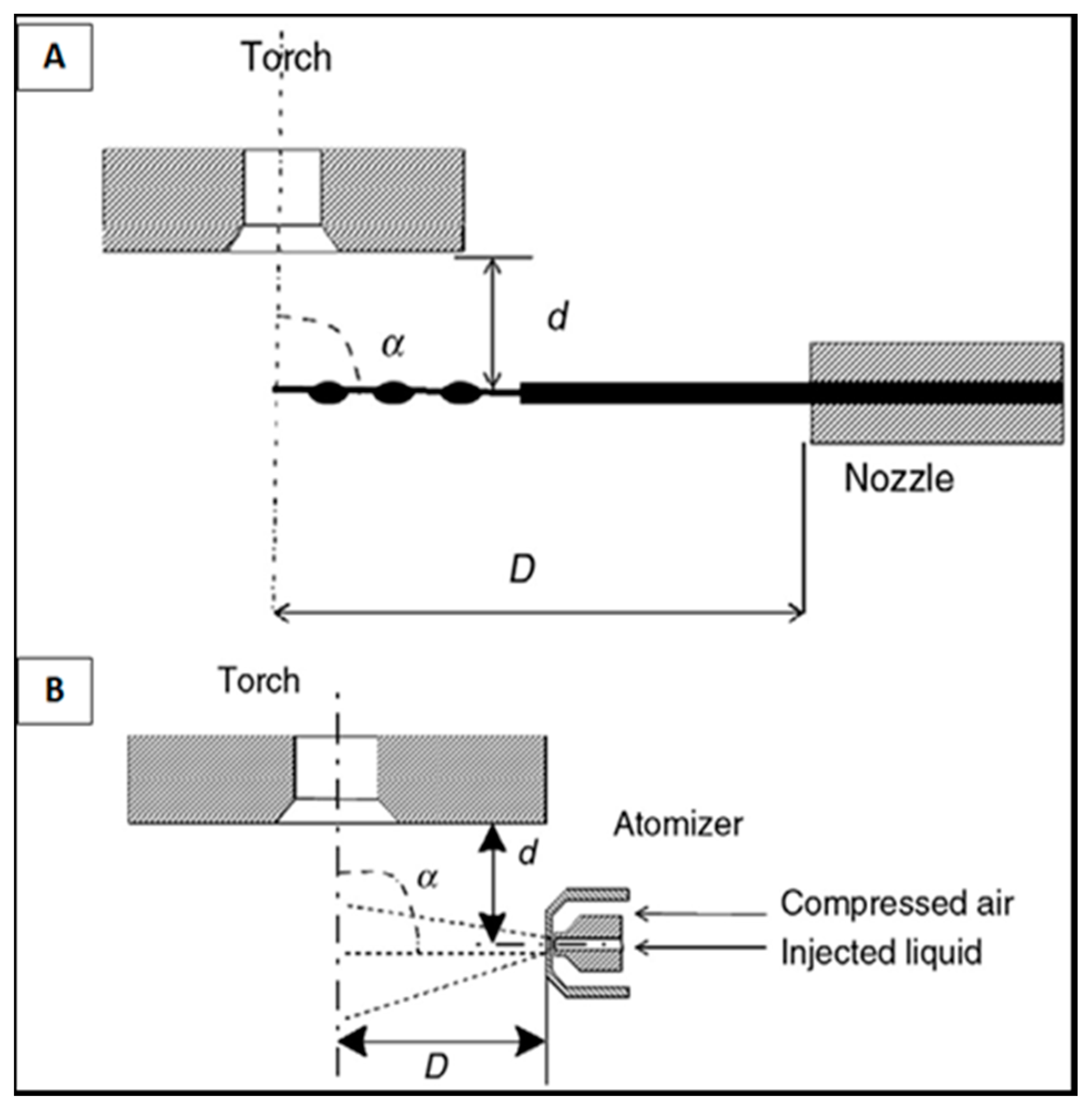
2.2. Injection of Solution Feedstock

The mechanism of solution injection into the plasma jet affects the heating of the droplets. The solution inside a pressurized container can be fed using a pneumatic system or in an open container using a peristaltic pump. The flow rate can be easily adjusted by varying the pressure or rotation of the roller, respectively. In general, clogging is not a problem in SPPS, unlike in the APS process. However, a flexible pipeline must be used and flushing the injector with ethanol or water is recommended to avoid gelling of the solution inside the injector. The types of injection that are frequently used in SPPS can be categorized depending on the type of injector used (mechanical or atomizing injector), the mode of injection (internal or external) and, on the choice between radial and axial injection setup [17,23,30,31]. The solution inside a pressurized container can be fed using a pneumatic system or in an open container using a peristaltic pump, as shown in Figure 5.
Mechanical injectors may use motor rollers to control the flow rate of the solution stream [22]. The formation of droplets from this stream is induced by an aerodynamic breakup through constant application of pressure, as shown in Figure 5A [17]. The resulting droplets using a mechanical injector are observed to have a relatively wide distribution of large droplets.
The large droplets may experience primary break-up before entering the plasma region. Upon penetrating at the plasma region, these large droplets undergo secondary break-up into smaller ones, as shown in Figure 6, influenced by the drag force acting on the droplet and its surface tension, which leads to the formation of finer microstructures [32]. With the high momentum of the large droplets, it can penetrate into the plasma core, enabling the droplet to be heated effectively. However, the good penetration of the stream of solution requires that the dynamic pressure of the solution is greater than the dynamic pressure of the plasma. This may be mathematically expressed as [17,22]:
ρυ2solution > ρυ2plasma,
Wang et al. [24], reported that mechanically-deposited strontium-doped lanthanum manganite (LSM) coatings present a partially crystallized perovskite phase with a fraction of the amorphous structure which could be attributed to the penetration and dwell time of the droplets in the plasma jet [24].
Figure 5B describes an atomizing injector which utilizes an atomizing gas to provide pressure on the solution precursor in order to break it up into small droplets. These atomized droplets, 2–100 microns in size, penetrate into the plasma jet core inducing an immediate thermal reaction of the solute due to fast evaporation of the solvent [17,33]. The direct contact of the atomized solution droplets into the hot plasma core result in the rapid formation of the LSM coatings, indicating a crystalline La0.5Sr0.5MnO3 perovskite phase. The XRD spectra of the LSM coatings shows broadened peaks because of the low peak-to-noise ratio of the deposits due to their small crystallite sizes associated with the breakup of the solution precursor into finer droplet sizes [24]. However, the size distribution of the droplets in this type of injector still depends in the nozzle geometry, the gas velocity and flow rate, and the property of the solvents used.
The solution precursor can be delivered into the plasma jet by axial or radial direction [33]. In axial injection, the droplet enters directly into the high-temperature plasma core where the solvent starts to evaporate rapidly, that results in the solute concentration near the droplet surface. This injection mode allows solute saturation in a short period of time. Due to the rapid heating process in axial injection the solution precursor droplet can undergo full pyrolization resulting in a dense coating formation [33]. Metcalfe et al., [31] studied the deposition of a Ni-YSZ cermet coating by axial injection with varying torch power. The authors reported a decrease of the nickel content in the composite coatings as the torch power decreased. This could result from the fast evaporation of nickel metal (boiling point at 2732.0 °C) [31].
With radial injection of the solution precursor the heating process is much slower compared to the axial one. The droplets interact first with the outer part of the plasma region, which is colder than the plasma core. This injection method is useful for large droplet sizes which may penetrate easier into the jet [17,18,33]. The study of Michaux [34] demonstrated the formation of Ni-based cermets with YSZ by SPPS using radial injection. It showed the homogeneous distribution of NiO in the YSZ matrix having a fine microstructure that could be induced by efficient internal circulation of the solvent in the droplets and by rapid diffusion of heat within the droplet.

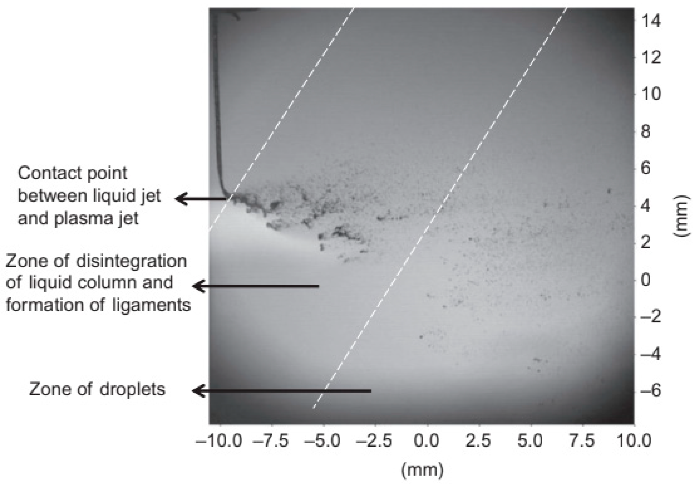
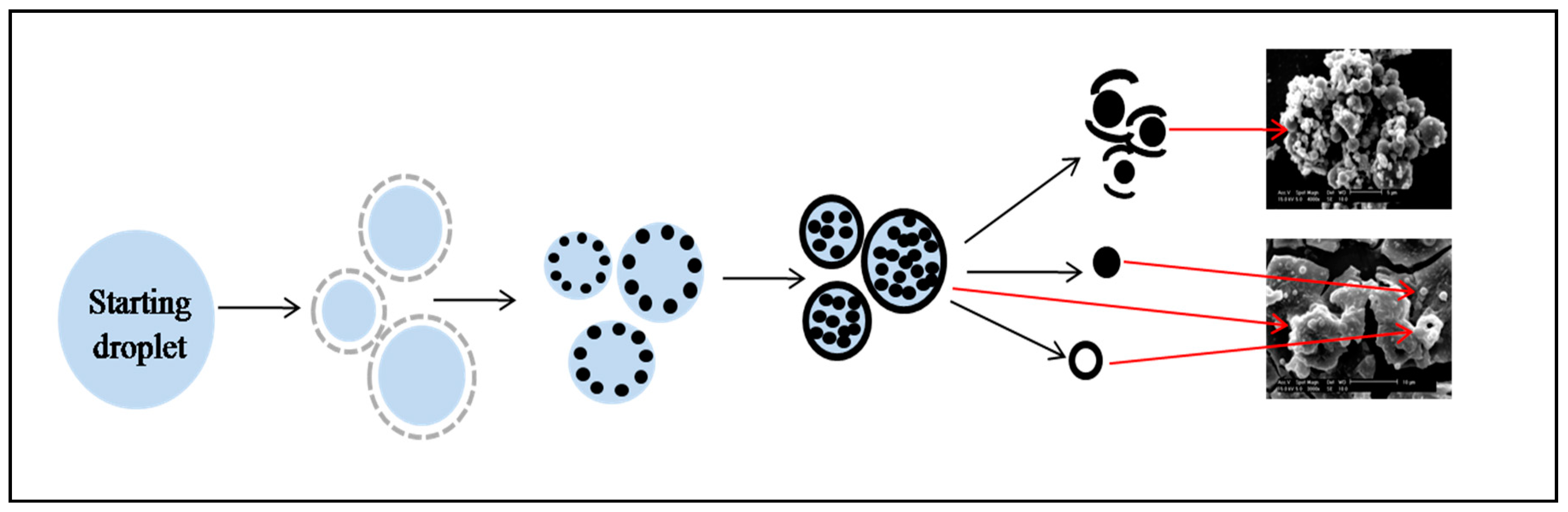
2.3. Phenomena in Flight

Different phenomena occur when the injected solution makes contact with the plasma jet, as discussed in many studies [17,22,35,36,37], are presented in this section in a chronological way. Initially, the liquid stream or large droplets break-up into small droplets due to the strong shear stress of the plasma flow [36]. After the break-up, the fragmented droplets experience rapid solvent evaporation and the increase of solute concentration follows. The precipitation inside of liquid droplets leads to the solid particle formation prior to coating deposition. The droplets may undergo volumetric or surface precipitation. Fine droplets tend to precipitate volumetrically, which is also known as homogeneous nucleation, which results in splat formation. On the other hand, larger droplets tend to precipitate superficially resulting in shell formation. If the solid shell is impermeable, internal pressurization takes place leading to the shell fracture. This may lead to the formation of cracked shells. The cracked shell may become molten and form spherical particles, as shown in Figure 7. The different particle morphologies formed by SPPS have been discussed in the work of Saha et al. [35]. Ozturk et al. [37] modeled the formation of the solid crust at precipitation occurring in a single droplet. The solid particles undergo heating and melting depending on their residence time inside the plasma jet. The evaporation from the molten solid may take place. The vapors may condense and form the nanoparticles.
Figure 8 is a high magnification micrograph of the surface of an SPPS Zn-HA coating showing the different particles formed in-flight deposited onto the substrate. The chemical phenomena of the solution occurring in-flight can be experimentally tested under equilibrium conditions with the use of thermogravimetric-differential thermal analyzer (DTA-TGA). In general, the chemical reactions start with the evaporation of solvent, pyrolysis of the precursor, and crystallization or oxidation of the precursor [27,28,38].
Michaux et al. [34] identified the sequence of chemical reaction in the fabrication of NiO/8YSZ cermet:
  • The exothermic reaction occurs first around 100 °C corresponding to ethanol solvent evaporation.
  • The endothermic peak at 300 °C corresponded to decomposition of nitrate precursors.
  • The endothermic peak at around 400 °C indicated the oxidation of precursors forming NiO doped with YSZ.

2.4. Cermet Coatings Formation

The microstructure of the sprayed cermet depends on the in-flight phenomena of the plasma jet discussed above. The particles arriving on the substrate or previously-deposited coating generally have sizes in the sub-micrometer or nanometer range [40,41]. To understand the coating formation, the deposits obtained from a single torch scan, as shown in Figure 9, can be studied [41].
Figure 9a shows deposited melted or partially melted spherical particles (~0.3 µm in diameter), which resulted from the evaporation of solvent at the surface of the small droplets [33,35,41]. The small sintered particles (~1 µm) are like the melted ones, but deposited before melting occurs, as shown in Figure 9b [33,35,37,41]. These small particles could have stuck together forming agglomerates as it reaches the substrate, as shown in Figure 9c. Such particles are the major deposit elements of the coating microstructure which contributes to the small pores in the coating [41]. The large pores in coatings due to the stacking of irregularly shaped agglomerates, such as dome-like ones, are shown in Figure 10 [39].
On the other hand, the wet agglomerates depicted in Figure 9d are some droplets entrained in the cold region of the plasma jet which experienced less heating and only partial pyrolization before impact. They may contribute in formation of a sponge-like structure, as reported by Wang et al. [24]. Figure 9e also shows the wet agglomerates formed with less amount of solvent. This type of deposit is formed through continuous evaporation of the solvent when vapors escaped by fine pores between small particles when impacting the substrate. Finally, the solution droplets that bounced away from the plasma core without experiencing effective heating are shown in Figure 9f. These wet droplets could have been generated by larger solution droplets which undergo in situ pyrolization after impacting the substrate’s surface [41].

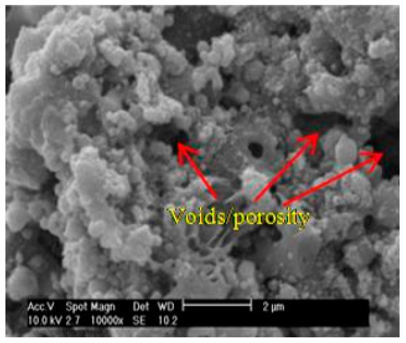
3. Microstructure of Cermet Coatings

Microstructure is an important factor determining the final properties of solution plasma sprayed coatings. The microstructure results from impact of the different particles on the substrate or previously deposited coating, namely: (i) melted particles; (ii) small sintered particles; (iii) dry agglomerates; (iv) wet agglomerates; and, (v) wet droplets, as described in many papers [17,22,40].
Unlike in conventional plasma spraying (APS), where large splats are formed, SPPS-prepared coatings exhibit many different microstructural features. The APS-deposited Ni-YSZ (see Figure 11) cermet coating cross-section shows a porous lamellar microstructure with voids and unmelted particles [42].
On the contrary, uniformly dense microstructures with fine-scale porosity characterize the SPPS-deposited Ni-YSZ cermet coatings as reported by Michaux et al. [34]. Wang and Coyle [23] also reported that Ni-YSZ cermet coatings containing spherical YSZ particles of about 0.5 µm in diameter were held together by a continuous Ni matrix. The strong bonding between particles due to the continuous Ni matrix could improve the mechanical properties of the coating. Consequently, there are no studies yet on the investigation of the mechanical properties of cermet coatings deposited using the SPPS process.
Candidato et al. [13], reported that microstructures of both HA and Zn-doped HA coatings deposited under similar conditions showed the presence of agglomerated fine spherical particles and melted particles at the surface, which are characteristics of SPPS coatings. However, the cross-section of the Zn-doped HA cermet coating seems to be denser compared to the un-doped HA (Figure 12).
Additionally, Nishida (2009) reported that the addition of nickel particles into samaria-doped ceria modifies the microstructure of coating from including only spherical particles into the one with nano-spheres with embedded nanoparticles to be used in SOFC applications [43]. A porous microstructure with porosity in the form of interconnected networks of voids was observed for cermet coatings produced from an aqueous solution precursor [29]. The void in the coating’s architecture is a result from the decomposition of the partially pyrolyzed precursor which is submitted to in situ evaporation of the remaining solvent [44]. Figure 13 displays the surface morphology of the LSM cermet coating deposited using (Figure 13a) water and (Figure 13b) ethanol as solvents. The aqueous SPPS coating shows a porous sponge-like morphology with agglomerated solid (~0.5 µm) particles. On the other hand, ethanol SPPS coating shows similar porous morphology and agglomerated solid particles, but with the refinement of particle size (~0.2 µm) which attributed the increase of the triple phase boundary length between the YSZ and LSM cathode, decreasing cathode polarization.
As discussed in the previous sections, the chemistry of the initial precursors influences the microstructure of the final cermet coatings, as depicted in Figure 14, showing the SEM images of nickel-based cermets (a) Ni-YSZ and (b) Ni-SDC. Nickel-samaria-doped ceria (Ni-SDC) coating displays a microstructure composed of very fine spherical particles having micrometer and nanometer sizes similar to nickel-yttria-stabilized zirconia. The morphology of nickel particles in SPPS was already reported to be very fine, which suggests that its combination with samaria-doped ceria (SDC) does not promote the growth acceleration of the particles [26].
Due to the complex in-flight phenomena and the unique particle morphologies formed during the process, some interesting coatings’ microstructures and architectures can be generated in SPPS depending on the set of parameters used [26,33,34,42,45,46,47]. Lay et al. [45] reported on the deposition of Ni-SDC using different spray parameters (SP), namely, SP1, which has higher velocity, energy, and solution precursor flow rate compared to SP2. The latter has a lower solution concentration. Ni-SDC using SP1 displays poorly-adhered finer particles with greater porosity compared to SP2 (see Figure 15). The surface morphology of Ni-SDC, obtained using SP1, shows no splat-shaped microstructural features which indicates that partial pyrolization of droplets takes place in the plasma jet due to low solution concentration and higher plasma energy than SP2 with high solution concentration. Thus, evaporation of most elements in the plasma, and subsequent nucleation at the surface of the substrate, is highly possible leading to the deposition of less-adhering coatings.
Moreover, the injection of solution precursor into the plasma jet may influence the microstructure of the cermet coatings. The droplets obtained using a mechanical injector had initially large droplets which could have undergone secondary break-up to form finer droplets as discussed in Section 2.2 [17,22,23,32]. Consequently, the resulting microstructure of coatings sprayed using mechanically-injected solution shows a porous, agglomerated, dome-like structure with resolidified particles at the surface [23]. The injection by atomization produces about 2–100 micron droplets, which may undergo rapid evaporation. Consequently, the complete pyrolysis of the solute particles may occur at the interaction with the plasma jet [17,33,34]. The injection by atomization leads to the formation of irregular tower-like agglomerates of very fine particles with smooth surface deposits, as reported elsewhere [34].
On the other hand, the long interaction time between the solution precursor droplets and the plasma jet during the trajectory induces the effects of sintering and of local re-melting. Michaux et al. [34] reported porous architectures with voids for external/radially delivered Ni-YSZ cermet due to stacking of partially-molten splats forming cavities [34]. On the other hand, dense uniform-layered coating with fine-scale porosity were observed for the solution precursor introduced within the torch convergence tube, which is attributed to the faster heating of the droplet leading to complete pyrolysis (see Figure 16) [31]. Therefore, the microstructure of the ceramic-metal composite coatings can be influenced by the way of injection depending on the foreseen application.

4. Applications of SPPS Cermet Coatings

SPPS cermet coatings have a wide variety of potential and emerging applications. However, plasma spraying of ceramic-metal composite solution precursor is still in its development stage, this review presents an overview of some of the SPPS cermet applications as protective and performance-enhancing coatings.

4.1. Solid Oxide Fuel Cells (SOFC)

Cermet coatings deposited using the SPPS process have primarily been used as electrodes in SOFC applications. Strontium-doped lanthanum manganite (LSM) as a cathode and nickel-Yttria stabilized zirconia (Ni-YSZ) as an anode are ones that have been extensively studied [23,24,25,26,29,31,34,41,42,43,45,46,47,48]. Wang et al. [24,29] investigated the polarization of LSM SOFC cathode material deposited using water and ethanol as solvent, respectively. The polarization of the cathode at 1000 °C gives the lowest specific surface resistance that reached 0.15 Ω·cm2 for an alcohol SPPS LSM cathode, which is half of the polarization of the aqueous SPPS LSM cathode, which is 0.3 Ω·cm2. This decrease in cathode polarization using ethanol is influenced by the increase of the triple phase boundary (TPB), i.e., associated with its catalytic property of the coating which is also related to the microstructure of the coating, as discussed in Section 3 [19,46,48].
Another study by Li et al. [25] reported a low polarization of SOFC cathode of 0.07 Ω·cm2 at 900 °C using strontium-doped samarium cobaltite perovskite sprayed using a stand-off of 130 mm. The long dwell time of droplets resulted in the complete reaction of the precursor and in fine microstructures of the perovskite phase. The Ni-YSZ composite anode studied by the SPPS process shows that the performance of this type of electrode is influenced by the spray parameters, such as the solution composition, plasma gas composition, and the stand-off distance [34]. Metcalfe et al., [31] reported one of the highest power densities of 0.45 W/cm2 at 0.7 V and an open circuit potential of 1.05 V at 750 °C thanks to the use of concentrated citric acid as an additive. Wang et al. [23] studied the electrical resistance of Ni-YSZ coatings at different temperatures which shows a decrease in the inverse of the electrical resistance with increasing temperature confirming the existence of continuous network of Ni in the coating [23].
The increase of spray distance and variation of plasma working gas mixtures modified the coatings microstructures [34]. Further works are still underway to better understand the electrochemical properties of SOFCs.

4.2. Catalyst

Cermet photocatalysts by SPPS were rarely investigated. Dom et al. [10] demonstrates SPPS deposition of porous films of pure spinel zinc-ferrite phases with a band gap of ~1.9 eV which favors the degradation of methylene blue pollutant under solar radiation. Figure 17 shows the substantial increase of photo-degradation efficiency η of SPPS zinc ferrite films with increasing film thickness from 25 µm to 50 µm. Although it is not comparable for the powder catalyst from solid state reaction routes, SPPS zinc ferrite films still demonstrate their potential in photocatalysis applications. Exploration of the SPPS process with appropriate controls on the critical spray parameters to produce new photocatalytic coatings has been taken into account in order to have niche applications.

4.3. Biomedical Coatings

Biomedical coatings have been utilized to promote bone growth at the surface of implants [13,15,39]. These coatings are deposited by an FDA-approved process, i.e., atmospheric plasma spraying [20]. Generally, the bioceramic coatings have limited use because of their low mechanical strength. Hence, by reinforcing the metal particles in the ceramic-based matrix forming the cermet coating enhances the strength, i.e., the fracture toughness and the wear resistance of the coatings for load-bearing applications [19,20]. Cermet coatings containing metal particles of zinc, silver, and copper do not only improve the mechanical strength of the coatings, but may promote antibacterial properties [13]. A study of Candidato et al. [13] has successfully produced zinc-doped hydroxyapatite coatings using the SPPS process. The microstructure of the coatings transforms from a highly porous coating to a dense one by adding zinc to the hydroxyapatite matrix (see Figure 12). It was also reported that increasing the zinc concentration on the cermet coatings inhibits the formation of the hydroxyapatite phase. The optimal Zn content for Zn-HA coatings is 5%.
Sanpo et al. [15] reported the SPPS deposition of cobalt ferrite coatings for biomedical applications [15]. In their study, the phase content and the cermet coating microstructure were greatly influenced by the chelating agent used. As-sprayed cobalt ferrite coating shows incomplete pyrolysis of the splats with a larger amount of other oxide phases. With the addition of citric acid as a chelating agent, the formation of 90% cobalt ferrite phase was achieved and fully-melted splats were observed. In fact, the chelating agents could have helped in the homogeneous interaction of mineral ions preventing the undesirable spontaneous condensation of cobalt and iron cations [14,15,16].
With these promising results, cermet coatings under the SPPS process are also a viable candidate for biomedical application. However, evaluation on the biological properties of the cermet coatings by SPPS is yet to be done.

Author Contributions

L.P. initiated this review article. R.C.J., R.U. and L.P. conceptualized the flow and contents of this review. R.U. gathered the necessary literatures for the article and wrote the body of the review paper. R.C.J. helped on the abstract and subsections of the paper. L.P. contributes on correcting the technical aspect of the review article.

Acknowledgments

Romnick Unabia would like to acknowledge the Department of Science and Technology- Accelerated Science and Technology Human Resource Development Program (DOST-ASTHRDP) for the scholarship grant, and Department of Science and Technology- Philippine Council for Industry, Energy and Emerging Technology Research and Development (DOST-PCIEERD) for the financial grant.

Conflicts of Interest

The authors declare no conflict of interest.

Symbol

ρDensity of the fluid
LvLatent heat of vaporization, J·kg−1
Ohm
ηPhoto-degradation efficiency, %
cpSpecific heat, J·kg−1·K−1
σsSurface tension, J/m2
TvVaporization temperature, K
υ2solutionVelocity of the solution
υ2plasmaVelocity of the plasma gas
µsViscosity, Pa·s

Abbreviations

APSAtmospheric plasma spray
CZPCalcium zinc phosphate
DTA-TGAThermogravimetric-differential thermal analyzer
FDAFood and Drugs Administration
HAHydroxyapatite
LSMStrontium-doped lanthanum manganite
Ni-SDCNickel samaria-doped ceria
Ni-YSZNickel Yttria stabilized zirconia
SOFCSolid oxide fuel cells
SPSpray parameters
SPPSSolution precursor plasma spray
SPSSuspension plasma spray
TCPTri-calcium phosphate
TPBTriple phase boundary
Zn-HAZinc-doped Hydroxyapatite

References

  1. Ageorges, H.; Ctibor, P.; Medarhri, Z.; Touimi, S.; Fauchais, P. Influence of the metallic matrix ratio on the wear resistance (dry and slurry abrasion) of plasma sprayed cermet (chromia/stainless steel) coatings. Surf. Coat. Technol. 2006, 201, 2006–2011. [Google Scholar] [CrossRef]
  2. Basak, A.K.; Achanta, S.; Celis, J.P.; Vardavoulias, M.; Matteazzi, P. Structure and mechanical properties of plasma sprayed nanostructured alumina and FeCuAl-alumina cermet coatings. Surf. Coat. Technol. 2008, 202, 2368–2373. [Google Scholar] [CrossRef]
  3. Xu, J.; Zou, B.; Zhao, S.; Hui, Y.; Huang, W.; Zhou, X.; Wang, Y.; Cai, X.; Cao, X. Fabrication and properties of ZrC-ZrB2/Ni cermet coatings on magnesium alloy by atmospheric plasma spraying of SHS powders. Ceram. Int. 2014, 40, 15537–15544. [Google Scholar] [CrossRef]
  4. Zhao, D.; Luo, F.; Zhou, W.; Zhu, D. Effect of critical plasma spray parameters on the complex permittivity and microstructure by plasma spraying Cr/Al2O3 coatings. Appl. Surf. Sci. 2013, 264, 545–551. [Google Scholar] [CrossRef]
  5. Deen, K.M.; Afsal, M.; Lui, Y.; Farooq, A.; Ahmad, A.; Asselin, E. Improved corrosion resistance of air plasma sprayed WC-12%Co cermet coating by laser re-melting process. Mater. Lett. 2017, 191, 34–37. [Google Scholar] [CrossRef]
  6. Zhu, H.B.; Li, H.; Li, Z.X. Plasma sprayed TiB2-Ni cermet coatings: Effect of feedstock characteristics on the microstructure and tribological performance. Surf. Coat. Technol. 2013, 235, 620–627. [Google Scholar] [CrossRef]
  7. Li, C.J.; Li, C.X.; Xing, Y.; Xie, Y.; Long, H. Influence of characteristics of stabilized zirconia electrolyte on performance of cermets supported tubular SOFCs. Rare Met. 2006, 25, 273–279. [Google Scholar] [CrossRef]
  8. Li, C.J.; Li, C.X.; Xing, Y.Z.; Gao, M.; Yang, G.J. Influence of YSZ electrolyte thickness on the characteristics of plasma-sprayed cermet supported tubular SOFC. Solid State Ion. 2006, 177, 2065–2069. [Google Scholar] [CrossRef]
  9. Li, C.X.; Li, C.J.; Guo, L.J. Effect of composition of NiO/YSZ anode on the polarization characteristics of SOFC fabricated by atmospheric plasma spraying. Int. J. Hydrog. Energy 2010, 35, 2964–2969. [Google Scholar] [CrossRef]
  10. Dom, R.; Sivakumar, G.; Hebalkar, N.Y.; Joshi, S.V.; Borse, P.H. Deposition of nanostructured photocatalytic zinc ferrite films using solution precursor plasma spraying. Mater. Res. Bull. 2012, 47, 562–570. [Google Scholar] [CrossRef]
  11. Watanabe, M.; Yamashita, H.; Chen, X.; Yamanaka, J.; Kotobuki, M.; Suzuki, H.; Uchida, H. Nano-sized Ni particles on hollow alumina ball: Catalysts for hydrogen production. Appl. Catal. B Environ. 2007, 71, 237–245. [Google Scholar] [CrossRef]
  12. Li, X.; Ma, W.; Wen, J.; Bai, Y.; Sun, L.; Chen, B.; Dong, H.; Shuang, Y. Preparation of SrZrO3 Thermal Barrier Coating by Solution Precursor Plasma Spray. J. Therm. Spray Technol. 2017, 26, 371–377. [Google Scholar] [CrossRef]
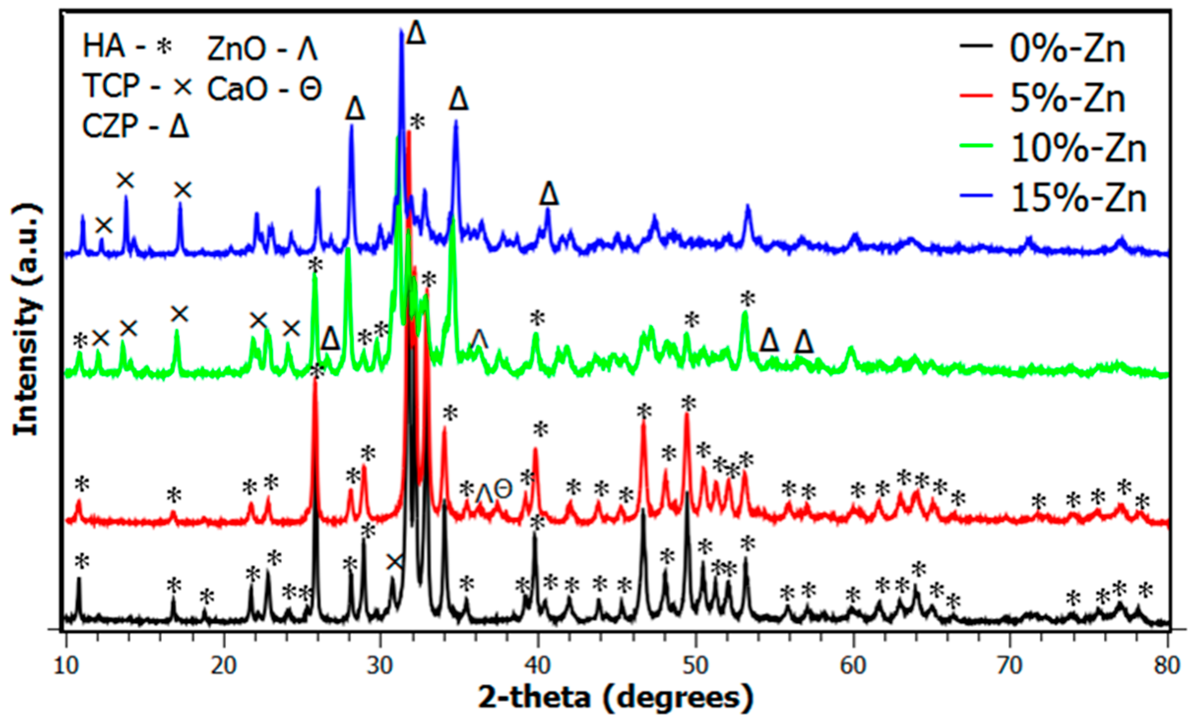
  13. Candidato, R.; Sergi, R.; Jouin, J.; Noguera, O.; Pawlowski, L. Advanced microstructural study of solution precursor plasma sprayed Zn doped hydroxyapatite coatings. J. Eur. Ceram. Soc. 2018, 38, 2134–2144. [Google Scholar] [CrossRef]
  14. Sanpo, N.; Ang, A.S.M.; Hasan, F.; Wang, J.; Berndt, C. Phase and Microstructures of solution precursor plasma sprayed cobalt ferrite splats. In Proceedings of the 5th Asian Thermal Spray Conference, Tsukuba, Japan, 26–28 November 2012; pp. 145–146. [Google Scholar]
  15. Sanpo, N.; Berndt, C.; Ang, A.S.M.; Wang, J. Effects of the chelating agent contents on the topography, composition, and phase of SPPS-deposited cobalt ferrite splats. Surf. Coat. Technol. 2013, 232, 247–253. [Google Scholar] [CrossRef]
  16. Sanpo, N.; Wang, J.; Ang, A.S.M.; Berndt, C. Influence of the different organic chelating agents on the topography, physical properties and phase of SPPS-deposited spinel ferrite splats. Appl. Surf. Sci. 2013, 284, 171–178. [Google Scholar] [CrossRef]
  17. Pawłowski, L. Suspension and Solution Thermal Spray coatings. Surf. Coat. Technol. 2009, 203, 2807–2829. [Google Scholar] [CrossRef]
  18. Killinger, A.; Gadow, R.; Mauer, G.; Guignard, A.; Vaben, R.; Stover, D. Review of new developments in suspension and solution precursor thermal spray processes. J. Therm. Spray Technol. 2011, 20, 677–695. [Google Scholar] [CrossRef]
  19. Brinley, E.; Babu, K.S.; Seal, S. The Solution Precursor Plasma Spray Processing of Nanomaterials. JOM 2007, 59, 54–59. [Google Scholar] [CrossRef]
  20. Keshri, A.K.; Agarwal, A. Plasma Processing of Nanomaterials for Functional Applications—A Review. Nanosci. Nanotechnol. Lett. 2012, 4, 228–250. [Google Scholar] [CrossRef]
  21. Karthikeyan, J.; Berndt, C.C.; Tikkanen, J.; Wang, J.Y.; King, A.H.; Herman, H. Preparation of nanophase materials by thermal spray processing of liquid precursors. NanoStruct. Mater. 1997, 9, 137–140. [Google Scholar] [CrossRef]
  22. Pawłowski, L. Application of solution precursor spray techniques to obtain ceramic films and coatings. Future Dev. Therm. Spray Coat. 2015, 123–141. [Google Scholar] [CrossRef]
  23. Wang, Y.; Coyle, T.W. Solution Precursor Plasma Spray of Nickel-Yttria Stabilized Zirconia anodes for solid fuel cell application. J. Therm. Spray Technol. 2007, 16, 898–904. [Google Scholar] [CrossRef]
  24. Wang, X.; Li, C.X.; Li, C.J.; Tian, L.; Yang, G. Microstructure and Electrochemical Behavior of La0.8Sr0.2MnO3 deposited by Solution Precursor Plasma Spraying. Rare Met. Mater. Eng. 2011, 40, 1881–1886. [Google Scholar] [CrossRef]
  25. Li, C.X.; Liu, S.; Zhang, Y.; Li, C.J. Characterization of the microstructure and electrochemical behavior of Sm0.7Sr0.3Co3-δ cathode deposited by solution precursor plasma spraying. Int. J. Hydrog. Energy 2012, 37, 13097–13102. [Google Scholar] [CrossRef]
  26. Lay, E.; Metcalfe, C.; Kesler, O. The influence of incorporating MgO into Ni-based cermets by plasma spraying on anode microstructural and chemical stability in dry methane. J. Power Sources 2012, 218, 237–243. [Google Scholar] [CrossRef]
  27. Chen, D.; Jordan, E.H.; Gell, M. Effect of solution concentration on splat formation and coating microstructure using the solution precursor plasma spray process. Surf. Coat. Technol. 2008, 202, 2132–2138. [Google Scholar] [CrossRef]
  28. Chen, D.; Jordan, E.H.; Gell, M. The Solution Precursor Plasma Spray Coatings: Influence of Solvent type. Plasma Chem. Plasma Process. 2010, 30, 111–119. [Google Scholar] [CrossRef]
  29. Wang, X.; Li, C.X.; Li, C.J.; Yang, G.J. Microstructure and polarization of La0.8Sr0.2MnO3 cathode deposited by alcohol solution precursor plasma spraying. Int. J. Hydrog. Energy 2012, 37, 12879–12885. [Google Scholar] [CrossRef]
  30. Fauchais, P.; Vardelle, A. Innovative and emerging processes in plasma spraying: From micro- to nano-structured coatings. J. Phys. D Appl. Phys. 2011, 44, 194011. [Google Scholar] [CrossRef]
  31. Metcalfe, C.; Grindler, E.L.; Kesler, O. Characterization of Ni-YSZ anodes for solid oxide fuel cells fabricated by solution precursor plasma spraying with axial feedstock injection. J. Power Sources 2014, 247, 831–839. [Google Scholar] [CrossRef]
  32. Marchland, C.; Mariaux, G.; Vardelle, M.; Vardelle, A. Injection and Aerodynamic Fragmentation of Liquid Precursors under Plasma Spray Conditions. In Proceedings of the 2nd International Workshop on Suspension and Solution Thermal Spraying, Tours, France, 5–7 June 2008. [Google Scholar]
  33. Ozturk, A.; Cetegen, B. Modeling of axially and transversely injected precursor droplets into a plasma environment. Int. J. Heat Mass Transf. 2005, 48, 4367–4383. [Google Scholar] [CrossRef]
  34. Michaux, P.; Montavon, G.; Grimaud, A.; Denoirjean, A.; Fauchais, P. Elaboration of Porous NiO/8YSZ Layers by several SPS and SPPS routes. J. Therm. Spray Technol. 2010, 19, 317–327. [Google Scholar] [CrossRef]
  35. Saha, A.; Seal, S.; Cetegen, B.; Jordan, E.; Ozturk, A.; Basu, S. Thermo-physical processes in cerium nitrate precursor droplets injected into high temperature plasma. Surf. Coat. Technol. 2009, 203, 2081–2091. [Google Scholar] [CrossRef]
  36. Sanpo, N. Solution Precursor Plasma Spray System; Springer: New York, NY, USA, 2014; Volume 7, ISBN 9783319070247. [Google Scholar]
  37. Ozturk, A.; Cetegen, B.M. Modelling of plasma assisted formation of precipitates in zirconium containing liquid precursor droplets. Mater. Sci. Eng. A 2004, 384, 331–351. [Google Scholar] [CrossRef]
  38. Xiong, H.; Weiqi, S. Investigation of Droplet Atomization and Evaporation in Solution Precursor Plasma Spray Coating. Coatings 2017, 7, 207. [Google Scholar] [CrossRef]
  39. Candidato, R.; Sokołowski, P.; Pawłowski, L.; Lecomte-Nana, G.; Constantinescu, C.; Denorjean, A. Development of hydroxyapatite coatings by solution precursor plasma spray process and their microstructural characterization. Surf. Coat. Technol. 2017, 318, 39–49. [Google Scholar] [CrossRef]
  40. Fauchais, P.; Vardelle, A. Solution and suspension plasma spraying of nanostructured coatings. Adv. Plasma Spray Appl. 2012, 149–188. [Google Scholar] [CrossRef]
  41. Shan, Y.G.; Wang, Y.L.; Coyle, T. Analysis of deposits formation in plasma spraying with liquid precursors. Appl. Therm. Eng. 2013, 51, 690–697. [Google Scholar] [CrossRef]
  42. Benyoucef, A.; Klein, D.; Coddet, C.; Benyoucef, B. Development and characterization of (Ni-Cu-Co)-YSZ and Cu-Co-YSZ cermets anode materials for SOFC application. Surf. Coat. Technol. 2008, 202, 2202–2207. [Google Scholar] [CrossRef]
  43. Nishida, R.; Kakinuma, K.; Nishino, H.; Kamino, T.; Yamashita, H.; Watanabe, M.; Uchida, H. Synthesis of nickel nanoparticles supported on hollow samaria-doped ceria particles via the solution-spray plasma technique: Anode catalysts for SOFCs. Solid State Ion. 2009, 180, 968–972. [Google Scholar] [CrossRef]
  44. Fauchais, P.; Rat, V.; Coudert, J.F.; Etchart-Salas, R.; Montavon, G. Operating parameters for suspension and solution plasma-spray coatings. Surf. Coat. Technol. 2008, 202, 4309–4317. [Google Scholar] [CrossRef]
  45. Lay, E.; Metcalfe, C.; Kesler, O. Influence of Tertiary Phases Incorporated into Ni-based Cermets by Solution Precursor Plasma Spraying (SPPS) on Anode Stability. ECS Trans. 2011, 35, 1303–1313. [Google Scholar] [CrossRef]
  46. Wang, Y.; Coyle, T.W. Solution Precursor Plasma Spray of Porous La0.8Sr0.2MnO3 Perovskite coatings for SOFC cathode application. J. Fuel Sci. Technol. 2011, 8, 021005. [Google Scholar] [CrossRef]
  47. Prakash, B.S.; Kumar, S.S.; Aruna, S.T. Microstructure and performance of LSM/YSZ based solid oxide fuel cell cathodes fabricated from solution combustion co-synthesized powders and by solution precursor plasma spraying. Surf. Coat. Technol. 2017, 310, 25–32. [Google Scholar] [CrossRef]
  48. Ma, X.; Dai, J.; Zhang, H.; Roth, J.; Xiao, T.D.; Reisner, D.E. Solid oxide fuel cell development by using novel plasma spray techniques. J. Fuel Cell Sci. Technol. 2005, 2, 190–196. [Google Scholar] [CrossRef]
Figure 1. Feedstocks used for thermal spraying processes which enable to obtain nano-structured coatings: (A) the pre-processed nano-powder particle used for the APS process; (B) the suspension droplet used for the SPS process; and (C) the homogeneously-mixed solution droplet used for SPPS process.
Metals 08 00420 g001
Figure 2. Schematic diagram of the solution precursor plasma spraying process showing the many different and important operational spray parameters that could influence the physical and chemical characteristics of cermet coatings.
Metals 08 00420 g002
Figure 3. X-ray diffraction diagram of the Zn-doped HA cermet coatings showing the evolution of the calcium zinc phosphate phase as zinc ion concentration increases. Reproduced with permission from [13], Elsevier, 2018.
Metals 08 00420 g003
Figure 4. X-ray diffraction spectra of deposited zinc ferrite films using (a) ethylene glycol, and (b) water as precursor solvents. Reproduced with permission from [10], Elsevier, 2012.
Metals 08 00420 g004
Figure 5. Schematic representation of the (A) mechanical injection and (B) spray atomization under external injection mode. Reproduced with permission from [17], Elsevier, 2009.
Metals 08 00420 g005
Figure 6. Aerodynamic interactions between the liquid stream and the high-temperature jet. Reproduced with permission from [32].
Metals 08 00420 g006
Figure 7. Possible route of particle formation in the SPPS process. Reproduced with permission from [39], Elsevier, 2017.
Metals 08 00420 g007
Figure 8. Surface micrograph of Zn-HA coating showing the different particle morphologies present like fine spheres, fragmented shells, and agglomerates. Reproduced with permission from [13], Elsevier, 2018.
Metals 08 00420 g008
Figure 9. Typical LSM deposits collected on the substrate at the distance 60 mm (a,b) and 70 mm (cf) from the plasma torch exit in the single scan experiments. Reproduced with permission from [41], Elsevier, 2013.
Metals 08 00420 g009aMetals 08 00420 g009b
Figure 10. SEM images at the (a) surface and (b) cross-section of HA coating from low concentration solution showing a dome-like microstructure. Reproduced with permission from [39], Elsevier, 2017.
Metals 08 00420 g010
Figure 11. SEM cross-sectional microstructure of Ni-YSZ by APS. Reproduced with permission from [42], Elsevier, 2008.
Metals 08 00420 g011
Figure 12. SEM images at the (left) surface and (right) cross-section of the coatings of (0%-Zn) un-doped HA and (5%-Zn) Zn-doped HA. Reproduced with permission from [13], Elsevier, 2018.
Metals 08 00420 g012
Figure 13. Surface morphology of an LSM cermet cathode deposited by (a) aqueous solution (reproduced with permission from [24], Elsevier, 2011) and (b) ethanol (reproduced with permission from [29], Elsevier, 2012) SPPS.
Metals 08 00420 g013
Figure 14. Scanning electron micrographs of (a) Ni-YSZ and (b) Ni-SDC SPPS cermet coatings. Reproduced with permission from [26], Elsevier, 2012.
Metals 08 00420 g014
Figure 15. Surface morphologies of Ni-SDC cermet coatings using (a) SP1 and (b) SP2. Reproduced with permission from [45], ELECTROCHEMICAL SOCIETY, 2011.
Metals 08 00420 g015
Figure 16. Cross-section of the Ni-YSZ anodes deposited via internal and axial injectors. Reproduced with permission from [31], Elsevier, 2014.
Metals 08 00420 g016
Figure 17. Methylene blue photo de-coloration efficiency versus ZnFe2O4 film thickness for films deposited at precursor pH = 8. The dotted horizontal line represents the efficiency of powder ZnFe2O4 photocatalyst synthesized by a solid state reaction. Reproduced with permission from [10], Elsevier, 2012.
Metals 08 00420 g017
Table 1. Solution precursor preparation for cermet coating fabrication via SPPS.
Final CoatingCoating ApplicationPrecursorSolvent UsedAdditiveReference
Zinc ferrite, ZnFe2O4PhotocatalysisZinc nitrate [Zn(NO3)2·6H2O] and ferric nitrate [Fe(NO3)3·9H2O]; ratio [Zn/Fe = 1/2]De-ionized water
Ethylene glycol
350 mM citric acidDom, R. et al. [10]
SrZrO3Thermal barrierZirconium acetate [Zr(C2H4O2)4] and strontium nitrate tetrahydrate [Sr(NO3)2·4H2O]; concentration = 1.6 mol/LDe-ionized water-Li, X. et al. [12]
Zinc-hydroxyapatite, Zn-HABiomedicalZinc nitrate hexahydrate [Zn(NO3)2·6H2O], calcium nitrate tetrahydrate [Ca(NO3)2·4H2O], and tri-ethyl phosphite [P(OEt)3]; ratio [(Ca + Zn)/P = 1.67]De-ionized water-Candidato, R. et al. [13]
Cobalt ferrite, CoFe2O4Biomedical, biomagnetic, and AntibacterialCobalt nitrate [Co.(NO3)2·6H2O] and ferric nitrate [Fe(NO3)3·9H2O]; ratio [Co./Fe = 1/2]De-ionized waterCitric acid as chelating agentSanpo et al. [14];
and Sanpo et al. [15]
Nickel- Yttria stabilized zirconia, Ni-YSZSolid oxide fuel cell (SOFC)ZrOCl2·6H2O, Y(NO3)3·6H2O and Ni(NO3)3·6H2O; concentration 60 vol. % of 8%YSZ and 40 vol. % of NiDistilled water-Wang, Y, and Coyle, T.W. [23]
Strontium doped lanthanum manganite, La0.8Sr0.2MnO3, LSMSolid oxide fuel cell (SOFC)La(NO3)3·6H2O, Sr(NO3)2 and Mn(NO3)2; molar ratio La:Sr:Mn = 0.8:0.2:1; total concentration 0.1 mol/LDistilled water
Ethanol
-Wang, X. et al. [24]
Wang, X. et al. [29]
Strontium doped samarium cobaltite, Sm0.7Sr0.3Co3-δSolid oxide fuel cell (SOFC)Sm(NO3)3·6H2O, Sr(NO3)2 and Co.(NO3)3·6H2O; molar ratio Sm:Sr:Co. = 0.7:0.3:1; total concentration 0.1 mol/LEthanol and distilled water-Li, C.X. et al. [25]
Table 2. Properties of two solvents commonly used in the SPPS process.
SolventSurface Tension σs (J·m−2) (Room Temp.)Viscosity µs (Pa·s) (Room Temp.)Specific Heat cp (J·kg−1·K−1) (at Room Temp.)Latent Heat of Evaporation Lv (J·kg−1)Evaporation Temperature Tv (K)
Water72 × 10−310−34.18 × 1032.26 × 106373
Ethanol22 × 10−31.06 × 10−32.44 × 1030.84 × 106351

