Article

Damage in Creep Aging Process of an Al-Zn-Mg-Cu Alloy: Experiments and Modeling

State Key Laboratory of Solidification Processing, School of Materials Science and Engineering, Northwestern Polytechnical University, Xi’an 710072, China
*
Author to whom correspondence should be addressed.
Metals 2018, 8(4), 285; https://doi.org/10.3390/met8040285
Submission received: 13 March 2018 / Revised: 10 April 2018 / Accepted: 16 April 2018 / Published: 20 April 2018

Abstract

:
In creep age forming (CAF), large integral panel components of high-strength aluminum alloy can be shaped and strengthened under external elastic loading at an elevated temperature through creep deformation and age hardening, simultaneously. However, the high ribbed structure on panel may induce stress concentration, inhomogeneous plastic deformation and even damage evolution on the bending rib, leading to the difficulty in controlling forming precision and material properties. Therefore, the generation and evolution of damage are necessary to be considered in the design of CAF. Taking 7050 aluminum alloy as the case material, the continuous and interrupted creep aging tests at 165 °C and three stress levels (300, 325, and 350 MPa) were conducted, and the corresponding material properties, precipitate, and damage microstructures were studied by mechanical properties tests, transmission electron microscope (TEM) and scanning electron microscope (SEM) characterizations. With the increase of stress level, the creep deformation occurs easier, the precipitates grow up faster, the creep damage occurs earlier, the growth rate and the size of microvoids increase, the mechanical properties decrease more rapidly, and the dominant mechanism of creep fracture changes from shear to microvoid coalescence. To simulate creep aging behavior with damage, a continuum damage mechanics (CDM) based model is calibrated and numerically implemented into ABAQUS solver via CREEP subroutine. The CAF of 7050 aluminum alloy panels with different height ribs were conducted by experiment and FE simulation. The forming process presents a typical stress relaxation phenomenon. The creep damage mainly occurs on the bending rib due to the severe stress concentration. With the increase of rib height, the creep strain and damage degree increase, but the springback decreases.

1. Introduction

Aim at the integrated manufacturing of shape forming and performance tailoring, creep age forming (CAF), as a novel and promising sheet metal forming technology, has been developed and applied to manufacturing the integral panel components in the aerospace field [1]. In general, the high strength aluminum alloy panel is elastic loaded to fit the die for obtaining the target shape under the artificial aging temperature. Under this specific thermal-mechanical field of CAF, the elastic deformation is gradually changed into permanent deformation by creep, and in the meantime, the material can be strengthened by aging [2]. The greatest advantage of CAF technology lies in the synchronous process of shape forming and material strengthening, then the traditional separate forming and heat treatment processes can be combined [3,4,5]. However, due to the complex structure of the integral panels, such as high rib, non-uniform thickness, and variable curvature, an uneven complex stress distribution will be produced on the panels in CAF. Especially, when the ribbed panel fits the die closely, the severe stress concentration can even produce local inhomogeneous plastic deformation on the bending rib. In this condition, irreversible creep damage is usually brought out with the increase of the creep deformation degree [6]. The production of damage will inevitably bring difficulties to the control of forming accuracy and product performance.
In recent years, many experimental and numerical studies about CAF mainly focused on the optimization of thermal-mechanical parameters, the selection of material initial tempers, the characterization of microstructures and properties, and the prediction of springback and performance. Arabi Jeshvaghani et al. [7,8] studied the effects of time and temperature on the springback and mechanical properties of 7075 aluminum alloy in CAF, and discussed the dominant mechanisms of age hardening and creep deformation. Lei et al. [9,10,11] investigated the effects of material initial tempers and the thermal-mechanical loading sequences on creep aging behaviors, and revealed that the 7050 aluminum alloy with re-solution temper creep aged under the sequence of loading prior to heating will obtain the desired creep deformation and material properties. Chen et al. [12,13,14] tested the microstructures, mechanical properties, and corrosion resistances of age-formed 7050 aluminum alloy, and found that, when compared with the stress-free aging, the precipitate coarsening and the grain boundary precipitation free zone widening, respectively, lead to the decrease of mechanical properties and the improvement of corrosion resistance in the creep aging condition. Ho et al. [15,16] established a set of physically-based unified creep constitutive equations to model aging hardening and creep deformation behaviors of 7010 aluminum alloy sheet in CAF, and obtained agreement well between the predicted and experimental results of yield strength and springback. These studies provide beneficial knowledge for the revelation of deformation mechanism, the optimization of technological parameters and the simulation of forming process. However, the experiments in the above studies were carried out by using the creep tensile tests under creep aging conditions and the simple CAF tests of flat panels. The complex structures of the ribbed panel and the induced stress concentration problems have not been involved.
Lam et al. [17] studied the effect of different rib stiffener designs on the springback of 2219 aluminum alloy ribbed panel in CAF, and found that the highest elastic stress is more likely to occur within and around the bending rib, taking up a greater proportion of the creep strain. Yang et al. [18] investigated the CAF of pre-deformed 2219 aluminum alloy ribbed panel by experiment and modeling, and pointed out that the final shape of the panel that was contributed from plastic deformation and creep deformation concurrently, with corresponding percentages of 33% and 67%, respectively. Although above studies have been carried out on the effects of the complex structures of ribbed panels, there are less reports aimed at the creep damage that is caused by stress concentration and inhomogeneous deformation. To simulate the creep deformation and aging hardening behaviors in CAF, a lot of constitutive models have been developed [1], however, the existing creep aging models did not involve the creep damage. Kowalewski et al. [19] proposed a creep constitutive model based on continuous damage mechanism (CDM), which contains two damage state variables to model the process of softening. However, the ability of the CDM based model to simulate damage in CAF is still to be studied.
In this work, taking an Al-Zn-Mg-Cu alloy AA7050 as the case material, the experimental studies on the creep aging behavior with damage were carried out using uniaxial tensile creep aging tests, mechanical property tests, precipitate and microvoid microstructures characterizations, and fracture morphology analyses. A CDM based creep aging model was calibrated and embedded into the commercial FE solver ABAQUS by CREEP subroutine to numerically investigate the CAF process of AA7050 ribbed panel, and the real CAF tests were carried out to verify the accuracy of the model.

2. Experimental Procedures

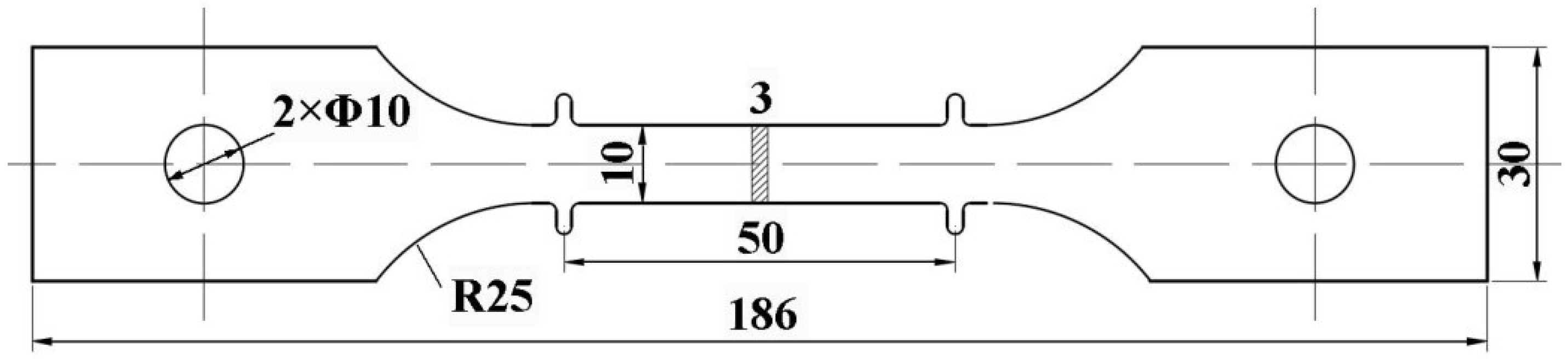
2.1. As-Received Material and Specimen Preparation

A 12.7 mm thick commercial 7050-T7451 (AMS 4050) aluminum alloy hot rolled plate that was provided by CORUS Aluminum was used in this work. The chemical composition is listed in Table 1. The creep aging test specimens were machined out from the hot rolled plate by wire electrical discharge machining (EDM), along the rolling direction. Figure 1 shows the geometry and the dimensions of the specimens. In order to regain the supersaturated solid solution state of alloy, the specimens were subjected to solution treatment at 470 °C for 50 min and subsequent water quenching. Before creep aging, all of the specimens were room temperature exposed for more than 24 h to obtain stable natural aging temper [20].

2.2. Creep Aging Tensile Tests

The creep aging tests were conducted under 300, 325 and 350 MPa until the specimens fractured. The testing apparatus is a specialized 100 kN electronic creep testing machine with a thermal environment furnace, which can control the testing temperature fluctuation less than 1 °C. The specimen was fitted in the middle of the furnace, and then the testing temperature was heated to 165 °C and detected around the top, middle, and bottom of specimen. After heating to the target temperature, the tensile stress was applied on the specimen under the loading speed of 0.5 mm/min, and then the stress was kept constant during subsequent creep aging process. The elongation of the specimen was measured by a probe-type grating line displacement transducer with the accuracy of 5 × 10⁻⁴ mm. To study the evolutions of creep damage, precipitate microstructure, and mechanical property during the above creep aging tests, a series of interrupted tests were performed under the same testing conditions. For each experimental condition, the total number of creep aging tensile tests was not limited until obtaining four sets of highly repetitive creep data to ensure the test credibility. One of the four sets of creep data was selected to analyze creep deformation, and the four creep aged specimens were used for the subsequent mechanical properties tests and microstructure characterization. In detail, three creep aged specimens were used in tensile tests to obtain the average values of yield strength (YS), tensile strength (TS), and elongation. The gauge section on the fourth one was divided into three parts by wire EDM, and then they were used for hardness test, precipitate characterization, and microvoid observation, respectively.

2.3. Mechanical Properties Tests and Microstructure Characterization

For the creep aged specimen, the room temperature tensile tests were carried out by a MTS CMT5205 universal material testing machine under a tensile speed of 2 mm/min, and the deformation of specimen was measured by the same extension meter as in the creep aging tensile test. Using a THV-1MD digital micro-Vickers hardness tester, the micro-hardness of each creep aged specimen was measured ten times in order to calculate an average hardness value.
The precipitate microstructures of creep aged specimens were characterized by a TECNAI G2 F30 transmission electron microscope (TEM) at 200 kV. In the preparation process of TEM specimens, a slice was cut away from the selected creep aged specimen by wire EDM and then frictional thinned to 60 μm thickness. Some 3 mm diameter disks were blanked out from the slice and twin-jet electro-polished in a solution of 20% perchloric acid and 80% ethanol (in volume) at −20 °C and 20 V. The morphologies of fractures and microvoids were observed by a JEOL JCM-6000 scanning electron microscope (SEM).

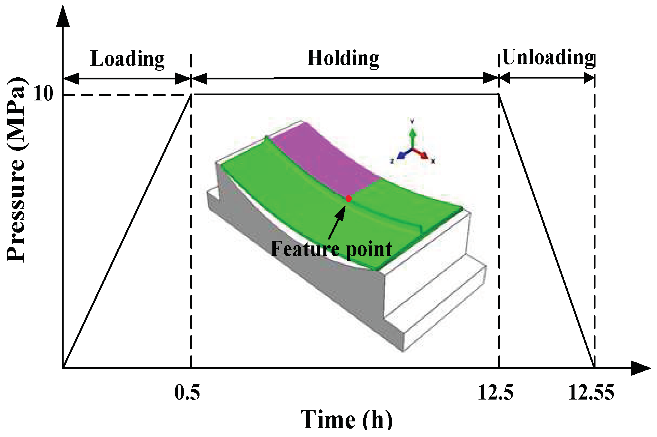
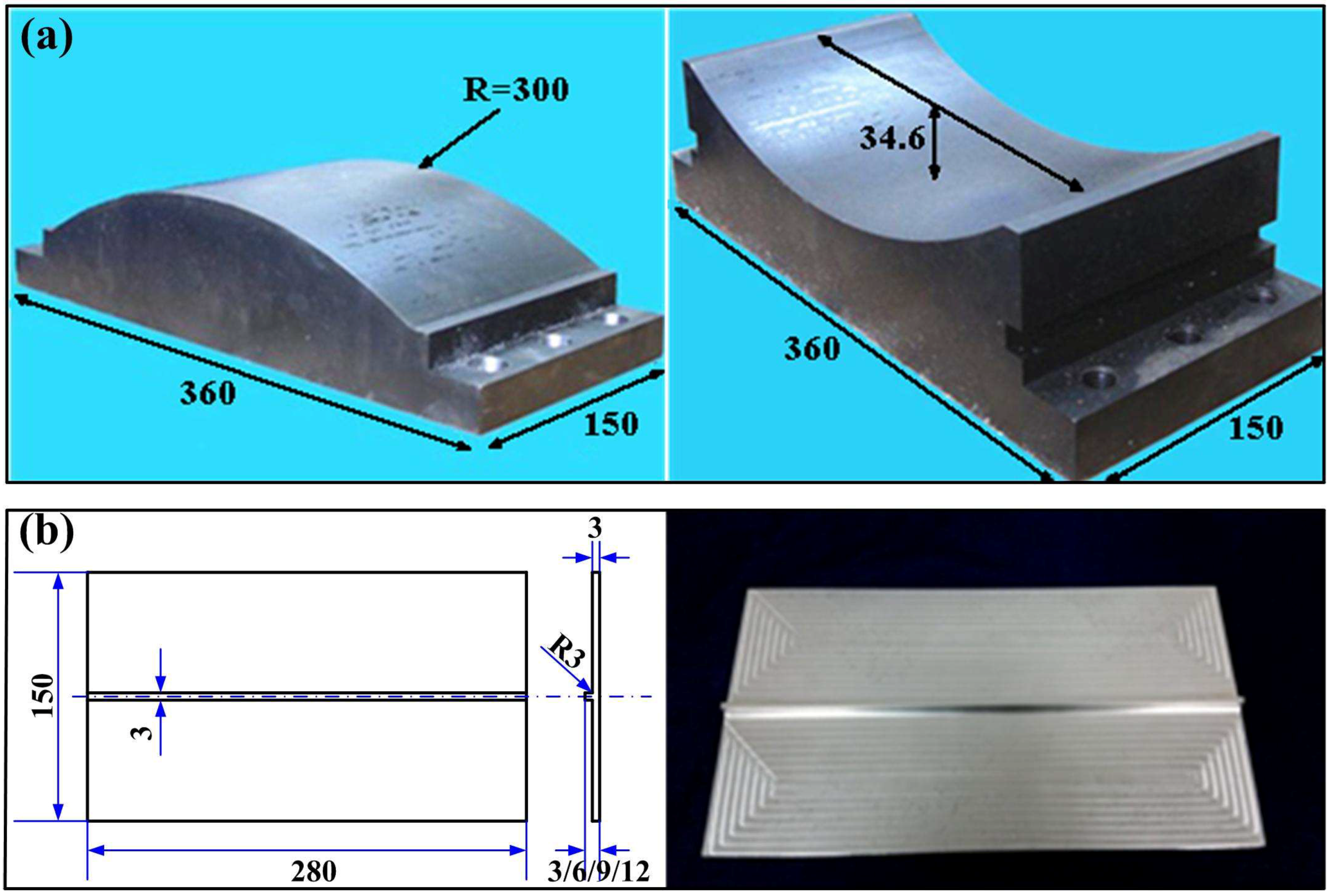
2.4. CAF Tests for Ribbed Panels

Figure 2 shows the geometries and the dimensions of the ribbed panels and the dies used in CAF tests. The thickness (t) of baseplate and rib is 3 mm, and the rib heights (h) are 0, 3, 6, and 9 mm. The ribbed panels were also machined out from the hot rolled plate by NC milling, and then the solution treated under 470 °C for 50 min, followed by water quenching, and their length direction was parallel to the rolling direction. In the assembly stage, the ribbed panel was placed between the upper and lower dies. In order to avoid the compression failure that was caused by the direct contact of the rib and upper die, some pure aluminum pads were placed around the ribs to fill the gap between the baseplate and upper die. The upper die was pressed down to fit the ribbed panel with the lower die completely, and this fitting was maintained using bolts at each end of the upper and lower dies. The whole set of device was placed in the aging furnace and was heated to 165 °C. After holding of 12 h, the device was removed from the furnace, and the ribbed panel was cooled and unloaded.

3. Creep Aging Behaviors with Damage Evolution

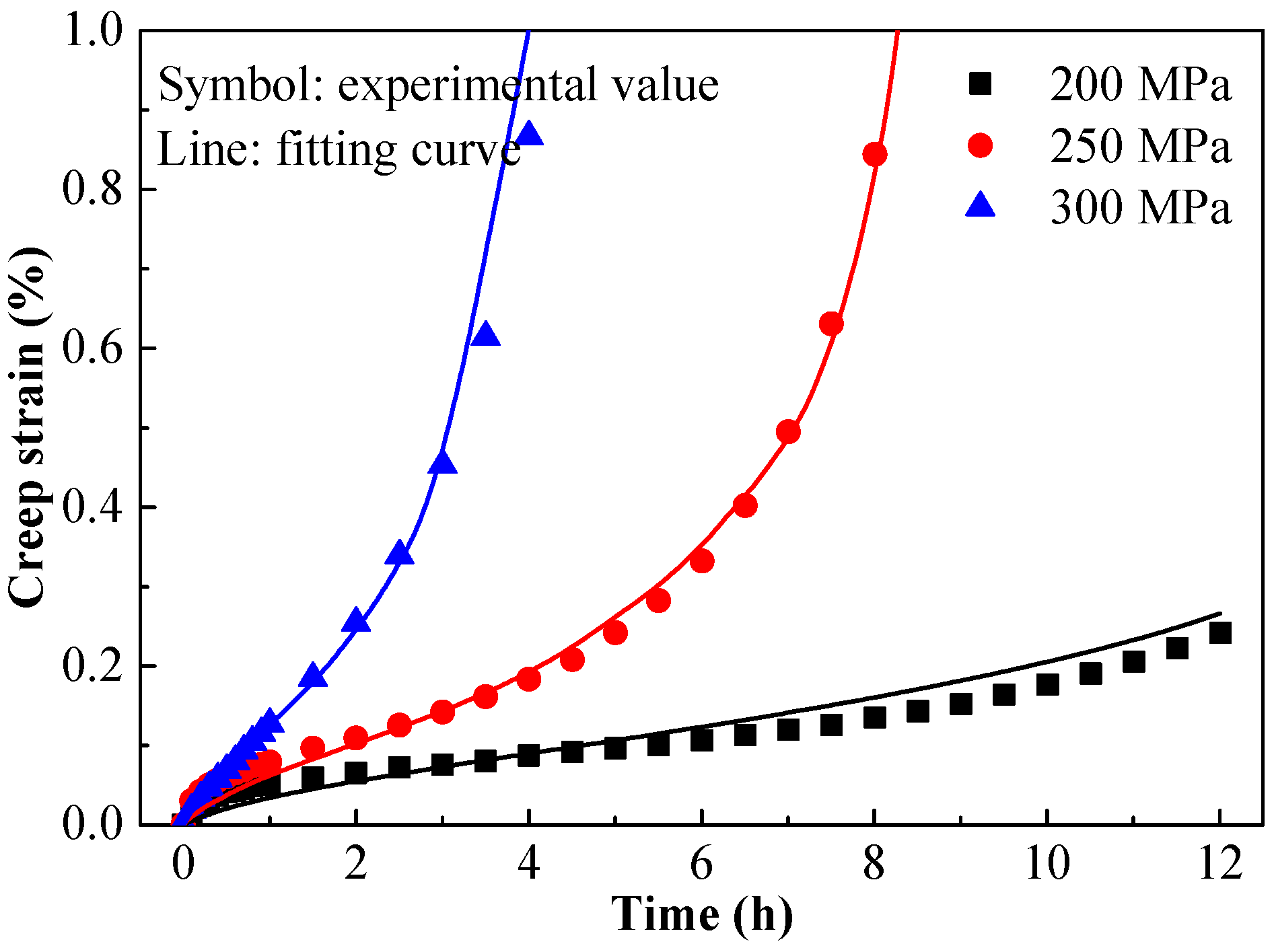
3.1. Creep Deformation
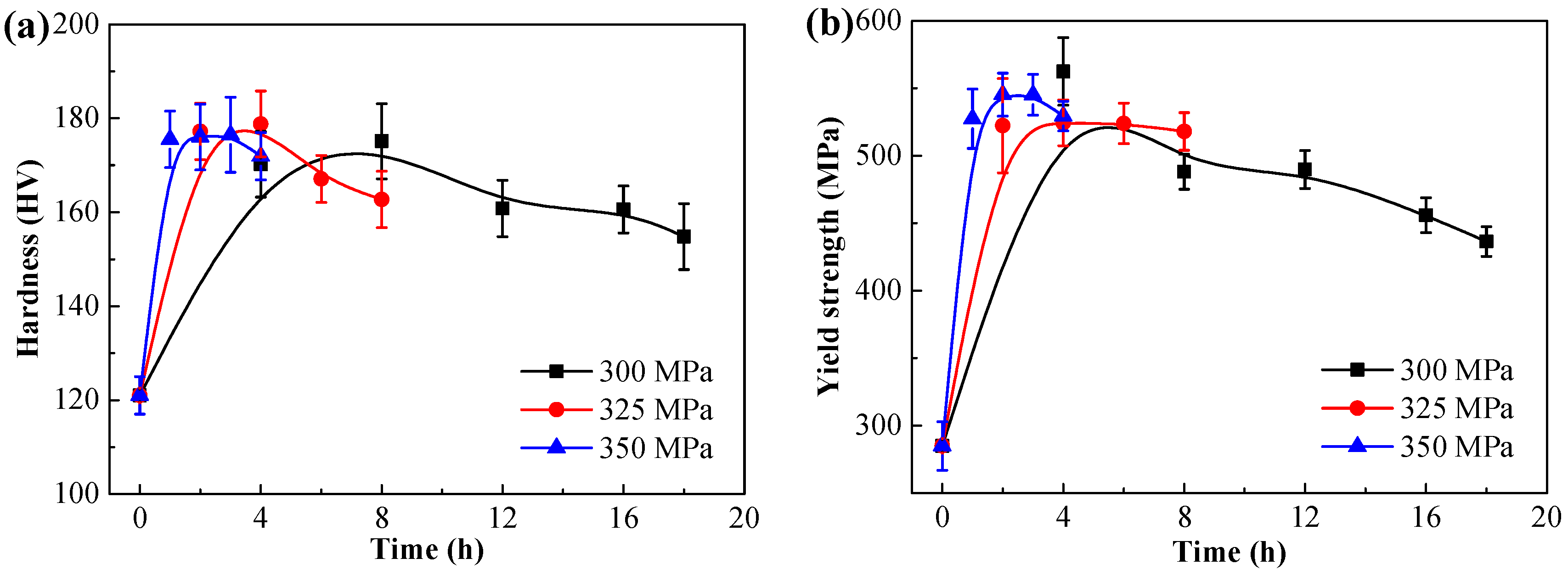
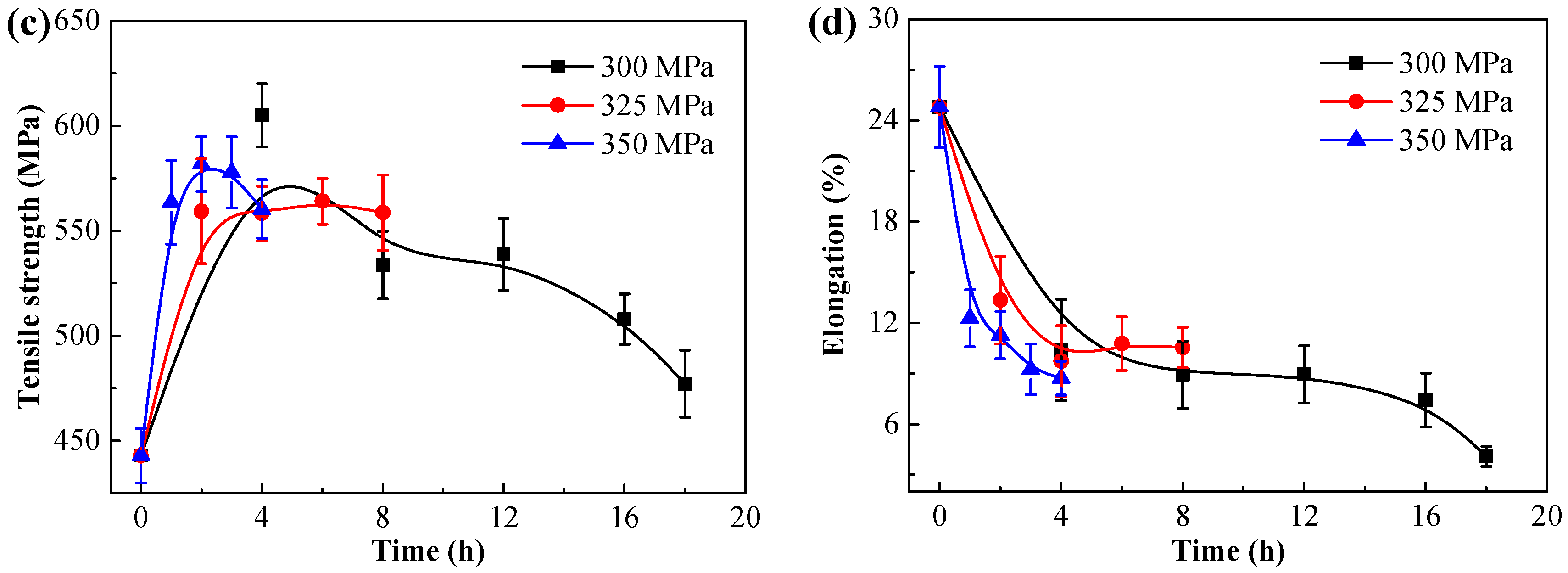
Figure 3 shows the creep strain and creep rate curves of AA7050 under 165 °C and various applied stresses. In the creep strain curves, it can be seen that the creep strain in the tertiary creep stage accounts for a large proportion of total creep strain. With the increase of applied stress, the steady creep stage and fracture time obviously shorten, but the total creep strain increases. In the creep rate curves, the typical three stages of creep deformation are presented clearly. The creep rate reduces sharply in the primary creep stage and it remains stable in the steady creep stage. Due to the occurrence of damage, the creep rate increases drastically after entering the tertiary creep stage, leading to the final fracture. With the increase of stress, the steady creep rate becomes larger, but the steady creep stage shortens and even disappears.

3.2. Age Hardening

Figure 4 shows the evolutions of mechanical properties of AA7050 during the creep aging tensile tests under 165 °C and different applied stresses, including hardness, YS, TS, and elongation. The mechanical strengths (hardness, YS and TS) increase firstly and then decrease with creep aging time. The higher the applied stress, the faster the mechanical strength improves, and the earlier the material obtains peak mechanical strength. This shows that the increase of the applied stress accelerates the age hardening. Guo et al. [21] verified the applied stress can promote the formation and growth of precipitates in an Al-Zn-Mg-Cu alloy. The detailed discussion will be carried out drawing on the microstructure observation below.
Based on the evolutions of mechanical properties, some creep aged specimens were selected to observe corresponding precipitate microstructures. The precipitation sequence of Al-Zn-Mg-Cu alloys has been confirmed as: supersaturated solid solution → GP zone → η’ phase → η phase [22]. Under the creep aging condition, the metastable η’ phase and stable η phase are the main precipitates to affect the mechanical strengths, and the difference of the hardening effect mainly depends on the size of the two precipitates. The small-sized η’ phase can only be cut by moving dislocation, which has a stronger hardening effect. While the η’ phase transforms into the big-sized η phase that can be bypassed by moving dislocation, the mechanical strengths will decrease. Therefore, they are not distinguished here.
Figure 5 shows the intragranular precipitates of creep aged AA7050 under 165 °C and 300 MPa for 2, 4 and 12 h, and 350 MPa for 3 h. Many fine and dispersive precipitates exist in the matrix of alloy after creep aging of 2 h under 300 MPa. It can be seen from the mechanical properties curves that the hardness and strength are rising at this time, indicating that the alloy has not yet obtained the peak strength, still in the under-aging temper. After creep aging of 4 h, the precipitates grow up obviously, and the peak strength appears, indicating that the alloy is in the peak-aging temper. With the further extension of creep aging time, the precipitates coarsen severely, so the alloy enters the over-aging temper and the mechanical strengths decrease. Under 350 MPa, although the precipitates are still small, the mechanical strengths have obviously decreased. This indicates that the cause of the decreasing mechanical strengths of the alloy is not over-aging, but the occurrence of damage.

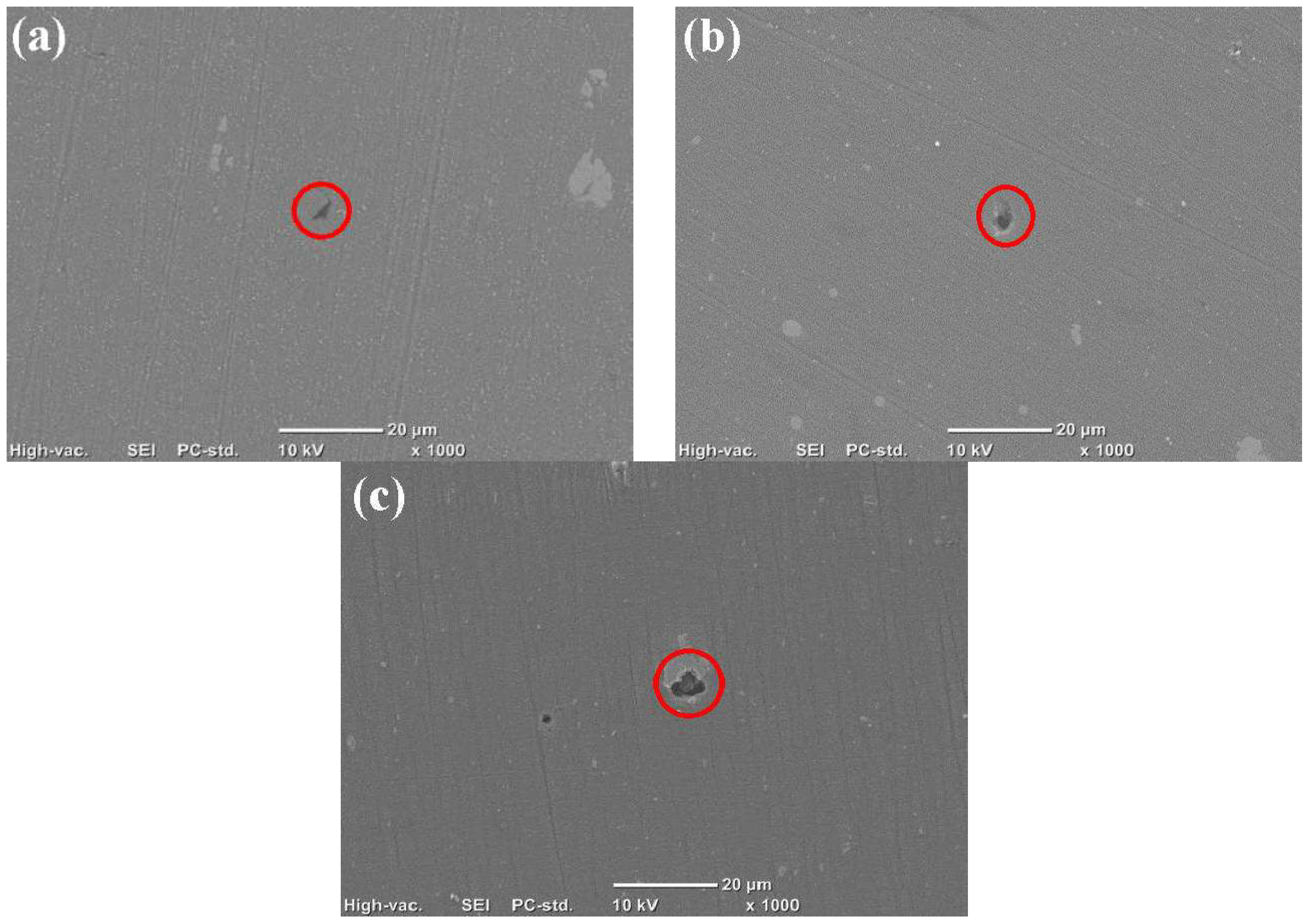
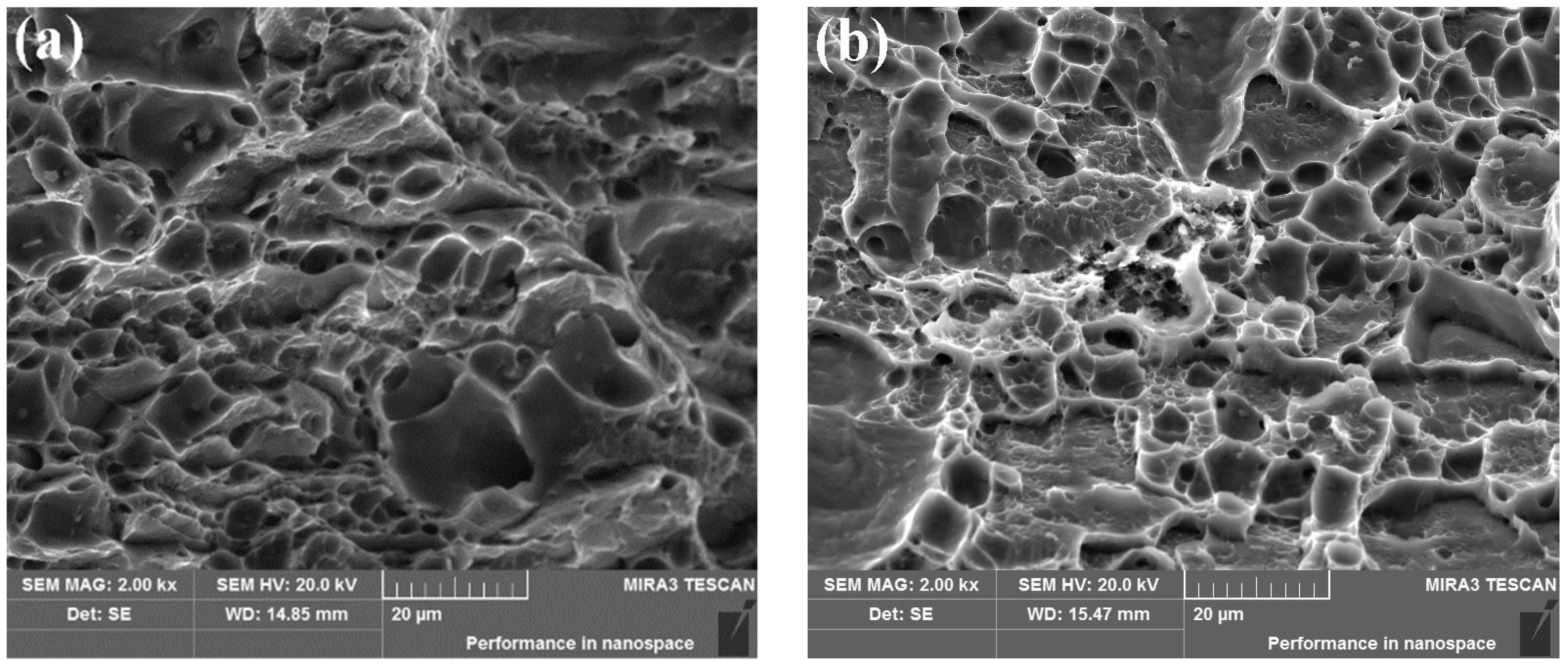
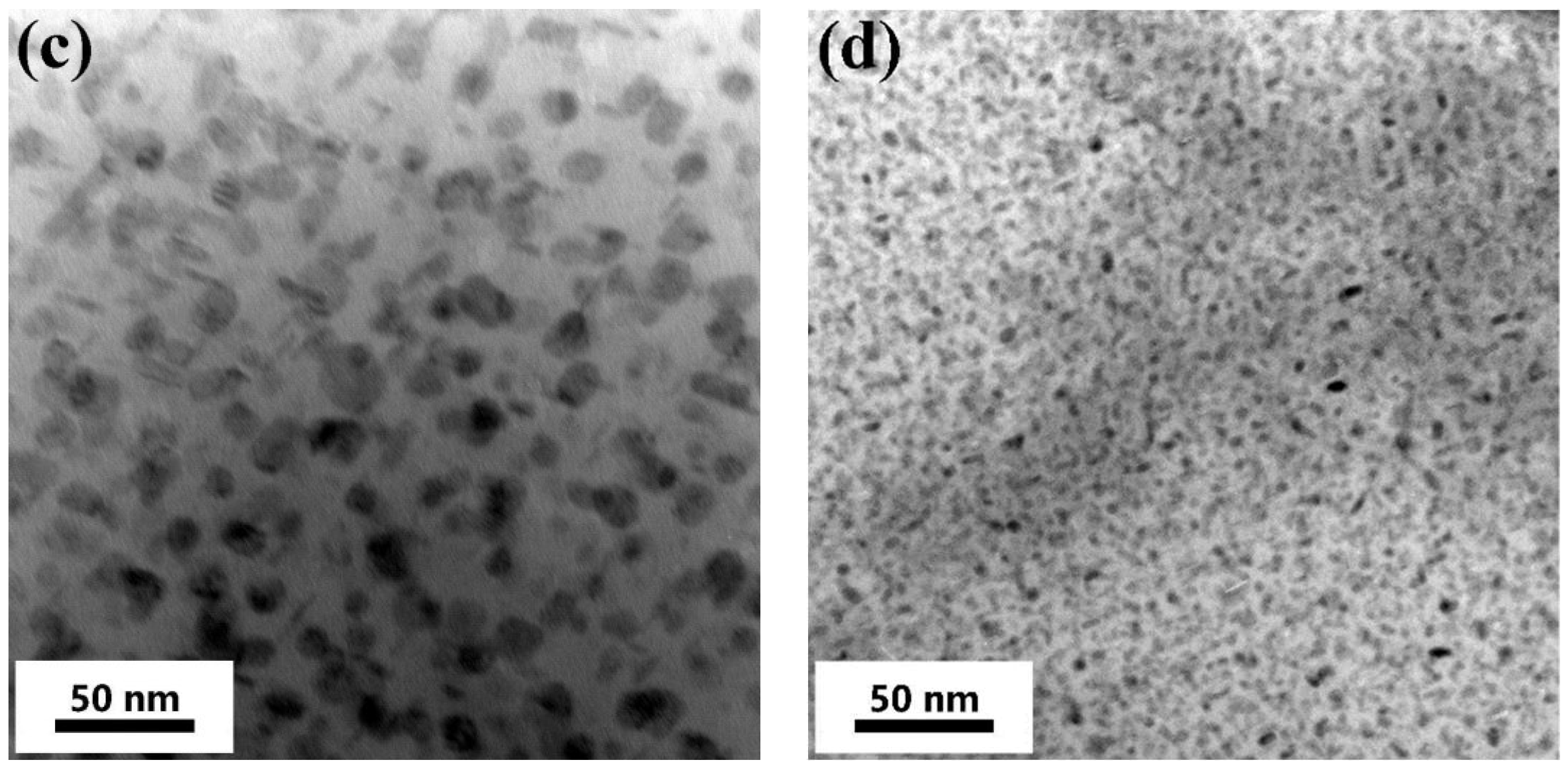
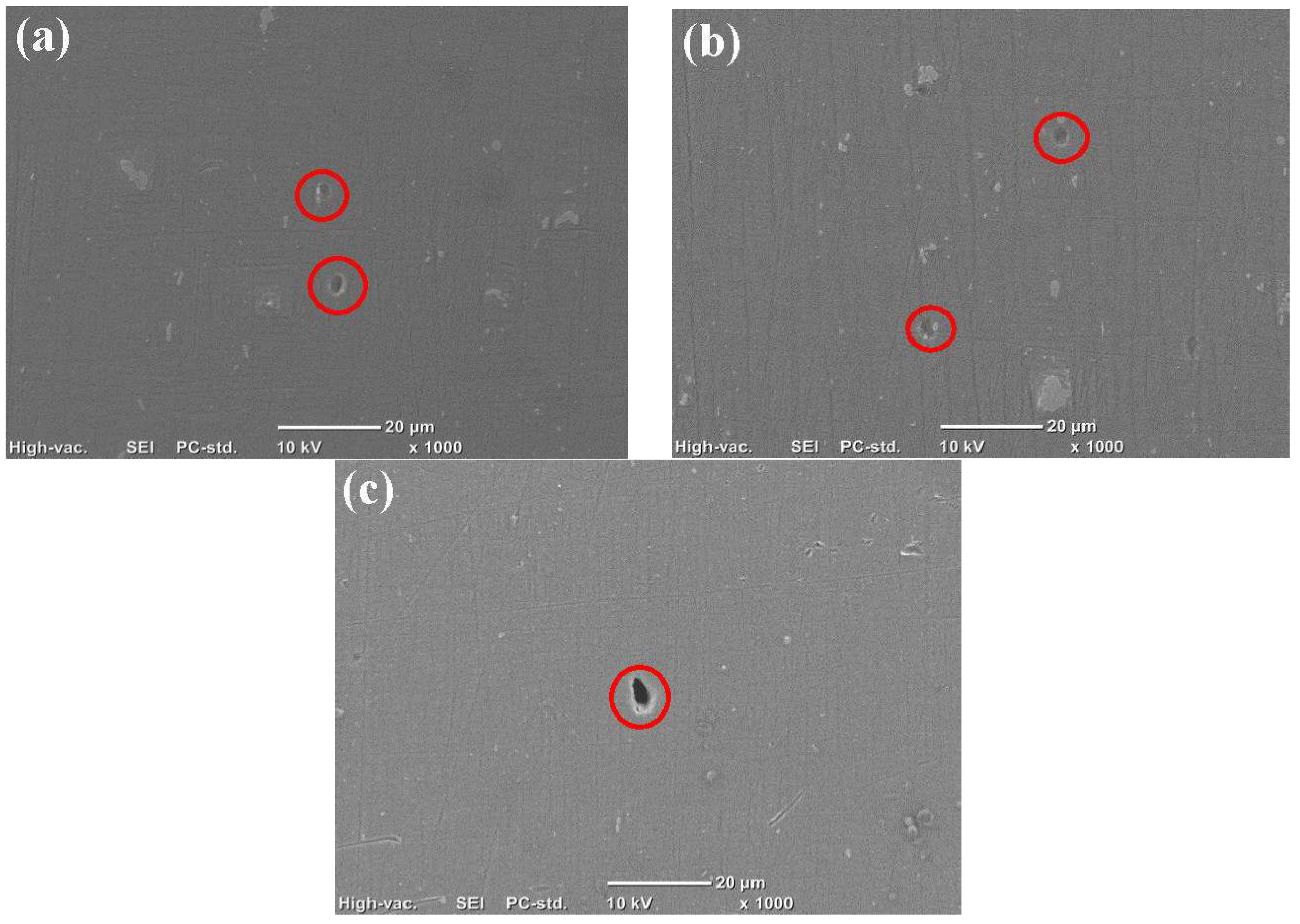
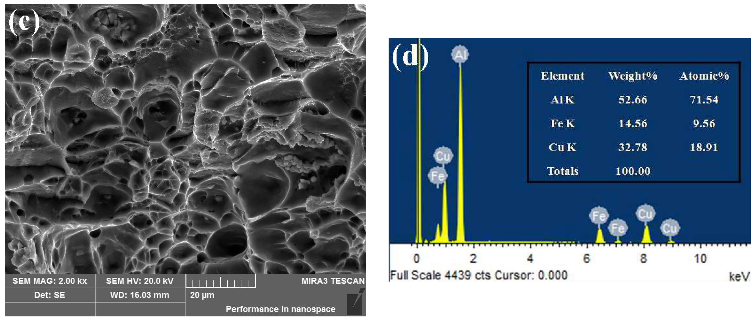
3.3. Damage Evolution

Figure 6 shows the evolution of microvoid in AA7050 during creep aging under 165 °C and 350 MPa. After creep aging of 1 h, the damage cavity appears due to the chipping and separating of the second phase from the matrix. As the creep proceeds, the microvoid gradually grows because it captures a large number of moving dislocations. When the microvoid becomes larger and larger and it eventually becomes a crack, the specimen fractures quickly after entering the tertiary creep stage.
Figure 7 shows the comparison of microvoids in AA7050 during the tertiary creep stage under 165 °C and different stress levels. The greater the applied stress, the bigger the microvoid. It is mentioned above that the size of microvoid gradually grows with the creep deformation, but the size of microvoids in the tertiary creep stage is very different under different stress levels. This indicates that the most important factor affecting the size of micrvoid is applied stress rather than creep time. The increase of stress significantly promotes the movement of dislocation, and then causes more dislocation to participate in the growth of the microvoid.
The specimens are eventually ruptured in the creep aging tensile tests, and obvious necking can be found near the fracture. The fracture surface is parallel to the maximum shear stress direction, and has an angle of 45° with the principal stress direction. This fracture mode can be summarized as ductile fracture.
Figure 8 shows the fracture morphologies of AA7050 during creep aging tensile tests under 165 °C and different stress levels. The fractures are spongy and are composed with dimples of different sizes and shear planes. Such this fracture mode is a typical ductile fracture [23]. With the increase of applied stress, the fracture mode gradually varies from shear fracture to microvoid coalescence fracture. The increasing stress is conducive to the generation of internal necking, and the shear between the matrix and microvoid is reduced. The stress has little effect on the dimple diameter, but the dimple deepens with the increase of stress. Some broken particles can be seen clearly in the dimples, and proved to be the insoluble second phase Al7Cu2Fe, which is a high temperature stable phase and will be dissolved above 500 °C. Stress concentration occurs around these second phases during creep deformation, and a large number of micro-cracks are produced, leading to the final fracture.
To further clarify the damage mechanism in creep aging process, the room temperature tensile fracture experiments were conducted on AA7050 with two states. Figure 9a shows the room temperature tensile fracture morphology of the alloy with solution temper, and Figure 9b represents that of the alloy creep that is aged under 165 °C and 300 MPa for 12 h. The alloy with solution temper has a comparatively high elongation, and there are a large number of shear planes in the fracture, showing a typical shear fracture. The room temperature tensile fracture of creep aged alloy has a lot of glide steps, showing a ductile fracture dominant by shear fracture. It can be seen that the difference of fracture mechanisms between room temperature tension and creep aging is because the production of damage microvoids during the creep aging process.

4. Material and Process Modeling

4.1. Calibration of CDM Based Constitutive Model

Kowalewski et al. [19] used a sinh function to describe the stress level dependence of creep rate, and introduced two damage state variables to characterize the tertiary creep softening. This CDM based equation set is expressed as:
d ε d t = A ( 1 ω ) n sinh [ B σ ( 1 H ) ( 1 φ ) ]
d H d t = h σ d ε d t ( 1 H H * )
d φ d t = K C 3 ( 1 φ ) 4
d ω d t = C d ε d t
n = [ B σ ( 1 H ) / ( 1 φ ) ] coth [ B σ ( 1 H ) / ( 1 φ ) ]
where A, B, C, h, H*, and KC are material constants, which can be divided into three groups: (a) h and H* characterize the primary creep; (b) A and B describe the secondary creep; and, (c) C and Kc represent the damage evolution. The parameter H reveals the influence of hardening in the early stage of creep, and its value varies from 0 to H*, where H* is the saturation value of H. This equation set contains two damage state variables to present the influence of softening in tertiary creep stage. The first variable ϕ reflects the effect of precipitation on the material mechanical property during the aging process, and its value varies from 0 to 1. The second variable ω describes the cavitation induced damage during creep process.
The determination of material constants is an important part for establishing an accurate constitutive model [24,25]. In this work, a simplified genetic algorithm (GA) is taken to determine the constitutive parameters. The error between experimental and calculated values of the creep strain ε is taken as the optimization objective function:
f ( ε ) = j = 1 n 1 i = 1 m j [ ( ε i j c ε i j e ) / ε i j e ] 2
where ε i j c and ε i j e represent the calculated and experimental values of creep strain, respectively. n1 is the number of experimental creep curves, and mj is the number of experimental data on the jth creep curve.
Fourth Order Gill Formula is selected as the numerical integration method for GA to solve the above problem. The GA parameters are defined as follows: population size 400, crossover probability 0.8, mutation probability 0.05, and iterative algebra 1500. The optimized constitutive parameters of AA7050 are obtained, as listed in Table 2. Figure 10 shows the comparison between experimental and calculated creep strains of AA7050 creep aged under 165 °C and different stresses. The well agreement indicates that the CDM based creep aging model is suitable for describing the creep aging behavior with damage.

4.2. FE Modeling for CAF of Ribbed Panels

The CDM based model has been implemented into commercial FE solver ABAQUS via a user-defined subroutine CREEP, and an implicit FE model has been developed for CAF of AA7050 ribbed panel. Figure 11 shows the FE models of ribbed panels and dies, and CAF simulation procedure. The 8-node tetrahedral reduced integral three-dimensional solid element (C3D8R) is used in FE modeling of the aluminum alloy panel. The mesh sizes on baseplate and rib are 5 mm × 5 mm × 1 mm and 5 mm × 1.5 mm × 1 mm, respectively. The concave die with bending radius of 300 mm is composed of rigid elements, and completely fixed throughout the forming process. Contact between the rigid die surface and the deformable aluminum panel is defined as a friction coefficient of 0.3. Since the panel is completely symmetrical, for convenience, 1/4 of the panel is taken as the research object in the subsequent discussion. A feature point located at the center of the upper surface of the rib is selected to analyze the simulation results. The whole simulation process is divided into three steps: (1) Loading: the pressure is gradually increased to 10 MPa, leading to the panel touch with the die completely; (2) Holding: the pressure is held for 12 h to maintain the fitting of panel and die; and, (3) Unloading: the pressure is removed. Table 3 lists the mechanical properties of the AA7050 with solution temper under 165 °C.

5. FE Simulation and Experimental Verification for CAF of Ribbed Panels

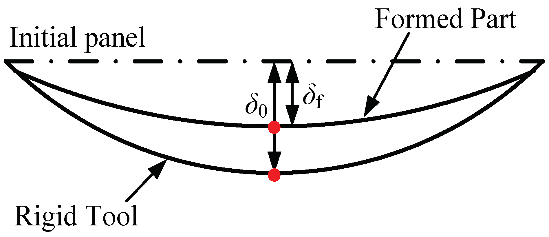
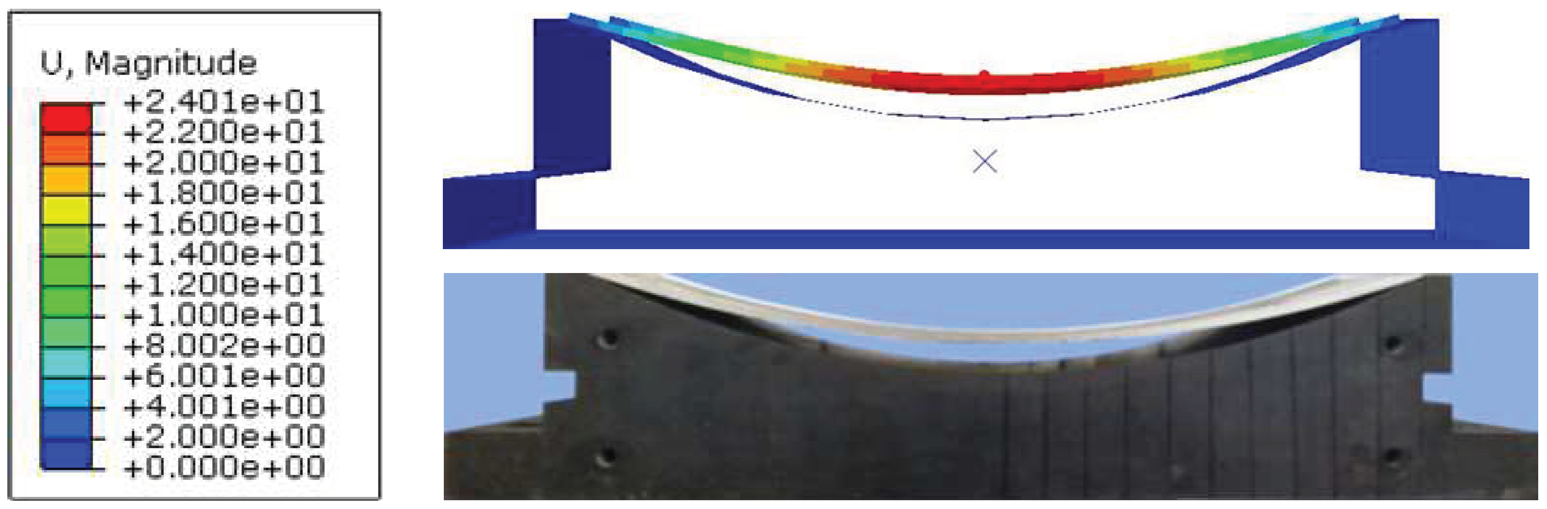
5.1. FE Model Validation Based on Springback

The deflection method is selected to measure the springback (S) as shown in Figure 12 according to Equation (7). δ0 is the initial deflection when the panel is attached to the die. δf is the final deflection after panel springback.
S ( δ ) = ( 1 δ f / δ 0 ) × 100 %
Figure 13 shows the predicted final deflection of AA7050 ribbed panel with h/t = 1 after springback and the corresponding experimental verification. In this case, δ0 is 34.60 mm, the predicted δf is 24.01 mm and corresponding experimental results is 23.72 mm. That is, the predicted and experimental S are 30.61% and 31.45%, and the error is only 2.67%. Table 4 lists the comparison between the experimental and predicted δf and S of AA7050 ribbed panels with different h/t. It can be seen that the rib limits the occurrence of springback, and the springback decreases with the increase of rib height. All of the errors are less than 3%, indicating that the FE model has satisfactory prediction accuracy.

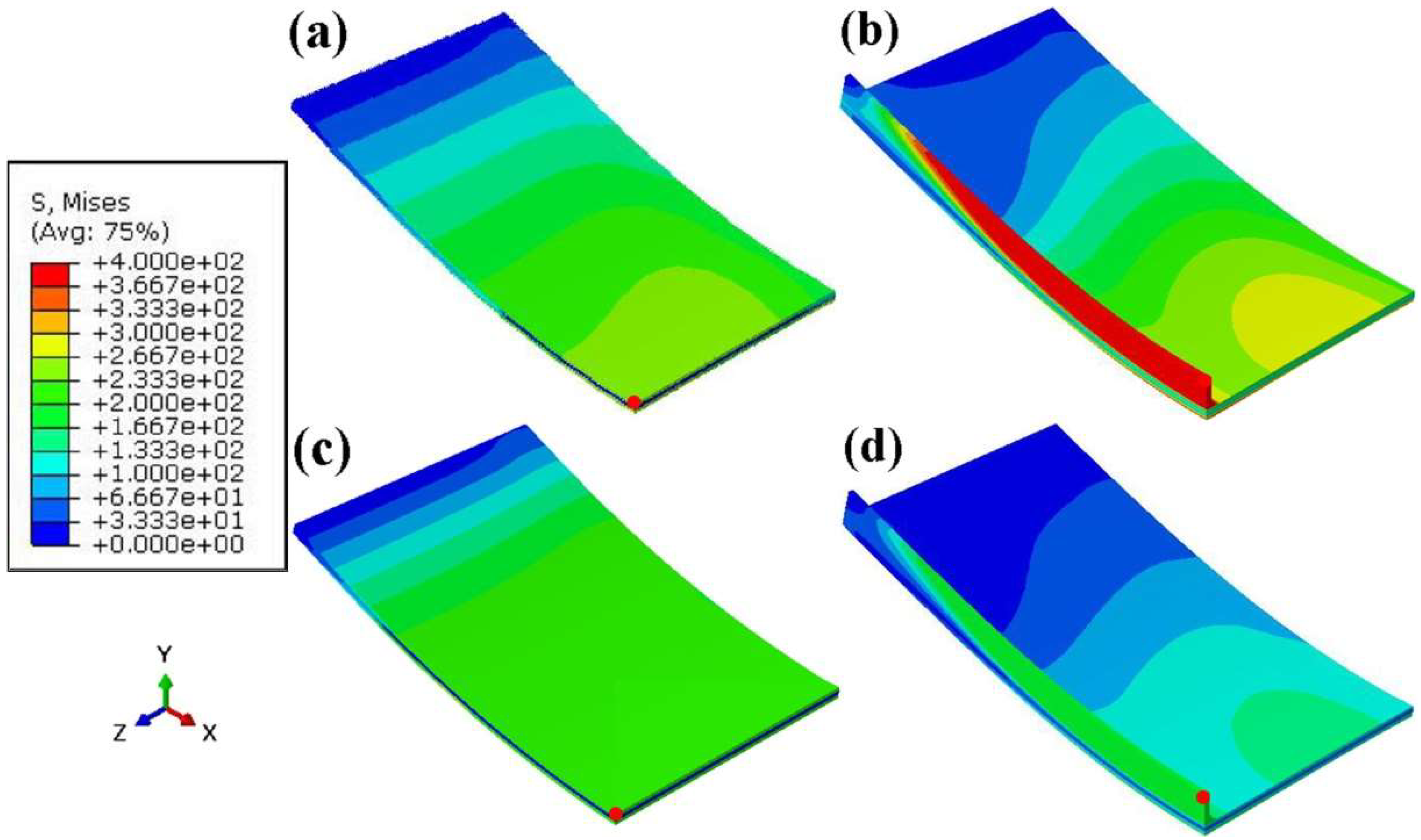
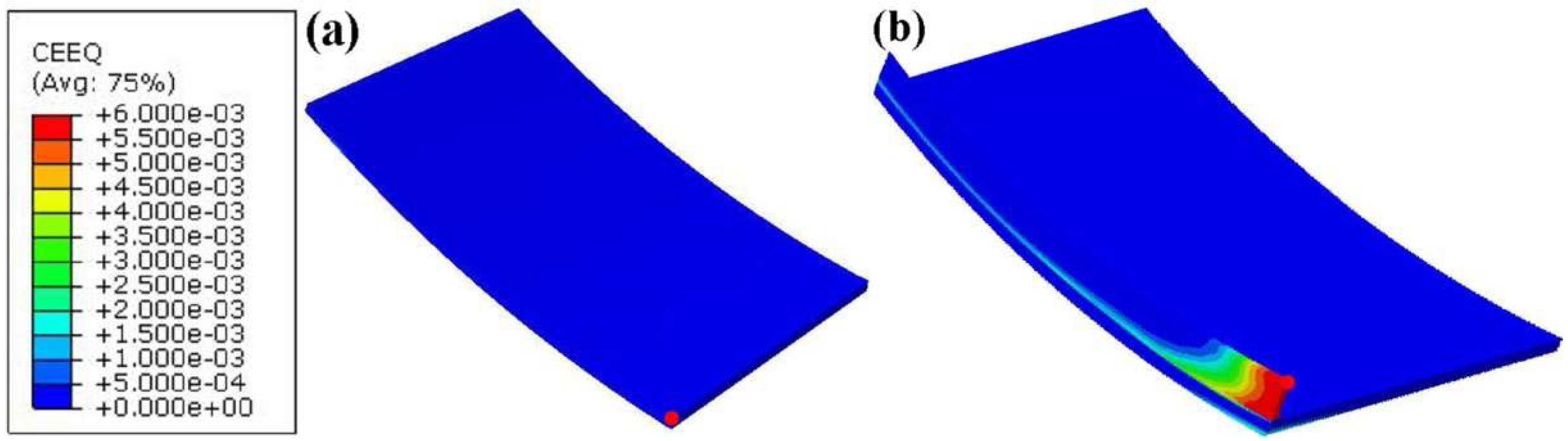
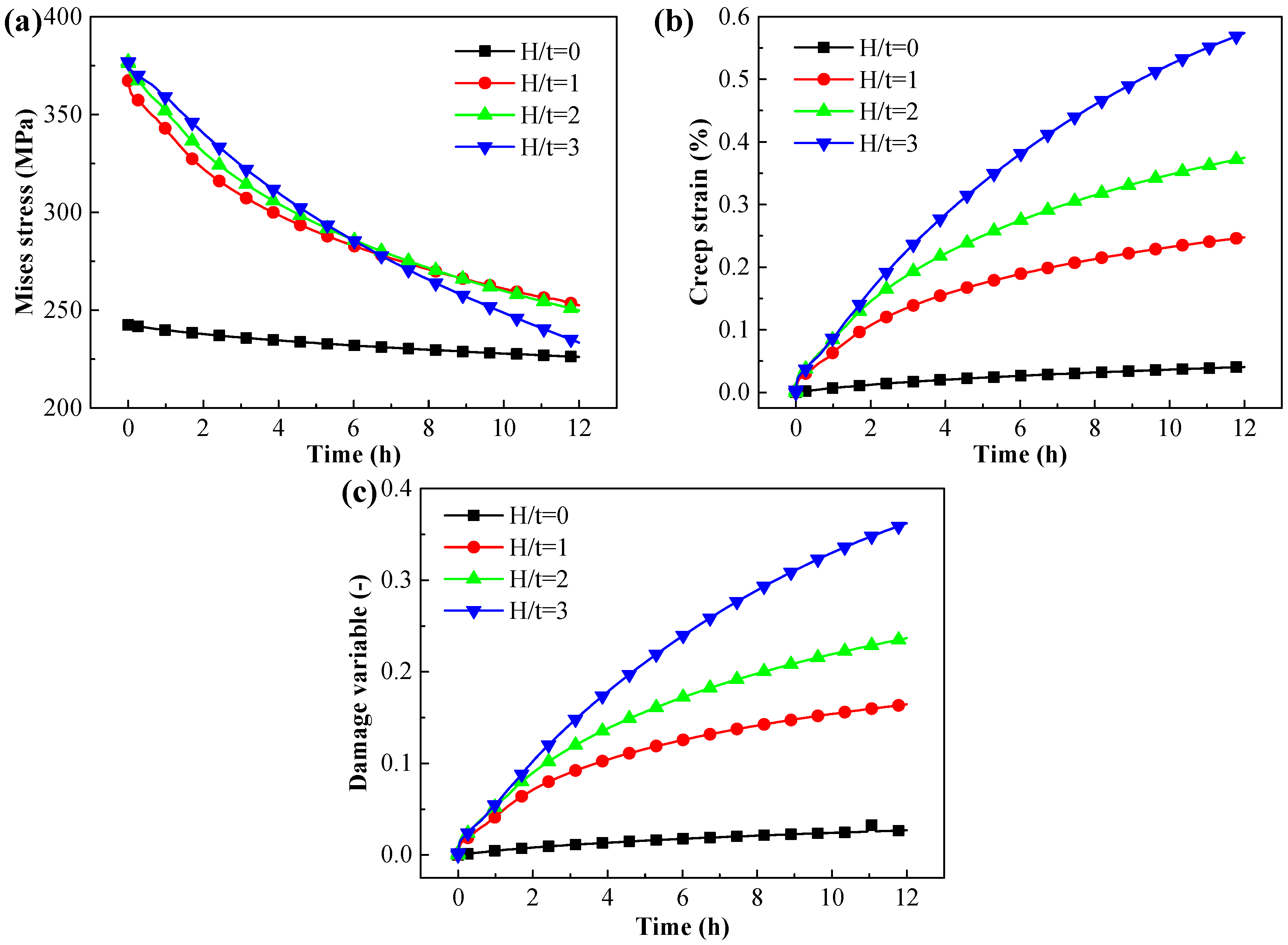
5.2. Evolutions of Stress, Strain and Damage

Figure 14 shows the Mises stress distribution of AA7050 ribbed panels with different h/t. The CAF process begins when the panels are attached to the die closely. At this point, the maximum Mises stress on the panel of h/t = 0 is 242 MPa, which is less than the yield strength of 284 MPa for AA7050 under 165 °C, while the maximum Mises stress on the panel of h/t = 3 is 377 MPa. It can be seen that there are severe stress concentration within and around the rib of the panel due to the high h/t. After CAF of 12 h, the maximum Mises stresses on both of the panels are reduced, which are 226 MPa of h/t = 0 and 228 MPa of h/t = 3, respectively. The stress relaxation phenomenon is more obvious on the panel with high h/t.
Figure 15 shows the creep strain distribution of AA7050 ribbed panels creep aged for 12 h. The creep deformation of the panel of h/t = 0 is homogeneous, and the maximum creep strain is 0.04%. For the panel of h/t = 3, the creep deformation is the most obvious in the middle of the rib, and gradually decreases toward the both ends and the surrounding area. The maximum creep strain for h/t = 3 is 0.59%, which is much bigger than that for h/t = 0. This is because the plastic deformation produced during loading stage is equivalent to a pre-deformation for the material, promoting the creep deformation during the creep aging stage [26].
Figure 16 shows the evolutions of the Mises stress, creep strain and damage variable on the feature point of AA7050 ribbed panels during CAF. All of the ribbed panels with different h/t show typical stress relaxation phenomena, and the higher the rib, the more obvious the relaxation. The creep strains increase with the creep time, but the creep rates decrease gradually. The higher the rib, the more serious the damage.

6. Conclusions

Taking 7050 aluminum alloy as the case material, combining experiment and simulation, the creep aging damage behavior of the alloy was studied. The major conclusions can be drawn, as follows:
(1)
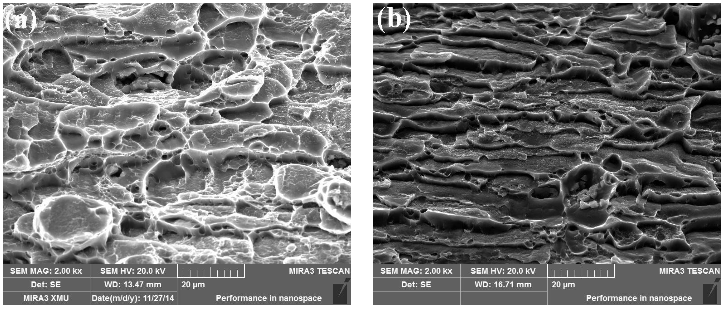
The effects of applied stress on the creep deformation, evolutions of precipitates and microvoids, mechanical property, and the damage mechanism were studied. The greater the applied stress, the bigger the creep strain, the faster the growth rates of precipitates and microvoids, the more rapid the decrease of mechanical property. The dominant mechanism of creep fracture changes from shear to microvoid coalescence with the increase of applied stress.
(2)
The CDM based creep aging constitutive model was calibrated, and the material constants were determined by GA. Two damage state variables were used to model the tertiary creep softening that is caused by the damage and over-aging. Then, the constitutive model was verified by comparison between the experimental and calculated creep strains, and the well-fitting results indicated that the model is suitable for describing the creep aging behavior with damage.
(3)
Implementing the creep aging model into ABAQUS solver via CREEP subroutine and combining the FE simulation and experiment, the CAF process of ribbed panels was studied. The creep damage takes place mainly on the bending rib, and with the increase of rib height, the creep deformation, and damage degree increase but the springback decreases.

Acknowledgments

The research is supported by the National Natural Science Foundation of China for Key Program (51235010), the National Science Fund for Excellent Young Scholars (51522509) the Marie Curie International Research Staff Exchange Scheme (IRSES, MatProFuture, project No.: 318968) within the 7th EC Framework Programme (FP7).

Author Contributions

Chao Lei performed the study and wrote the paper under the guidance of Heng Li; Nian Shi and Jin Fu assisted the experiments and modeling; Gaowei Zheng and Tianjun Bian assisted in editing the manuscript.

Conflicts of Interest

The authors declare no conflict of interest.

References

  1. Zhan, L.H.; Lin, J.G.; Dean, T.A. A review of the development of creep age forming: Experimentation, modelling and applications. Int. J. Mach. Tools Manuf. 2011, 51, 1–17. [Google Scholar] [CrossRef]
  2. Holman, M.C. Autoclave age forming large aluminum aircraft panels. J. Mech. Work. Technol. 1989, 20, 477–488. [Google Scholar] [CrossRef]
  3. Liu, L.F.; Zhan, L.H.; Li, W.K. Creep aging behavior characterization of 2219 aluminum alloy. Metals 2016, 6, 146. [Google Scholar] [CrossRef]
  4. Xu, Y.Q.; Zhan, L.H. Effect of creep aging process on microstructures and properties of the retrogressed Al–Zn–Mg–Cu alloy. Metals 2016, 6, 189. [Google Scholar] [CrossRef]
  5. Li, W.K.; Zhan, L.H.; Liu, L.F.; Xu, Y.Q. The effect of creep aging on the fatigue fracture behavior of 2524 aluminum alloy. Metals 2016, 6, 215. [Google Scholar] [CrossRef]
  6. Li, L.T.; Lin, Y.C.; Zhou, H.M.; Jiang, Y.Q. Modeling the high-temperature creep behaviors of 7075 and 2124 aluminum alloys by continuum damage mechanics model. Comput. Mater. Sci. 2013, 73, 72–78. [Google Scholar] [CrossRef]
  7. Arabi Jeshvaghani, R.; Emami, M.; Shahverdi, H.R.; Hadavi, S.M.M. Effects of time and temperature on the creep forming of 7075 aluminum alloy: Springback and mechanical properties. Mater. Sci. Eng. A 2011, 528, 8795–8799. [Google Scholar] [CrossRef]
  8. Arabi Jeshvaghani, R.; Shahverdi, H.R.; Hadavi, S.M.M. Investigation of the age hardening and operative deformation mechanism of 7075 aluminum alloy under creep forming. Mater. Sci. Eng. A 2012, 552, 172–178. [Google Scholar] [CrossRef]
  9. Lei, C.; Yang, H.; Li, H.; Shi, N.; Fu, J.; Zhan, L.H. Dependence of creep age formability on initial temper of an Al–Zn–Mg–Cu alloy. Chin. J. Aeronaut. 2016, 29, 1445–1454. [Google Scholar] [CrossRef]
  10. Lei, C.; Yang, H.; Li, H.; Shi, N.; Zhan, L.H. Dependences of microstructures and properties on initial tempers of creep aged 7050 aluminum alloy. J. Mater. Process. Technol. 2017, 239, 125–132. [Google Scholar] [CrossRef]
  11. Lei, C.; Li, H.; Zheng, G.W.; Fu, J. Thermal-mechanical loading sequences related creep aging behaviors of 7050 aluminum alloy. J. Alloys Compd. 2018, 731, 90–99. [Google Scholar] [CrossRef]
  12. Chen, J.F.; Zhen, L.; Jiang, J.T.; Yang, L.; Shao, W.Z.; Zhang, B.Y. Microstructures and mechanical properties of age-formed 7050 aluminum alloy. Mater. Sci. Eng. A 2012, 539, 115–123. [Google Scholar] [CrossRef]
  13. Chen, J.F.; Zou, L.C.; Li, Q.; Chen, Y.L. Microstructure evolution of 7050 Al alloy during age-forming. Mater. Charact. 2015, 102, 114–121. [Google Scholar] [CrossRef]
  14. Chen, J.F.; Frankel, G.S.; Jiang, J.T.; Shao, W.Z.; Zhen, L. Effect of age-forming on corrosion properties of an Al–Zn–Mg–Cu alloy. Mater. Corros. 2014, 65, 670–677. [Google Scholar] [CrossRef]
  15. Ho, K.C.; Lin, J.; Dean, T.A. Modelling of springback in creep forming thick aluminum sheets. Int. J. Plast. 2004, 20, 733–751. [Google Scholar] [CrossRef]
  16. Ho, K.C.; Lin, J.; Dean, T.A. Constitutive modelling of primary creep for age forming an aluminium alloy. J. Mater. Process. Technol. 2004, 153–154, 122–127. [Google Scholar] [CrossRef]
  17. Lam, A.C.L.; Shi, Z.S.; Yang, H.L.; Wan, L.; Davies, C.M.; Lin, J.G.; Zhou, S.J. Creep-age forming AA2219 plates with different stiffener designs and pre-form age conditions: Experimental and finite element studies. J. Mater. Process. Technol. 2015, 219, 155–163. [Google Scholar] [CrossRef]
  18. Yang, Y.L.; Zhan, L.H.; Shen, R.L.; Liu, J.; Li, X.C.; Huang, M.H.; He, D.Q.; Chang, Z.L.; Ma, Y.L.; Wan, L. Investigation on the creep-age forming of an integrally-stiffened AA2219 alloy plate: Experiment and modeling. Int. J. Adv. Manuf. Technol. 2017, 95, 2015–2025. [Google Scholar] [CrossRef]
  19. Kowalewski, Z.L.; Hayhurst, D.R.; Dyson, B.F. Mechanism-based creep constitutive equations for an aluminum alloy. J. Strain Anal. Eng. 1994, 29, 309–316. [Google Scholar] [CrossRef]
  20. Zheng, G.W.; Li, H.; Lei, C.; Fu, J.; Bian, T.J.; Yang, J.C. Natural aging behaviors and mechanisms of 7050 and 5A90 Al alloys: A comparative study. Mater. Sci. Eng. A 2018, 718, 157–164. [Google Scholar] [CrossRef]
  21. Guo, W.; Guo, J.Y.; Wang, J.D.; Yang, M.; Li, H.; Wen, X.Y.; Zhang, J.W. Evolution of precipitate microstructure during stress aging of an Al–Zn–Mg–Cu alloy. Mater. Sci. Eng. A 2015, 634, 167–175. [Google Scholar] [CrossRef]
  22. Sha, G.; Cerezo, A. Early-stage precipitation in Al–Zn–Mg–Cu alloy (7050). Acta Mater. 2004, 52, 4503–4516. [Google Scholar] [CrossRef]
  23. Li, H.; Fu, M.W.; Lu, J.; Yang, H. Ductile fracture: Experiments and computations. Int. J. Plast. 2011, 27, 147–180. [Google Scholar] [CrossRef]
  24. Lin, J.; Yang, J.B. GA-based multiple objective optimisation for determining viscoplastic constitutive equations for superplastic alloys. Int. J. Plast. 1999, 15, 1181–1196. [Google Scholar] [CrossRef]
  25. Li, B.; Lin, J.; Yao, X. A novel evolutionary algorithm for determining unified creep damage constitutive equations. Int. J. Mech. Sci. 2002, 44, 987–1002. [Google Scholar] [CrossRef]
  26. Yang, Y.L.; Zhan, L.H.; Shen, R.L.; Yin, X.N.; Li, X.C.; Li, W.K.; Huang, M.H.; He, D.Q. Effect of pre-deformation on creep age forming of 2219 aluminum alloy: Experimental and constitutive modelling. Mater. Sci. Eng. A 2017, 683, 227–235. [Google Scholar] [CrossRef]
Figure 1. Geometry and dimensions of creep aging test specimens (unit: mm).
Metals 08 00285 g001
Figure 2. Geometries and dimensions of (a) upper and lower dies and (b) ribbed panels (unit: mm).
Metals 08 00285 g002
Figure 3. Creep deformation behaviors of AA7050 during creep aging tensile tests under 165 °C and different stress levels: (a) creep strain curves; and, (b) creep rate curves.
Metals 08 00285 g003
Figure 4. Mechanical properties evolutions of AA7050 during creep aging tensile tests under 165 °C and different stress levels: (a) hardness; (b) yield strength; (c) tensile strength; and, (d) elongation.
Metals 08 00285 g004aMetals 08 00285 g004b
Figure 5. Transmission electron microscope (TEM) bright field images for intragranular precipitates of creep aged AA7050 under 165 °C and different stress levels: (a) 300 MPa for 2 h; (b) 300 MPa for 4 h; (c) 300 MPa for 12 h; and, (d) 350 MPa for 3 h.
Metals 08 00285 g005aMetals 08 00285 g005b
Figure 6. Scanning electron microscope (SEM) images for evolution of microvoid in AA7050 during creep aging under 165 °C and 350 MPa: (a) 1 h; (b) 2 h; and, (c) 3 h.
Metals 08 00285 g006
Figure 7. SEM images for comparison of microvoids in AA7050 during tertiary creep stage under 165 °C and different stress levels: (a) 300 MPa for 18 h; (b) 325 MPa for 8 h; and, (c) 350 MPa for 4 h.
Metals 08 00285 g007
Figure 8. SEM images for fracture morphologies of AA7050 during creep aging tensile tests under 165 °C and different stress levels: (a) 300 MPa; (b) 325 MPa; (c) 350 MPa; and, (d) component analysis of second phase particle.
Metals 08 00285 g008aMetals 08 00285 g008b
Figure 9. SEM images for room temperature tensile fracture morphologies of AA7050 with different states: (a) solution temper; and, (b) creep aged under 165 °C and 300 MPa for 12 h.
Metals 08 00285 g009
Figure 10. Comparison between experimental and calculated creep strains of AA7050.
Metals 08 00285 g010
Figure 11. FE models and creep age forming (CAF) simulation procedure.
Metals 08 00285 g011
Figure 12. Schematic diagram of springback measurement.
Metals 08 00285 g012
Figure 13. FE simulation and experimental verification based on springback of creep aged AA7050 ribbed panel with h/t = 1 (unit: mm).
Metals 08 00285 g013
Figure 14. Mises stress distribution of AA7050 ribbed panels: (a) h/t = 0, creep aged 0 h; (b) h/t = 3, creep aged 0 h; (c) h/t = 0, creep aged 12 h; and, (d) h/t = 3, creep aged 12 h.
Metals 08 00285 g014
Figure 15. Creep strain distribution of AA7050 ribbed panels creep aged for 12 h: (a) h/t = 0; and, (b) h/t = 3.
Metals 08 00285 g015
Figure 16. Evolutions of (a) Mises stress, (b) creep strain, and (c) damage variable on feature point of AA7050 ribbed panels.
Metals 08 00285 g016
Table 1. Nominal chemical composition of AA7050 (wt. %).
ZnMgCuZrSiFeTiMnAl
5.931.912.450.110.050.140.030.01Bal.
Table 2. Material constants of AA7050 in continuous damage mechanism (CDM) model.
A (h−1)B (MPa−1)h (MPa)H* (-)KC (h−1)C (-)
4.0001 × 10−80.03431.3127 × 1050.20004.0996 × 10−566.3721
Table 3. Mechanical property of AA7050 under 165 °C.
Heat Treatment ConditionYield Strength (MPa)Elastic Modulus (GPa)Poisson’s Ratio
Solution temper284.9062.240.33
Table 4. Comparison between experimental and predicted values of springback.
h/tPredicted ValueExperimental ValueError (%)
δf (mm)S (%)δf (mm)S (%)
019.5743.4419.1944.542.47
124.0130.6123.7231.452.67
227.1921.4226.9822.022.76
327.9319.2827.7319.862.91

