Article

Effects of Cryogenic Treatment on the Microstructure and Residual Stress of 7075 Aluminum Alloy

1
School of Material Science and Engineering, Beihang University, Beijing 100083, China
2
AVIC Chengdu Aircraft Industrial (Group) CO., LTD, Chengdu 610073, China
3
State Power Investment Corporation Research Institute, Beijing Future Science Park, South Area, Changping District, Beijing 102209, China
*
Author to whom correspondence should be addressed.
Metals 2018, 8(4), 273; https://doi.org/10.3390/met8040273
Submission received: 7 March 2018 / Revised: 9 April 2018 / Accepted: 9 April 2018 / Published: 16 April 2018

Abstract

:
The effect of cryogenic treatment (CT) on the microstructure, residual stress, and dimensional stability of 7075 aluminum alloy under temperatures of 0 °C, −60 °C, −120 °C, and −196 °C were studied, using optical microscopy (OM), scanning electron microscopy (SEM), transmission electron microscopy (TEM), an X-ray diffractometer, and an X-ray stress tester. The results indicated that CT can facilitate the dissolution of the coarse secondary phase into the α(Al) matrix, promote uniform distribution of Mg, Cu, Zn elements, and increase the density of fine secondary phases in the 7075 Al alloy. The CT can also induce the rotation of the α(Al) grain towards (200), through the processes of recovery and recrystallization. It was found that the residual stress was released, and a higher dimensional stability of the 7075 aluminum alloy was achieved, after CT. Experimental results demonstrated that the optimum CT temperature for the 7075 aluminum alloy is −120 °C.

Graphical Abstract

1. Introduction

Cryogenic treatment (CT) can significantly improve the microstructure and performance of materials, as an additional process to traditional heat treatment. In past decades, the effect of CT on steels has attracted tremendous attention, due to its important application potential. It is proposed that in a tool steel, the retained austenite (RA) transformed into martensite after CT, indicating that CT can reduce the amount of unstable RA and improve the structural stability of steel [1]. Similar research were performed by Lal et al. in the effect of CT on the wear resistance for tool and die steels, indicating that CT significantly improved tool life, due to the stabilization of carbides and microstructure [2]. According to research by Das et al., the effect of CT on secondary carbides and retained austenite are the governing mechanisms for the improved wear resistance of tool steels by CT [3]. In addition, CT could promote the precipitation of a high amount of secondary carbides, with a reduction in the average particle size, and homogenization of particle size distribution [4,5].
Thus far, a considerable effort has been devoted to studying the effect of CT on aluminum alloy. According to previous research, the residual stress could be caused by rapid cooling during the quenching process, and the residual stress in the aluminum alloy would degrade the mechanical properties of the alloy, causing premature failure [6,7]. In addition, residual stress can result in size change of a component [8]. In order to solve the problem of residual stress, various methods have been developed. For example, Nickola et al. reported that residual stress could be reduced by cold working, and Wu et al. found that electro-pulsing could be used to reduce residual stress [9,10]. However, cryogenic treatment is considered an effective approach, particularly for aluminum alloy. For example, the treatment combining CT and repaid heating can relieve about 71% of residual stress [11]. In addition, CT can improve the microstructure and mechanical performance of aluminum alloy [12,13,14,15]. As investigated by Volker et al., CT increased the fretting wear resistance and fretting fatigue life of aluminum alloy, owing to the formation of nano-scaled GP-zones, and Li et al. demonstrated the viability of this phase transformation by first-principles calculations [12,13]. It was proved that CT promoted the re-dissolution or dispersed precipitation of the GP-zones in the welded joints of 2024 Al alloy [13,15]. In addition, the mechanical properties of Al alloy can be successfully improved, and the influence of mechanical properties is strongly affected, by the material state before CT [13,14,16]. In a bibliographic review completed by Delprete and Baldissera [17], the microstructural influences of CT on microstructure and mechanical properties were analyzed comprehensively. Generally, the research of CT was performed by rapid cooling and heating, and few studies focused on CT with slow cooling. For 7075Al alloy, solid solution treatment can result in high residual stress in the alloy, which can result in degradation of its mechanical performance.
In present work, in order to optimize the mechanical performance of 7075 Al alloy, the microstructure, residual stress, and dimensional stability of alloy after CT were systematically investigated. The relaxation mechanism of residual stress at different temperatures is discussed.

2. Materials and Methods

The material used in this study was cold-rolled 7075Al plate, with a thickness of 3 mm, whose chemical composition is listed in Table 1. The sample with dimensions 100 mm × 100 mm × 3 mm for cryogenic treatment was prepared by wire-electrode cutting. Cryogenic treatment with different parameters was applied to this plate.
The CT processes are shown in Table 2. All the aluminum alloy specimens were subjected to solution treatment, at a temperature of 466 °C for 3600 seconds, then water-quenched to room temperature. In order to confirm the effects of different CT temperatures on the microstructure and residual stress of 7075Al, the samples were treated at different CT target temperatures of 0 °C, −60 °C, −120 °C, and −196 °C. The CT procedures were as follows:
  • the water-quenched specimens were placed into the CT equipment and slowly cooled down from room temperature to the target temperatures, with a cooling rate of 3 °C/min;
  • the specimens were held at target temperature for 2 h;
  • the specimens were taken out from the equipment and left in open air, until their temperatures reached room temperature.
After CT, the specimens undertook two-stage aging at 107 °C for 6 h, and 163 °C for 18 h. In addition, to clarify the effect of two CT process on 7075Al, the CT procedures were repeated, as mentioned above, after the first CT process, and then two-stage aging was utilized to treat the samples similarly.
After these treatments, observations under optical microscopy (OM) (DMLM, Leica, Buffalo Grove, IL, USA), scanning electron microscopy (SEM) (JSM-6010, JOEL, Akishima, Japan), and transmission electron microscopy (TEM) (JEM2100F, JEOL, Akishima, Japan) were carried out, to analyze the microstructure of the 7075 aluminum alloy. The characterization of the microstructure was carried out at the rolling surface. The samples for OM and SEM were ground with abrasive paper and then successively polished with 2.5, 1.5, and 0.5 μm diamond suspensions. The samples were etched using a solution composed of 2.5% HNO3 + 1.5% HCl + 1.0% HF + 95% H2O before observation. TEM foils were prepared by ion-beam thinning techniques, using a Gattan-691 precision ion polishing system with liquid-nitrogen cooling. TEM observations of precipitates were performed on selected samples, using a JEM2100F transmission electron microscope operating at 200 kV. An X-ray diffraction (XRD) (D/max2200PC, Rigaku, Beijing China) was employed to obtain the XRD diffraction pattern, operated at 40 kV with Cu Kα radiation and a scanning speed of 4°/min. Residual stress was measured by an X-ray stress tester (X-350A, ST Co.Ltd, Handan, China), operated at 28 Kv with Cr Kα radiation. The XRD analysis was performed at room temperature, with the ψ of 0°, 24.2°, 35.3°, and 45°. The samples prepared for residual stress were polished before the solid solution treatment, and the residual stress was measured at the center of the polished surface. The polishing was finished before the quenching process. There were five parallel samples of residual stress for every heat treatment. The dimensional stability was characterized by the rate of change of the annular opening size through the circular opening method (Figure 1) [18]. The rate of change was determined by the formula (ΔL/L) × 100%, in which L is the original opening length, and ΔL is the incremental change in length with aging time. The rate of change of every treatment was obtained through the average value of three parallel samples. The circular rings for the circular opening samples were processed before the quenching process, and sliced after the two-stage aging treatment.

3. Results and Discussion

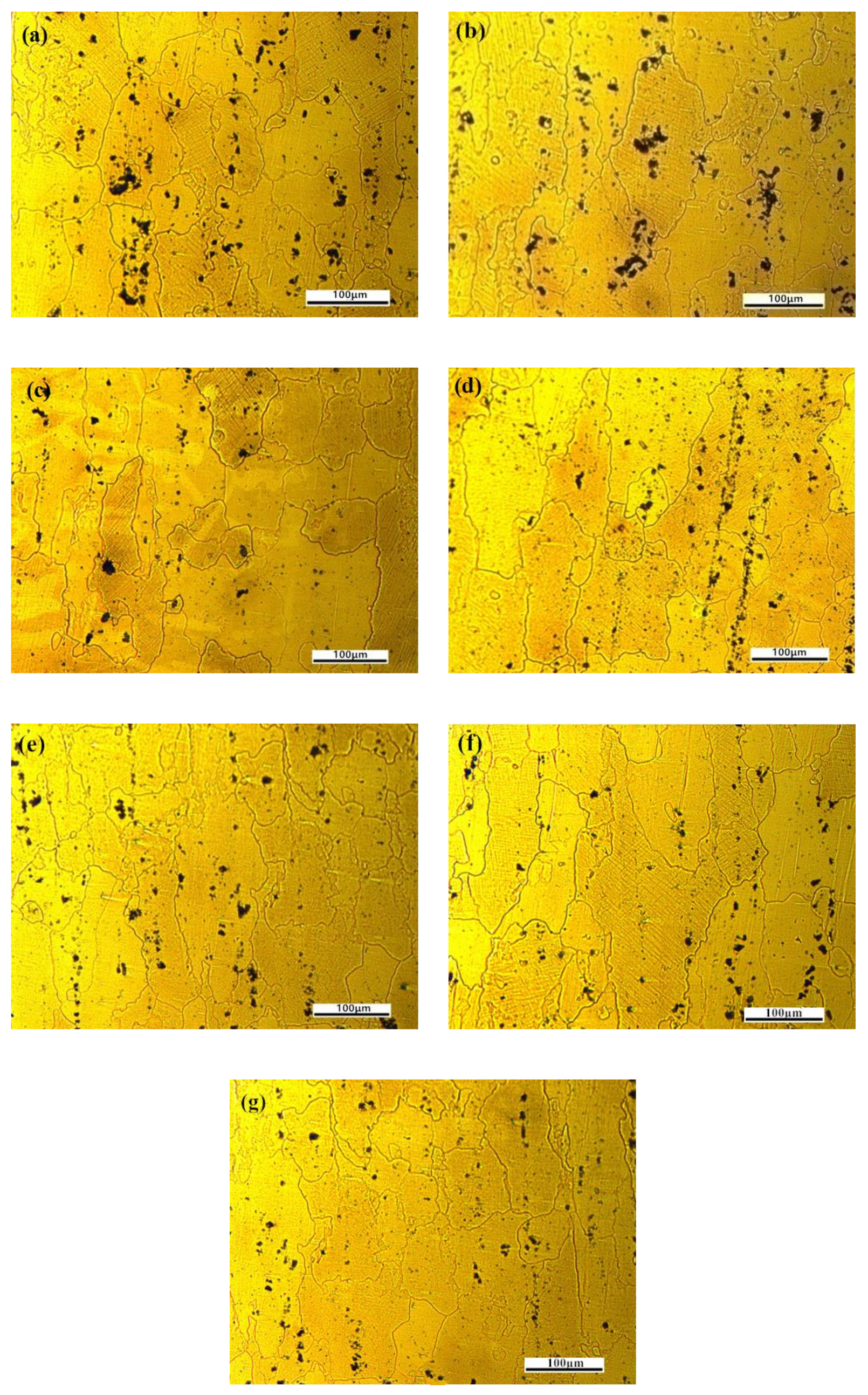
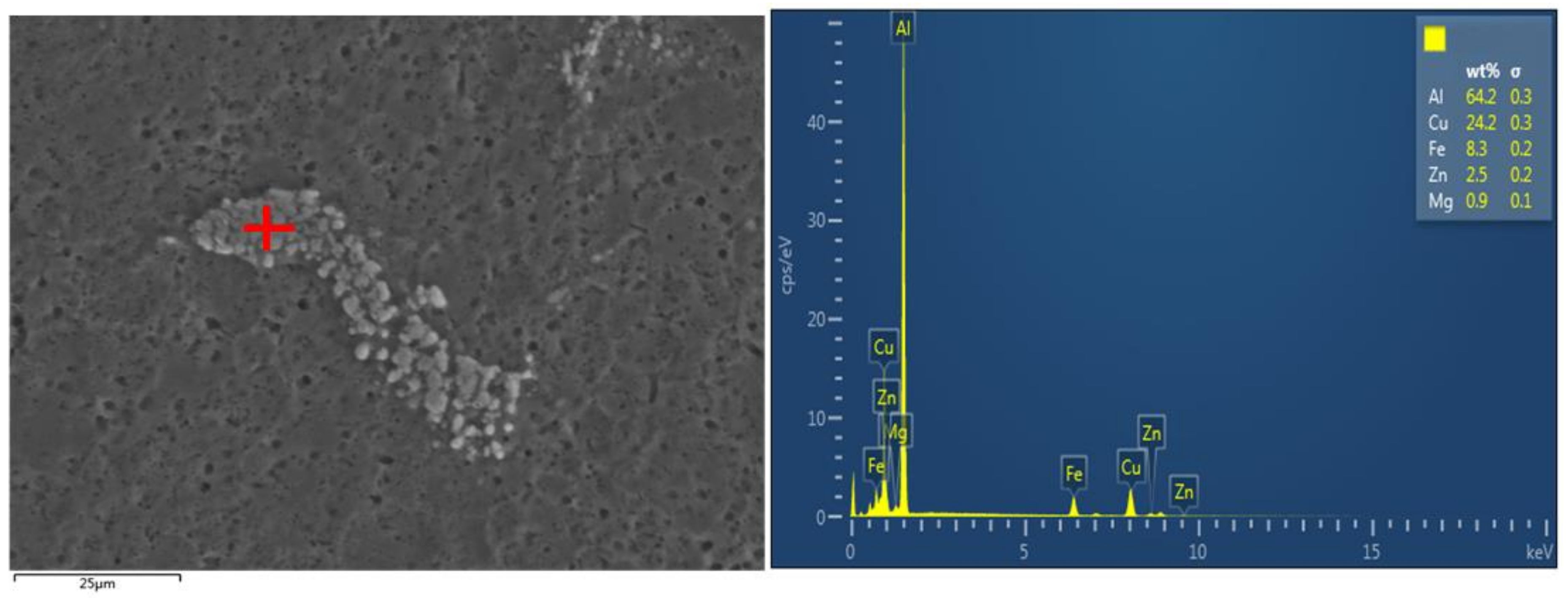
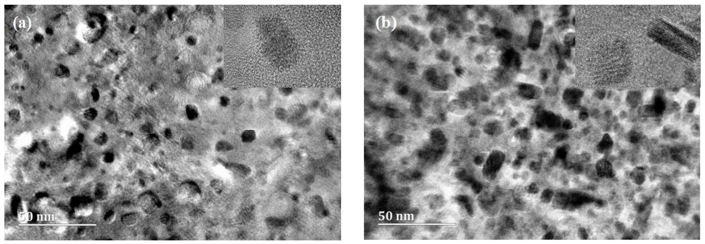
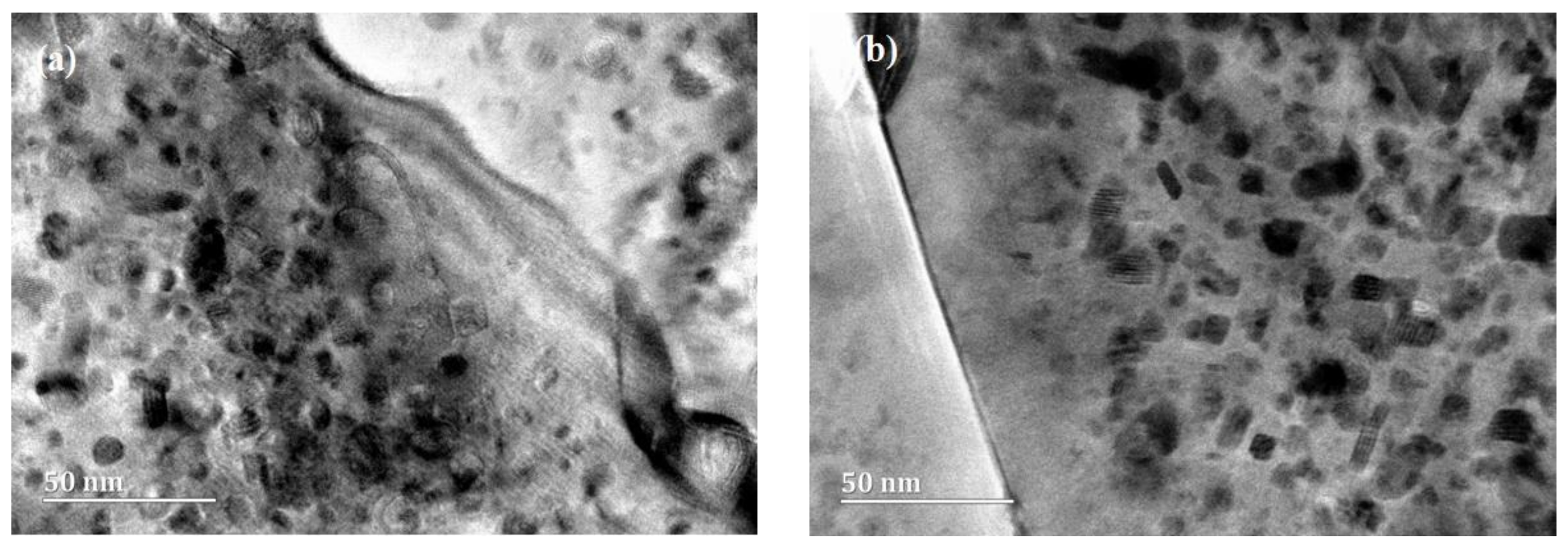
3.1. Effect of Cryogenic Treatment (CT) on the Microstructure of 7075 Aluminum Alloy

Figure 2a shows the microstructure of sample A without CT. It can be seen that there is a high prevalence of coarse secondary phases (apparent as dark areas) dispersed in the α(Al) matrix of the alloy. Figure 3 shows the result of energy dispersive spectroscopy (EDS) analysis for the coarse secondary phase, which indicates that the elements in the coarse secondary phase are Al, Cu, Zn, Mg, and Fe. According to previous research by Xu et al., these coarse secondary phases were the eutectic compounds Al7Cu2Fe, CuMgAl2, and MgZn2, respectively [19]. These eutectic compounds consumed a large number of alloying elements, which reduced the formation and precipitation of small particles in the alloy during the aging process. Hence, alloy with a large amount of coarse secondary phases may have relative low strength, and cracks may occur. This will cause the mechanical properties to degrade. Thus, CT can be used to improve the performance of the alloy, due to the content reduction of the coarse secondary phase. Figure 2b–e display the microstructures of samples B, C, D, and E, respectively. The results indicated that the size and amount of the dark, coarse, secondary phase decreased after CT, and that procedure D minimized the content of the coarse secondary phase.
It is most likely that the change in the density and size of the coarse secondary phase was induced by the dissolution of alloy elements from the coarse secondary phase into the α(Al) matrix. According to the research of Xu et al., the dislocation was induced by high stress, due to structural shrinkage and the different expansion coefficients of the different phases during the process of CT [20]. There is an obvious distinction between the thermal expansion coefficients of the α(Al) matrix and coarse precipitates. During CT, the α(Al) matrix around coarse precipitates undergoes severe plastic deformation, caused by the discordant change of volume, and a significant increase in dislocation density. Dislocations generate a different path for the diffusion of alloying elements. In addition, the gradient of concentration between the coarse secondary phase and α(Al) matrix provides a driving force for atomic migration. Therefore, CT can facilitate the dissolution of the coarse secondary phase into the α(Al) matrix, through short-range diffusion under low temperature conditions. Figure 2f,g shows the microstructures of samples F and G, which had undergone multiple cryogenic treatments at –60 °C and −120 °C, respectively. Comparing Figure 2c,f and Figure 2d,g, there are no significant variations in coarse precipitations after multiple cryogenic treatments.
To gain information on the presence of the secondary phase with high spatial resolution, TEM analysis was performed, with the results shown in Figure 4. A large number of fine secondary phase particles, which measure about 5 nm, are uniformly distributed in the grains of both samples, both with and without CT. While the size of these fine secondary phase particles did not change with CT, it is evident that the density of the particles increased significantly after CT. This is in contrast to the coarse secondary phase, whose density decreasing after the CT process, as shown in Figure 2.
Figure 5a,b displays the distributions of fine particles adjacent to the α(Al) matrix grain boundaries, for samples A and D, respectively. However, CT did not cause an obvious difference in grain boundary precipitates. According to the research of Feng et al., precipitate nucleation mostly occurred at the dislocations, and was heterogeneous during the artificial aging process [21]. Ratchev et al. found that the increasing dislocation density before artificial aging could enhance the heterogeneous nucleation sites [22]. The CT process caused shrinkage under a low temperature-induced, local plastic deformation, and increased dislocation density. In the subsequent artificial aging process, the density of precipitates was increased by the higher number of nucleation points.
Figure 6 shows the X-ray diffraction pattern of the 7075 alloys before and after different heat treatments. The characteristic peaks (shown in Figure 6) correspond to (111), (200), (220), and (311) reflection planes of α(Al). It can be seen that no new peaks appeared after the treatment processes, which indicates that no new phases were formed. Although the positions of the diffraction peaks in the x-axis did not change after CT, the height (intensity) of the peaks did change. Taking the diffraction peak intensity of the (200) plane as 100, the variations in relative diffraction peak intensity, corresponding to the other planes, after different treatments, are presented in Table 3. The diffraction peak (200) has obvious enhancement as the cryogenic temperature decreased, and reached a maximum in sample D. Meanwhile, the relative intensities of the diffraction peaks (111), (220), and (311) decreased as the cryogenic temperature decreased.
The changes in diffraction peak intensities indicate that CT can induce grain rotation from other orientations to (200). During the CT process, a large number of dislocations and sub-grains are activated, due to the stress resulting from the volume shrinkage effect. Phase recovery and recrystallization would occur during the warming-up process from the cryogenic temperature, which may induce grain rotation to the orientation of (200).

3.2. Effect of Cryogenic Treatment (CT) on the Residual Stress and Dimensional Stability of 7075 Alloys

During the quenching process, the steep temperature gradient in the sample was induced by the difference of cooling speed between the surface and center of the specimen. When the temperature of the sample surface layer cooled down to room temperature, the temperature at the center is still high. As the temperature of the center material decreased, its volume tended to reduce, while the surface layer suppressed the shrinkage of the center. The volume difference was removed through the elastic deformation of the surface layer and inner material. Under the elastic state, the volume shrinkage of the surface layer was induced by shrinkage stress from the inner material, and resulted in pressure between the grains of the surface layer. Therefore, the sample was distorted by compressive stress in the surface layer. Meanwhile, residual tensile stress in the inner material was caused by tensile elastic deformation, which was induced by tensile stress from the surface layer. The sample deformation after the quenching process is shown in Figure 7. In summary, the residual stress is dependent on the volume difference, i.e., the larger the volume difference, the higher the residual stress.
The residual stress ratio between the samples, with and without CT, is commonly used to measure the effect of CT on the residual stress states of alloys. The residual stress ratios of the samples are shown in Figure 8. It can be seen that the residual stress ratio decreased significantly after CT, and the lowest residual stress ratio was obtained at the CT temperature of −120 °C. As the results showed, the residual stress ratios of the samples after multiple (two) CT treatments were not obviously different to those of the single CT samples.
The influencing mechanism of CT on the residual stress has not been fully explained so far. When the sample is quenched to room temperature, the residual stress will be generated by compression in the surface layer. During the CT process after quenching, the grains in the surface layer will contract due to the lower temperature, which will release the compressive stress, resulting in reduced residual stress. Therefore, the residual stress decreases with decreased CT temperature. When the CT temperature is very low, however, the difference in the deformation between the matrix and the precipitates, due to the difference between their thermal expansion coefficients, will become more significant. When warming up from the CT temperature to room temperature, greater residual stress between the matrix and precipitates is generated. These two opposing effects of CT on residual stress will result in a minimum residual stress value at a certain CT temperature. In this work, the temperature corresponding to the minimum residual stress is −120 °C.
The residual stress release can cause dimensional variation in the Al alloys. In the present work, the open ring method was applied to evaluate the dimensional stability of 7075 alloy. The dimensional stability after different CT temperatures was measured by the dimensional variation rate ((ΔL/L) × 100), in which L is the original opening length, and the ΔL is the incremental change in opening length with aging time. Figure 9 shows that the dimensional variation rate of samples increased rapidly at the early stage, from week one to week five, and then leveled out. It can be seen that the lowest dimensional variation rate (13.3%) was obtained in sample D (treated at −120 °C), which corresponds to the low residual stress result in Figure 8. This indicates that the dimensional variation rate and the residual stress have a similar variation tendency, which implies that CT can improve the dimensional stability, through reducing residual stress.
As the most widely-used method to reduce the residual stresses of aluminum alloys, conventional CT is performed by immersing quenched parts in liquid nitrogen at −196 °C, followed by rapid heating in boiling water or high velocity steam. However, this technique is associated with some drawbacks, for instance, the high cost of consuming liquid nitrogen, and cracks or deformation, caused by uneven cooling and heating during the cooling and heating processing, for the parts with a complex shape or large size [11]. In this novel CT process, a good effect is obtained by CT performed under an optimal CT temperature, with a slow cooling process. The difficulty of controlling the uniformity of cooling and heating was solved by using slow cooling, and omitting rapid-heating processes. In addition, the omission of rapid heating will simplify the CT process and equipment. In conclusion, this CT process is more applicable and cheaper, compared with conventional CT. The improved CT process is more practical for parts that require thin-walls, a cavity, and are large in size.

4. Conclusions

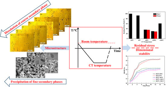
  • Cryogenic treatment (CT) can not only facilitate the dissolution of the coarse secondary phase into the α(Al) matrix of the 7075 Al alloy, but also promotes the precipitation of fine secondary phase particles.
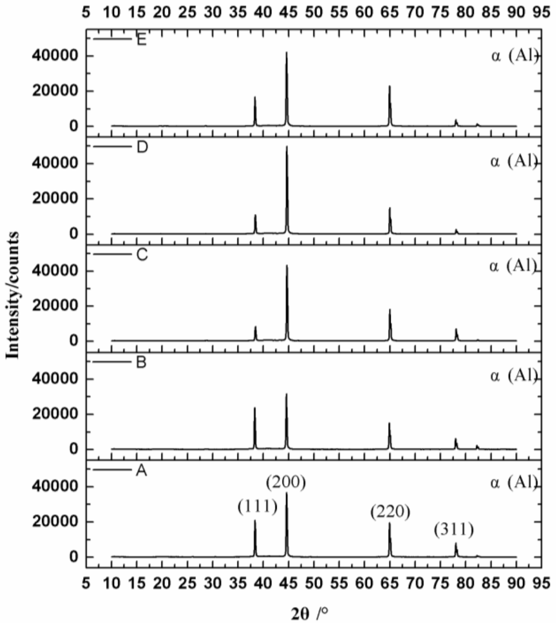
  • XRD analysis indicates that CT can result in rotation of the α(Al) grains towards the preferred (200) orientation, due to recovery and recrystallization during the following heating process from the CT temperature to room temperature.
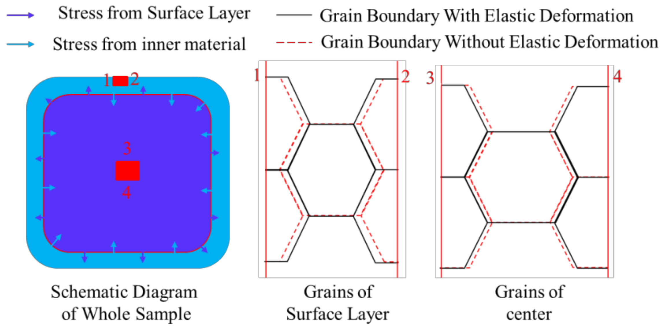
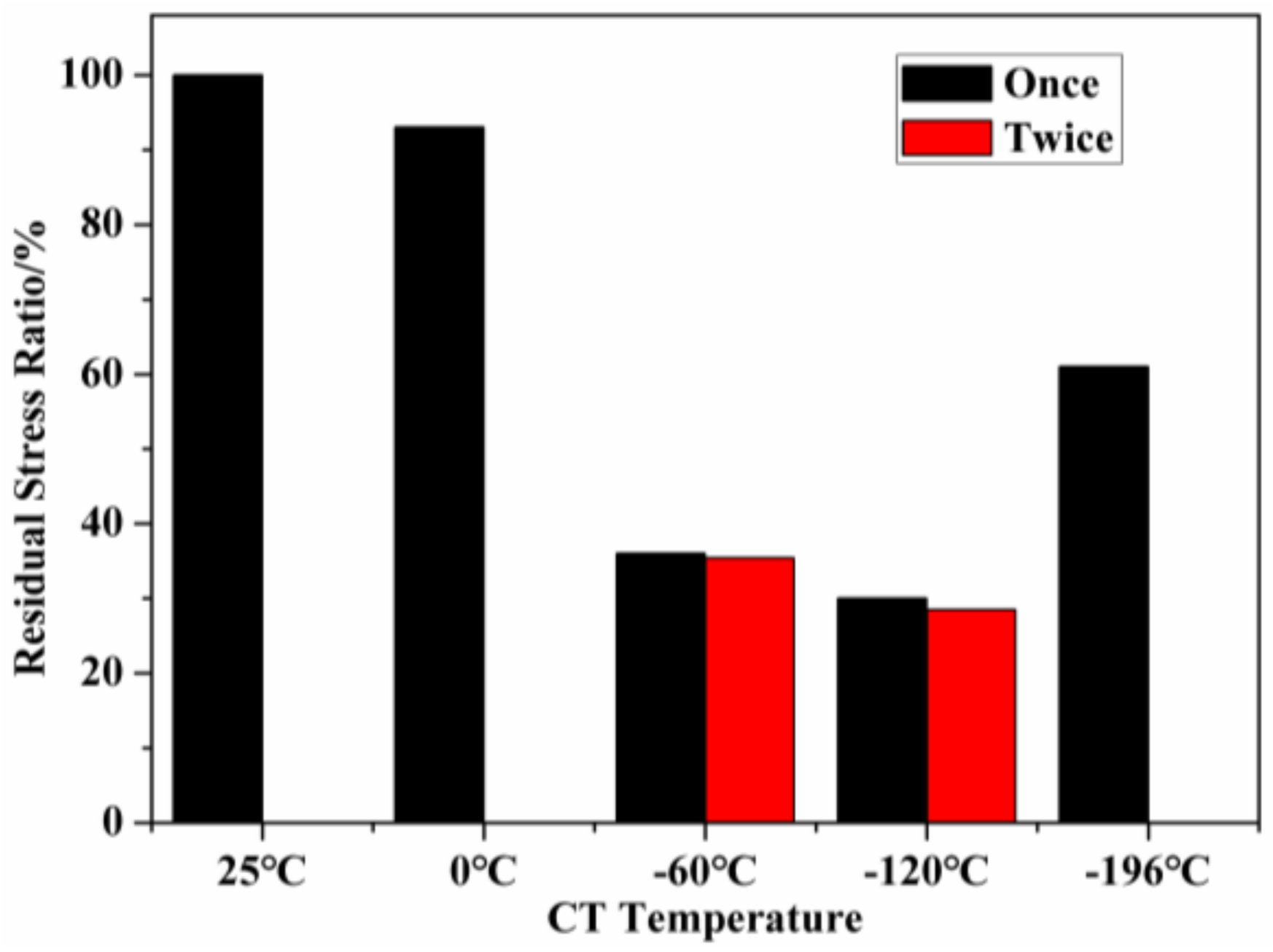
  • The residual stress of 7075 alloy can be significantly reduced by CT. The lowest residual stress rate (about 30%) was obtained for the sample that was treated at −120 °C.
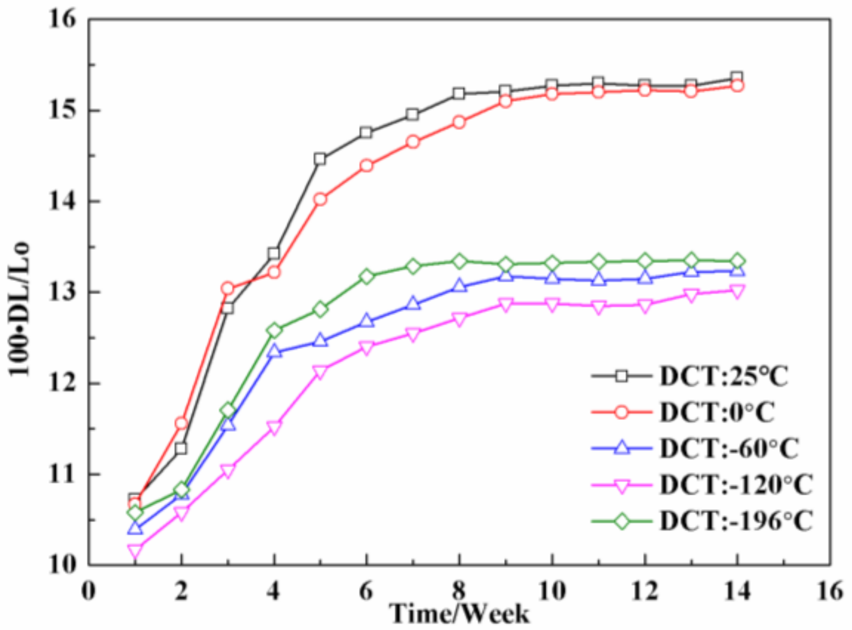
  • CT can improve the dimensional stability of the 7075 alloy through lowering the residual stress. The optimal dimensional stability for 7075 alloy was obtained at a CT temperature of −120 °C.

Acknowledgments

The authors wish to express thanks for financial support from the AVIC Chengdu Aircraft Industrial (Group) Co., Ltd.

Author Contributions

Lijun Wei performed the experiments, analyzed the data and wrote the paper; Linbin Zheng did optimize the research plan and revise the paper; Dawei Wang analyzed the data and revised the paper; Haisheng Li made the diagram and graph, and revised the paper; Di Xie made the diagram and graph; Fan Ye operated experiments and revised the paper; Ruokang Song collected the data and revised the paper; Gang Zheng researched literature and revised the paper; Sujun Wu improved the paper idea, analyzed the data and mechanism, and also revised the paper.

Conflicts of Interest

The authors declare no conflict of interest.

References

  1. Li, S.L.; Deng, L.H.; Wu, X.C.; Min, Y.A.; Wang, H.B. Influence of deep cryogenic treatment on microstructure and evaluation by internal friction of a tool steel. Cryogenics 2010, 50, 754–758. [Google Scholar] [CrossRef]
  2. Lal, D.M.; Renganarayanan, S.; Kalanidhi, A. Cryogenic treatment to augment wear resistance of tool and die steels. Cryogenics 2001, 41, 149–155. [Google Scholar]
  3. Das, D.; Dutta, A.K.; Ray, K.K. Correlation of microstructure with wear behavior of deep cryogenically treated AISI D2 steel. Wear 2009, 267, 1371–1380. [Google Scholar] [CrossRef]
  4. Stratton, P. Optimising nano-carbide precipitation in tool steels. Mater. Sci. Eng. A 2007, 449, 809–812. [Google Scholar] [CrossRef]
  5. Stratton, P.; Graf, M. The effect of deep cold induced nano-carbides on the wear of case hardened components. Cryogenics 2009, 49, 346–349. [Google Scholar] [CrossRef]
  6. Becker, R.; Karabin, M.E.; Liu, J.C.; Smelser, R.E. Distortion and residual stress in quenched aluminum bars. J. Appl. Mech. 1996, 63, 699–705. [Google Scholar] [CrossRef]
  7. Koc, M.; Culp, J.; Altan, T. Prediction of residual stresses in quenched aluminum blocks and their reduction through cold working processes. J. Mater. Process. Technol. 2006, 174, 342–354. [Google Scholar] [CrossRef]
  8. Lados, D.A.; Apelian, D.; Wang, L.B. Minimization of residual stress in heat-treated Al–Si–Mg cast alloys using uphill quenching: Mechanisms and effects on static and dynamic properties. Mater. Sci. Eng. A 2010, 527, 3159–3165. [Google Scholar] [CrossRef]
  9. Nickola, W. Residual stress alterations via cold rolling and stretching of an aluminum alloy. In Mechanical Relaxation of Residual Stresses; ASTM International: West Conshohocken, PA, USA, 1988; pp. 7–18. [Google Scholar]
  10. Wu, S.; Zhao, H.Y.; Lu, A.L.; Fang, H.Z.; Tang, F. A micro-mechanism model of residual stress reduction by low frequency alternating magnetic field treatment. J. Mater. Process. Technol. 2003, 132, 198–202. [Google Scholar] [CrossRef]
  11. Araghchi, M.; Mansouri, H.; Vafaei, R.; Guo, Y.N. A novel cryogenic treatment for reduction of residual stresses in 2024 aluminum alloy. Mater. Sci. Eng. A 2017, 689, 48–52. [Google Scholar] [CrossRef]
  12. Steier, V.F.; Badibanga, R.K.; Silva, C.R.M.; Nogueira, M.M.; Araujo, J.A. Effect of chromium nitride coatings and cryogenic treatments on wear and fretting fatigue resistance of aluminum. Electr. Power Syst. Res. 2014, 116, 322–329. [Google Scholar] [CrossRef]
  13. Li, C.M.; Cheng, N.P.; Chen, Z.Q.; Guo, N.; Zeng, S.M. Deep cryogenic treatment induced phase transformation in the Al-Zn-Mg-Cu alloy. Int. J. Miner. Metall. Mater. 2015, 22, 68–77. [Google Scholar] [CrossRef]
  14. Zhou, J.Z.; Xu, S.Q.; Huang, S.; Meng, X.K.; Sheng, J.; Zhang, H.F.; Li, J.; Sun, Y.H.; Boateng, E.A. Tensile Properties and Microstructures of a 2024-T351Aluminum Alloy Subjected to Cryogenic Treatment. Metals 2016, 6, 279. [Google Scholar] [CrossRef]
  15. Wang, J.; Fu, R.D.; Li, Y.J.; Zhang, J.F. Effects of deep cryogenic treatment and low-temperature aging on the mechanical properties of friction-stir-welded joints of 2024-T351 aluminum alloy. Mater. Sci. Eng. A 2014, 609, 147–153. [Google Scholar] [CrossRef]
  16. Zhang, W.D.; Bai, P.K.; Yang, J.; Xu, H.; Dang, J.Z.; Du, Z.M. Tensile behavior of 3104 aluminum alloy processed by homogenization and cryogenic treatment. Trans. Nonferr. Met. Soc. China 2014, 24, 2453–2458. [Google Scholar] [CrossRef]
  17. Baldissera, P.; Delprete, C. Deep Cryogenic Treatment: A Bibliographic Review. Open Mech. Eng. J. 2008, 2, 1–11. [Google Scholar] [CrossRef]
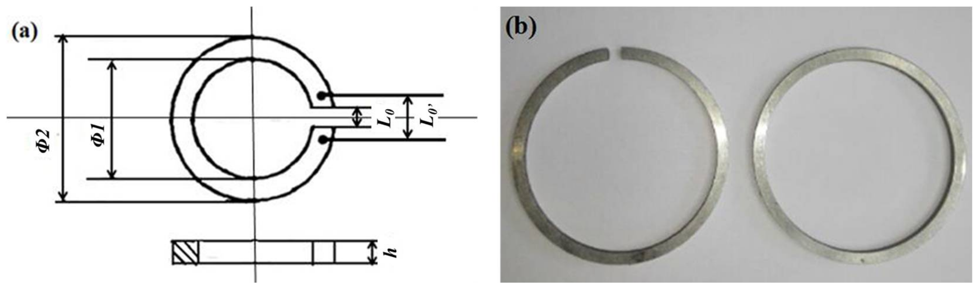
  18. Sun, D.L.; Yang, F.; Wu, G.H. A new method for evaluation of dimensional stability—Open ring method. Phys. Test. Chem. Anal. Part A Phys. Test. 1990, 35, 447–448. [Google Scholar]
  19. Xu, D.K.; Birbilis, N.; Lashansky, D.; Rometsch, P.A.; Muddle, B.C. Effect of solution treatment on the corrosion behavior of the aluminum alloy AA7150: Optimisation for corrosion resistance. Corros. Sci. 2011, 53, 217–225. [Google Scholar] [CrossRef]
  20. Xu, L.Y.; Zhu, J.; Jing, H.Y.; Zhao, L.; Lv, X.Q.; Han, Y.D. Effects of deep cryogenic treatment on the residual stress and mechanical properties of electron-beam-welded Ti–6Al–4V joints. Mater. Sci. Eng. A 2016, 673, 503–510. [Google Scholar] [CrossRef]
  21. Feng, Z.Q.; Yang, Y.Q.; Huang, B.; Han, M.; Luo, X.; Ru, J.G. Precipitation process along dislocations in Al–Cu–Mg alloy during artificial aging. Mater. Sci. Eng. A 2010, 528, 706–714. [Google Scholar] [CrossRef]
  22. Ratchev, P.; Verlinden, B.; Smet, P.D.; Houttea, P.V. Precipitation hardening of anal–4.2 wt. % Mg–0.6 wt. % Cu alloy. Acta Mater. 1998, 46, 3523–3533. [Google Scholar] [CrossRef]
Figure 1. Open ring sample: (a) two-dimensional schematic diagram, (b) ring sample photograph (Φ1 = 50 ± 0.1 mm, Φ2 = 56 ± 0.1 mm, h = ±0.1 mm, L0′ = 5 ± 0.1 mm, L0 = 3 ± 0.1 mm).
Metals 08 00273 g001
Figure 2. Microstructure of 7075 alloy with different cryogenic treatment (CT): (a) 25 °C; (b) 0 °C; (c) −60 °C; (d) −120 °C; (e) −196 °C; (f) −60 °C (twice); and (g) −120 °C (twice).
Metals 08 00273 g002
Figure 3. Energy dispersive spectroscopy (EDS) analysis results of the coarse secondary phase.
Metals 08 00273 g003
Figure 4. TEM image of the fine secondary phase particles in grain experienced after different CT temperatures: (a) 25 °C and (b) −120 °C.
Metals 08 00273 g004
Figure 5. TEM image of precipitates adjacent to the grain boundary of the sample after different CTs: (a) 25 °C and (b) −120 °C.
Metals 08 00273 g005
Figure 6. X-ray diffractometer (XRD) patterns of the 7075 alloys samples with CTs of 25 °C, 0 °C, −60 °C, −120 °C, and −196 °C.
Metals 08 00273 g006
Figure 7. Deformation of sample after quenching process.
Metals 08 00273 g007
Figure 8. Residual stress ratio curves of 7075 alloy after different CT temperatures.
Metals 08 00273 g008
Figure 9. Curve of 7075 aluminum alloy ring sample size changes vs. aging time.
Metals 08 00273 g009
Table 1. Chemical composition of 7075 alloy (wt. %).
ElementsZnMgCuZrFeSiMnCrTiOther TotalAl
Nominal5.7–6.71.9–2.62.0–2.60.08–0.150.150.120.10.040.060.15bal.
In this study6.22.12.20.110.140.130.10.030.050.15bal.
Table 2. Heat treatment process of 7075 aluminum alloy.
SampleSolution TreatmentCryogenic TreatmentAging Treatment
A466 °C × 1 h-107 °C × 6 h + 163 °C × 18 h
B466 °C × 1 h0 °C × 2 h107 °C × 6 h + 163 °C × 18 h
C466 °C × 1 h−60 °C × 2 h107 °C × 6 h + 163 °C × 18 h
D466 °C × 1 h−120 °C × 2 h107 °C × 6 h + 163 °C × 18 h
E466 °C × 1 h−196 °C × 2 h107 °C × 6 h + 163 °C × 18 h
F466 °C × 1 h−60 °C × 2 h,
Twice
107 °C × 6 h + 163 °C × 18 h
G466 °C × 1 h−120 °C × 2 h,
Twice
107 °C × 6 h + 163 °C × 18 h
Table 3. Relative diffraction peak intensity of the samples after CT.
Sample(111)(200)(220)(311)
A57.3710053.6922.2
B78.9110050.3520.3
C19.0410040.4916.2
D22.6810030.845.54
E40.1410054.798.89

