1. Introduction
Hole-flanging belongs to the forming operations and is used when thin-walled structures are produced in order to make material stock for thread. It is the conventional stamping method for pre-producing the hole by forming material onto the cylindrical or coned collar made from standard or high strength steels, using blank holder and hole-flanging punches [
1,
2]. Besides conventional hole-flanging processes with or without wall thinning, new methods appeared, such as incremental forming [
3,
4]. Some limits, such as rapid tool wear and time for tool change, along with maintenance, are connected when conventional methods are used to make the initial hole. Contactless methods, such as drilling via laser-beam with movements along the hole circumference or a direct laser-beam impact to the processed material, appear to be a solution [
5,
6].
Many previous works have investigated the hole-flanging process from different points of view and using different materials. Stachowicz [
7] studied the hole-flanging process on deep drawing steel sheets with a circular hole drilled in the center. He also used punches with different geometries and experimentally determined the effect of both the punch geometry and material mechanical parameters (especially strain hardening and plastic anisotropy) on the expansion limit of the hole. Fracz et al. [
8] studied the thickness distribution when different punch shapes were used. Krichen [
9] determined the effect of the blank-holding on sheet aluminum alloys when constant and progressive forces were applied, as well as when no blank holder was used. Fracz and Krichen also used finite element analysis to research the process and to verify constitutive material models via experimental results. Li [
10] investigated the effect of mechanical properties on the hole flangeability of stainless steel sheets. He found that the flangeability of stainless steel sheets is strongly dependent on both the work hardening exponent and the material anisotropy. Hole-flanging with cold extrusion presented in [
11] avoided necking or fractures during the hole-flanging process, and a substantial flange height and lip thickness could be achieved.
Nowadays, technological processes are investigated via numerical simulations based on a finite elements method. These results show a good agreement between the experimental and simulation results. This resulted from material models developed and implemented in a simulation software and an improvement of experimental measurements’ model constants. Huang [
12] studied the stretch flanging of circular plates via Lagrangian elasto-plastic finite element method. The results of the punch load, deformed geometry and thickness distribution were verified experimentally. Thipprakmas [
13] implemented an FEM (finite elements method) analysis when studying the hole-flanging process for conventional cutting and fine blanking of the initial hole. Thus, they stated better shapes of the flange when fine blanking was used and quantitatively clarified the relationship between the FB-hole-flanging conditions and the flanged shapes. In [
2], the author analyzed process parameters related to the flange forming direction, including punching clearance, flange thickness, and hole expansion ratios. Kacem [
14] predicted the limits of the hole-flanging process through a physically based approach of damage and of verified FEM results via experiments. The results showed that the model accurately predicts all types of failures (orange peel aspect, necking, microvoids, tear) for different conditions and for both materials that were used. Masmoudi [
15] used FEM to analyze the effect of clearance between the die and the punch on the flange height, and they applied a Gurson–Tvergaard–Needleman coupled approach to ensure that the flange was free from fracture. Heng-Sheng [
16] used a numerical simulation to find out the parameters that counter pressure dependent on the inner diameter for hole-flanging with cold extrusion.
The operating variables for tribological contact in metal forming depend on the actual application. One important variable is the normal pressure on the die or punch (usually on the radius), where possible wear can occur. The normal pressure varies from 1 to 100 MPa for sheet metal forming processes, and from 100 to 1000 MPa for drawing with ironing [
17]. Some results investigated by numerical simulation were also presented in [
18] for the deep drawing of automotive parts, as well as in [
19] for the strip drawing test, and in [
20] for the deep drawing. Pereira experimentally revealed the strong relation between high normal pressure zones corresponding to a severe galling wear mechanism [
21].
The wear mechanism in forming processes depends on solid body materials (involving coatings), their relative motion and lubricants. The problem was investigated by Gorscak [
22] for uncoated steel when PVD coatings were applied to the tool. Groche [
23] performed an investigation on different process parameters on the wear of forming tools when zinc-coated sheet metals are processed. He found that the process parameters corresponding to gliding speed and normal pressure influenced the wear of forming tools. Moravec [
24] showed a positive effect of TiCN coating when applied to the cold molding tools. Clarysse et al. [
25] studied the resistance to galling and the abrasive wear for selected coatings by means of a flat/cylindrical multifrottement test and cup test. Silva et al. [
26] improved the wear resistance of a mold by applying a multilayer nanostructured coating: the lifespan was 65.5 times greater than that of the uncoated substrate. Li [
27] studied microstructural, residual stress corrosion and wear resistance for multilayer titanium coatings when deposited on a magnesium alloy.
The surface preparation and droplet elimination after the coating process are important issues for reaching a good tool/coating performance. In the paper [
28], a final elimination of droplets by drag grinding was performed and a positive effect was found for some coatings. In [
29], microblasting mechanical substrate pre-treatments were analyzed with regard to the performance of coated tools. A drag grinding pre-treatment led to an improvement of the coating adhesion and to a reduction of wear at the thread tapping process described in [
30]. Additionally, indirect methods for seeking common features among the group of cutting tools with the best performances on machining have been presented in [
31].
The problem researched in our paper arose when hole-flanging was designed and used in the production of a flange for a self-tapped screw in a structural part of the trailer. The aim of the article is to study the surface condition and wear on the hole-flanging punch when it is made of hardened tool steel without and with PVD coating. In addition, the normal pressure on the punch active surface was studied via a numerical simulation of the hole-flanging process. We suppose that the PVD coating improves the tool life, thus shortening the maintenance time.
2. Materials and Methods
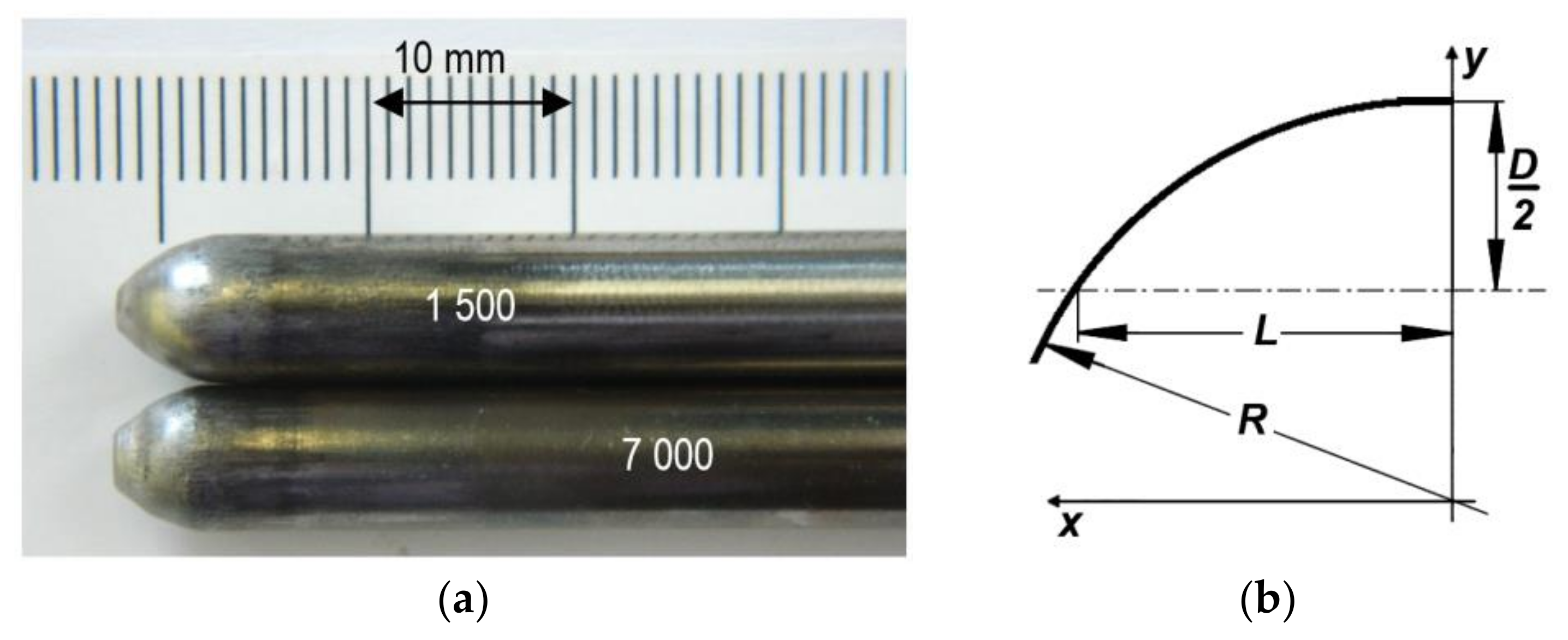
The experiments focused on the hole-flanging process of structural steel S355J2 + N (1.0577) with a thickness of 3 mm. The geometry of the punch and die is shown in
Figure 1. The initial Ø3 mm hole is cut by a CO
2 TruLaser 3040 laser (Trumpf, Ditzingen, Germany) with the following parameters: Power at 3 kW; switching frequency at 2000 Hz; speed at 4.5 m·min
−1; offset at 0.7 mm; gas and gas pressure at O
2/0.6 bar; and corner cooling time of 0.5 s.
The chemical composition of the steel is shown in
Table 1. The mechanical properties are shown in
Table 2.
The punch was made of tool steel 1.3343, heat treated via vacuum hardening and tempered to 61 HRC. The punch surface was machined by grinding and polished to a final roughness of Ra 0.2 µm. The surface topography was inspected with the raster electron microscope JEOL JSM-7000F. The chemical composition of the tool steel is shown in
Table 3.
PVD coating TiCN-MP was deposited via LARC (Lateral Rotating Arc-Cathode) technology. The main process parameters were as follows: Bias 160 V, ARC Ti-180 A, pressure 0.008 mbar, temperature 430 °C. The chemical composition of the coating was measured via Glow Discharge Optical Emission Spectroscopy (GD-OES, Leco Instrument, Joseph, MI, USA) as deep level concentration profiles. The phase composition of the coating was examined via a grazing incidence X-ray diffraction method (Bruker AXS GmbH, Karlsruhe, Germany). All records of the qualitative phase analysis were measured with an impact angle of 2°, within an interval of 20° to 100°.
The Calotest method was used to measure the coating thickness. The indentation microhardness was measured via tester TTX-NHT S/N (Anton Paar GmbH, Graz, Austria) with a diamond indenter Berkovich at a maximal load of 60 mN and a sinus mode (frequency 15 Hz, amplitude 6 mN and holding time at max. load 10 s).
The surface topography was measured via an optical method of confocal microsopy and optical interferometry, with a phase shift interference (PSI) regime, a vertical resolution of PSI <0.02 nm and a control length 636 µm. The surface topography was also verified via the electron microscope JEOL JSM-7000F (JEOL Ltd., Tokyo, Japan) and Vega3 Tescan microscope (TESCAN Brno, s.r.o., Brno, Czech Republic). Scanning electron microscopy (SEM) analyses were done using a secondary electron (SEI) regime, with a bias of 10 kV and a work distance of 10 ± 2 mm from the sample surface.
The adhesion of TiCN-MP coating to the hardened tool steel was identified via a Micro-Scratch test with a linear increase of the normal force Fz to −120 N. The test was done using the device UMT/APEX Multi-Specimen (Bruker, Campbell, CA, USA) with a diamond Rockwel indentor and a sample speed of 0.01 mm·s−1. The adhesion properties of the coating system were evaluated from the view of the scratch line morphology, fracture of the coating on the scratch line-coating edge, as well as from the graphic records of the acoustic emission AE and the friction coefficient COF, both depending on a normal force Fz.
The friction coefficient of the coating was measured via a Pin-On-Disc test on the tribometer CSM HT device (CSM Instruments, Needham, MA, USA). During the test, a hardened Ø6 mm steel ball was used, and loads of 2, 4 and 5 N were applied. The speed was 20 cm·s−1 and sliding distance 200 m.
A numerical simulation of the hole-flanging process was done in the software Pam Stamp 2G, commonly used when forming processes are simulated. A surface CAD model was created according to the punch and die dimensions (
Figure 1). Following this, it was imported and meshed via a DeltaMesh module with the size of the elements between 0.1 and 30. These parts were defined as a Rigid Body; no elastic deformation was therefore allowed.
The model of the processed material was constituted via a Hill 48 yield condition and Krupkowsky strain hardening equation. The values of the constant were calculated from the results of the tensile test via ISO 6892-1, as shown in
Table 2. Due to material thickness, the volume blank was defined and meshed in thickness onto 5 layers with an element size of 0.35 mm. Thus, hexahedron volume elements were created.
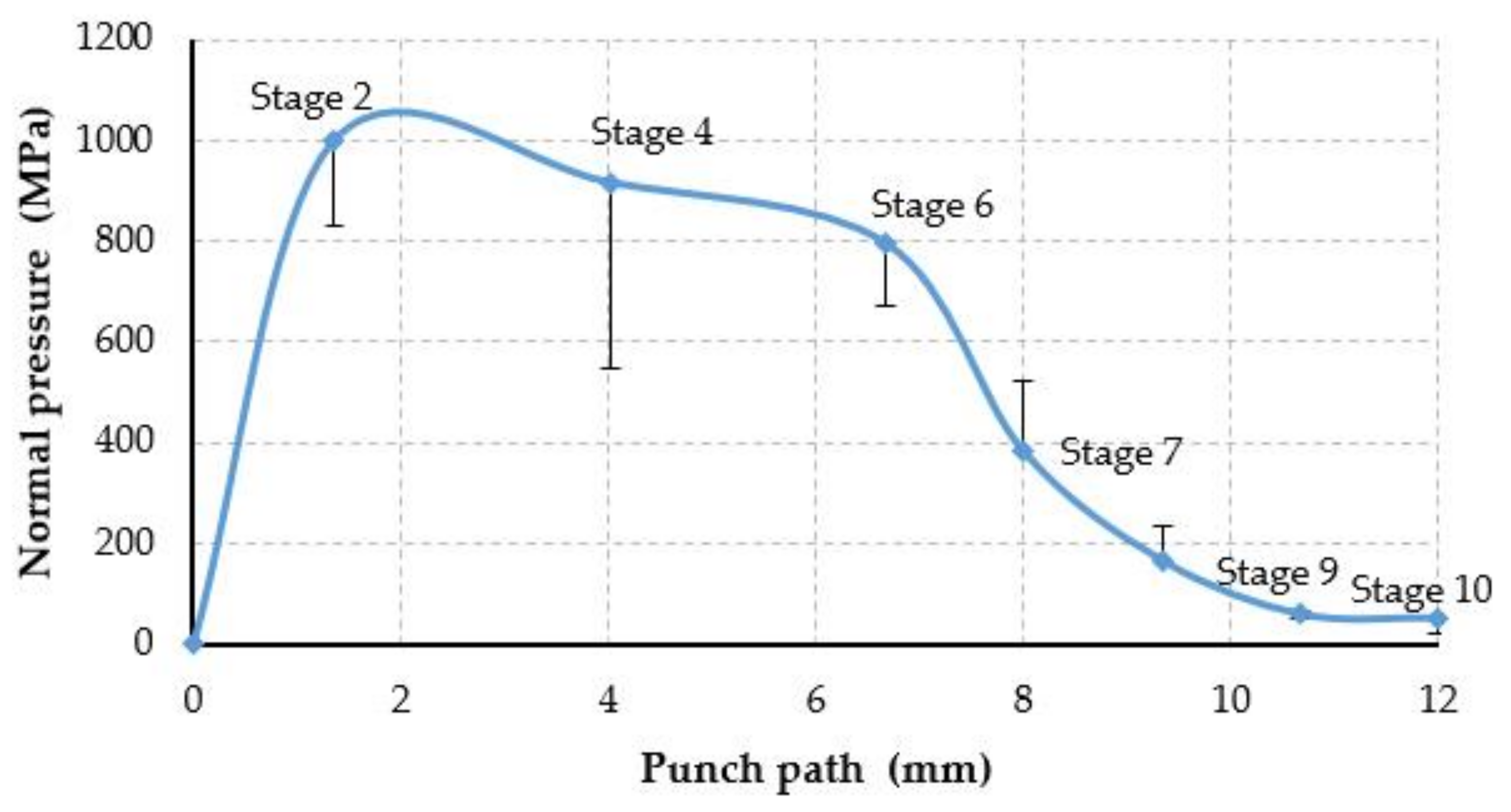
A Coulomb friction condition was set with a friction coefficient ranging from 0.3 (the value specified by the software manual) to the maximal values measured on the Pin-On-Disc test. The contact pressure on the punch surface was evaluated in 10 states during the punch path in order to identify the maximal contact pressure.


