Modeling and Experimental Study of Ore-Carbon Briquette Reduction under CO–CO2 Atmosphere


State Key Laboratory of Advanced Metallurgy, University of Science and Technology Beijing, Beijing 100083, China
*
Author to whom correspondence should be addressed.
Metals 2018, 8(4), 205; https://doi.org/10.3390/met8040205
Submission received: 26 February 2018
/
Revised: 14 March 2018
/
Accepted: 21 March 2018
/
Published: 23 March 2018
(This article belongs to the Special Issue Ironmaking and Steelmaking)
Abstract
:Iron ore-carbon briquette is often used as the feed material in the production of sponge iron via coal-based direct reduction processes. In this article, an experimental and simulation study on the reduction behavior of a briquette that is made by hematite and devolatilized biochar fines under CO–CO2 atmosphere was carried out. The reaction model was validated against the corresponding experimental measurements and observations. Modeling predictions and experimental results indicated that the CO–CO2 atmosphere significantly influences the final reduction degree of the briquette. Increasing the reduction temperature did not increase the final reduction degree but was shown to increase the carbon that was consumed by the oxidative atmosphere. The influence of the CO–CO2 atmosphere on the briquette reduction behavior was found to be insignificant in the early stage but became considerable in the later stage; near the time of the briquette reaching its maximum reduction degree, both iron oxide reduction and metallic iron re-oxidation were able to occur.
1. Introduction
An ore-carbon briquette is a composite briquette consisting of iron-bearing oxide and carbonaceous materials that were used as feed material in some coal-based direct reduction processes, such as FASTMET® (FASTMET is a trade mark of MIDREX Co., USA.) and ITMK3® (ITMK3 is a trademark of KOBE Steel Co., Japan.) [1,2,3,4]. The use of these briquettes offers advantages, such as a high reduction rate, utilization of non-coking coal, and biochar for producing sponge iron economically. The ore-carbon briquette reduction technology is often used in treating various metallurgical dust and sludge [5,6,7], recovering valuable metals, such as nickel and titanium, from complicated minerals [8,9,10,11], and upgrading refractory iron ores by removing detrimental minerals, such as quartz and alumina [12,13,14]. The reduction of ore-carbon briquettes is usually carried out at the industrial level using rotary hearth furnace (RHF) reduction technology [15]. In an RHF process, the briquette is fed onto the rotating hearth of the RHF and is reduced into sponge iron in a high-temperature environment. The flue gas from the combustion of coal gas, composed of CO, CO2, H2, and H2O, forms a weakly oxidative atmosphere on the surface of the briquette [16,17,18]. The CO2 or H2O levels may allow for the metallic iron oxidation of the ore-carbon briquette during the RHF process, which would have a negative effect on the quality of the products. Therefore, studies are required to address the reduction behavior of ore-carbon briquettes under the RHF reactive atmosphere.
The reaction kinetics of iron ore-carbon briquettes under inert atmosphere (nitrogen or argon) have been extensively studied, and their major features are well established [19,20,21,22]. The reduction of the briquette proceeds rapidly under high temperatures and generates a large amount of gas inside the briquette, making it more complicated than the reaction behavior of an iron ore or coal briquette. The reaction kinetics depend significantly on the chemical composition and physical properties of the briquette. Some studies on ore-carbon reduction have been conducted under the oxidative atmosphere by Singh et al. [23] and by Ghosh et al. [24], but such studies are scarce. There are several mathematical descriptions of the reduction phenomenon of the iron ore-carbon briquette. For example, Moon et al. [25] developed a model with an assumption of uniform conversion of iron oxide and carbon particles in the briquette, Sun and Lu [26] and Shi et al. [27] developed models including the expressions of chemical kinetics, equations of mass transfer, and equations of heat transfer, and Donskoi et al. [28] developed a model when considering the swelling/shrinkage of the briquette. Although these models attempt to give a comprehensive understanding of the reduction behavior of the briquette, the interaction between the briquette and the oxidative atmosphere has not been included. Therefore, the effect of the oxidative atmosphere on the reduction behavior of ore-carbon briquette has been overlooked in the existing studies.
The first aim of this study was to conduct kinetic experiments of the isothermal reduction behavior of the ore-carbon briquette under a simulated RHF atmosphere (CO–CO2 atmosphere with PCO/PCO2 = 1.0). The second aim was to establish and develop a reaction model of ore-carbon briquette reduction that includes the reaction of metallic iron with CO2. The simulation results were compared to the experimental results in respect to briquette mass change, briquette carbon conversion, briquette reduction degree, and briquette reduction progress. The reduction behavior of the briquette under the CO–CO2 atmosphere was also analyzed.
2. Experiments
2.1. Materials and Briquette Preparation
The iron ore sample was from Tangshan Iron and Steel Company (Tangshan), China. The carbonaceous reductant sample was prepared by carbonizing the biochar under 1273 K for 1 h. The chemical composition of the employed biochar is given in [29]. Chemical composition of the ore sample is listed in Table 1. Fe2O3 content in Table 1 was analyzed by chemical analysis (iron chloride method) and contents of other components in Table 1 were examined by energy-dispersive X-ray fluorescence spectrometry (XRF) using an XRF 1800 spectrometer (Shimadzu Co., Kyoto, Japan), and the proximate analysis of the carbonaceous reductant sample is listed in Table 2. Both of the samples were ground using a F-P400 ball mill (Focucy Co., Changsha, China), and the average sizes of the ore fines and reductant fines were 100 and 80 µm, respectively. The mixture was thoroughly mixed with an addition of 2% cellulose binder (Dingshengxin Co., Tianjin, China), 5% reagent-grade CaO powder (Xilong Co., Shantou, China), and 10% distilled water. Molar ratio of fixed carbon in the reductant fines to oxygen in the iron oxide of the ore fines was 1.0. The moistened fines were pressed with a die under a pressure of 40 MPa to make the briquettes. The briquettes were then air-dried for 24 h, followed by drying at 473 K for 2 h. The prepared briquettes had a cylindrical shape with a diameter (D) of 20 mm, a height (H) of 10 mm, and a mass of approximately 6.0 g.
2.2. Experimental Setup and Procedures
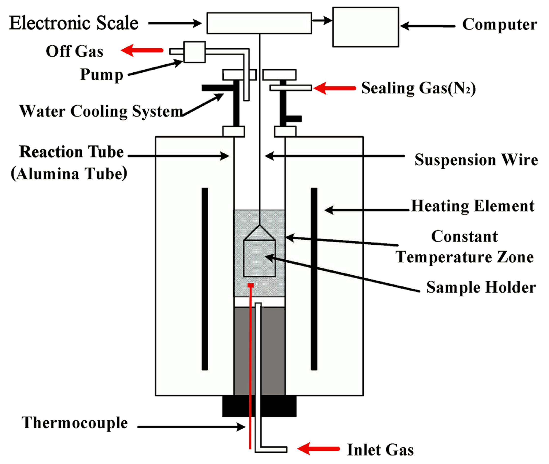
The experimental device, schematically presented in Figure 1, includes a gas supply system, an electronic scale with an accuracy of ±0.001 g, and a temperature-controlled furnace with an accuracy of ±2 K. The furnace was heated by MoSi2 elements, producing a 50 mm hot zone in the reaction tube, with an inner diameter of 60 mm. The sample holder was made of a heat-resistant alloy wire (Fe–Cr–Al).
The furnace was preheated to the desired temperature under N2. One briquette was then loaded into the sample holder, preheated at 773 K for 5 min in the upper part of the reaction tube, and then introduced into the hot zone. At this time, the N2 feed was replaced with a CO–CO2 gas mixture, PCO/PCO2 = 1.0, and the mass loss/gain of the briquette was measured by an electronic scale and was recorded by a computer at an interval of 2 s. After the predetermined time, the briquette was withdrawn from the reaction tube and quenched by a N2 stream. In all of the individual tests, a constant gas flow rate of 1600 cm3/min (Standard Temperature and Pressure) at the gas inlet was maintained. In addition, some reduced briquettes were subjected to carbon content analysis, scanning electron microscopy (SEM), and energy dispersive spectrometry (EDS) examinations. The carbon analysis was conducted using a CS-2800 infrared carbon sulfur analyzer (NCS, Beijing, China); SEM and EDS were performed using a Quanta-250 scanning electron microscope (FEI, Hillsboro, OR, USA). The definitions and calculation methods of mass-loss fraction (), reduction degree () and carbon conversion () of the tested briquette are , , and , respectively [30], where, , , and are the mass loss, carbon mass loss, and oxygen mass loss of the briquette at time t, respectively; , , and are the initial mass, initial carbon mass, and initial iron-oxide oxygen mass of the preheated briquette, respectively; and is the carbon content of the sample at time t. , , and are available, according to the preparation procedure of the briquette.
3. Mathematical Model
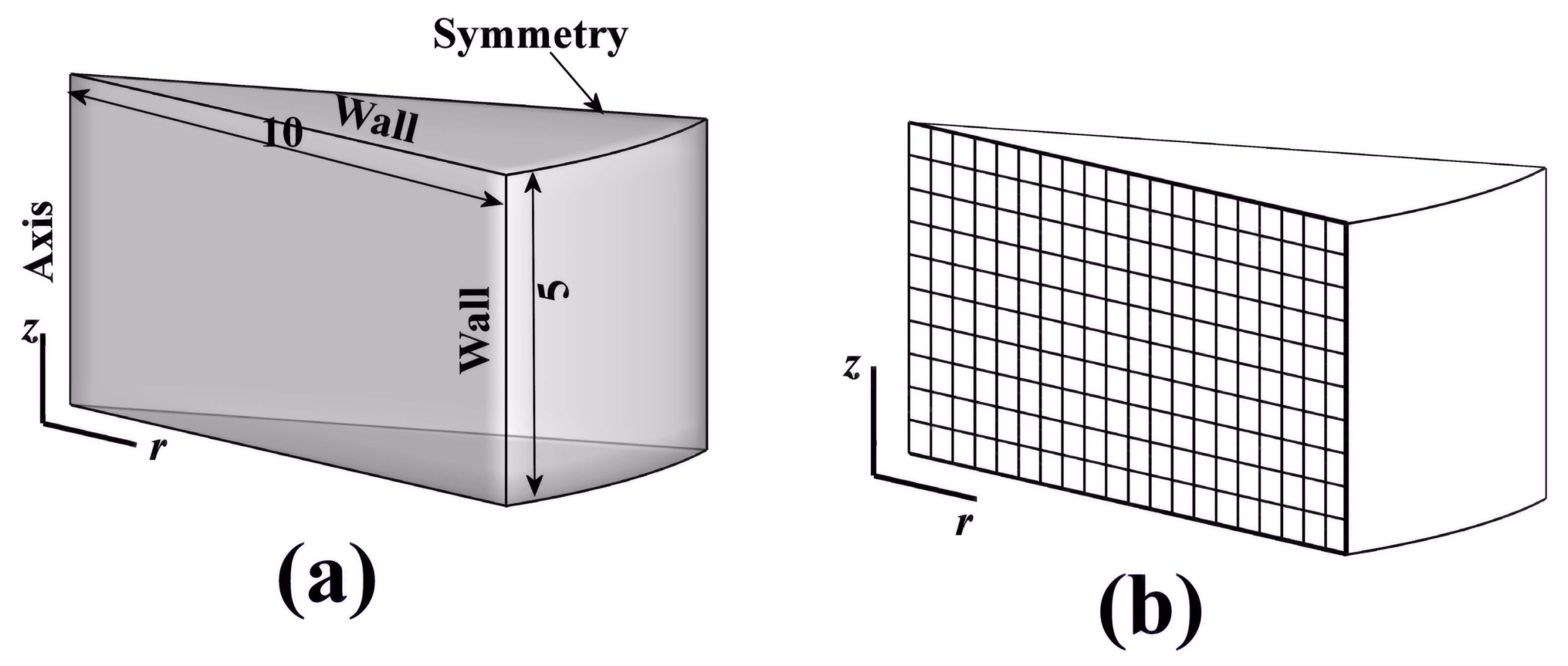
A mathematical model was established for the reduction process on a single cylindrical briquette. According to the symmetry of the geometry and the experimental conditions, a simplified geometrical model is shown in Figure 2a. The computational domain was chosen as 0.5 radian, and three types of boundary conditions, including wall, symmetry, and axis, were used in the simulations. Figure 2b schematically shows the structure’s grid system, which used a grid of 40 × 20.
Several assumptions were made during model development to express the behavior of a briquette. Briquette reduction was considered under isothermal conditions, swelling/shrinking of the briquette was not considered, and the porosity of the briquette was assumed to be constant. Similar assumptions can be found in many studies [7,25,26,27] involving the modeling of the reduction of the ore-carbon briquette, and therefore it is considered that these assumptions would not cause considerable errors.
The overall reduction process is believed to occur through an intermediate gas phase. The reactions that take place in the briquette are the stage-wise reductions of iron oxide by CO (Equations (1)–(3)), the Boudouard reaction of carbon particles (Equation (4)), and metallic iron oxidation (Equation (5)). The reduction of iron oxide by solid carbon may also occur; however, it is difficult to estimate the extent of this reaction, and the share of the solid-state reduction is minimal when considering the much larger gas–solid contact area. Therefore, no solid–solid reaction was taken into account.
The gas phase in the briquette was considered to be ideal and to consist of CO and CO2. Dependencies of the gas properties on local temperature and composition were calculated according to the ideal gas law in the FLUNET material database [31].
Gas transfer in the reduction of an ore-carbon briquette is driven by two factors: the concentration gradient and the pressure gradient. Gas transfer by pressure gradient is negligible in most cases; therefore, the total gas pressure on the computational domain was fixed at atmospheric pressure, and it is shown below in Equation (6).
The equation of species CO2 on the computational domain was then given by Equation (7) using the effective coefficient with Fick’s law:
where . The equation of species CO is shown below in Equation (8).
Deff in Equation (7) depends on the porous structure of the briquette, and it was determined using the Weisz–Schwartz relationship, given by Equation (9) [32].
Equations (6)–(8) formed the governing equations of the gas phase. The boundary and initial conditions for Equation (7) were given by Equations (10)–(13). Under experimental conditions, the velocity and other gas properties of the furnace atmosphere in Equations (10) and (11) were considered as equal to their respective values at the gas inlet of the furnace. Additionally, the equivalent diameter of the cylindrical briquette was assumed as the overall diameter.
where [33].
The governing equations used for the solid phase are given below as Equations (14)–(18).
The initial conditions for Equations (15)–(18) are , , , , , and, .
4. Solution Method
The FLUENT CFD package (v6.3, Fluent Inc., Lebanon, NH, USA) [31] was used for conducting the numerical simulations. Equation (7) was spatially and temporally discretized using a fully implicit first-order upwind scheme. The time step was 0.01 s, the under-relaxation factor was 0.1, and the convergence criterion used was 1.0 × 10⁻⁵. An explicit time integration method was adopted for solid-phase equations.
5. Results and Discussion
5.1. Determination of Model Parameters and Reaction Rates of Invovled Reactions
Before performing simulations, some parameters and rate expressions of the involved reactions must be determined. Lu and Sun [21] reported that variation of the briquette porosity varied from 0.40 to 0.68 in the reduction process of the ore-carbon briquette, and the porosity of the briquette was thus assumed to be α = 0.50 in the present study.
Gaseous reduction of iron ore particles has been extensively studied in its thermodynamics and kinetics. Generally, shrink unreacted core model is consistent with the step-wise of iron oxides. As the hematite particles are very small, the reactions that are given by Equations (1)–(3) were considered to proceed independently [34]. Their reduction rates were thus described using a one-interface unreacted shrinking core model, as Equation (19).
where , , and for R1; , and for R2; and, , , and for R3 [35]. Definition of fi in Equation (19) is given in [32]. The internal gas diffusion resistance of R1 was not considered because the transformation of Fe2O3 to Fe3O4 (Equation (1)) proceeds very quickly in the initial stage of the briquette reduction.
The rate of the reaction given in Equation (5) is Equation (21) [37].
where , and .
In estimating NP in Equations (19)–(21), the true density of the hematite particles was assumed to be 5000 kg/m3. γ in Equations (19)–(21) is a coefficient for adjusting the specific area of ore particles due to their irregular geometry, and it was determined to be 0.4 by a trial-and-error method.
5.2. Briquette Mass Change
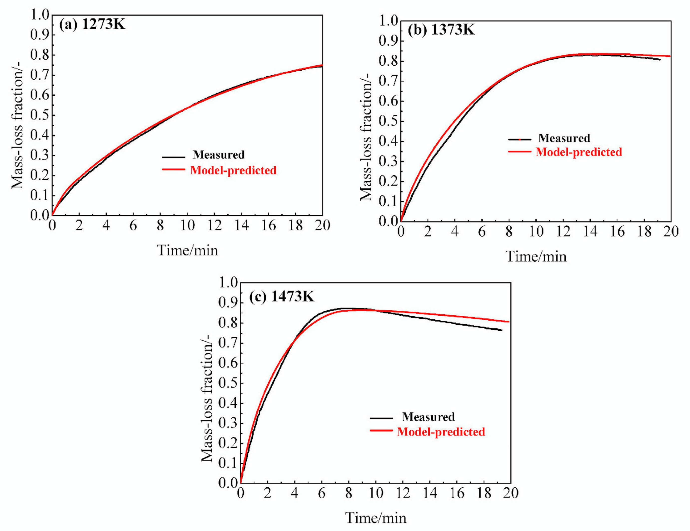
Mass change in the briquette during reduction was caused by several reactions; the reactions given by Equations (1)–(4) led to a decrease in mass, whereas the reaction given by Equation (5) led to an increase in mass. Measured and model-predicted mass-loss fraction curves under different temperatures were compared, and the results are shown in Figure 3. In simulations, the briquette mass-loss fraction at time t was calculated using Equation (22).
The model predictions closely match the experimental measurements at 1273 K and 1373 K, as can be seen in Figure 3a,b; however, under 1473 K, some deviation occurs in the later reduction stage (Figure 3c). In view of the assumptions that are made in the model and errors in the measurements, the agreement between them is considered to be satisfying.
The shape of all of the mass-loss fraction curves presents some common features. The briquette reduction can be divided into three fairly distinguishable stages. The first stage comprises the mass loss, the second stage corresponds to the mass loss reaching its maximum value, and the third stage includes the mass increase. The mass loss/gain characteristics became more evident with an increasing temperature.
5.3. Briquette Reduction Degree and Briquette Carbon Conversion
Because the mass change of the briquette is affected by several reactions, it cannot adequately reflect the briquette reduction behavior. However, the briquette reduction degree and carbon conversion are important parameters for evaluating the quality of the reduced briquette. In the simulations, the briquette reduction degree at time t was calculated using Equation (23), and the briquette carbon conversion at time t using Equation (24).
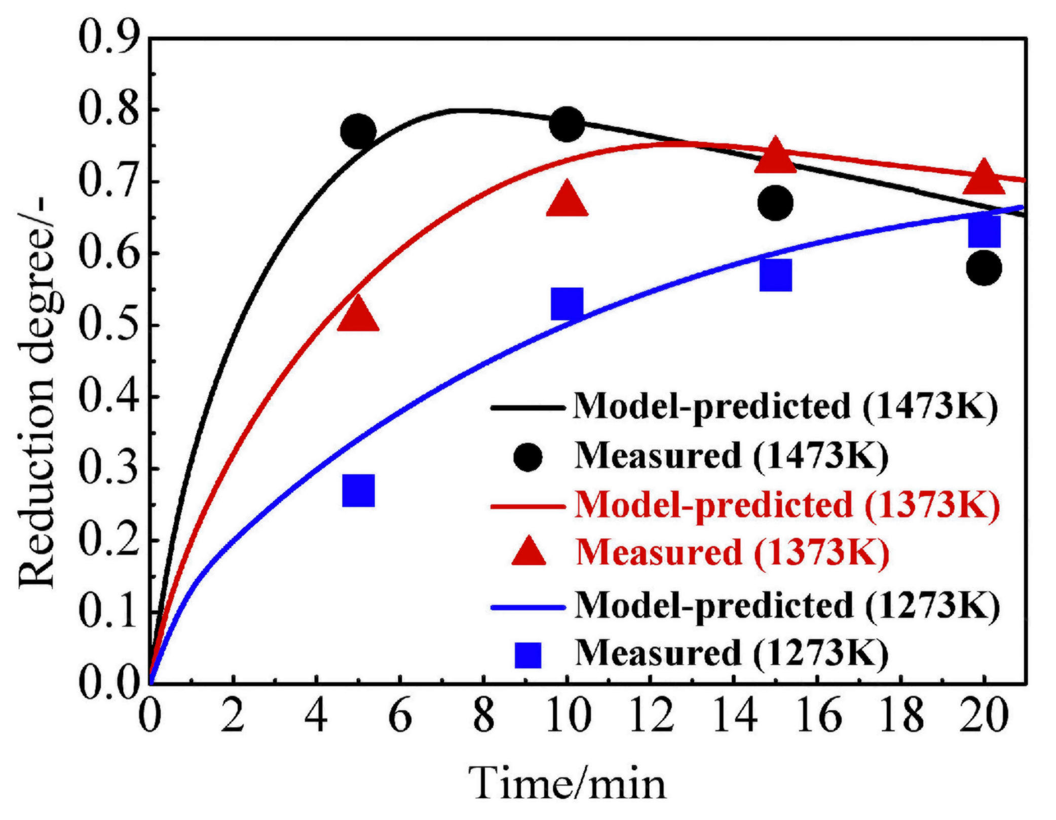
The model-predicted and measured briquette reduction degrees under three temperatures are shown in Figure 4. The average difference in reduction degree between model predictions and experimental measurements was less than 0.03; therefore, it can be concluded that the developed model is applicable to the reduction of the ore-carbon briquette. Model predictions at 1273 K present a successive increase of reduction degree throughout the reduction period. At 1373 K, the reduction degree increased in the early stage and reached its maximum reduction degree of 0.75 at approximately 12 min; thereafter, it decreased. Briquette reduction behavior under 1473 K was similar to that under 1373 K, except that it reached a maximum reduction degree of 0.80 at approximately 6 min. After 15 min, the reduction degrees of the briquette under 1473 K and under 1373 K are quite close, and by 20 min, the reduction degrees under the three temperatures are nearly the same. These findings indicate that, under the oxidative atmosphere, increasing the temperature does not increase the final reduction degree of the briquette.
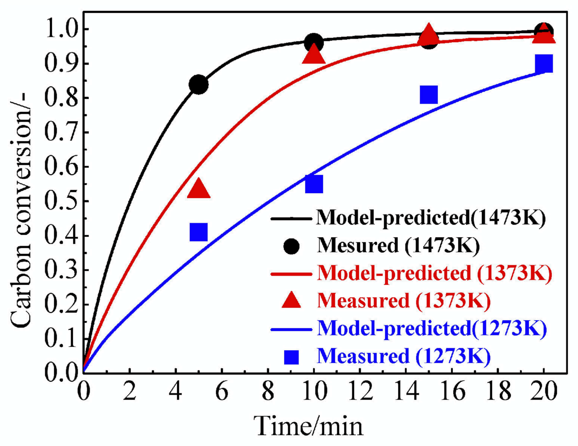
The model-predicted briquette carbon conversion is compared to the corresponding experimental measurements in Figure 5. The briquette carbon conversion increased with time at all three temperatures. Model-predicted curves at 1373 K and 1473 K show that, after reaching their maximum reduction degree (at 12 min under 1373 K and at 7 min under 1473 K), the carbon conversion increased much more slowly. By 20 min, the final carbon conversion was lower at 1273 K than at 1373 K and 1473 K. Combing the results from Figure 4 and Figure 5 indicates that more biochar could be consumed by the atmosphere with the increase of the temperature.
5.4. Briquette Reduction Progress
Briquette reduction under 1473 K was selected for further study of the briquette reduction progress because it displayed the major characteristics of hematite-biochar reduction under the oxidative atmosphere: fast reduction in the early stage and obvious metallic iron oxidation in the later stage.
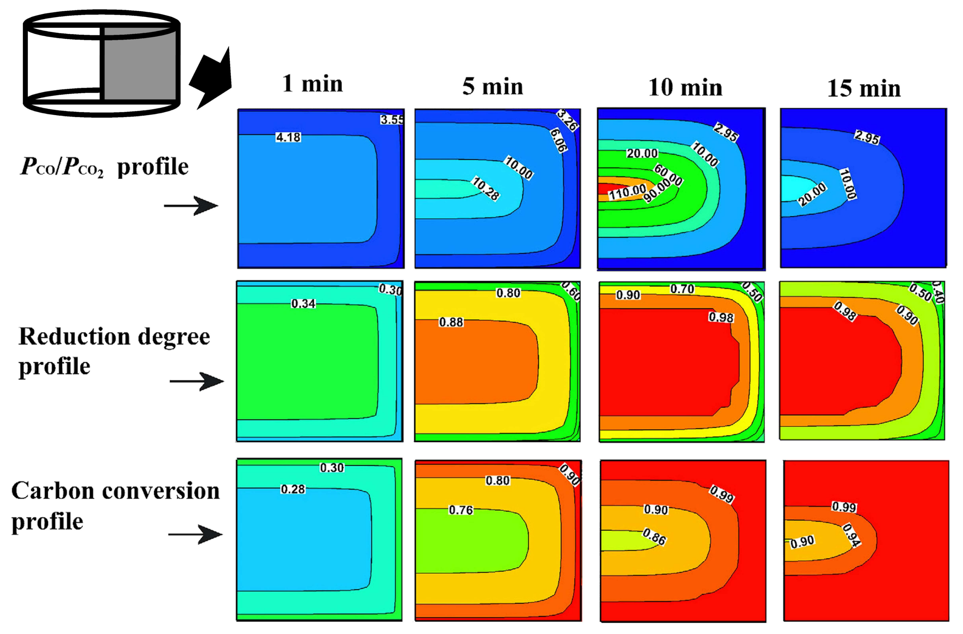
The simulation results of the development of local PCO/PCO2, the local reduction degree profile, and the local carbon conversion profile on the briquette cross section are displayed in Figure 6. In Figure 6, the local reduction degree and carbon conversion at time t were calculated by and , respectively. These simulation results were then used to assume the reduction progress of the briquette. At the beginning stage, the dominant reactions were assumed as the reactions that are given by Equations (1), (2) and (4). Owing to the intense gas generation, the briquette reduction progress was assumed to not be influenced by the atmosphere or gas diffusion. At 1 min, PCO/PCO2 was nearly uniformly profiled at a level of approximately 4.0; both the reduction degree and the carbon conversion profiles were uniform and at a degree of approximately 0.3. As time proceeded, the reactions that were given by Equations (3) and (4) became dominant. As the rate of generated product gas was reduced, the effect of gas diffusion increased. At 5 min, the atmosphere began to influence the briquette reduction progress, and the PCO/PCO2 profile in the briquette became uneven: at the core, it increased to 10.28, whereas at the surface, it only increased to 3.26. Correspondingly, the reduction degree increased to 0.88 at the core and to 0.60 at the surface, and carbon conversion increased to 0.76 at the core and to 0.90 at the surface. By 10 min, PCO/PCO2 remained higher than 2.95 in the internal part of the briquette (K5 = 2.95 under 1473 K), and reached 110 at the core, so that the reaction given by Equation (3) could still proceed there. However, PCO/PCO2 decreased to less than 2.95 at the surface of the briquette, and consequently, the reaction that was given by Equation (5) took place and became a dominant reaction. At 10 min, reduction degree increased in the internal area and reached 0.98 at the core; at the surface, it decreased to 0.50. By the end of the reduction, the dominant reactions changed to those given by Equations (4) and (5). The contour line of PCO/PCO2 = 2.95 became closer to the core, and PCO/PCO2 at the core decreased to 20.0, which reflected that the atmosphere was extending its influence toward the core. At 15 min, the reaction that was given by Equation (3) ceased. In the region with PCO/PCO2 > 2.95, the reduction degree remained higher than 0.90. However, the reaction given by Equation (5) became significant as the region with PCO/PCO2 < 2.95 was enlarged. The reduction degree at the surface further decreased to 0.40, and the weak gasification of the remaining carbon particles was then attributed to CO2 from the atmosphere.
Thus, the reduction of the briquette presented a mainly homogeneous reaction system in the period from 1 to 5 min, whereas the gas transfer and the oxidative atmosphere became considerable after 5 min. Both metallic re-oxidation and iron oxide reduction appeared as the briquette neared its maximum reduction degree.
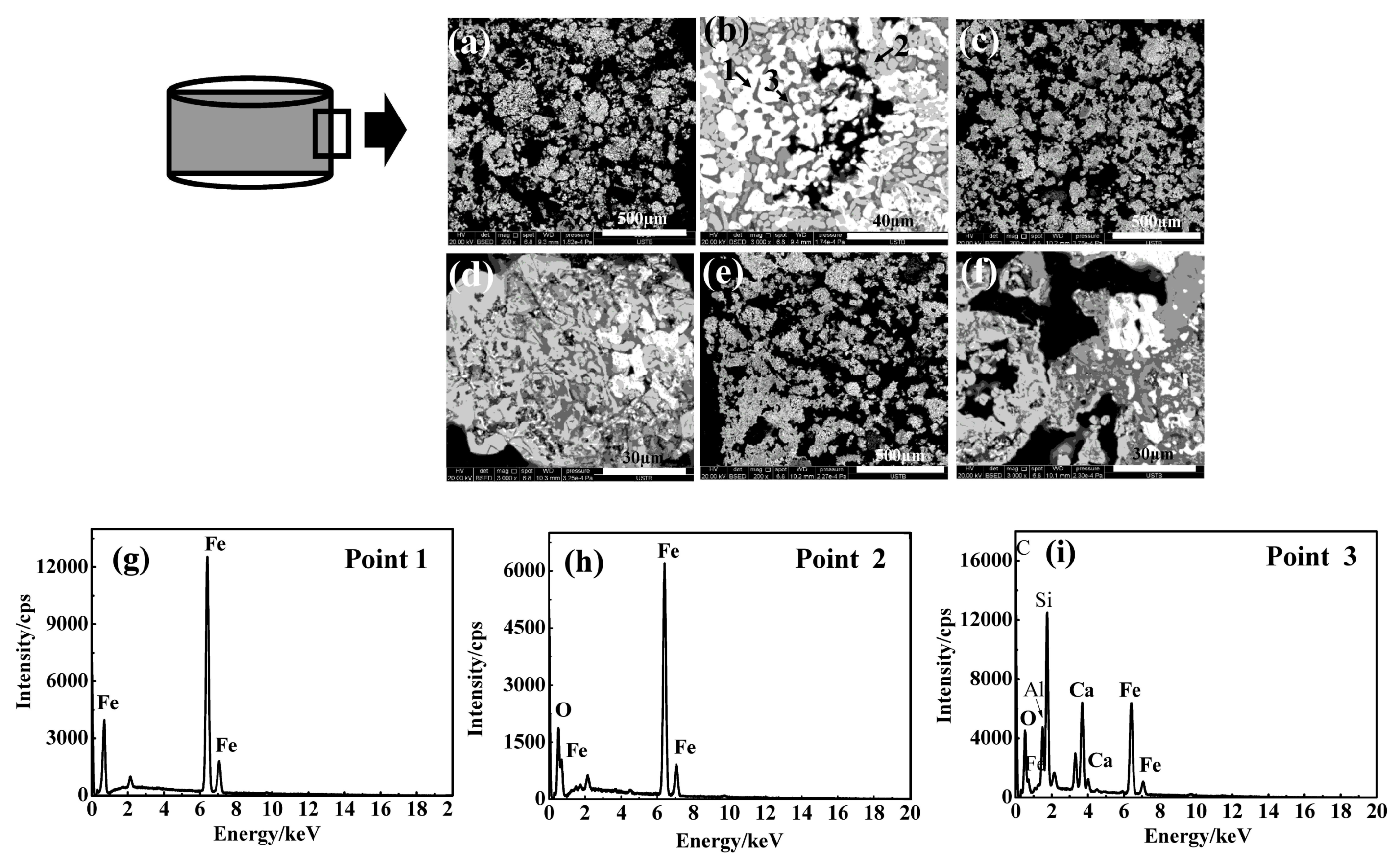
SEM–EDS results on intermittent morphologies at the briquette side surface in the reduction course at 1473 K are shown in Figure 7. The ore particles were uniformly distributed at 5 min (Figure 7a), and a mixture of tiny metallic iron grains (Point 1 in Figure 7b), wustite grains (Point 2 in Figure 7b), and gangue grains (Point 3 in Figure 7b) was presented within ore particles (Figure 7b). The deformation and the sintering of ore particles had occurred by 10 min (Figure 7c), and iron grains became scarce in the particles (Figure 7d). The decrease of iron grains was due to the re-oxidation by the atmosphere, and the ore particle sintering and deforming were attributed to wustite reacting with gangue components (CaO, SiO2, and Al2O3) to form low-melting-point compounds (glass phase). By 15 min, the sintering degree of ore particles had increased (Figure 7e), and the size of some remaining iron grains in ore particles was enlarged (Figure 7f). Iron grain growth was attributed to an agglomeration of tiny iron grains that was facilitated by the glass phase. Overall, the SEM–EDS results indicate that the briquette side surface underwent oxidation after 5 min in the reduction course, which was in accordance with the simulated reduction process. The intense self-reduction in the early reduction stages lead to crack generation at the briquette surface so that iron oxidation near the surface was accelerated in the later stage as the porosity near the surface was increased. Therefore, crack formation near the surface could be the main reason for the deviation between model predictions and the experimental measurements in the later stage of reduction, as shown in Figure 3c.
6. Conclusions
- A model to predict the reduction behavior of the ore-carbon briquette under CO–CO2 atmosphere was developed. The model included the kinetics of the stage-wise reduction of iron oxide, carbon gasification and metallic iron oxidation, and it was with the assumptions of constant porosity and size of the briquette. The simulation results were validated by the experimental measurements and observations and the model was found to be reliable.
- The CO–CO2 atmosphere can significantly influence the final reduction degree of the briquette, and the briquette cannot reach higher final reduction degree by further increasing the temperature. Under higher temperatures, more carbon is consumed by the reactive atmosphere.
- In the briquette reduction progress, the briquette reduction behavior is not initially influenced by the CO–CO2 atmosphere; however, near the maximum reduction degree, both iron oxide reduction and metallic iron re-oxidation can occur in the briquette.
Acknowledgments
The authors thank the National Natural Science Foundation of China (No. 51144010), and the State Key Laboratory of Advance Metallurgy USTB for the financial support of this work.
Author Contributions
Huiqing Tang conceived and designed the experiments; Zhiwei Yun and Xiufeng Fu performed the experiments; Zhiwei Yun and Xiufeng Fu analyzed the data; Shen Du contributed reagents/materials/analysis tools; Huiqing Tang wrote the paper.
Conflicts of Interest
The authors declare no conflict of interest.
Abbreviations
| Table of Symbols | |
| dore | diameter of ore particle, (m) |
| De,i | interior diffusion coefficient of the reaction given by Equation (i), (m·s−1) |
| DCO–CO2, Deff | gas diffusivity, effective gas diffusivity, (m2·s−1) |
| fi | reaction fraction of the reaction given by Equation (i) |
| ki | reaction rate constant of the reaction given by Equation (i), (unit vary) |
| kg | external mass transfer coefficient, (m·s−1) |
| Ki | equilibrium constant of the reaction given by Equation (i) |
| M | molar weight, (kg·mol−1) |
| NP | number density, (m−3) |
| Re | Reynolds number |
| R | gas constant, (8.314 J·mol−1·K−1) |
| Ri | reaction rate of the reaction given by Equation (i), (kg·m−3·s−1) |
| Sc | Schemidt number |
| T | temperature, (K) |
| Vcell | cell volume, (m3) |
| t | time, (s) |
| y | mass fraction |
| α | porosity |
| ρ | local density, (kg·m−3) |
| Subscriptions | |
| 0 | initial |
| g | gas |
| f | furnace |
| Species or element name | variable of assigned species or element |
References
- Ahmed, H.M.; Viswanathan, N.; Bjorkman, B. Composite pellets—A potential raw material for iron-making. Steel Res. Int. 2014, 85, 293–306. [Google Scholar] [CrossRef]
- Nikai, I.; Garbers-Craig, A.M. Use of iron ore fines in cold-bonded self-reducing composite pellets. Miner. Process. Extr. Metall. Rev. 2016, 37, 42–48. [Google Scholar] [CrossRef]
- Chukwuleke, O.P.; Cai, J.J.; Chukwujekwu, S.; Song, X. Shift from coke to coal using direct reduction method and challenges. J. Iron Steel Res. Int. 2009, 16, 1–5. [Google Scholar] [CrossRef]
- Manning, C.P.; Fruehan, R.J. Emerging technologies for iron and steelmaking. JOM 2001, 53, 36–39. [Google Scholar] [CrossRef]
- Mae, K.; Inaba, A.; Hanaki, K. Production of iron/carbon composite from low rank coal as a recycle material for steel industry. Fuel 2005, 84, 227–233. [Google Scholar] [CrossRef]
- El-Hussiny, N.A.; Shalabi, M.E.H.A. Self-reduced intermediate product from iron and steel plants waste materials using a briquetting process. Powder Technol. 2011, 205, 217–223. [Google Scholar] [CrossRef]
- Kuwauchi, Y.; Barati, M. A mathematical model for carbothermic reduction of dust-carbon composite agglomerates. ISIJ Int. 2013, 53, 1097–1105. [Google Scholar] [CrossRef]
- Li, G.; Shi, T.; Rao, M.; Jiang, T.; Zhang, Y. Beneficiation of nickeliferous laterite by reduction roasting in the presence of sodium sulfate. Miner. Eng. 2012, 32, 19–26. [Google Scholar] [CrossRef]
- Cheng, G.; Gao, Z.; Yang, H.; Xue, X. Effect of calcium oxide on the crushing strength, reduction, and smelting performance of high-chromium vanadium–titanium magnetite pellets. Metals 2017, 7, 181. [Google Scholar] [CrossRef]
- Zhu, D.; Guo, Z.; Pan, J.; Zhang, F. Synchronous upgrading iron and phosphorus removal from high phosphorus Oolitic hematite ore by high temperature flash reduction. Metals 2016, 6, 123. [Google Scholar] [CrossRef]
- Wang, Z.; Chu, M.; Liu, Z.; Wang, H.; Gao, L. Preparing Ferro-Nickel alloy from low-grade laterite nickel ore based on metallized reduction–magnetic separation. Metals 2017, 7, 313. [Google Scholar] [CrossRef]
- Li, G.; Luo, J.; Jiang, T.; Peng, Z.; Zhang, Y. Digestion of alumina from non-magnetic material obtained from magnetic separation of reduced iron-rich diasporic bauxite with sodium salts. Metals 2016, 6, 294. [Google Scholar] [CrossRef]
- Tang, H.; Fu, X.; Qin, Y. Production of low-silicon molten iron from high-silica hematite using biochar. J. Iron Steel Res. Int. 2017, 24, 27–33. [Google Scholar] [CrossRef]
- Zhou, X.; Zhu, D.; Pan, J.; Luo, Y.; Liu, X. Upgrading of high-aluminum hematite-limonite ore by high temperature reduction-wet magnetic separation process. Metals 2016, 6, 57. [Google Scholar] [CrossRef]
- McClelland, J.M.; Metius, G.E. Recycling ferrous and nonferrous waste streams with FASTMET. JOM 2003, 55, 30–34. [Google Scholar] [CrossRef]
- Wu, Y.; Jiang, Z.; Zhang, X.; Xue, Q.; Yu, A.; Shen, Y. Modeling of thermochemical behavior in an industrial-scale rotary hearth furnace for metallurgical dust recycling. Metall. Mater. Trans. B 2017, 48, 2403–2418. [Google Scholar] [CrossRef]
- Liu, Y.; Su, F.Y.; Wen, Z.; Li, Z.; Yong, H.Q. CFD modeling of flow, temperature, and concentration fields in a pilot-scale rotary hearth furnace. Metall. Mater. Trans. B 2014, 45, 251–261. [Google Scholar] [CrossRef]
- Liu, Y.; Zhi, W.; Lou, G.; Li, Z.; Yong, H.; Feng, X. Numerical investigation of the Effect of C/O mole ratio on the performance of rotary hearth furnace using a combined model. Metall. Mater. Trans. B 2014, 45, 2370–2381. [Google Scholar] [CrossRef]
- Dutta, S.K.; Ghosh, A. Study of nonisothermal reduction of iron ore-coal/char composite pellet. Metall. Mater. Trans. B 1994, 25, 15–26. [Google Scholar] [CrossRef]
- Murao, M.B.; Takano, C. Self-reducing pellets for ironmaking: Reaction rate and processing. Miner. Process. Extr. Metall. Rev. 2003, 24, 183–202. [Google Scholar] [CrossRef]
- Sun, S.; Lu, W.K. A theoretical investigation of kinetics and mechanisms of iron ore reduction in an ore/coal composite. ISIJ Int. 1999, 39, 123–129. [Google Scholar] [CrossRef]
- Park, H.; Sohn, I.; Freislich, M. Investigation on the reduction behavior of coal composite pellet at temperatures between 1373 and 1573 K. Steel Res. Int. 2017, 88, 1–13. [Google Scholar] [CrossRef]
- Singh, A.; Deo, K.; Ghosh, A. Reduction behavior of powder mixtures of iron oxide and carbon in reactive atmospheres. Steel Res. Int. 2001, 72, 136–140. [Google Scholar] [CrossRef]
- Ghosh, A.; Mungole, M.N.; Gupta, G.; Tiwari, S. A preliminary study of influence of atmosphere on reduction behavior of iron ore-coal composite pellets. ISIJ Int. 1999, 39, 829–831. [Google Scholar] [CrossRef]
- Moon, J.; Sahajwalla, V. Kinetic model for the uniform conversion of self-reducing iron oxide and carbon briquettes. ISIJ Int. 2003, 43, 1136–1142. [Google Scholar] [CrossRef]
- Sun, S.; Lu, W.K. Building of a mathematical model for the reduction of iron ore in ore/coal composites. ISIJ Int. 1999, 39, 130–138. [Google Scholar] [CrossRef]
- Shi, J.; Donskoi, E.; McElwain, D.L.S.; Wibberley, L.J. Modelling the reduction of an iron ore-coal composite pellet with conduction and convection in an axisymmetric temperature field. Math. Comput. Model. 2005, 42, 45–60. [Google Scholar] [CrossRef]
- Donskoi, E.; McElwain, D.L.S. Mathematical modelling of non-isothermal reduction in highly swelling iron ore–coal char composite pellet. Ironmak. Steelmak. 2001, 28, 384–389. [Google Scholar] [CrossRef]
- Tang, H.; Qi, T.; Qin, Y. Production of low-phosphorus molten iron from high-phosphorus oolitic hematite using biomass char. JOM 2015, 67, 1956–1965. [Google Scholar] [CrossRef]
- Iguchi, Y.; Takada, Y. Rate of direct reactions measured in vacuum of iron ore-carbon composite pellets heated at high temperatures: Influence of carbonaceous materials, oxidation degree of iron oxides and temperature. ISIJ Int. 2004, 44, 673–681. [Google Scholar] [CrossRef]
- FLUENT Inc. FLUENT User Guide; FLUENT Inc.: Lebanon, NH, USA, 2006. [Google Scholar]
- Leffler, A.J. Determination of effective diffusivities of catalysts by gas chromatography. J. Catal. 1966, 5, 22–26. [Google Scholar] [CrossRef]
- Ge, Q. Kinetics of Gas-Solid Reactions, 1st ed.; Nuclear Energy Press: Beijing, China, 1991; pp. 9–12. ISBN 7502204008. [Google Scholar]
- Tang, H.; Guo, Z.; Kitagawa, K. Simulation study on performance of z-path moving-fluidized bed for gaseous reduction of iron ore fines. ISIJ Int. 2012, 52, 1241–1249. [Google Scholar] [CrossRef]
- Natsui, S.; Kikuchi, T.; Suzuki, R.O. Numerical analysis of carbon monoxide–hydrogen gas reduction of iron ore in a packed bed by an Euler–Lagrange approach. Metall. Mater. Trans. B 2014, 45, 2395–2413. [Google Scholar] [CrossRef]
- Wang, L.; Sandquist, J.; Varhegyi, G.; Guell, B.M. CO2 gasification of chars prepared from wood and forest residue: A kinetic study. Energy Fuel 2013, 27, 6098–6107. [Google Scholar] [CrossRef]
- Kaushik, P.; Fruehan, R.J. Behavior of direct reduced iron and hot briquetted iron in the upper blast furnace shaft: Part I. Fundamentals of kinetics and mechanism of oxidation. Metall. Mater. Trans. B 2006, 37, 715–725. [Google Scholar] [CrossRef]
Figure 1.
Schematic diagram of the experimental setup.

Figure 2.
Geometrical and mathematical model for the modeling of a single briquette: (a) 0.5 radian computational domain; and, (b) grid system.
Figure 2.
Geometrical and mathematical model for the modeling of a single briquette: (a) 0.5 radian computational domain; and, (b) grid system.

Figure 3.
Model-predicted and experimental mass-loss fraction curves under different temperatures: (a) 1273 K; (b) 1373 K; and, (c) 1473 K.
Figure 3.
Model-predicted and experimental mass-loss fraction curves under different temperatures: (a) 1273 K; (b) 1373 K; and, (c) 1473 K.

Figure 4.
Model-predicted and measured briquette reduction degrees.

Figure 5.
Model-predicted and measured briquette carbon conversions.

Figure 6.
Simulation results on the development of the profile of local PCO/PCO2, the profile of local reduction degree, and the profile of local carbon conversion.
Figure 6.
Simulation results on the development of the profile of local PCO/PCO2, the profile of local reduction degree, and the profile of local carbon conversion.

Figure 7.
Intermittent scanning electron microscopy–energy dispersive spectrometry (SEM–EDS) results at the briquette surface: (a,b) 5 min; (c,d) 10 min; (e,f) 15 min; and (g–i) EDS results of Points 1, 2 and 3 in Figure 7b, respectively.
Figure 7.
Intermittent scanning electron microscopy–energy dispersive spectrometry (SEM–EDS) results at the briquette surface: (a,b) 5 min; (c,d) 10 min; (e,f) 15 min; and (g–i) EDS results of Points 1, 2 and 3 in Figure 7b, respectively.


Table 1.
Chemical composition of the iron ore sample (wt %).
| Fe2O3 | SiO2 | CaO | Al2O3 | MgO | MnO | LOI |
|---|---|---|---|---|---|---|
| 91.77 | 2.9 | 0.1 | 4.05 | 0.56 | 0.14 | 0.48 |
LOI: loss on ignition.
Table 2.
Proximate analysis of the carbonaceous reductant sample (wt %).
| Volatile | Fixed Carbon | Ash |
|---|---|---|
| 0.41 | 96.30 | 3.29 |
© 2018 by the authors. Licensee MDPI, Basel, Switzerland. This article is an open access article distributed under the terms and conditions of the Creative Commons Attribution (CC BY) license (http://creativecommons.org/licenses/by/4.0/).
Share and Cite
MDPI and ACS Style
Tang, H.; Yun, Z.; Fu, X.; Du, S. Modeling and Experimental Study of Ore-Carbon Briquette Reduction under CO–CO2 Atmosphere. Metals 2018, 8, 205. https://doi.org/10.3390/met8040205
AMA Style
Tang H, Yun Z, Fu X, Du S. Modeling and Experimental Study of Ore-Carbon Briquette Reduction under CO–CO2 Atmosphere. Metals. 2018; 8(4):205. https://doi.org/10.3390/met8040205
Chicago/Turabian StyleTang, Huiqing, Zhiwei Yun, Xiufeng Fu, and Shen Du. 2018. "Modeling and Experimental Study of Ore-Carbon Briquette Reduction under CO–CO2 Atmosphere" Metals 8, no. 4: 205. https://doi.org/10.3390/met8040205
Note that from the first issue of 2016, this journal uses article numbers instead of page numbers. See further details here.