Influence of Cryogenic Treatment on Wear Resistance and Microstructure of AISI A8 Tool Steel


Faculty of Engineering in Bilbao, UPV/EHU, 48013 Bilbao, Spain
*
Author to whom correspondence should be addressed.
Metals 2018, 8(12), 1038; https://doi.org/10.3390/met8121038
Submission received: 16 October 2018
/
Revised: 3 December 2018
/
Accepted: 5 December 2018
/
Published: 7 December 2018
(This article belongs to the Special Issue Tool Steels)
Abstract
:The effects of deep cryogenic treatment (DCT) on the wear behavior of different tool steels have been widely reported in the scientific literature with uneven results. Some tool steels show a significant improvement in their wear resistance when they have been cryogenically treated while others exhibit no relevant amelioration or even a reduction in their wear resistance. In this study, the influence of DCT was investigated for a grade that has been barely studied in the scientific literature, the AISI A8 air-hardening medium-alloy cold work tool steel. Several aspects were analyzed in the present work: the wear resistance of the alloy, the internal residual stress, and finally the secondary carbide precipitation in terms of lengths and occupied area and its distribution into the microstructure. The results revealed a reduction in the wear rate of about 14% when the AISI A8 was cryogenically treated before tempering. The number of carbides that precipitated into the microstructure was 6% higher for the cryogenically treated samples, increasing from 0.68% to 0.73% of the total area they covered. Furthermore, the distribution of the carbides into the microstructure was more homogenous for the cryogenically treated samples.
1. Introduction
There are two types of cryogenic treatments. Shallow cryogenic treatment, where the temperature is between −80 and −140 °C, and deep cryogenic treatment (DCT) (the one used in this study) where the temperature can range between −140 and −190 °C [1].
The effects of DCT on the wear behavior of different tool steels have been widely reported in the scientific literature [1] with uneven results [2]. For example, for the AISI D2 tool steel, the wear resistance improvement achieved with DCT varied from about 10% [3] to 800% [4].
AISI M2 showed different results depending on the test, obtaining wear resistance improvements of 343%, but also a reduction in wear resistance of 22.8% [5]. Mohan et al. analyzed the same grade, obtaining an improvement in the wear resistance ranging from 86.6% to 135%, depending on the test. Moreover, they also worked with AISI T1 and AISI D3, in both cases improving the wear resistance, which ranged from 48% to 174% for D3 and 110% for T1 [6].
This improvement in the wear resistance can be mainly attributed to the precipitation of fine secondary carbides that occurs when the material is cryogenically treated [7] and to the transformations of the retained austenite into martensite [8]. Aside from the increase in the amount of precipitated carbides, Huang et al. [7] also observed a more homogeneous distribution of them in the microstructure.
Martensite contraction, due to thermal stresses during DCT cooling, is the only microstructural mechanism proposed for fine carbides precipitation in tool steels. This contraction causes carbon atoms to segregate near lattice defects, creating fine secondary carbides during the heating from the cryogenic temperature [9].
Some other consequences of the cryogenic treatments in some tool steels are toughness reduction [10], hardness increase [11], or compressive residual stress reduction [12].
The duration of the DCT has been identified with an optimum time for wear reduction of 36 h for the AISI D2 by different researchers [13,14] and the same soaking time also reduced wear to a minimum for 18% Cr martensitic stainless steel [15]. This study revealed an increase in the wear rate with longer soaking times.
The position of the DCT inside the heat treatment process has been analyzed, since it is not clear where to place it. Some steels have a lower wear rate when the DCT is placed at the end of the heat treatment process after tempering [16], while others develop better wear resistance when the DCT is placed between quenching and tempering [17].
Another interesting consequence of the cryogenic treatments is the surface residual stress reduction. This residual stress is a consequence of complex dimensional variations that are related to the heat treatments. The DCT is applied for several hours, rearranging the atoms in a more coherent way to reduce the residual stresses [17]. However, according to Bensley et al. [12], the surface residual stress distribution is strictly related to both the retained austenite reduction and fine carbide precipitation mechanisms, while other studies relate this phenomenon only to the precipitation of fine carbides in the microstructure [18].
Lately, cryogenic treatment has been applied to different alloys like magnesium [19,20] and high vanadium alloy steel to improve their mechanical properties [21], or to different welded joints to reduce the residual stresses [22] and improve the tensile properties of the joints [23]. The application of DCT for the improvement of the corrosion resistance of different alloys has also been investigated. Ramesh et al. [24] measured an improvement of 69% in the corrosion resistance of rebar steel following DCT due to the increase of the perlite phase. Gong et al. [25] improved the corrosion resistance to NaCl via an immersion test of AZ61 magnesium alloy welded joints after deep cryogenic treatment.
Tool steels show the largest wear resistance improvements when they are cryogenically treated. For this reason, several tool steel grades have been studied in the scientific literature: AISI H13 [26,27,28]; AISI M2 [5]; AISI T1 and AISI D3 [6]; AISI D2 [10]; and AISI D6 [8]. However, to the best of our knowledge, only one study has been published concerning cryogenically treated AISI A8. In this study [29], Pillai et al. developed a wear mechanism map for the DCT samples and also measured an increase of 3–5 HRC on the hardness of the surface and a 15% reduction of the wear rate and the coefficient of friction when compared with the conventionally treated samples.
This work was conducted to cover this lack of information on the influence of DCT on AISI A8. For that purpose, several aspects were analyzed to understand the effects of cryogenic treatment on AISI A8, including the wear resistance, the internal residual stress, and the precipitation and distribution of the secondary carbides into the microstructure.
For this purpose, pin-on-disk laboratory wear tests were conducted to study the wear behavior. Scanning electron microscopy combined with image analysis was used to identify the secondary carbides and quantify their size and distribution for the different samples. The internal residual stresses were measured using the X-ray diffraction technique.
2. Materials and Methods
2.1. Material
AISI A8 is a widely used tool steel alloy that shows high hardenability, good wear resistance, and high dimensional stability, resistance to dynamic loading, and toughness. Typical applications include cold forming, blanking, and bending dies, punches, hot rolls, and hot and cold shear knives. Its chemical composition can be seen in Table 1.
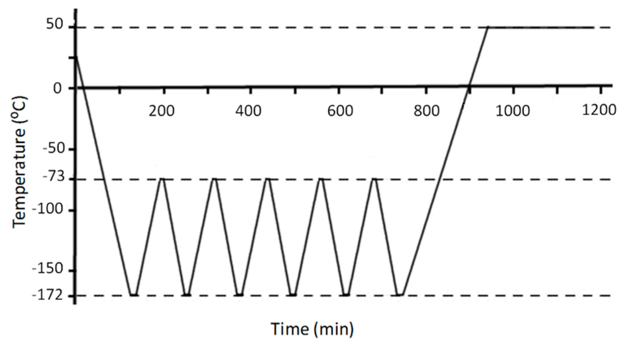
The heat treatment process parameters followed by the samples can be seen in Table 2. A multistage DCT was applied to Sample 2 instead of the traditional isothermal DCT. With the multistage DCT, materials undergo several stepwise controlled cryogenic temperature cycles. Subsequent heating and cooling induce a mechanical contraction–expansion effect that overlaps the mere thermal effect, making treatment more effective. It reduces the DCT duration from 36–24 h to 15 h, therefore achieving the same mechanical properties as conventional DCT with lower nitrogen consumption [30]. Multistage DCT parameters were taken from a previous research [30].
In order to study the effect of the parameters considered in this work, two different samples were produced as a result of applying different heat treatments, as presented in Table 2. The sample sizes were 100 mm × 80 mm × 15 mm. These samples size correspond with the dimensions of a typical cutting shear blade made with AISI A8 alloy for industrial use—80 mm height × 15 mm thickness. Due to the relatively small thickness of the samples, forced air quenching at room temperature was used instead of oil quenching in this study. The final hardness achieved in this case was 57 HRC for both samples.
2.2. Wear Test
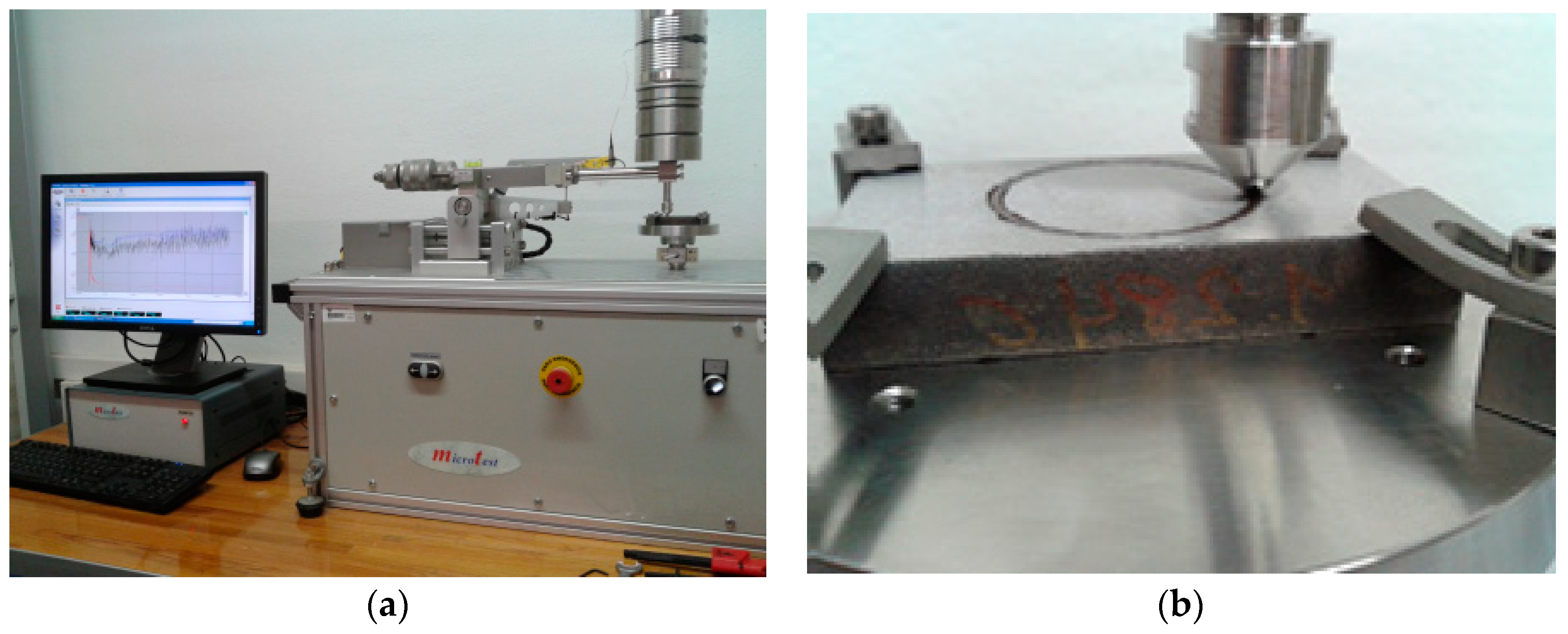
The pin-on-disk laboratory wear tests were run according to ASTM G99-05(2010) [31] using Microtest wear and friction pin-on-disk test equipment computerized with MT4002 software (MT4002, Microtest, Madrid, Spain) for the control, data acquisition, and data processing (see Figure 2).
The experimental parameters used for the wear test are as follows. All sample surfaces were ground to 0.8 µm Ra surface quality according to the ASTM G99-05(2010) standard. The angular velocity of the testing machine was adjusted to 0.3 m/s linear speed and the load was established at 100 N. All experiments were run for a 500 m distance. These parameters were chosen based on those used by other researchers to analyze the benefits of cryogenic treatment on the wear behavior of several tool steels [32]. A 6 mm diameter tungsten carbide (WC) ball was attached to the testing machine as a counter material. A WC ball was used since it has very good wear properties and hardness appropriate for use as a counter ball, and it has been previously used for this purpose [26]. Tests were performed three times for each sample. These parameters are summarized in Table 3.
2.3. Microstructure
The microstructure of the materials was observed on a JEOL JSM-7000F scanning electron microscope (SEM) (JEOL Ltd., Tokyo, Japan) and the obtained images were analyzed using Fiji software (public domain software) [33] to quantify the carbide sizes and their distribution for each sample.
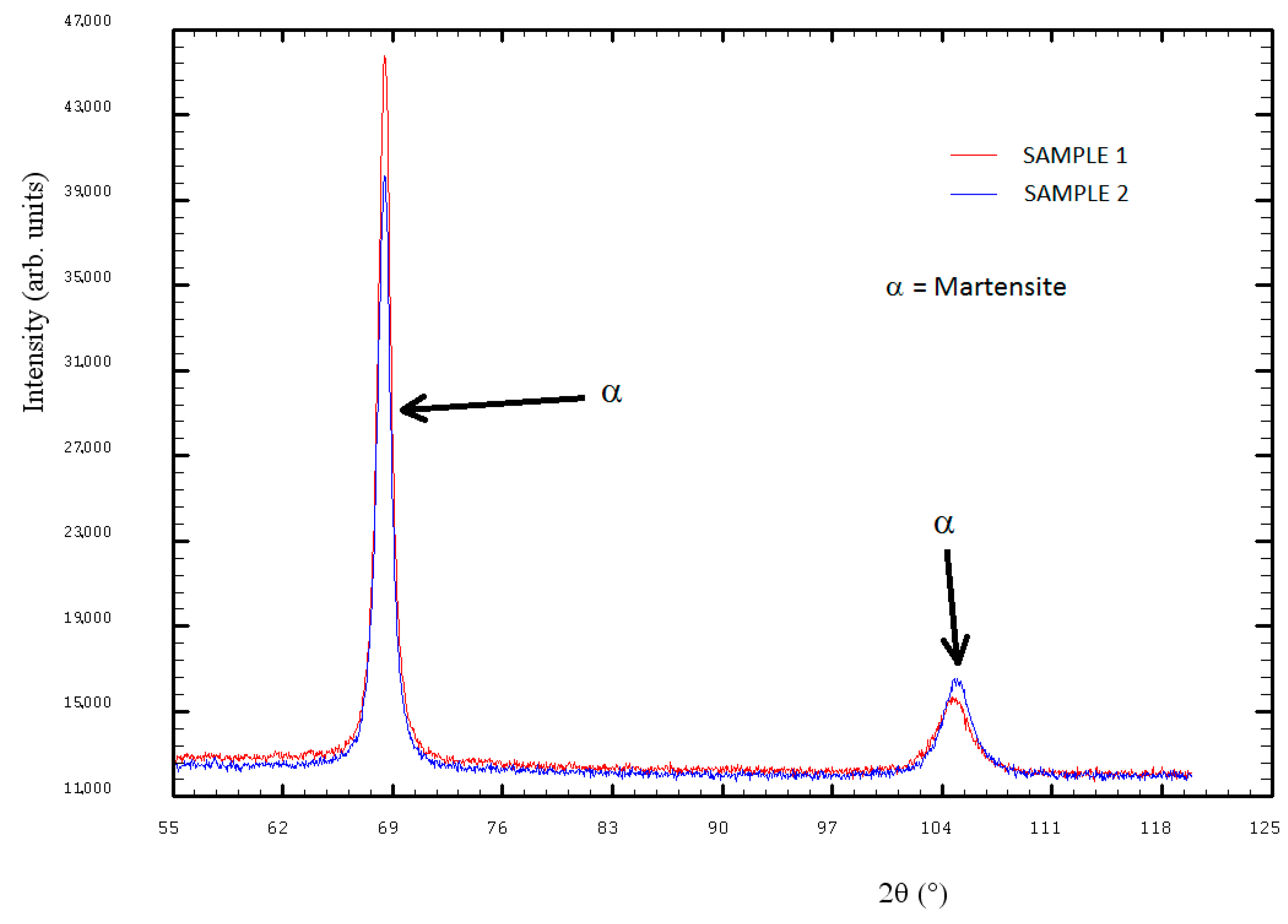
The microstructure was formed by a martensitic matrix with small carbides distributed for Sample 1 and Sample 2, as it can be seen in Figure 3 and Figure 4, and in the X-ray diffraction (Bruker Corporation, Billerica, Massachusetts, USA) lines of Figure 5.
Figure 4 shows a higher magnification SEM image of the two samples where the martensitic structure is appreciated.
For the AISI A8 alloy, there was no retained austenite transformation into martensite during the cryogenic treatment since all of the austenite was transformed into martensite during quenching, or at least its amount was below 2%, which is the minimum amount of a phase required to be detected with the X-ray diffraction (XRD) equipment used in this study (see Figure 5). Therefore, the influence of the cryogenic treatment could only be observed by analyzing the precipitation of the carbides.
2.4. Internal Residual Stress
A Bruker D8 Discover diffractometer (Bruker Corporation, Billerica, MA, USA) was used to measure the internal residual stresses of the samples. This equipment was equipped with a Cr Twist tube, PolyCapTM (1 µ single crystal cylinders) system for parallel beam generation (divergence of 0.25°), a V filter (λ = 2.2911 Å), and a 1-D LynxEye detector (Bruker Corporation, Billerica, MA, USA) (active length in 2θ 2.7°). Data were collected from 151° to 160° 2θ (step size = 0.05 and time per step = 5 s), mounted on a Eulerian cradle with an automatically controlled X-Y-Z stage.
The stress measurements using X-ray diffraction are basically strain measurements in crystalline regions—the stresses can be calculated from the measured strains when the elastic constants are known. In a polycrystalline material with many crystals in random orientations, a measuring vector nψϕ must be introduced, describing the orientation of an experimental selected {hkl}-net plane normal with respect to the sample coordinate system, by the azimuth angle ϕ(phi) and a tilt angle ψ(Psi). Obviously, the strain εψϕ (in the direction of nψϕ) also depends on the azimuth and tilt angles.
The procedure for stress measurements in a sample can be performed by changing the tilt angle at a constant azimuthal angle; when the measured strains are plotted versus Sin2ψ, an X-ray stress analysis can be performed. The traditional Strain–Sin2ψ method [34,35,36] is based on the elastic theory of an isotropic solid that depends on the linear relation of measured diffraction strain ε and Sin2ψ, where ψ is the tilt angle of the specimen (i.e., the inclination of the lattice–strain measurement direction with respect to the direction normal to the surface of the specimen). The stress can be obtained from the slope of the straight line fitted to the measured ε–Sin2ψ plot. The linear relation of ε and Sin2ψ is effective for the analysis of a homogeneous stress state in a macroscopically isotropic elastic specimen.
Strain values were recorded in side inclination mode for different sample tilt angles (Psi) over seven steps, 0–0.7 range in Sin2ψ (0, 9.47, 18.93, 28.40, 37.86, 47.32, and 56.79°) at constant azimuth angles (phi). To estimate the stress values, Strain vs. Sin2ψ was plotted. At least six measurements are needed on Strain-Sin2ψ plot using three different values of (phi) in order to acquire a complete evaluation, so 0°, 45°, and 90° were chosen in negative and positive values.
The internal stresses were measured in the section transversal to the rolling direction. Samples were mechanically polished and finally electrolytically polished to eliminate any possible deformation on the surface of the samples created during the mechanical cutting/polish process before the measurements.
3. Results and Discussion
3.1. Wear
Pin-on-disk tested samples were measured using a computer-controlled Taylor Hobson surface profiler. From this surface profiler, the wear track profile was obtained and finally the wear rate was calculated. In Figure 6, the distribution of the experiments wear rates and the mean value are plotted for the two samples.
The wear rate results revealed an improvement in the wear resistance of the cryogenically treated Sample 2. This improvement was about a 14% of reduction in its wear rate. One-way analysis of variance (ANOVA) was performed as well to decide whether there were significant differences between the means of the two classes. In this case, the p-value was 0.249, which provides weak evidence that the null hypothesis does not hold. However, as only two classes are compared, we can say that the classes are different, so the DCT improved the properties of the material even if this improvement is not very significant. These results were in good agreement with those obtained by Pillai et al. [29].
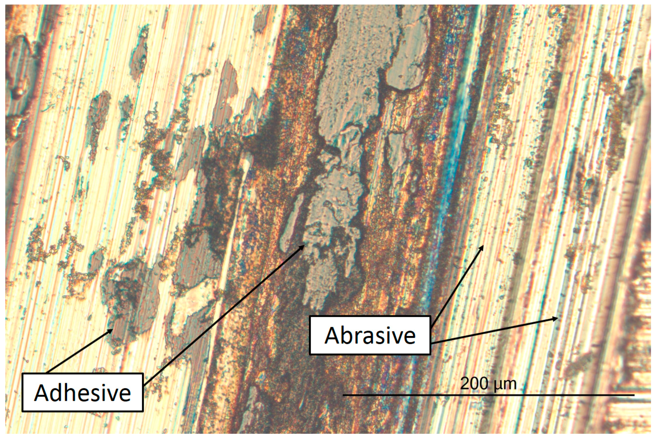
The wear track obtained after the laboratory tests can be observed in the Figure 7. The wear mechanism observed in both samples is a combination of adhesive and abrasive wear.
3.2. Microstructure
The secondary carbides were quantitatively analyzed to study the influence of the DCT on the microstructure of AISI A8.
First, the SEM micrographs were binarized using the Auto Local Threshold plugin (see Figure 8) and they were then automatically analyzed using the Sauvola algorithm.
After this procedure, the following information for the carbides was obtained: centroid positions (the mean position of all the points in all of the coordinate directions), and the number of particles and their sizes. To calculate the distribution of the carbides, their centroids were used by computing the distances to the four closest neighbors and their averages using an script in MATLAB developed in-house [37].
From this procedure, the number of carbides present in each sample was quantified and the density of these particles per area was calculated along with their mean lengths and the percentage of the total occupied area. Results are shown in Table 4 with the standard deviations. The carbide distribution measurement method is described in greater detail in a previous study [38].
Study of the microstructure revealed an increase of 6% in the number of carbides for Sample 2. We can conclude that a precipitation of new fine carbides occurred when AISI A8 was cryogenically treated since the area occupied by them increased while their mean length was reduced.
3.3. Carbide Distribution
As previously mentioned, carbide centroids were used to compute the four closest neighbors and their averages in order to calculate their distribution (see Figure 9).
Figure 9 shows that the average distances among the carbide particles had a smaller dispersion for the cryogenically treated sample (Sample 2). This means that the precipitation of carbides due to the cryogenic treatment took place all over the sample in a more homogeneous way and it was not restricted to a limited area or areas. The new carbides precipitated with the DCT into the previous carbide interspaces, giving rise to smaller distances between particles, and thus a more homogeneous distribution.
3.4. Internal Stress
Internal stress measurements revealed very similar results for both samples with values around 0 MPa in both cases. These internal stresses obtained in the section transversal to the rolling direction were similar in both axes. Even if a compression stress was delivered in one of the directions measured during the rolling process, all the internal stresses disappeared due to the tempering treatments followed by the samples. No differences regarding the influence of the DCT after the tempering were measured. Therefore, we can conclude that the internal stress was not influenced by the cryogenic treatment for the case studied in the present work.
4. Conclusions
The wear of the AISI A8 tool steel was augmented when it was subjected to deep cryogenic treatment. This improvement was 14% for the laboratory tests in comparison with the conventionally treated sample.
The study of the microstructure revealed an increase in the number of secondary carbides for the cryogenically treated samples since their density was 12.5% higher. The final microstructures of the cryogenically treated samples had more carbides, covered a larger area, and were more homogeneously distributed than those in the conventionally treated samples. This increase in the number of homogeneously distributed carbides can explain the improvement in wear resistance.
The internal residual stress of the AISI A8 alloy was not influenced by DCT for the case studied in the present work. The final tempering applied to both samples may be the reason for the total relaxation of the internal stresses.
A multistage DCT was presented in this work. Results revealed an improvement of the wear resistance of the AISI A8 tool steel as it contributed to the precipitation of fine secondary carbides. Besides these improvements of mechanical properties, the DCT process itself was also improved by a reduced duration when compared with the conventional DCT.
Author Contributions
Methodology, P.J.; Investigation, P.J.; Project administration, P.J.; Writing—original draft, P.J.; Software, M.I.; Data curation, M.I. and J.I.; Validation, R.F.-M.; Writing—review and editing, R.F.-M. and J.I.
Funding
This research was funded by the Department of Industry, Innovation, Trade, and Tourism of the Basque Country Government through the S-PE12UN080 SAIOTEK project.
Acknowledgments
The authors are grateful for the technical and human support provided by SGIker of UPV/EHU and European funding (ERDF and ESF).
Conflicts of Interest
The authors declare no conflict of interest.
References
- Akincioğlu, S.; Gökkaya, H.; Uygur, I. A review of cryogenic treatment on cutting tools. Int. J. Adv. Manuf. Technol. 2015, 78, 1609–1627. [Google Scholar] [CrossRef]
- Baldissera, P.; Delprete, C. Deep Cryogenic Treatment: A Bibliographic Review. Open Mech. Eng. J. 2008, 2, 1–11. [Google Scholar] [CrossRef]
- Collins, D.N.; Dormer, J. Deep cryogenic treatment of a D2 cold-worked tool steel. Heat Treat. Met. 1997, 3, 71–74. [Google Scholar]
- Barron, R.F. Cryogenic treatment of metals to improve wear resistance. Cryogenics 1982, 22, 409–413. [Google Scholar] [CrossRef]
- da Silva, F.J.; Franco, S.D.; Ezugwu, E.O.; Souza, A.M., Jr. Performance of cryogenically treated HSS tools. Wear 2006, 261, 674–685. [Google Scholar] [CrossRef]
- Mohan Lal, D.; Renganarayanan, S.; Kalanidhi, A. Cryogenic treatment to augment wear resistance of tool and die steels. Cryogenics 2001, 41, 149–155. [Google Scholar] [CrossRef]
- Huang, J.Y.; Zhu, Y.T.; Liao, X.Z.; Beyerlein, I.J.; Bourke, M.A.; Mitchell, T.E. Microstructure of cryogenic treated M2 tool steel. Mater. Sci. Eng. A 2003, 339, 241–244. [Google Scholar] [CrossRef]
- Akhbarizadeh, A.; Shafyei, A.; Golozar, M.A. Effects of cryogenic treatment on wear behavior of D6 tool steel. Mater. Des. 2009, 30, 3259–3264. [Google Scholar] [CrossRef]
- Meng, F.; Tagashira, K.; Sohma, H. Wear resistance and microstructure of cryogenic treated. Fe-1.4Cr-1C bearing steel. Scr. Metall. Mater. 1994, 31, 865–868. [Google Scholar] [CrossRef]
- Das, D.; Dutta, A.K.; Ray, K.K. Sub-zero treatments of AISI D2 steel: Part I. Microstructure and hardness. Mater. Sci. Eng. A 2010, 527, 2182–2193. [Google Scholar] [CrossRef]
- Das, D.; Dutta, A.K.; Ray, K.K. Influence of temperature of sub-zero treatments on the wear behaviour of die steel. Wear 2009, 267, 1361–1370. [Google Scholar] [CrossRef]
- Bensely, A.; Venkatesh, S.; Mohan Lal, D.; Nagarajan, G.; Rajadurai, A.; Junik, K. Effect of cryogenic treatment on distribution of residual stress in case carburized En 353 steel. Mater. Sci. Eng. A 2008, 479, 229–235. [Google Scholar] [CrossRef]
- Oppenkowski, A.; Weber, S.; Theisen, W. Evaluation of factors influencing deep cryogenic treatment that affect the properties of tool steels. J. Mater. Process. Technol. 2010, 210, 1949–1955. [Google Scholar] [CrossRef]
- Das, D.; Dutta, A.K.; Ray, K.K. Inconsistent wear behaviour of cryotreated tool steels: Role of mode and mechanism. Mater. Sci. Technol. 2009, 25, 1249–1257. [Google Scholar] [CrossRef]
- Darwin, J.D.; Mohan Lal, D.; Nagarajan, G. Optimization of cryogenic treatment to maximize the wear resistance of 18% Cr martensitic stainless steel by Taguchi method. J. Mater. Process. Technol. 2008, 195, 241–247. [Google Scholar] [CrossRef]
- Molinari, A.; Pellizzari, M.; Gialanella, S.; Straffelini, G.; Stiasny, K.H. Effect of deep cryogenic treatment on the mechanical properties of tool steels. J. Mater. Process. Technol. 2001, 118, 350–355. [Google Scholar] [CrossRef]
- Meng, F.; Tagashira, T.; Azuma, R.; Sohma, H. Role of eta-carbide precipitations in the wear-resistance improvements of Fe-12Cr-Mo-V-1.4C tool steel by cryogenic treatment. ISIJ Int. 1994, 34, 205–210. [Google Scholar] [CrossRef]
- Pérez, M.; Belzunce, F.J. The effect of deep cryogenic treatments on the mechanical properties of an AISI H13 steel. Mater. Sci. Eng. 2015, 624, 32–40. [Google Scholar] [CrossRef]
- Preciado, M.; Bravo, P.M.; Cárdenas, D. Deep cryogenic treatment of HPDC AZ91 magnesium alloys prior to aging and its influence on alloy microstructure and mechanical properties. J. Mater. Process. Technol. 2017, 239, 297–302. [Google Scholar] [CrossRef]
- Dieringa, H. Influence of Cryogenic Temperatures on the Microstructure and Mechanical Properties of Magnesium Alloys: A Review. Metals 2017, 7, 38. [Google Scholar] [CrossRef]
- Li, H.; Tong, W.; Cui, J.; Zhang, H.; Chen, L.; Zuo, L. The influence of deep cryogenic treatment on the properties of high-vanadium alloy steel. Mater. Sci. Eng. A 2016, 662, 356–362. [Google Scholar] [CrossRef]
- Xu, L.Y.; Zhu, J.; Jing, H.Y.; Zhao, L.; Lv, X.Q.; Han, Y.D. Effects of deep cryogenic treatment on the residual stress and mechanical properties of electron-beam-welded Ti–6Al–4V joints. Mater. Sci. Eng. A 2016, 673, 503–510. [Google Scholar] [CrossRef]
- Wang, J.; Fu, R.; Li, Y.; Zhang, J. Effects of deep cryogenic treatment and low-temperature aging on the mechanical properties of friction-stir-welded joints of 2024-T351 aluminum alloy. Mater. Sci. Eng. A 2014, 609, 147–153. [Google Scholar] [CrossRef]
- Ramesh, S.; Bhuvaneswari, B.; Palani, G.S.; Lal, D.M.; Iyer, N.R. Effects on corrosion resistance of rebar subjected to deep cryogenic treatment. J. Mech. Sci. Technol. 2017, 31, 123–132. [Google Scholar] [CrossRef]
- Gong, X.; Wu, Z.; Zhao, F. Effect of Deep Cryogenic Treatment on the Microstructure and the Corrosion Resistance of AZ61 Magnesium Alloy Welded Joint. Metals 2017, 7, 179. [Google Scholar] [CrossRef]
- Koneshlou, M.; Meshinchi Asl, K.; Khomamizadeh, F. Effect of cryogenic treatment on microstructure, mechanical and wear behaviors of AISI H13 hot work tool steel. Cryogenics 2011, 51, 55–61. [Google Scholar] [CrossRef]
- Katoch, S.; Sehgal, R.; Singh, V. Optimization of friction and wear characteristics of varied cryogenically treated hot die steel grade AISI-H13 under dry condition. Friction 2017, 5, 66–86. [Google Scholar] [CrossRef] [Green Version]
- Bhawar, V.; Khot, S.; Kattire, P.; Mehta, M.; Singh, R. Influence of Deep Cryogenic Treatment (DCT) on Thermo Mechanical Performance of AISI H13 Tool Steel. J. Mater. Sci. Chem. Eng. 2017, 5, 91–101. [Google Scholar] [CrossRef]
- Pillai, N.; Karthikeyan, R. Effect of Deep Cryogenic treatment on AISI A8 Tool steel & Development of Wear Mechanism maps using Fuzzy Clustering. IOP Conf. Ser. Mater. Sci. Eng. 2018, 346, 012006. [Google Scholar] [Green Version]
- Martínez, E.; Climent, V.; Toneu, X. Actas del VI Congreso Ibérico de Tribología-Ibertrib 2011; Universidad Rey Juan Carlos: Madrid, Spain, 2011; ISBN 978-84-694-5705-4. [Google Scholar]
- ASTM G99-05, Standard Test Method for Wear Testing with a Pin-On-Disk Apparatus; ASTM Book of Standards: West Conshohocken, PA, USA, 2010.
- Das, D.; Dutta, A.K.; Ray, K.K. Influence of varied cryotreatment on the wear behavior of AISI D2 steel. Wear 2009, 266, 297–3009. [Google Scholar] [CrossRef]
- Schindelin, J.; Arganda-Carreras, I.; Frise, E.; Kaynig, V.; Longair, M.; Pietzsch, T.; Preibisch, S.; Rueden, C.; Saalfeld, S.; Schmid, B. Fiji: An open-source platform for biological-image analysis. Nat. Methods. 2012, 9, 676–682. [Google Scholar] [CrossRef] [PubMed]
- Müller, P.; Macherauch, E. Das Sin2ψ Verfahren der röntgenographischen Spannungsmessung. Z. Angew. Phys. 1961, 13, 305–312. [Google Scholar]
- Fitzpatrick, M.E.; Fry, A.T.; Holdway, P.; Kandil, F.A.; Shackleton, J.; Suominen, L. Measurement Good Practice Guide No. 52, Determination of Residual Stresses by X-ray Diffraction—Issue 2; National Physical Laboratory Teddington: Middlesex, UK, 2005; pp. 1–68. ISSN 1744–3911. [Google Scholar]
- Vermeulen, A.C.; JCPDS-International Centre for Diffraction Data. An Elastic Constants Database and XEC Calculator for Use in XRD Residual Stress Analisys. Adv. X-ray Anal. 2001, 44, 128–133. [Google Scholar]
- MATLAB Release; The MathWorks, Inc.: Natick, MA, USA, 2014.
- Jimbert, P.; Iturrondobeitia, M.; Ibarretxe, J.; Fernandez-Martinez, R. Carbide distribution based on automatic image analysis for cryogenically treated tool steels. Mater. Tehnol. 2017, 51, 609–611. [Google Scholar] [CrossRef]
Figure 1.
Cryogenic multistage treatment performed on Sample 2.

Figure 2.
Pin-on-disk laboratory test equipment used for the experiments (a) and detail of the wear track created by the turning the tungsten carbide (WC) counter ball over the sample surface (b).
Figure 2.
Pin-on-disk laboratory test equipment used for the experiments (a) and detail of the wear track created by the turning the tungsten carbide (WC) counter ball over the sample surface (b).

Figure 3.
SEM image of the microstructure of the AISI A8 tool steel for Sample 1. Several secondary carbides are identified in a martensitic matrix.
Figure 3.
SEM image of the microstructure of the AISI A8 tool steel for Sample 1. Several secondary carbides are identified in a martensitic matrix.

Figure 4.
SEM images of the Sample 1 (a) and Sample 2 (b) microstructures. The martensitic structure can be appreciated in both cases.
Figure 4.
SEM images of the Sample 1 (a) and Sample 2 (b) microstructures. The martensitic structure can be appreciated in both cases.

Figure 5.
X-ray diffractograms of Sample 1 and Sample 2.

Figure 6.
Wear rate obtained for the different heat treatment processes followed by samples of AISI A8 tool steel.
Figure 6.
Wear rate obtained for the different heat treatment processes followed by samples of AISI A8 tool steel.

Figure 7.
Micrograph of the wear track of Sample 2 where the different wear mechanisms can be observed.
Figure 7.
Micrograph of the wear track of Sample 2 where the different wear mechanisms can be observed.

Figure 8.
Original SEM image of Sample 1 (a) and the same image after binarization with the same scale for image analysis (b).
Figure 8.
Original SEM image of Sample 1 (a) and the same image after binarization with the same scale for image analysis (b).

Figure 9.
Carbide distribution for Samples 1 and 2.


Table 1.
Chemical composition in weight percentage for the studied tool steel and Rockwell C hardness after conventional heat treatment.
Table 1.
Chemical composition in weight percentage for the studied tool steel and Rockwell C hardness after conventional heat treatment.
| Material | C | Mn | Si | Cr | Ni | Mo | W | Hardness |
|---|---|---|---|---|---|---|---|---|
| AISI A8 | 0.5–0.6 | 0.5 | 0.75–1.1 | 4.75–5.5 | 0.3 | 1.15–1.65 | 1–1.5 | 48–57 (HRC) |
Table 2.
Different heat treatment processes applied to the AISI A8 tool steel samples.
| Sample | Processing Sequences | |||
|---|---|---|---|---|
| 1 | Heat-treated at 1050 °C for 30 min followed by forced air quenching | Tempered at 500 °C for 90 min | Tempered at 500 °C for 90 min | |
| 2 | Heat-treated at 1050 °C for 30 min followed by forced air quenching | Multistage deep cryogenic treatment (DCT) (see Figure 1) | Tempered at 500 °C for 90 min | Tempered at 500 °C for 90 min |
Table 3.
Parameters used for the pin-on-disk laboratory wear tests.
| Shape of the Sample | Counter Body | Normal Load (N) | Sliding Velocity (m/s) | Total Sliding Distance (m) |
|---|---|---|---|---|
| Disc | WC ball | 100 | 0.3 | 500 |
Table 4.
Density, length, and area occupied by the carbides for Samples 1 and 2.
| Sample | Density (Particles/µm2) | Mean Length (µm) | Area Occupied (%) |
|---|---|---|---|
| 1 | 0.168 ± 0.09 | 1.53 ± 0.4 | 0.68 ± 0.3 |
| 2 | 0.189 ± 0.06 | 1.43 ± 0.4 | 0.73 ± 0.2 |
© 2018 by the authors. Licensee MDPI, Basel, Switzerland. This article is an open access article distributed under the terms and conditions of the Creative Commons Attribution (CC BY) license (http://creativecommons.org/licenses/by/4.0/).
Share and Cite
MDPI and ACS Style
Jimbert, P.; Iturrondobeitia, M.; Ibarretxe, J.; Fernandez-Martinez, R. Influence of Cryogenic Treatment on Wear Resistance and Microstructure of AISI A8 Tool Steel. Metals 2018, 8, 1038. https://doi.org/10.3390/met8121038
AMA Style
Jimbert P, Iturrondobeitia M, Ibarretxe J, Fernandez-Martinez R. Influence of Cryogenic Treatment on Wear Resistance and Microstructure of AISI A8 Tool Steel. Metals. 2018; 8(12):1038. https://doi.org/10.3390/met8121038
Chicago/Turabian StyleJimbert, Pello, Maider Iturrondobeitia, Julen Ibarretxe, and Roberto Fernandez-Martinez. 2018. "Influence of Cryogenic Treatment on Wear Resistance and Microstructure of AISI A8 Tool Steel" Metals 8, no. 12: 1038. https://doi.org/10.3390/met8121038
Note that from the first issue of 2016, this journal uses article numbers instead of page numbers. See further details here.