Article

Uniaxial Low-Cycle Fatigue Study of Alloy 800H Weldments at 700 °C

1
Department of Mechanical Design Engineering, Pukyong National University, Busan 48513, Korea
2
Regional Technological Institute, Research Centre of the Faculty of Mechanical Engineering, University of West Bohemia, Univerzitni 8, 306 14 Pilsen, Czech Republic
3
Korea Atomic Energy Research Institute (KAERI), Daejeon 34057, Korea
*
Author to whom correspondence should be addressed.
Metals 2018, 8(11), 918; https://doi.org/10.3390/met8110918
Submission received: 21 October 2018 / Revised: 5 November 2018 / Accepted: 5 November 2018 / Published: 7 November 2018

Abstract

:
Alloy 800H is currently under consideration to be used in a very high temperature reactor system. This paper describes the experimental low-cycle fatigue study on Alloy 800H base metal and weldments in the air with fully-reversed strain control at 700 °C. The recommended modern Alloy 800H weldments were fabricated by gas tungsten arc welding. The observed fatigue life is found to be comparable between base metal and weldments at this temperature, indicating the welding technique can compete with base material. The influence of hold time was further investigated at the maximum tensile strain of 0.6% total strain range condition for 60 s, and it is found to reduce the fatigue life. For most of the tests, the base metal revealed an initial cyclic hardening stress response, otherwise, the weldment was entirely softened with cycles. The addition of hold time is also found to induce an unequal cyclic stress response in both materials. Accordingly, for continuous low-cycle fatigue tests, fatigue cracks were initiated and propagated in a classical transgranular fracture mode. However, the hold time affected the mixed-mode fracture mode by means of a transition from transgranular to intergranular fracture.

1. Introduction

Alloy 800H is one of the near-term alternative candidate materials for Alloy 617 and 230 to be used in components of intermediate heat exchangers (IHX) for the very high temperature reactor (VHTR) system in the Generation-IV (Gen-IV) nuclear concept with helium as the primary coolant [1]. The VHTR has a design outlet temperature (up to 950 °C), leading to excellent thermal efficiencies, and can serve as process heat for hydrogen production [2]. At this critical temperature, such low-cycle fatigue (LCF), creep, and creep-fatigue (CF) loadings, which represent a major damage mode from the startup and shutdown system, as well as temperature gradient provided by thermal-mechanical loading during the operation, become very important [3,4]. The current criteria for design of elevated temperature components, bearing on the American Society of Mechanical Engineer Boiler and Pressure Vessel Code (ASME B&PV code) Section 3 Subsection NH of Alloy 800H for nuclear service, is up to 760 °C [1,2]. Although it will finally be used in the helium environment of the VHTR, the acceptable design in the ASME B&PV code refers to the time-dependent behavior in air. Therefore, elevated temperature characterization of this alloy such as the influence of hold-time (HT) due to the time-dependent deformation mechanism like creep is also necessary, including interest to extend its application beyond 760 °C to be utilized in nuclear components.
Alloy 800H has been extensively studied in the past decades for nuclear construction. M. Kolluri et al. [3] investigated the high temperature tensile, LCF, and CF interactions of Alloy 800H to be used in the VHTR system. The temperature for LCF and CF tests was set at 800 °C. They also investigated the tungsten inert gas welded specimens for high temperature tensile tests at three different temperatures, 21, 700, and 800 °C. J.L. Kaae [4] reported the LCF tests for Alloy 800H in the temperature range of 22–760 °C at studied axial strain controls of 2%–0.3%. K.B.S. Rao et al. [5,6] reported the LCF experimental study of Alloy 800H in the temperature range from 750 to 950 °C with different strain rates and waveform shape (fast-fast; slow-slow; fast-slow; slow-fast tests). However, most of the literature studies report on the fatigue behavior for Alloy 800H base material only. Apart from that, joints by welding techniques also become a very important consideration in a large structure owing to their heterogeneity in microstructures [7]. Current research regarding Alloy 800H weldments is very rare at several strain and stress range conditions. Therefore, this paper focuses on the experimental study of the LCF behavior of Alloy 800H base metal (BM) and its weldments, which were fabricated by the gas tungsten arc welding (GTAW) process, at a target temperature of 700 °C for service reliability assessment of welded structures. The influence of HT with 60 s HT at the maximum tensile strain is further examined to understand the effect on both materials’ LCF life and their fracture mechanism. Finally, the microstructure of selected specimens is examined.

2. Materials and Methods

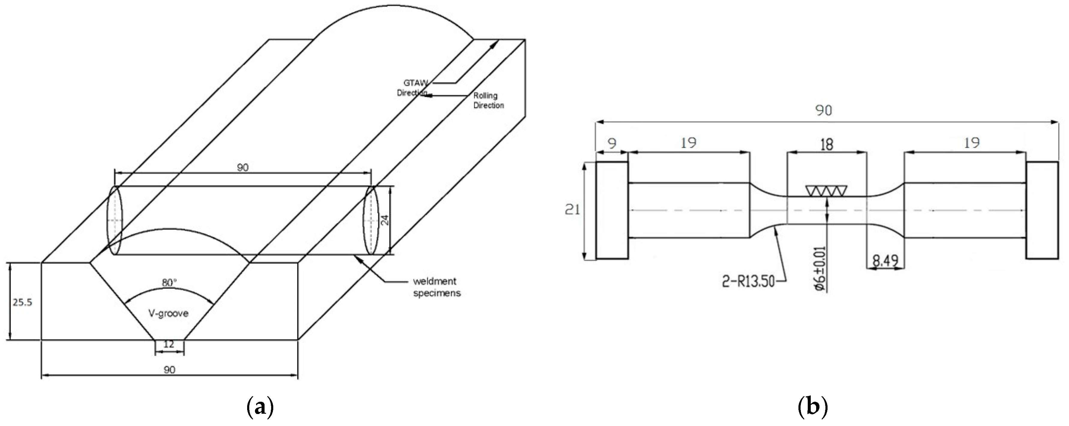
2.1. Alloy 800H and Welding Procedures

Alloy 800H is an austenitic iron–nickel base superalloy with arranged contents of carbon (0.05–0.10 wt.%), aluminum and titanium (Al + Ti (0.85–1.20 wt.%)), silicon, and manganese [3]. Table 1 shows the chemical composition of the Alloy 800H and its filler wire (wt.%.) used in this study. Elements of C, Ti, and Al have a significant effect on the high temperature mechanical properties because of the precipitation reaction during aging. Alloy 800H is normally obtained with elements such as Ni and Cr ensuring the austenitic structure at room temperature and high chemical stability at elevated temperatures. The primary carbide, Ti(C,N), occurs when the titanium and carbon are drawn out of the material and react in the atmosphere and it is known to be favorable at high temperatures.
The GTAW procedure was used to join the two plates of Alloy 800H with a filler metal of KW-T82 under 99.9% pure argon atmosphere to shield the welding pool. This GTAW condition used a direct current straight polarity (DCSP) with a stable power arc and low electrode consumption. The welding current was varied between 14 and 16 volts, and the welding speed range was about 18–22 cm/min. The minimum preheating temperature was 18 °C, and the temperature between passes under 177 °C. During the GTAW process, 15 welding layers and 47 passes were employed with an 80° V-groove gap. Accordingly, ultrasonic inspection, tensile, and bending tests were performed after welding for flaw detection and material qualification.

2.2. Test Methods

The microhardness and microstructure across the weldments have first been done for initial characterization. For the uniaxial LCF test, a hot-rolled Alloy 800H plate with a thickness of 25.5 mm was used in this study. The test matrix of LCF tests in this study is given in Table 2. Cylindrical LCF button head specimens were extracted from the plate (also weldments plate) with a gauge length of 12 mm and diameter of 6 mm in the reduced section. That is to say that the high temperature extensometer was attached axially to the gauge section for collecting real-time strain data during the test. Figure 1 shows configuration of weldments plate and dimension of cylindrical LCF specimen used in this study. All weldments specimens were prepared in accordance with Section IX of the ASME B&PV code. The LCF specimens for weldments were horizontally extracted to the welding direction from the weldments plate. The width of the weld including the heat affected zone (HAZ) varied from 12 to 13 mm, with HAZ specifically ~1 mm in the range, but does not exceed the limited range of the extensometer (a reference gauge length of 12.0 mm). Thus, the gauge section for weldments consist of weld and HAZ materials only.
A series of LCF tests was performed under fully reversed strain control (R = −1) in the air with different total strain ranges of 0.6%, 0.9%, 1.2%, and 1.5% at target temperature of 700 °C. The LCF tests were conducted in servohydraulic fatigue testing equipment (MTS 370 Landmark, Pierre, SD, USA, 100 kN) with a tube furnace. The target temperature was only allowed to vary about ±2 °C. Before the commencement of the test, the target temperature was held at zero stress level for 30 min to allow the temperature to stabilize. The LCF tests were carried out under triangular waveform in a constant strain rate of 10−3 s−1. For LCF tests with HT, the HT was applied at the maximum tensile strain of 0.6% total strain range for 60 s under fully reversed trapezoidal waveform. The LCF tests were terminated until specimen fractured and the LCF life criterion was defined as a 20% drop in the stress ratio (peak tensile over compressive stress). Metallographic studies were carried out through an optical microscope (OM, JP/GX51, Olympus Corp., Tokyo, Japan) and scanning electron microscope (SEM, Hitach JEOL JSM 5610, JEOL, Tokyo, Japan) with an energy-dispersive X-ray spectroscopy (Oxford EDS system, High Wycombe, UK) facility to identify the element constituents of the materials. The true microstructure was revealed through the chemical etching using Marble’s reagent.

3. Results and Discussion

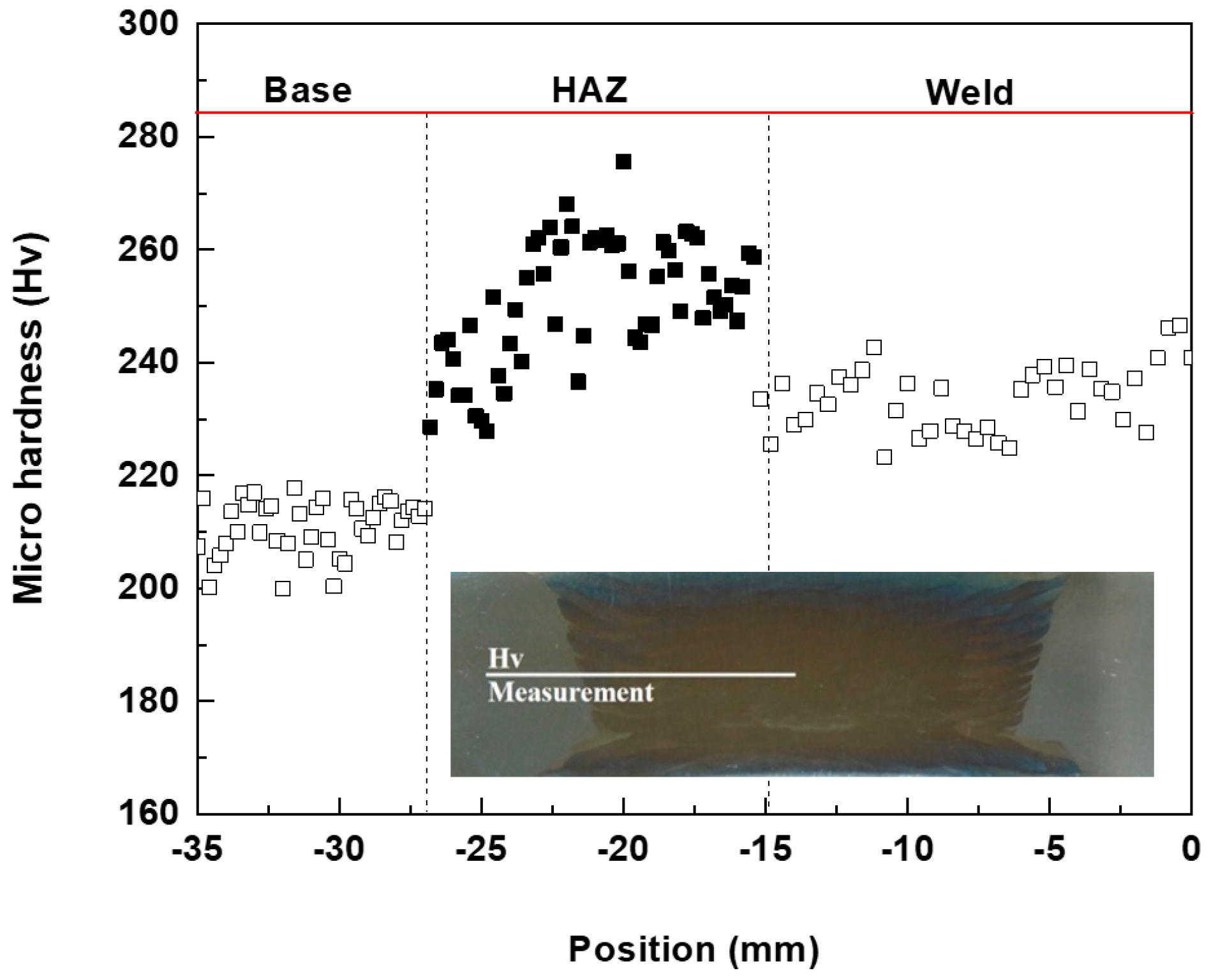
3.1. Initial Microstructure and Microhardness

Alloy 800H is the face centre cubic (FCC) fully austenitic solid solution nickel–iron–chromium alloy. Figure 2a–c shows the optical micrographs of the BM, weld, and heat affected zone (HAZ), respectively. Figure 2a shows large equiaxed grains with coarse grain size of about 120–200 µm, offering stability at high temperatures. The alloy is known to have a uniform distribution of γ’-precipitates within γ-matrix. Because of the heat generation during welding, the dendritic morphology was formed in the weld. Figure 2b shows the weld region is encompassed of austenitic columnar grains with dendritic structure [8]. The precipitates are expected to form along the solidification of grain boundary (GB). Lastly, the heat affected zone (HAZ) of the weld was formed by carbide dissolution and a small amount of grain growth, as shown in Figure 2c. It can be associated with temperature rising during welding. Figure 3 shows microhardness results of the Alloy 800H weldment. The measurement was performed along the center line of the plate. It is observed that the weld has a higher microhardness than the BM, and significantly increases in the HAZ. From these observations, the weldments are stronger, which causes the stress raisers due to the morphology of dendrites compared with the BM.

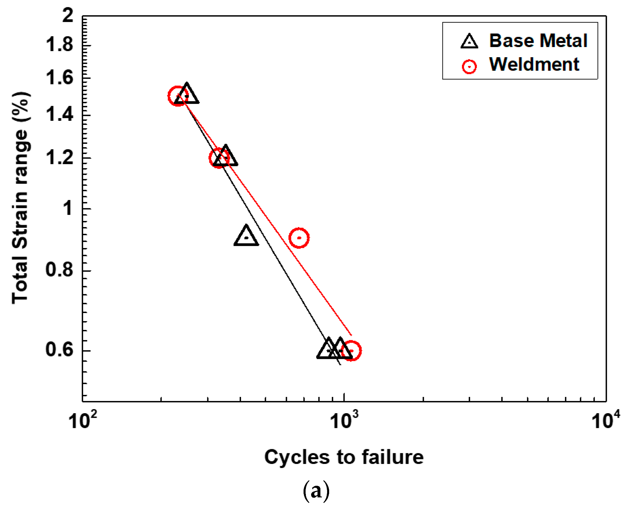
3.2. Low-Cycle Fatigue Properties

Figure 4 shows LCF life graphs for BM and weldments, respectively. From Figure 4a, it is observed that the LCF life of BM and weldments is comparable at this temperature. From the result, the weldments have a longer life at lower total strain ranges and a lower life at higher total strain ranges compared with the BM. It is found that the welding technique can compete with base material performance. Most of the test results show that the increase of the total strain range reduces the LCF life. Figure 4b shows that the addition of HT at maximum tensile strain during LCF testing also significantly reduces the LCF life of both materials. The HT reduces the LCF lifespan by a factor of approximately two compared with the LCF life. The influence of HT will be shown later in Section 3.3.
Figure 5a,b shows the peak tensile-compressive stresses for BM and weldments, respectively. It is shown that the tension-compression stresses are symmetrical during LCF testing. From Figure 5a, a hardening phase can be observed for all conditions until the first 100 cycles. The saturation regime is then noticed with a plateau in the peak stress. This result indicates that the cyclic stress response established a stable cycle after 100 cycles. Finally, a cyclic softening can be seen until a rapid drop of about 95% of total life. Similar findings can be found in the literature [3,4,5]. In the case of weldments in Figure 5b, the flow stress response is cyclically softened with cycles for the entire life. It should be carefully noted that in the weldments, the initial flow stress is much higher than the BM owing to its strength.
The mid-life hysteresis loops for BM and weldments are shown in Figure 6a,b, respectively. It is clear that both BM and weldments show a consistency with increases of total strain range. It is observed that the peak stress of weldments at mid-life is higher than that of the BM. Generally, the shape of the BM hysteresis loop is wider than that of the weldments, indicating the plastic strain range is higher compared with the weldments. Monotonic strain hardening can be noticed in both materials, which means the stress range is increased with the increasing of total strain range. For further interpretation, the cyclic stress–strain curves can be correlated with a cyclic Ramberg–Osgood relationship. This cyclic stress–strain relationship is given by Equation (1):
  Δ ε t 2 = Δ ε e 2 + Δ ε p 2 = Δ σ 2 E + ( Δ σ 2 K ) 1 / n  
where Δεt, Δσ, E, Δεp, Δεe, K’, and n’ represent the total strain range, stress range, elastic modulus, plastic and elastic strain range, fatigue strength coefficient, and fatigue strain hardening exponent, respectively. Based on this combination, the Masing behavior can be observed if the upper tips of the loops are all coincident. Thus, the shape of hysteresis loops for both studied materials exhibits a satisfactory Masing type behavior.
From the result, the serrated yielding can be observed for both materials during initial cycles. This finding also can be found for Alloy 800H BM from existing literatures [4,9]. Figure 7 shows typical stress–strain hysteresis loops indicating serrated yielding for BM at 1.5% total strain range. This serrated yielding is characterized by fluctuated load level during tension or compression stress, which is one of the manifestations of dynamic strain aging (DSA). The DSA itself is a strengthening mechanism during locking–unlocking dislocation motions by the diffusion of suspected metallic atoms (Chromium) causing serrated yielding [9]. After some cyclic loadings, the serrated flow had gradually vanished and the hysteresis loops become smooth, probably caused by an increase of dislocation density, and the interactions between solute atoms movement [4]. The DSA-induced embrittlement will possibly allow inhomogeneous deformation as GBs are preferred sites for DSA-cracking, resulting in a higher crack propagation rate. Based on Figure 7, however, the activities of serration flow stress are identical between the tensile and compression stages. Rodriguez [10] reported three principal types of serrated flow stress (Types A, B, and C) with respect to their characteristic on the stress–strain diagram. In the present study, the serrations belong to Type C, since the load drops occurred below the general level of the stress-strain curve as a result of the unlocking motion of dislocation. This type of serration generally occurs at higher temperatures.
The cycles to failure in the LCF test can be described by the well-known combining Coffin–Manson–Basquin (CMB) law:
  Δ ε t 2 = Δ ε e 2 + Δ ε p 2 = σ f E ( 2 N f ) b + ε f ( 2 N f ) c  
where σf’ and b are fatigue constants known as fatigue strength and exponent. εf’ and c are fatigue constants known as the fatigue ductility and exponent, respectively. Lastly, Nf represents the number of cycles to failure. The log–log plot of the CMB curves for BM and weldments is shown in Figure 8. Larger scattering can be noticed for the weldments compared with that of the BM following this rule. The CMB constants are listed in Table 3. It is shown that the c slope of weldments is slightly higher than that of the BM, which means the weldments had more deformability during LCF at this temperature. The transition of fatigue life, Nt, for BM is slightly longer when compared with that of the weldments—it is about 800 cycles. This means that the fatigue life above 800 cycles is dominated by fatigue strength rather than by the ductility of materials. For further verification, Figure 9 illustrates a comparison of CMB curves with other existing data in the literature [3,4] for LCF tests of Alloy 800H BM (weldments data are still very rare based on the authors’ knowledge) tested in the several total strain ranges at 800 °C and 704 °C. According to the figure, both materials in this study show similar fatigue behavior. However, our study presents a lower fatigue life at designated temperatures than the data in literatures; this is caused by differences in experimental conditions. From those literatures, the specimen geometry is found to be smaller than what we investigate, hence the material flaw is also less.

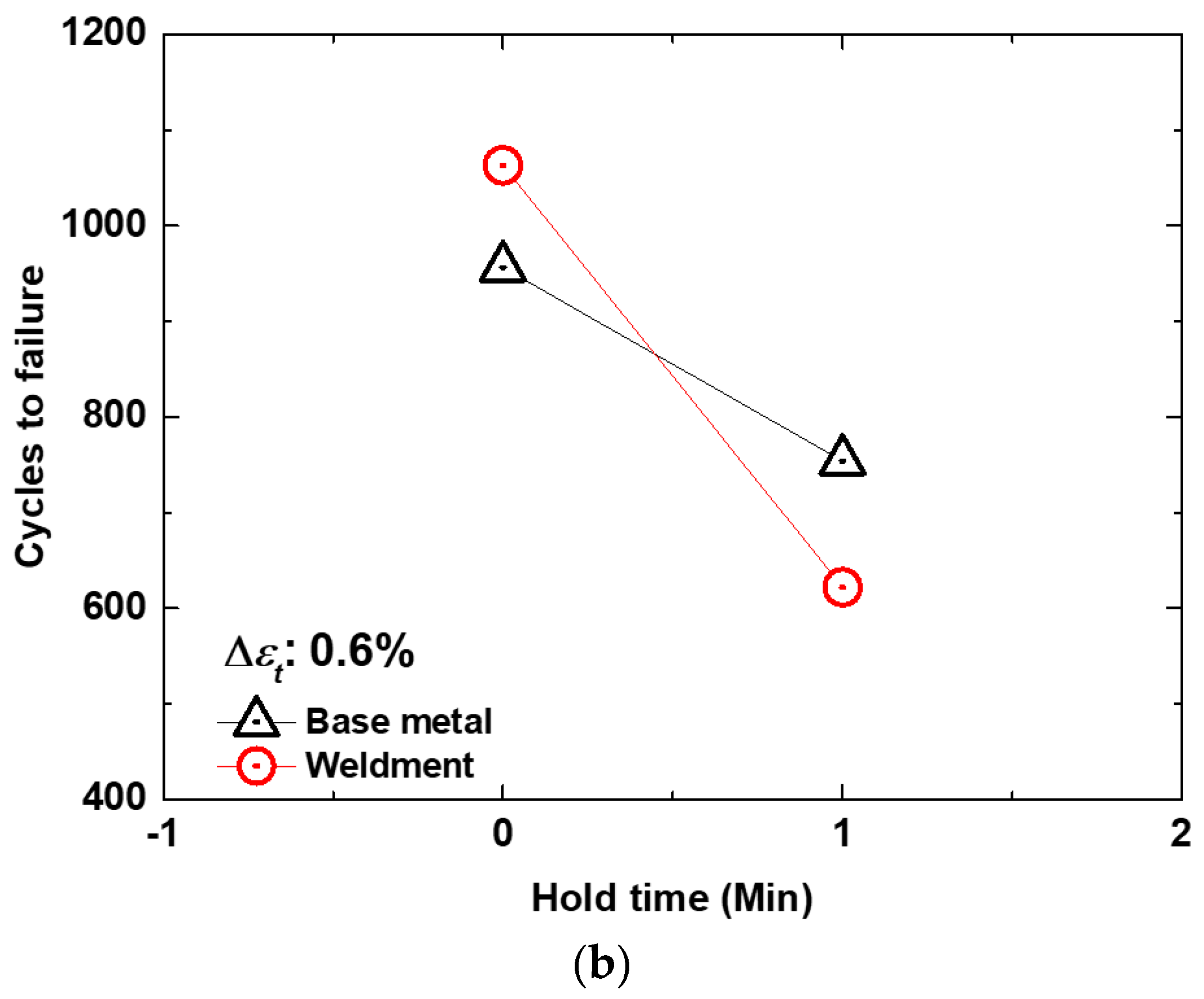
3.3. Influence of Hold-Time

From the LCF life results in Section 3.2, it is found that the addition of HT significantly reduces the LCF life both materials. This finding is similar to the observation for influence of typical waveform in Alloy 800H from the literatures [3,11]. Figure 10 shows the evolution of peak tensile-compressive stresses for BM and weldments due to the addition of HT. From the figure, the addition of HT induces an unequal cyclic stress response for tension and compression when compared with the symmetrical LCF test. For BM specimens, the tension stress is lower than in compression at a saturation phase and is also lower than that of the weldments.
The mid-life cyclic stress–strain hysteresis loops of 0.6% total strain range tested with and without HT for BM and weldments are shown in Figure 11a,b, respectively. From graphs, a drop in maximum stress can be observed during the hold period, indicating a stress relaxation behavior (SRB). Based on the strain range partitioning method, the additional inelastic strain (Δεin) can be seen for the HT test, indicating the attribution of creep mechanisms [11]. This inelastic strain is considered to be time-dependent. It is believed that the elastic strain was transformed into the extra plastic deformation during the HT. The SRB during maximum tensile HT at a stable cycle for BM and weldments are plotted in Figure 12. From the figure, the stress is exponentially relaxed in a similar behavior with times. During the test, the initial sudden drop decreased to 50% of the initial stress point, followed by a slight stress drop after 5 s. From the curves, however, the minimum stress level of BM is lower compared with that of the weldments. It is indicated that the BM sustained more creep damage than the weldments. As the stress was exponentially changed during the relaxation period, a constitutive equation is necessary to describe the stress relaxation behavior. This stress relaxation curve can be used to determine the state of stress for the creep phenomenon through the power-law at a certain time as follows:
  σ c f = m ( Δ t ) n  
where σcf (MPa) is stress state during HT, m and n are regarded as fitting parameters, and Δt is known as the time during the HT in seconds. In order to quantify the creep damage accounted for during the HT, the collected creep rupture data from several temperature ranges is needed to accommodate fitting parameters (based on the Larson–Miller relationship) for the calculation of rupture time corresponding to the varying stress levels. However, the creep and creep-fatigue tests are now still in progress to provide the correlation between the creep rupture time, temperature, and applied stress; thus, it can be considered for further investigations.

3.4. Fracture Micrographs

Figure 13a–d shows typical SEM images for LCF crack initiation and propagation of BM and weldments tested at 0.6% total strain range. In the LCF test, the crack initiation and propagation for both materials occurred in a classical transgranular fracture mode. The fracture analysis show that both materials display mixed ductile/brittle fracture with the presence cleavages and dimples in the final fracture area. Typical cleavage-like facets and striations can be observed in the initiation and propagation zones, as shown in Figure 13b,d. From the figures, the presence of more brittle fracture can be observed for weldments, with the predominance of large cleavage-facets rather than the BM specimens. These observations are supported by the result of the intense plastic deformation of the BM. LCF cracking for weldments is located in the weld metal rather than in the HAZ. It is proven that the microstructural heterogeneity was incapable of accommodating the deformation during LCF testing, in which the weld metal has lower microhardness than the HAZ. From the figure, there is remarkable evidence of an oxidation layer covering the surface and striations, indicating that the crack initiation occurred from both oxidation and stress concentration. The results show that the oxide-enhanced transgranular crack growth occurred from the oxide layer at the crack tip. The oxidation layer formed a brittle thin layer and assisted in the crack propagation. It is well known from the literature [5] that DSA induced the pinning effect and higher stress response, and thus led to the stress concentration and inhomogeneous deformation at the GBs, which restricted the dislocation movement. In this study, however, the DSA did not stimulate the unique fracture characteristic as it only appeared during the initial cycles.
Figure 14 shows typical SEM images for the LCF test with HT for both BM and weldments. From the figures, it is observed that the introduction of HT promotes a transition to intergranular fracture (shown by white arrows). This mixed-mode propagation fracture mode has also been reported in literatures [6,11] to cause an acceleration in cracking. We believe that the transition to intergranular crack was attributed primarily to the creep mechanisms during HT. It was reported from literature [6] that the creep, fatigue, oxidation, and precipitation mechanisms operated concurrently. In this case, the fatigue life was severely affected by the combined effect of all of them, although there has been no outward appearance of large creep cavities. These observations indicate that the fatigue life was determined by the combination of the oxidation and effective inelastic strain due to the stress relaxation, by means of the creep recovery process of dislocation during HT. It is already mentioned that the damaging effects of oxidation also assisted the intergranular cracking. Many of the surface cracks were initiated by the rupture of oxide scales formed at the surface-connected GBs. Figure 15 illustrates a typical surface-connected GB oxide crack for the BM specimen. The oxide layer was expected to form as a protective layer to reduce the oxidation rates from Cr ion. As the Alloy 800H is an iron–nickel base superalloy, the EDS measured compositions show a high Fe and Cr contents, suggesting the formation of the outer oxide layer FeCr2O4. The deeper oxide layer of (Cr)2O3 has also been observed in the matrix as the crack developed just beneath the outer oxide layer. Observations with EDS supported this by a higher Cr content. The following point can be identified as the high Fe and Cr contents measured from the crack tip area, suggesting that a Cr-depleted zone (oxide formation) developed by a reaction from carbide precipitates. An oxide surface-connected precipitates crack occurred because the intergranular precipitates reacted with the oxygen ions during high temperature exposure and easily diffused with the Cr-depleted zone. These observations are identical to what has been reported in the literature [12]. When the oxide outer layer formed and connected to the oxidized intergranular precipitates, the cohesive force weakened and initiated the crack. The oxidation at the crack tip rendered a more brittle and a lower fracture toughness thin layer than the matrix, which assisted crack initiation and propagation.
The fractured specimens showed a great amount of intergranular precipitation. Figure 16 shows morphology of precipitates distribution for BM and weldments, respectively. Based on EDS results, the intergranular precipitates contain high Fe, Ni, and Cr contents, however, the precipitates oxide formed is in the form of (Cr)M23C6 and primary cuboidal carbide is identified as Ti(C,N). This Alloy 800H contains 0.54% titanium and 0.07% carbon, and hence formed titanium carbide and titanium carbonitride due to the high temperature environment. According to the EDS results, the majority of precipitates in weldments contain high contents of Ni, Cr, and O, indicating the formation of Cr23C6 particles. These carbides are well known to provide a coherency strengthening to the matrix and enhance the fracture toughness [8]. M23C6 precipitates are found to interact with dislocations and inhibition of intergranular crack; such typical creep large cavities were not found in this study [11].

4. Conclusions

The LCF behaviors of Alloy 800H BM and its weldments were investigated by means of experimental tests for use in the VHTR nuclear system. To provide Section-III fatigue design curves of the ASME Code data, a series of fully reversed LCF tests were performed with total strain ranges of 0.6%, 0.9%, 1.2%, and 1.5% at 700 °C. The following key conclusions can be drawn:
(1)
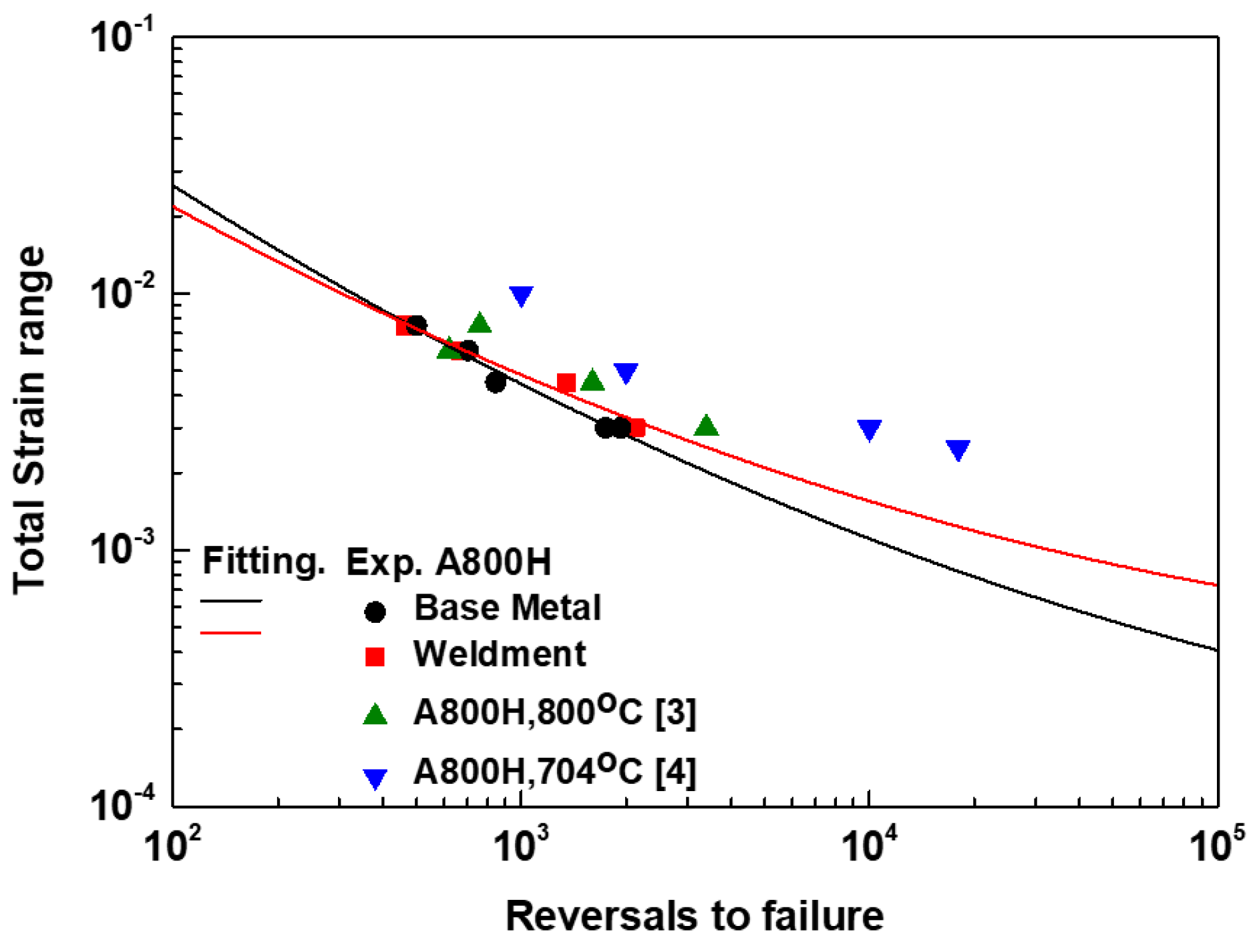
The LCF life of the BM and weldments was found to be comparable, indicating a good welding technique, and the increase of total strain range reduced the LCF life both materials. The fatigue life was strongly reduced by means of additional HT.
(2)
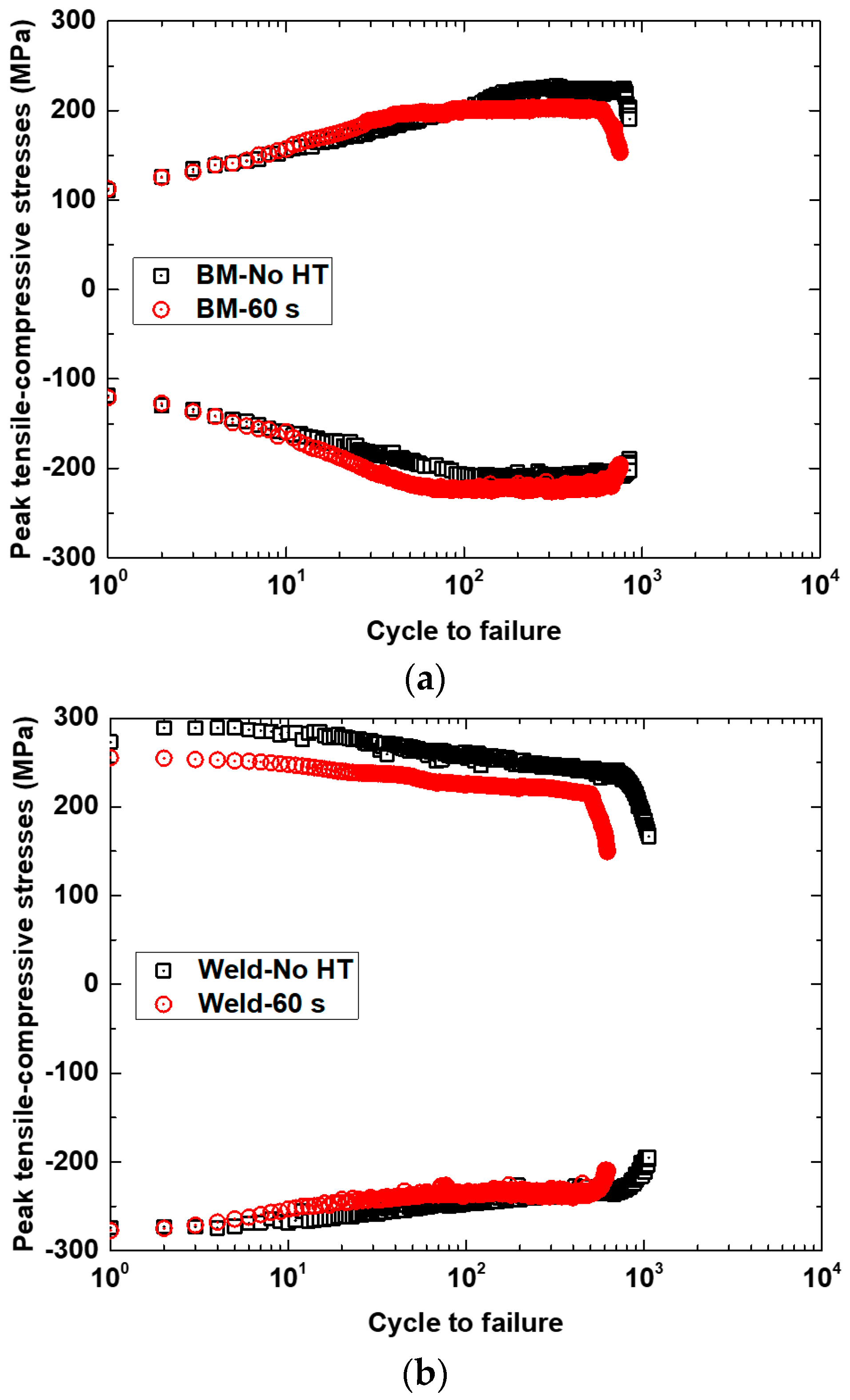
Cyclic stress response behavior varied between both materials. The BM showed an initial cyclic hardening for the first 100 cycles, followed by saturation phase just prior to failure, whereas the weldments were cyclically softened with cycles for the whole life.
(3)
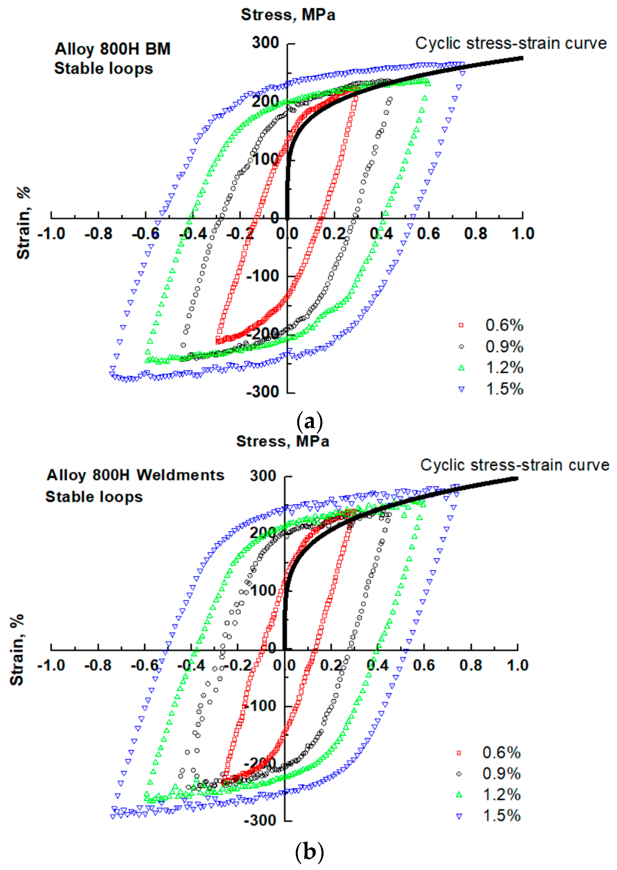
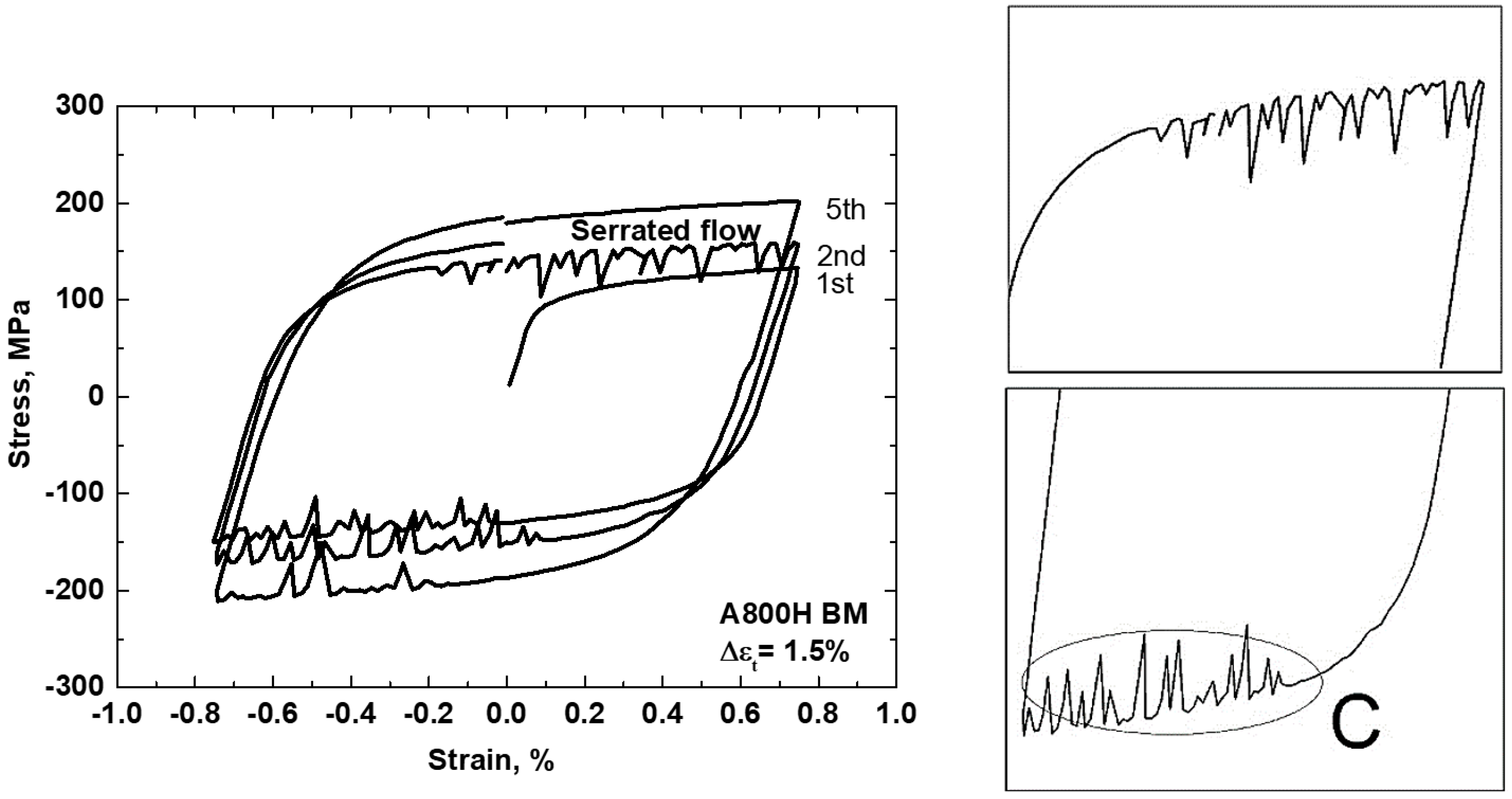
The serrated yielding was observed in the cyclic stress–strain curves for both materials in all tests. These serrations occurred predominantly for BM specimens and disappeared after some cycles. This type of serrated flow stress belongs to Type C according to their characteristic of the dropped stress below the general level of the stress–strain curve.
(4)
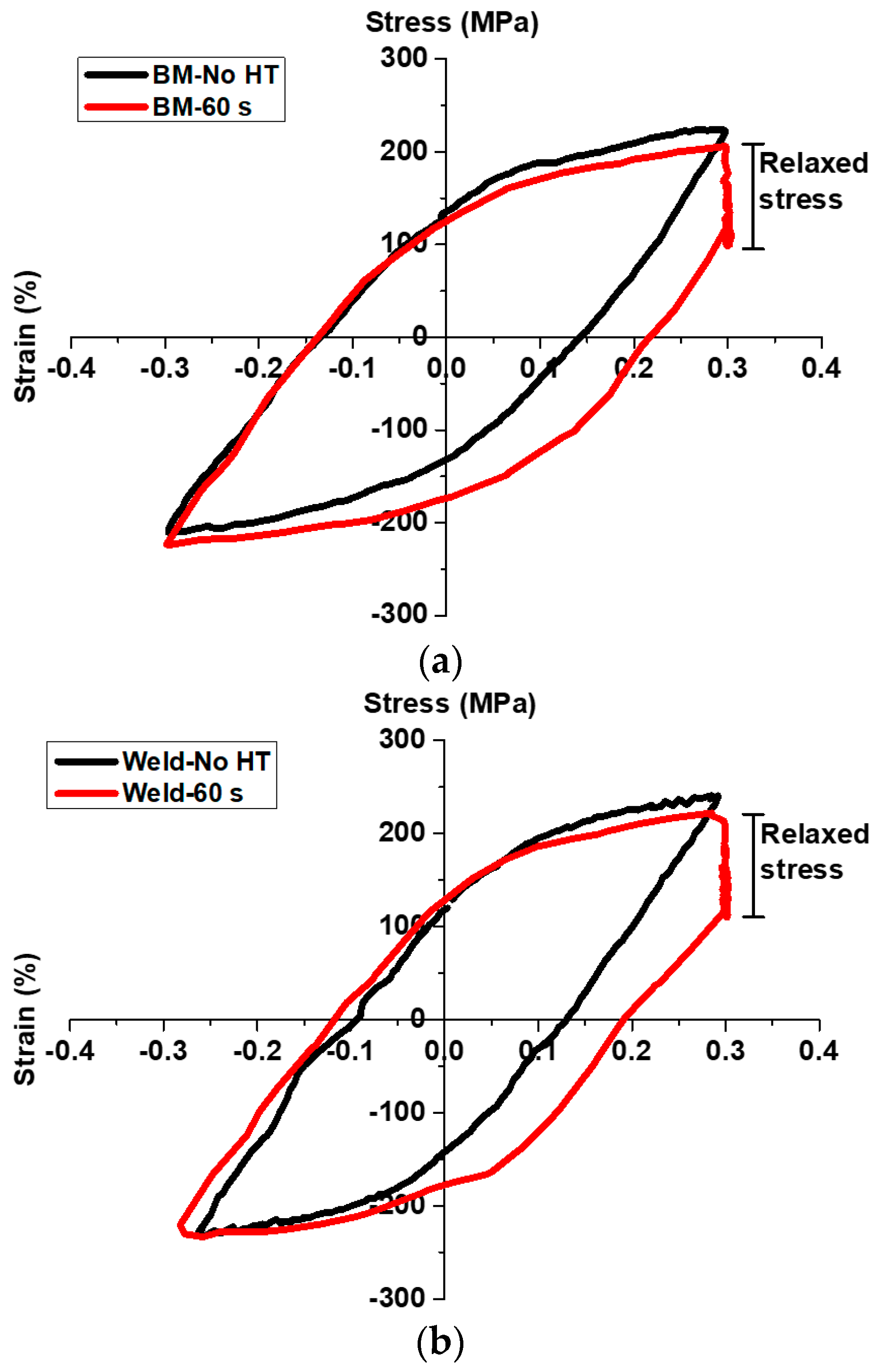
LCF tests with HT induced an unequal cyclic stress response, and thus a visible lower peak tensile stress rather than the compressive stress. During the HT, the effective inelastic strain was promoted by the SRB, which suggests the creep recovery process of dislocation.
(5)
The fracture mechanism depended on the type of material and waveform. The fracture analysis show that both materials display mixed ductile/brittle fracture, although the presence of more brittle fracture can be observed for weldments. In LCF tests, the crack initiation and propagation for both materials occurred in a classical transgranular fracture mode. The introduction of HT caused a transition to intergranular cracks (mixed-mode fracture mode). The fatigue life and fracture mechanisms were severely influenced by the fatigue, oxidation, and M23C6 precipitates. In LCF tests, the oxide-enhanced transgranular fracture dominated crack growth. The damage between the time-dependent creep, fatigue, and oxidation occurred synergistically in LCF tests with HT.
Based on the results of this work, in future research, some actual investigation regarding the environmental effects (such as the reactivity of helium environment on microstructure and mechanical properties, the high reactivity of hydrogen will assist the crack formation, thus compromising its material performance under fatigue loads, and elevating the temperature to the critical limit) will be very valuable for the development of appropriate fatigue design margins in VHTR environments.

Author Contributions

This research project was supervised by S.-J.K. S.-J.K. and R.T.D. constructed and performed the experimental works. R.T.D. wrote the original draft preparation. All authors contributed to the review and editing of this manuscript. W.-G.K. and E.-S.K. were involved in funding acquisition of this project.

Funding

This research and APC were supported by Nuclear Research & Development Program of the National Research Foundation of Korea (NRF) and funded by the Ministry of Science, ICT, & Future Planning through Korea Atomic Energy Research Institute (KAERI), Grant code: NRF-2017M2A8A1019392.

Conflicts of Interest

The authors declare no conflict of interest.

References

  1. Ren, W.; Swindeman, R. A review of Alloy 800H for applications in the Gen IV nuclear energy systems. In Proceedings of the 2010 ASME Pressure Vessels and Piping Division Conference, Bellevue, WA, USA, 18–22 July 2010. [Google Scholar]
  2. Kim, W.G. Mechanical Property and Its Composition of Superalloys for High Temperature Gas Cooled Reactor; Korea Atomic Energy Research Institute (KAERI): Daejeon, Korea, 2005. [Google Scholar]
  3. Kolluri, M.; ten Pierick, P.; Bakker, T. Characterization of high temperature tensile and creep-fatigue properties of Alloy 800H for intermediate heat exchanger components of (V)HTRs. Nucl. Eng. Des. 2015, 284, 38–49. [Google Scholar] [CrossRef]
  4. Kaae, J.L. High-temperature low-cycle fatigue of Alloy 800H. Int. J. Fatigue 2009, 31, 332–340. [Google Scholar] [CrossRef]
  5. Rao, K.B.S.; Schiffers, H.; Schuster, H.; Halford, G.R. Temperature and strain-rate effects on low-cycle fatigue behavior of Alloy 800H. Metall. Mater. Trans. A 1996, 27A, 255–267. [Google Scholar] [CrossRef]
  6. Rao, K.B.S.; Schuster, H.; Halford, G.R. Mechanisms of high-temperature fatigue failure in Alloy 800H. Metall. Mater. Trans. A 1996, 27A, 851–861. [Google Scholar] [CrossRef]
  7. Sonoya, K.; Tomisawa, Y. Cracking by elevated temperature embrittlement in the HAZ of alloy 800H. Weld. Int. 1991, 5, 425–429. [Google Scholar] [CrossRef]
  8. Sayiram, G.; Arivazhagan, N. Microstructural characterization of dissimilar welds between Incoloy 800H and 321 Austenitic Stainless Steel. Mater. Charact. 2015, 102, 180–188. [Google Scholar] [CrossRef]
  9. Moss, T.E.; Was, G.S. Dynamic strain aging of nickel-base Alloy 800H and 690. Metall. Mater. Trans. A 2012, 43A, 3428–3432. [Google Scholar] [CrossRef]
  10. Rodriguez, P. Serrated plastic flow. Bull. Mater. Sci. 1984, 6, 653–663. [Google Scholar] [CrossRef]
  11. Nilsson, J.O.; Sandström, R. Influence of temperature and microstructure on creep-fatigue of Alloy 800H. High Temp. Technol. 1988, 6, 181–186. [Google Scholar] [CrossRef]
  12. Chen, W.S.; Kai, W.; Tsay, L.W.; Kai, J.J. The oxidation behavior of three different zones of welded Incoloy 800H alloy. Nucl. Eng. Des. 2014, 272, 92–98. [Google Scholar] [CrossRef]
Figure 1. (a) Configuration of the weldments plate; (b) shape and dimension (unit: mm) of cylindrical low-cycle fatigue (LCF) specimen.
Metals 08 00918 g001
Figure 2. Optical micrographs of (a) base metal (BM); (b) weld; and (c) heat affected zone (HAZ).
Metals 08 00918 g002
Figure 3. Microhardness results of the Alloy 800H weldment.
Metals 08 00918 g003
Figure 4. (a) LCF life graphs as a function of total strain range; (b) influence of hold-time (HT) on LCF life of Alloy 800H BM and weldments.
Metals 08 00918 g004aMetals 08 00918 g004b
Figure 5. The peak tensile-compressive stresses for Alloy 800H: (a) BM and (b) weldments.
Metals 08 00918 g005
Figure 6. Comparison of mid-life hysteresis loops for Alloy 800H: (a) BM and (b) weldments.
Metals 08 00918 g006
Figure 7. Typical stress–strain hysteresis loops indicating serrated yielding for BM at 1.5% total strain range with an enlarged view of the first quarter cycle.
Metals 08 00918 g007
Figure 8. The Coffin–Manson–Basquin (CMB) curves of Alloy 800H: (a) BM and (b) weldments.
Metals 08 00918 g008
Figure 9. Comparison of CMB curves of Alloy 800H from the test and other existing data in literatures [3,4].
Metals 08 00918 g009
Figure 10. The evolution of peak tensile-compressive stresses for LCF with and without HT of Alloy 800H: (a) BM and (b) weldments.
Metals 08 00918 g010
Figure 11. The mid-life cyclic stress–strain hysteresis loops for LCF tests with and without HT of Alloy 800H tested at 0.6% total strain range: (a) BM and (b) weldments.
Metals 08 00918 g011
Figure 12. The stress relaxation behavior (SRB) during maximum tensile HT at stable cycle. LCF-HT test at 0.6% total strain range.
Metals 08 00918 g012
Figure 13. Typical scanning electron microscope (SEM) images for LCF crack initiation and propagation tested at 0.6% total strain range: (a) crack initiation, BM; (b) crack propagation, BM; (c) crack initiation, weldments; and (d) crack propagation, weldments.
Metals 08 00918 g013
Figure 14. Typical SEM images for LCF test with HT of Alloy 800H: (a) BM and (b) weldments. The arrows indicate the intergranular crack shown in both pictures.
Metals 08 00918 g014
Figure 15. Typical surface-connected grain boundaries (GBs) oxide crack for BM specimen. LCF-HT test at 0.6% total strain range.
Metals 08 00918 g015
Figure 16. Typical morphology of precipitates distribution of Alloy 800H: (a) BM and (b) weldments. LCF-HT test at 0.6% total strain range.
Metals 08 00918 g016aMetals 08 00918 g016b
Table 1. The chemical composition of Alloy 800H and its filler metal (wt.%).
MaterialCNiFeSiMnCrTiPSAlCu
A800H0.0730.18Bal0.420.9820.430.540.022-0.490.45
KW-T820.0730.18Bal0.420.9820.430.540.022-0.490.45
Table 2. Test matrix of tensile and low-cycle fatigue (LCF) tests performed in this study. BM—base metal.
Test ConditionsLCF TestLCF Test with Hold Time
700 °C700 °C
No. of specimenBM51
Weldments41
Table 3. The Coffin–Manson–Basquin (CMB) constants for Alloy 800H BM and weldments.
Specimen/Cinstantsεfcσf’ (MPa)b
BM2.967−1.0171047.0−0.193
Weldments1.393−0.9021100.5−0.182

