Article

Machining Performance of TiAlN-Coated Cemented Carbide Tools with Chip Groove in Machining Titanium Alloy Ti-6Al-0.6Cr-0.4Fe-0.4Si-0.01B

1
Guangdong Provincial Key Laboratory for Processing and Forming of Advanced Metallic Materials, South China University of Technology, Guangzhou 510640, China
2
The Key Laboratory of High Efficient Near-Net-Shape Forming Technology and Equipments for Metallic Materials, Ministry of Education, China (category B), Guangzhou 510640, China
3
School of Mechanical and Automotive Engineering, South China University of Technology, Guangzhou 510640, China
*
Author to whom correspondence should be addressed.
Metals 2018, 8(10), 850; https://doi.org/10.3390/met8100850
Submission received: 19 September 2018 / Revised: 5 October 2018 / Accepted: 11 October 2018 / Published: 19 October 2018

Abstract

:
In this paper, TiAlN-coated cemented carbide tools with chip groove were used to machine titanium alloy Ti-6Al-0.6Cr-0.4Fe-0.4Si-0.01B under dry conditions in order to investigate the machining performance of this cutting tool. Wear mechanisms of TiAlN-coated cemented carbide tools with chip groove were studied and compared to the uncoated cemented carbide tools (K20) with a scanning electron microscope (SEM) and energy dispersive spectrometer (EDS). The effects of the cutting parameters (cutting speed, feed rate and depth of cut) on tool life and workpiece surface roughness of TiAlN-coated cemented carbide tools with chip groove were studied with a 3D super-depth-of-field instrument and a surface profile instrument, respectively. The results showed that the TiAlN-coated cemented carbide tools with chip groove were more suitable for machining TC7. The adhesive wear, diffusion wear, crater wear, and stripping occurred during machining, and the large built-up edge formed on the rake face. The optimal cutting parameters of TiAlN-coated cemented carbide tools were acquired. The surface roughness Ra decreased with the increase of the cutting speed, while it increased with the increase of the feed rate.

1. Introduction

Titanium and its alloys have been used widely in many areas, such as aerospace, chemical, biomedical, and automotive industries, due to their outstanding properties [1,2,3,4]. These prominent properties include a high strength-to-weight ratio, strong corrosion resistance, and the ability to retain high strength at high temperature [5,6]. However, titanium alloys are classified as difficult-to-machine materials due to high chemical reactivity, low thermal conductivity, and low modulus of elasticity [7]. Low thermal conductivity leads to considerable heat concentrating at the cutting zone. High chemical reactivity at high temperature causes serious friction and wear at the tool-chip interface. Low elastic modulus results in elastic deformation of the workpiece.
Researchers and engineers have developed various methods and technologies to improve the quality of machining and to extend tool life [8]. As for cutting tools used in machining of titanium alloys, cemented carbide tools are the best compromise of performance and cost currently available [2,9]. Although ultra-hard tools, such as polycrystalline diamond (PCD), have better performance than cemented carbide tools, they are very expensive and they increase the cost of machining. Dry machining reduces the cost of manufacturing and saves the environment by the abandonment of cutting fluid [10,11]. Dry machining is a green manufacturing process and is becoming more and more popular. However, the cutting temperature in dry machining is very high, which leads to short tool life and machined surface damage [12].
The surface coating of the cutting tool serves as a protection layer in machining titanium alloys and supplies lubrication for machining. According to previous studies, the life of uncoated carbide tool is less than 6 min under dry condition, and serious crater wear and adhesive wear occur when machining Ti6Al4V (TC4) [13]. There are several kinds of coating, such as TiAlN, TiCN, CrAlSiN, TiAlSiN, AlMgB14-TiB2 and so on [6,14,15,16,17]. TiAlN coating is one kind of excellent coating and possesses strong chemical stability and good resistance of oxidation wear at 900 °C [18]. Cutting length of TiAlN-coated tools reaches 30 m due to better wear resistance in dry machining of TC4 [14]. The turning of TC4 shows that a TiAlN-coated tool has better wear resistance and chemical stability, and its life is longer than that of (TiCN + Al2O3 + TiN)-coated tools [19]. Long chips can damage the workpiece surface, the operator, machine, and cutting tool. Grooved tools can curl and break the chips into smaller sizes and shapes and have better performance and longer tool life than flat-faced tools [20,21]. It is pointed out that grooved tool drastically alter the tool-chip interfacial tribological conditions and wear patterns of the cutting tool due to configurations of the groove [22]. It is found that the location of the maximum temperature is an area of high tool wear rate [23]. For grooved tools, it is on the secondary face region, and then eventually moves towards other locations on the tool face [21]. It is revealed that cutting force decomposes and distributes in three major tool-wear regions: the edge region, secondary-face region, and groove-backwall region [24]. It is indicated that grooved tools have better performance of chip breaking than flat-faced tools [25]. Thus, it is necessary to study the machining performance of TiAlN-coated cemented carbide tools with chip groove in dry machining Ti-6Al-0.6Cr-0.4Fe-0.4Si-0.01B (TC7).
As a kind of titanium alloy, TC7 has outstanding mechanical properties, such as lower yield strength and higher tensile strength than TC4. Thus, TC7 has better plasticity and strengthen than TC4. TC7 is often used as material for shaft components, which bears great dynamic force, and the machined surface should have low surface roughness. However, like other titanium alloys of α + β phase, TC7 is also a difficult-to-machine material, and there are few published studies about it. TiAlN-coated cemented carbide tools with chip groove are estimated to be suitable for machining titanium alloy in the present study. The novelty of the paper is to study the performance of a TiAlN-coated cemented carbide tool with a chip groove in dry turning TC7. The aim of the paper is to investigate the effects of cutting parameters on tool life and surface roughness and acquire the optimal cutting parameters. The wear mechanisms of TiAlN-coated cemented carbide tools are studied and compared with an uncoated carbide tool (K20) in detail.

2. Experimental Works

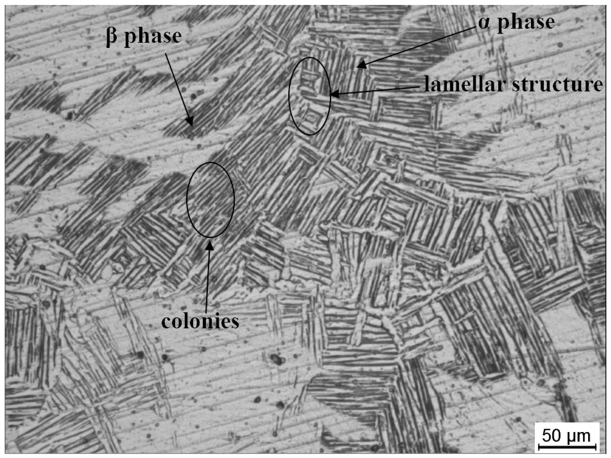
2.1. Workpiece Material
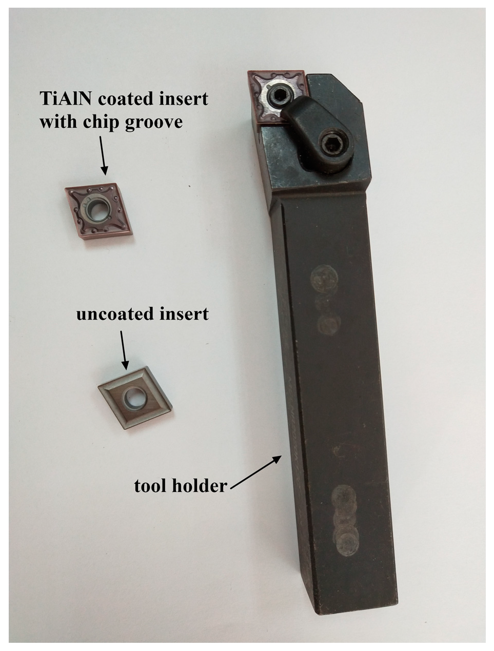
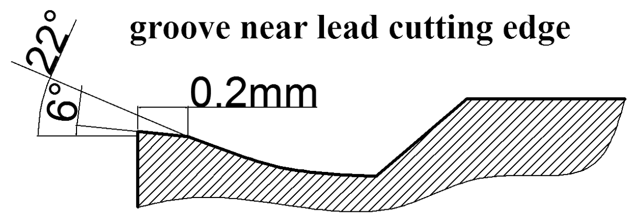
A TC7 round bar with diameter 100 mm and length of 500 mm was used in this study. Its actual chemical composition and mechanical properties are shown in Table 1 and Table 2, respectively. TC7 has better plasticity compared to TC4.
In order to investigate the microstructure of TC7, a cube with side length of 10 mm was cut from the workpiece by electrical discharge machining (EDM). The cube was ground with SiC abrasive paper from 360 to 3000 grit and polished. Then the specimen was etched by Kroll’s reagent (6.5% HF + 15.6% HNO3 + 77.9% H2O) for 10 s to observe the microstructure. The microstructure was observed with a LEICA CTR4000 optical microscope (Leica, Weitzlal, Germany). Its microstructure is shown in Figure 1.

2.2. Cutting Tool

The specification of tool holder was MCLNR2020K12C (ZCCCT Co., LTD, Zhuzhou, China). A TiAlN-coated cemented carbide insert with a chip-groove structure of the type CNMG120404-MA VP 15TF (Mitsubishi Materials, Tokyo, Japan) was used. The substrate material of the insert was ultra-fine grain cemented carbide. TiAlN coating was deposited on the surface of substrate through chemical vapor deposition (CVD). An uncoated carbide insert had a chip-groove structure, and the type was CNMG120404 (K20). It was produced by Mitsubishi Materials (Tokyo, Japan) and the material was UTi20T (WC-Co).
The geometrical parameters of both kinds of inserts fixed in a tool holder are shown in Table 3. The two inserts and tool holder are shown in Figure 2. Figure 3 shows the geometry of the chip groove of the TiAlN-coated insert.

2.3. Machine Tool and Process Strategy

The dry turning experiments were conducted on a CNC CA6150i lathe (DMTG Co., Dalian, China) without lubricant and coolant. A single-factor experiment was conducted, and one test was done for each set. For the same cutting parameter, every insert was taken from the tool holder after the workpiece was machined for 3, 6, 12, 18, and 27 min, respectively. Then the inserts were cleaned in alcohol (99%) ultrasonically for 6 min. The wear morphologies and surface chemical composition of the inserts were characterized with a scanning electron microscope (SEM, Quanta 200 FEG, FEI, Eindhoven, The Netherlands) and energy dispersive spectrometer (EDS), respectively. A VHX-600E-3D (Keyence, Osaka, Japan) super-depth-of-field instrument was used to measure the average flank wear width (VB) of the inserts according to the ISO 3685: 1993 standard. The surface roughness of the machined workpiece was measured with a MarSurf M 300C (Mahr GmbH, Göttingen, Germany) surface profile instrument. For each cutting parameter (for instance, a cutting speed of 60 m/min), six points were tested along the circle of the machined cylindrical surface at equal intervals, then the six values were averaged as one cutting parameters’ surface roughness. Since the cutting temperature in dry machining titanium alloy is high, and tool life is short at high cutting speed, cutting speeds of 40 m/min, 50 m/min, 60 m/min, and 70 m/min were chosen for study in the present paper.

3. Results and Discussion

3.1. Wear Mechanisms of the Tool

Tool wear occurs through the mechanisms of adhesion-dissolution-diffusion during titanium machining [26,27]. High temperature results in adhesion of the workpiece materials on the cutting tool [5]. Elements of the cutting tool and adherent material of the workpiece at the bonding interface can diffuse into each other’s structure [8]. Constituent diffusion induces the decrease of hardness and wear resistance of the tool when tungsten and cobalt diffuse into the workpiece [5,28,29]. There are several wear mechanisms in the present machining: adhesive wear, diffusion wear, stripping, and crater wear. It should be noted that the built-up edge with large size occurs during machining of titanium alloy TC7 as well.

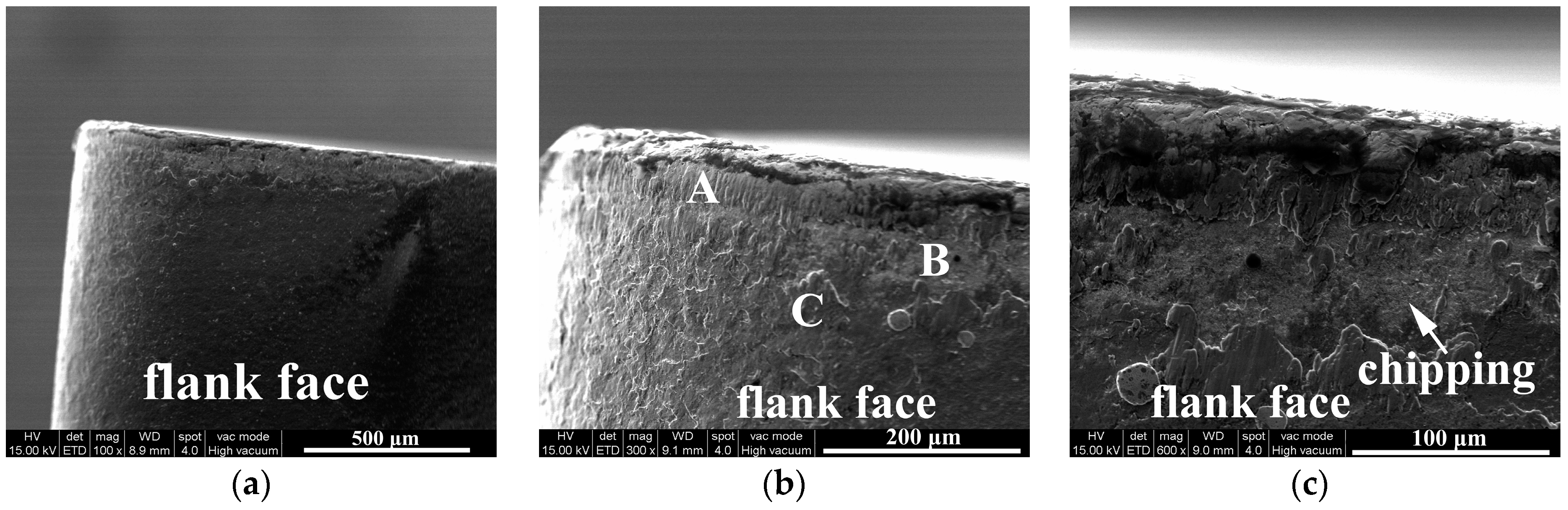
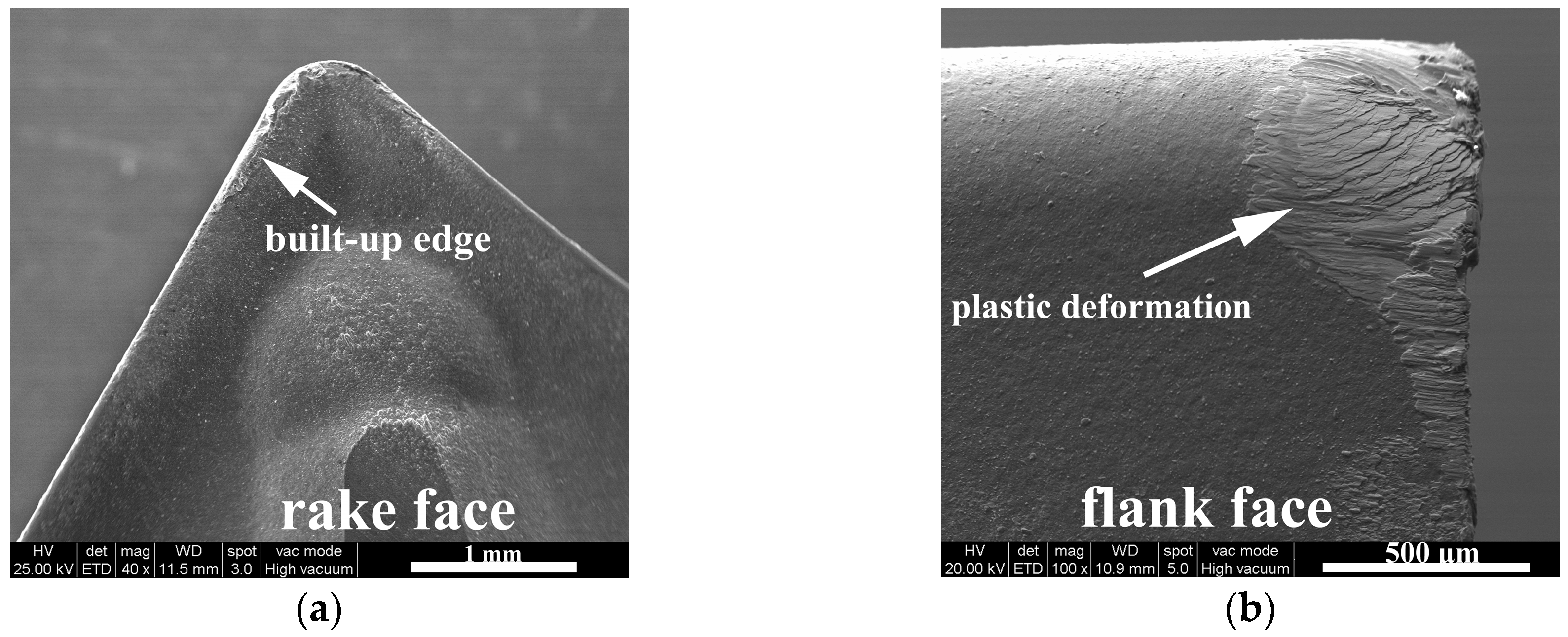
3.1.1. Flank Face Wear

Figure 4 shows the SEM photographs of the worn flank face after machining for 6 min. A uniform wear band occurs obviously on the flank face, which is adhesive wear and delamination. Figure 5 shows the chemical composition of the selected point A, B, and C in the Figure 4b. There is a great deal of Ti element on point A and C, which demonstrates that adhesion and adhesive wear has taken place. In the machining process, high cutting temperature and cutting pressure happen at the cutting zone due to low thermal conductivity of titanium alloys and close contact between the workpiece and cutting tool, which is about 750–800 °C and 1–1.5 GPa [18,30]. High temperature causes the material of workpiece to adhere to the tool surface [26].
The point B contains 55.3 wt.% tungsten and 5.3 wt.% cobalt approximately, which shows that the substrate of the insert has been exposed. As shown in Figure 4b, chipping (stripping) caused by peeling of the adhered workpiece material layer dominates on the flank wear band. This phenomenon can be observed obviously in Figure 4c. The high chemical reactivity, close contact, and high contact pressure of the tool/workpiece interfaces lead to the formation of the adhered workpiece materials layer [7,19,31]. It is observed that about 26.3 wt.% titanium exists on point B, which is the evidence that elements of the workpiece material (Ti, Al, and so on) diffuse into the cutting tool (W, Co, and C), and vice versa. It is reported that the high temperature and the intimate contact in the interface of the tool-fresh chip provides an ideal environment for diffusion. The diffusion of Co from the tool weakens the tool strength and induces the failure of the tool, such as stripping, chipping, and so on [18,29].
As shown in Figure 6, serious plastic deformation takes place on the flank face when cutting speed increases to 70 m/min, meaning the tool fails rapidly. Although the TiAlN coating has excellent high resistance to diffusion wear, superior oxidation wear resistance, and high hot hardness, the yield stress of the tool reduces due to the extraordinary high compressive stress at region of tool nose, and plastic deformation of cutting tool takes place [29,32]. In the present study, high cutting temperature and high compressive stress cause serious plastic deformation of tools.
Figure 7 shows the SEM photographs of the worn flank face of the uncoated insert (K20) after machining. Like other titanium alloys, such as TC4, TC7 has strong chemical affinity at high cutting temperature, so the adhesion of the workpiece material is observed on the flank face [33]. The adhesion is uniform on the flank. With the increase of the cutting speed and cutting time, the adhesion still exists, as shown in Figure 7c, which indicates stronger bonding force between the workpiece material and the cutting tool compared to the machining of TC4. During machining of TC4 with uncoated carbide tools, the adherent layer is removed with the increase of the cutting speed [5].

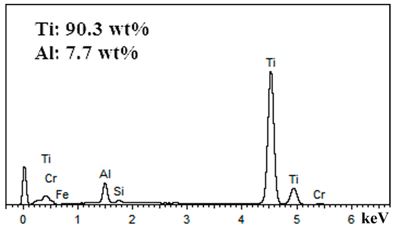
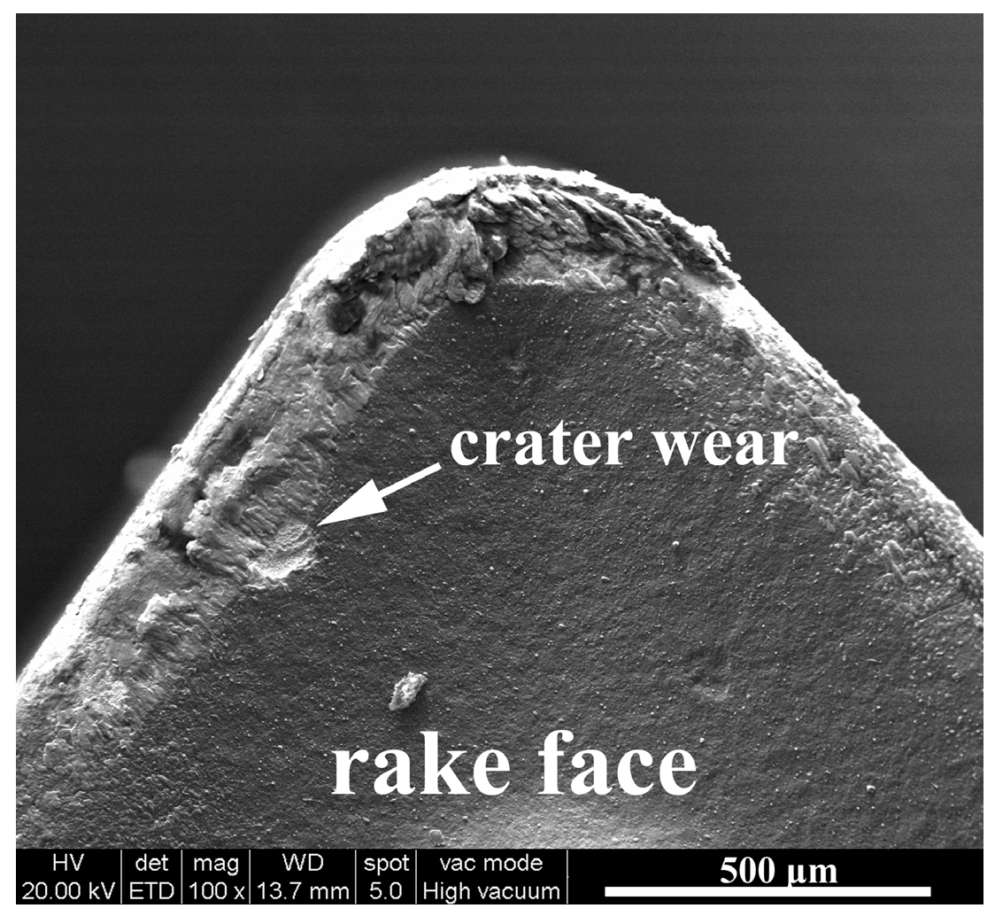
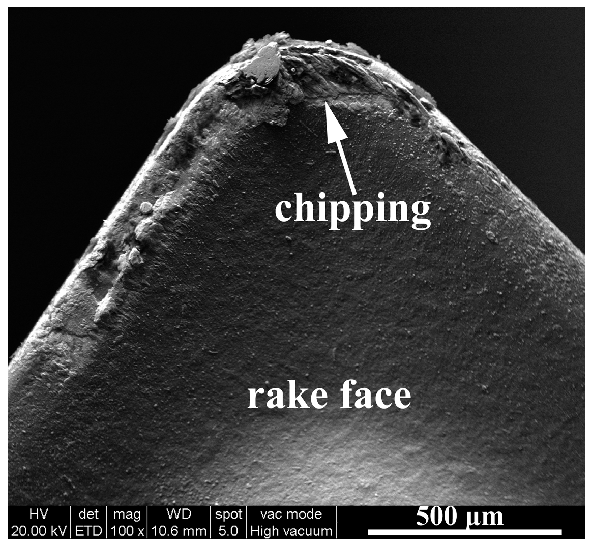
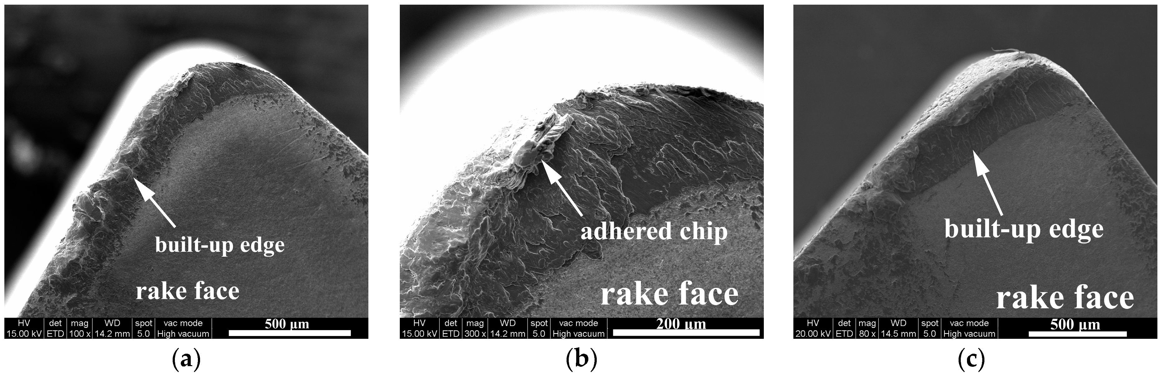
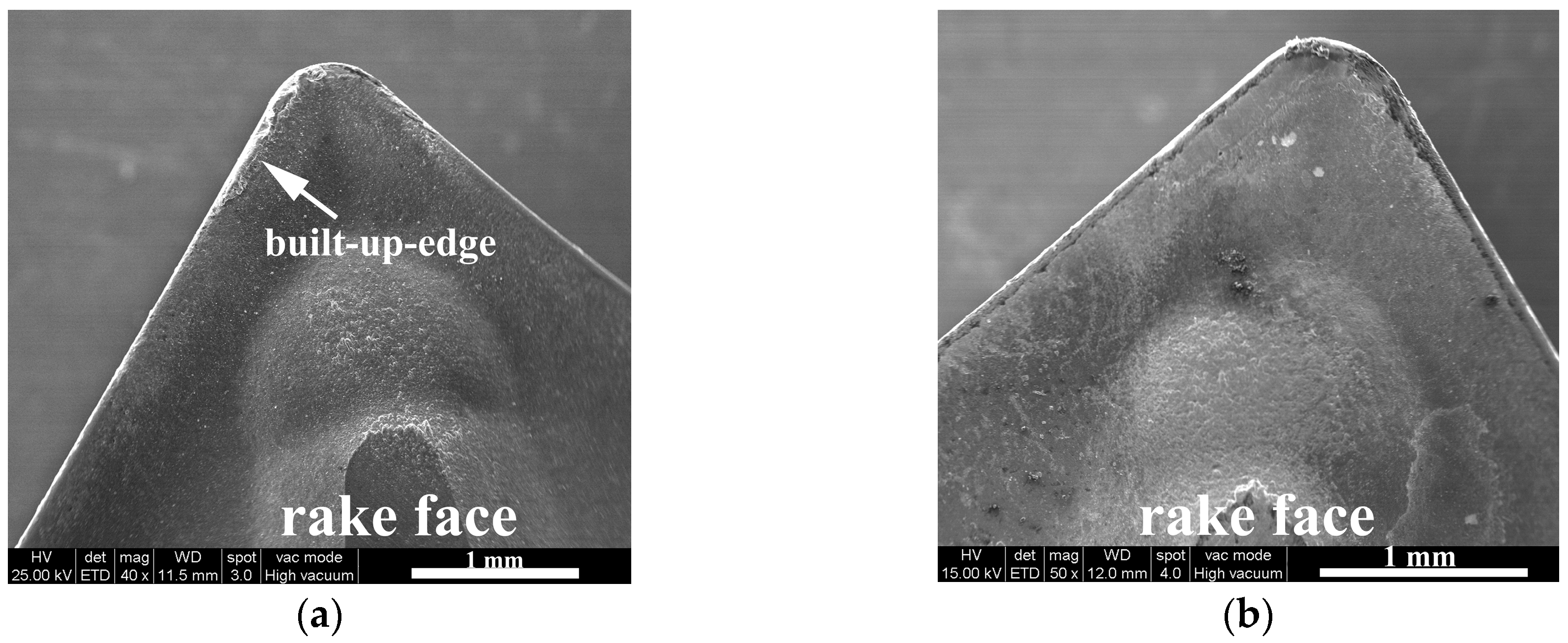
3.1.2. Rake Face Wear

When cutting speed and time reach 50 m/min and 6 min, respectively, a serious adherent layer of the workpiece, namely a built-up edge (BUE) parallel to the cutting edge, forms on the rake face, which can be seen clearly in Figure 8. Strong affinity of TC4 at high cutting temperature is thought to be the principal reason that results in built-up edge formation on the cutting edge [14,34]. Figure 9 shows the chemical composition of the selected point A in Figure 8. About 90.3 wt.% titanium exists at point A, which proves that the material of workpiece adheres to the rake face.
The BUE can protect the cutting edge with adherent material of the workpiece [35]. It can also protect the tool substrate from abrasive wear or avoid formation of a crater near the cutting edge [7,36]. However, the BUE is a dynamic structure, meaning its shape and size change all the time [5,37]. If the cutting speed becomes higher, the cutting forces raises, or the cutting temperature becomes lower, this protective layer will be removed or its size will reduce, which results in failure of the cutting edge, or causes adhesive wear, or increases tool wear, chipping, fracture, or coating peel-off [37,38,39]. The size and shape of BUE shrinks due to enhancement of the cutting speed, which can be seen from Figure 10 and, especially, from Figure 11, it is proved from the discontinuous shape of BUE due to peeling.
The crater wear forms on the rake face, as presented in Figure 10. The tight metal-to-metal friction and high temperature provide an ideal environment for diffusion of tool material elements across the tool/workpiece interface and result in the transport of tool materials into the adherent layer of the chip [33,40]. The elements of tungsten and carbon from WC and cobalt from the binder phase are carried away by the chip flow. Materials of the workpiece diffuse into the surface layer of the tool or react with it, which weakens the hardness and wear resistance of the cutting tool [9,37,41]. The diffusion leads to the crater wear, especially under conditions of longer cutting time or higher cutting speed [27,33]. With increasing time, the crater becomes deeper and deeper, and even the substrate is exposed, which can be seen in Figure 10 and Figure 11.
As shown in Figure 11, chipping (flaking) on the tool nose is observed. It is reported that chipping (flaking) is likely caused by a combination of high thermo-mechanical and cyclic stresses during dry machining [15]. In this paper, the tool nose withstands great thermo-mechanical and cyclic stresses, which causes the adherent materials and surface of the tools to flake. As a result, chipping occurs, and the substrate of the tool is exposed.
As shown in Figure 12, severe BUE takes place on the rake face of K20 inserts; even the chip adheres on the rake face. The reason can be similar to the BUE on the TiAlN-coated insert. However, the BUE on K20 inserts has not been removed at the higher cutting speed of 60 m/min, which reveals that it is more stable than that on TiAlN-coated inserts. This may be attributable to the disparity of the thermal expansion coefficients between tool coating and the substrate, the better lubrication effect, and lower wear value of the TiAlN coating [19,34].
Although the BUE of K20 inserts does not crack at higher cutting speed of 60 m/min, the VB of K20 exceeds 0.3 mm and burrs occur on the edge between the machined surface and unmachined surface. This means the K20 inserts fail. In the following study, we focus on TiAlN-coated inserts.

3.2. Influence of Cutting Parameters on Tool Life of TiAlN-Coated Cemented Carbide Tools

In general, tool life is affected by a great number of factors, such as the machine tool, workpiece material, material and geometry of the cutting tool, cutting parameters, machining conditions, and so on [42]. In the present article, the effects of cutting parameters on tool life are investigated in detail.
When determining the influence of cutting parameters on the tool life, attention should be paid to the ISO tool life testing standard. In the standard, it is specified that VBmax (the maximum flank wear) and VB (average flank wear) is equal to 0.6 mm and 0.3 mm, respectively, at the end of useful tool life. In the present study, VB = 0.3 mm (average flank wear) was chosen as the criterion for the end of tool life [35].

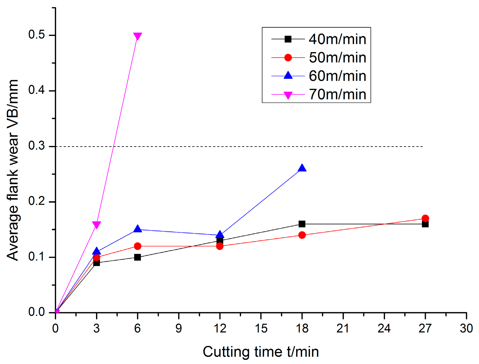
3.2.1. Influence of Cutting Speed

Figure 13 shows the average flank wear against cutting time at different cutting speeds. It can be seen that VB increases rapidly in the initial 3 min, but then rises at a substantially lower slope. The wear curve normally consists of three obvious parts in light of tool wear against cutting time: the initial wear period, steady wear stage, and accelerated wear stage [42]. The initial 3 min is the initial wear period in the present machining in which flank wear rises quickly. For lower cutting speeds of 40, 50, and 60 m/min, the flank wear stays steady after the initial 3 min, meaning tool wear is at the steady wear stage. For the cutting speed of 70 m/min, the VB increases so sharply that the cutting tool fails before 4.5 min. As mentioned above, a built-up edge forms on the rake face at lower cutting speeds, such as 40, 50, and 60 m/min, which protects the cutting tool edge and hinders the formation of craters near the cutting edge [35,36]. Thus, the wear of the tool drastically reduces. However, because the increase of the cutting speed leads to the peeling of the built-up edge, the VB increases greatly at the cutting speed of 60 m/min after 12 min [43]. When the cutting speed reaches 70 m/min, the cutting temperature increases and plastic deformation occurs, which causes the tool to lose its function before 4.5 min, approximately.

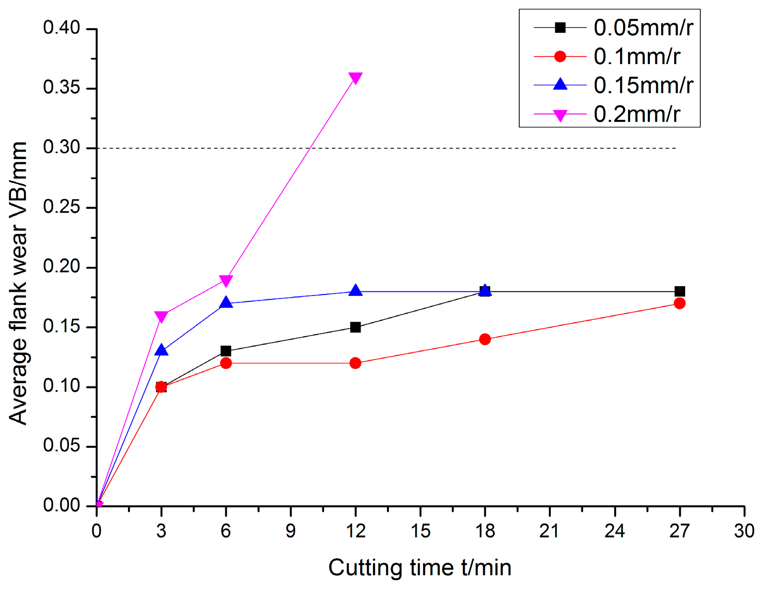
3.2.2. Influence of Feed Rate

Figure 14 shows the progression of VB versus cutting time under different feed rates. The width of the average flank wear band increases with the increase of the feed rate. For lower feed rates, such as 0.05, 0.1, and 0.15 mm/r, VB increases slowly after 3 min. However, for a higher feed rate of 0.2 mm/r, VB increases quickly reaching 0.3 mm. Severe plastic deformation occurs on the tool nose at a feed rate of 0.2 mm/r for 12 min approximately, which is clearly demonstrated in Figure 15. Jawaid et al. [44] studied tool wear characteristics during turning titanium alloy Ti-6246 and revealed that a significant decrease of the tool life at higher feed rates could be ascribed to high temperature and plastic deformation that weakened the cutting tool.
It can be seen from Figure 16 that almost no wear takes place on the tool at a feed rate of 0.15 mm/r, while a more severe built-up edge appears at a feed rate of 0.05 mm/r. It was reported by Wanigarathne et al. [21] that the chip-groove configuration was fully utilized at higher feed rates, suggesting more ‘contact’ between the chip and the secondary face and backwall. It may be concluded that there exists slight contact between the chip flow and chip-groove at lower feed rate, while more of that exists at higher feed rates. The chip-groove is taken full advantage of to reduce temperature, cutting force, and the wear of the tool, which may clarify why the value of VB is smaller at a feed rate of 0.1 mm/r than at a feed rate of 0.05 mm/r.

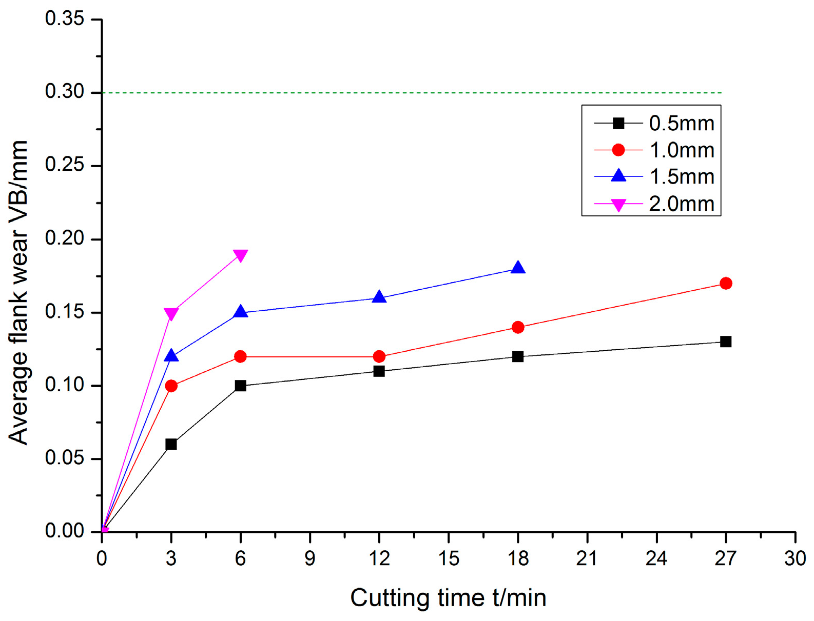
3.2.3. Influence of the Depth of Cut

Figure 17 shows the progression of VB versus cutting time under different depths of cut. The average flank wear band width rises slowly with the increasing depth of cut. Astakhov [45] indicated that the depth of cut had little influence on the tool wear rate. Ee et al. [46] pointed out that less side-flow occurred and more utilization of the chip groove was obtained at a large depth of cut, revealing that the groove backwall was more effective in blocking the chip and shared some of the forces that were acting on the rake face. This explains why flank wear rises slowly when depth of cut increases.

3.3. Influence of Cutting Parameters on Surface Roughness with TiAlN-Coated Cemented Carbide Tools

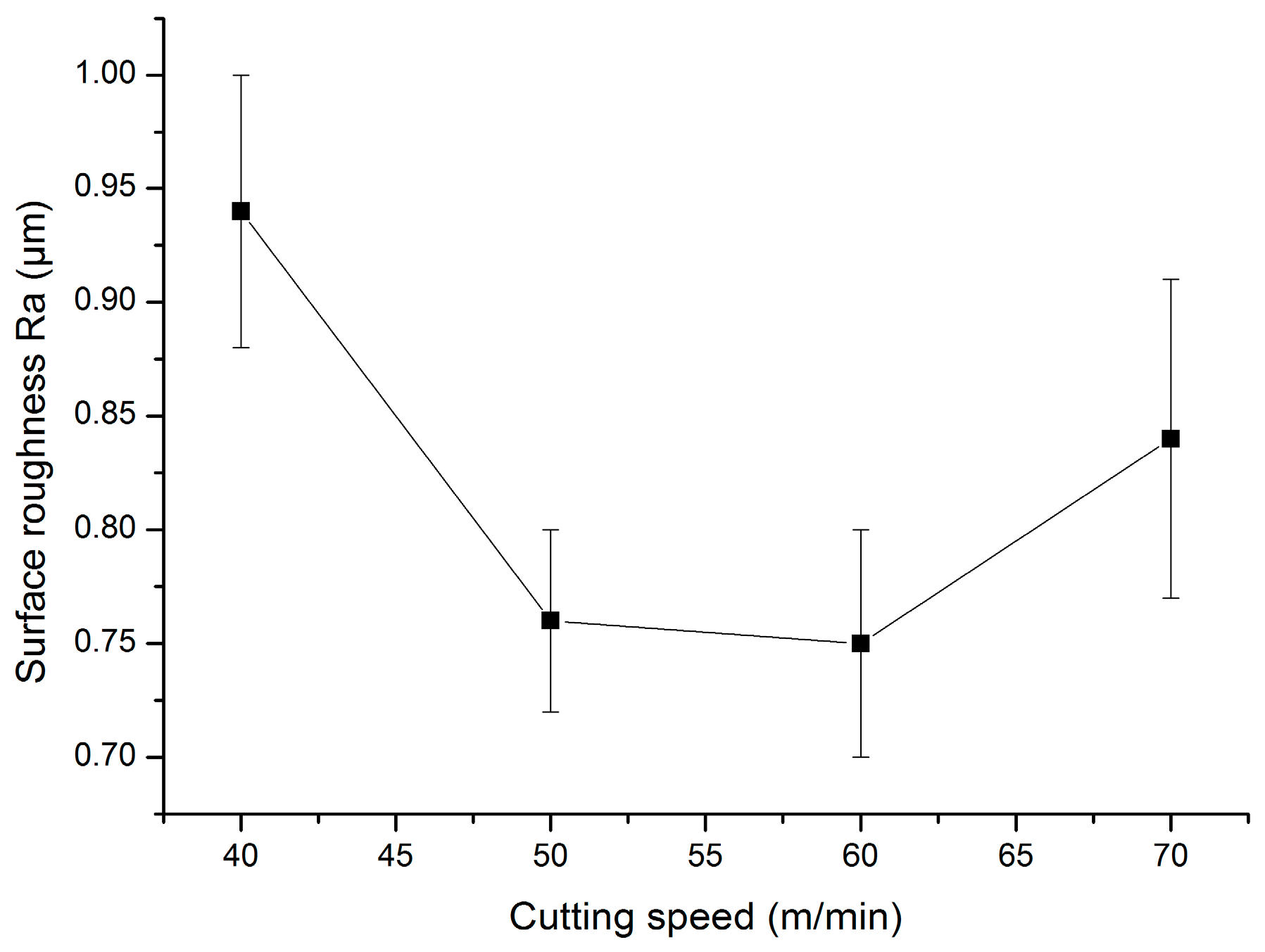
3.3.1. Influence of Cutting Speed

Figure 18 shows the evolution of surface roughness against cutting time at different cutting speeds. The surface roughness decreases with increasing cutting speeds. Raza et al. [47] investigated surface roughness when turning TC4 under several types of conditions and suggested that Ra decreased with increasing cutting speed. For lower cutting speeds, the materials of the workpiece are prone to adhere to the tool, and even a built-up edge occurs. However, the adherent material reduces at higher cutting speeds. In addition, higher cutting speeds soften the surface layer of the workpiece. The combination of these factors makes the surface roughness drop [48,49,50].

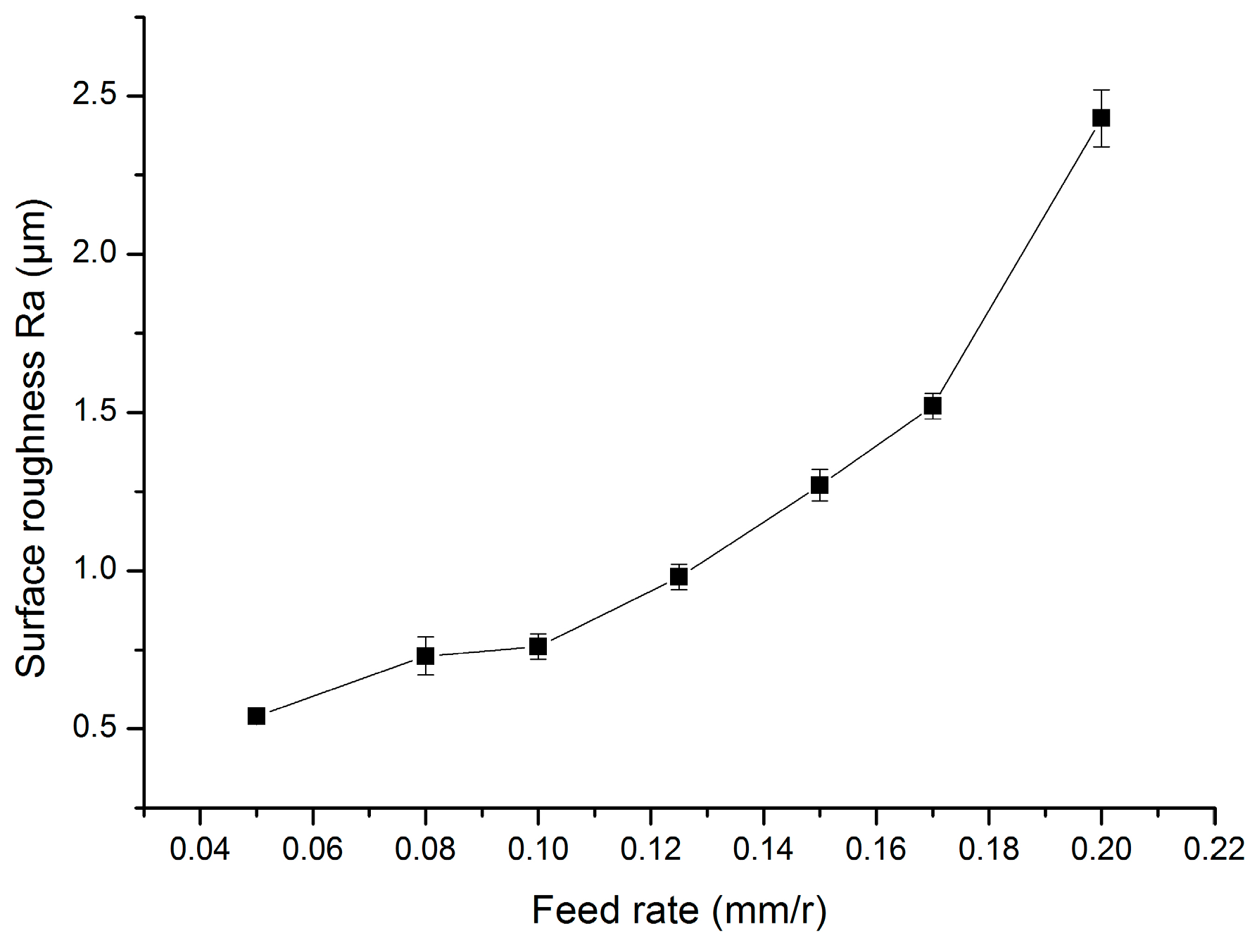
3.3.2. Influence of the Feed Rate

Figure 19 shows the evolution of surface roughness against feed rates. The surface roughness increases quickly with increasing feed rates. Many studies show that the feed rate is the most significant parameter for surface roughness, and the depth of cut has little effect for surface roughness [48,49]. With the increase of the feed rate, the extremely high contact length and contact pressure between the tool and workpiece cause wear of the tool nose to increase quickly. The wear of the tool nose deteriorates the surface roughness [22,32]. Thus, surface roughness increases with the increase of the feed rate.
Although surface roughness increases with the increase of the feed rate, the chip-breaking is improved. As shown in Figure 20, it is evident that the chip is long and continuous at lower feed rates of 0.05 mm/r and 0.1 mm/r, but it is short and segmented at higher feed rates of 0.15 mm/r and 0.2 mm/r. It was reported by Jawahir et al. [22] that a higher feed rate forced the chip to keep in contact with a larger section of the rake face and groove face (inner face) and consequently caused the chip to curl with a small radius. As a result, the chip breaks with a small radius, which improves the condition of the cutting.

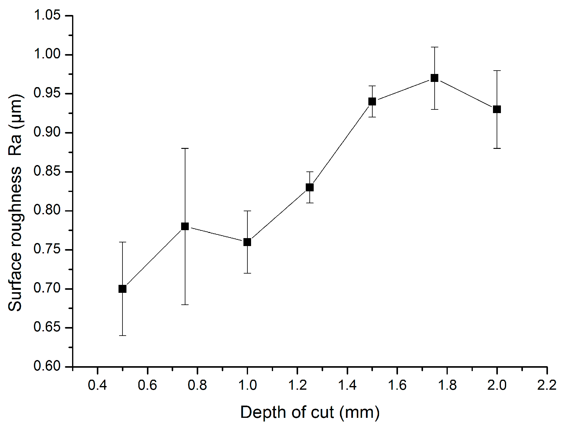
3.3.3. Influence of the Depth of Cut

Figure 21 shows the evolution of surface roughness against depth of cut. Basically, the surface roughness increases with the increase of the depth of cut. When the depth of cut increases from 0.75 mm to 1.0 mm, the surface roughness decreases slightly. Yao et al. [51] reported that when the depth of cut increased, the unit time cutting volume increased and so did the turning force, which caused a severe extrusion between the chip and the rake face. Thus, surface roughness rises with the increase of the depth of cut. More heat is generated with the increasing depth of cut, which softens the surface layer of the workpiece. Meanwhile, for the cutting edge, heat dissipates easily because of the increasing depth of cut. Therefore, the wear of the cutting tool slows. The combination of these factors leads to the small drop of the surface roughness.

4. Conclusions

In the present study, the experiments about machining performance of TiAlN-coated cemented carbide tools with chip groove are carried out for machining of TC7 under dry conditions. The novelty of the study is proved in the paper. The mechanisms of wear, tool life, and surface roughness are investigated. The following conclusions can be drawn:
1. The machining performance of TiAlN-coated cemented carbide tools with chip groove is better than uncoated carbide tools (K20) in the machining of titanium alloy TC7 under dry conditions. The optimal cutting speed, feed rate, and depth of cut are 60 m/min, 0.10 mm/r, and 1.0 mm, respectively. The better wear resistance, tool life, and surface roughness can be achieved under reasonable parameters of machining.
2. A uniform wear band occurs on the flank face of TiAlN-coated cemented carbide tools with chip groove. Adhesion, adhesive wear, diffusion wear, crater wear, and stripping are dominant wear mechanisms, and a built-up edge with large size forms on the rake face. With the increase of the cutting speed, wear of the tool becomes serious and the built-up edge becomes unstable, and even craters form. At the cutting speed of 70 m/min, serious plastic deformation occurs on the flank face. For the uncoated carbide tool (K20), the adhesion of the workpiece material is the main wear mechanism. The built-up edge is serious on the rake face.
3. The surface roughness Ra decreases with the increase of the cutting speed, but it increases with the increase of the feed rate. The small surface roughness is acquired at a relatively reasonable cutting speed, feed rate, and depth of cut at 50 m/min, 0.1 mm/r, and 1 mm, respectively. The feed rate is the most dominant parameter for the surface roughness and is followed by the cutting speed. The depth of cut has little effect on the change of surface roughness. The chip groove is utilized fully with the increasing feed rate, thus, the chip breaks in a segmented shape with small radius.
In the present study, the chip is used to explain the results. The limitation of the study is that the chip is not studied deeply.

Author Contributions

Revisions: Z.R.; review and editing: S.Q.; checks: C.Y. and Y.Z.; and validation: X.L.

Funding

This research received no external funding.

Conflicts of Interest

The authors declare no conflict of interest.

References

  1. Jaffery, S.I.; Mativenga, P.T. Wear mechanisms analysis for turning Ti-6Al-4V—Towards the development of suitable tool coatings. Int. J. Adv. Manuf. Technol. 2012, 58, 479–493. [Google Scholar] [CrossRef]
  2. Deng, J.X.; Li, Y.S.; Song, W.L. Diffusion wear in dry cutting of Ti-6Al-4V with WC/Co carbide tools. Wear 2008, 265, 1776–1783. [Google Scholar]
  3. Ruggiero, A.; D’Amato, R.; Gómez, E.; Merola, M. Experimental comparison on tribological pairs UHMWPE/TIAL6V4 alloy, UHMWPE/AISI316L austenitic stainless and UHMWPE/Al2O3 ceramic, under dry and lubricated conditions. Tribol. Int. 2016, 96, 349–360. [Google Scholar] [CrossRef]
  4. Ruggiero, A.; D’Amato, R.; Gómez, E. Experimental analysis of tribological behavior of UHMWPE against AISI420C and against TiAl6V4 alloy under dry and lubricated conditions. Tribol. Int. 2015, 92, 154–161. [Google Scholar] [CrossRef]
  5. Bai, D.S.; Sun, J.F.; Chen, W.Y.; Wang, T.M. Wear mechanisms of WC/Co tools when machining high-strength titanium alloy TB6 (Ti-10V-2Fe-3Al). Int. J. Adv. Manuf. Technol. 2016, 90, 2863–2874. [Google Scholar] [CrossRef]
  6. Sharma, A.; Sharma, M.D.; Sehgal, R. Experimental Study of Machining Characteristics of Titanium Alloy (Ti–6Al–4V). Arabian J. Sci. Eng. 2012, 38, 3201–3209. [Google Scholar] [CrossRef]
  7. Sartori, S.; Moro, L.; Ghiotti, A.; Bruschi, S. On the tool wear mechanisms in dry and cryogenic turning Additive Manufactured titanium alloys. Tribol. Int. 2017, 105, 264–273. [Google Scholar] [CrossRef]
  8. Pramanik, A. Problems and solutions in machining of titanium alloys. Int. J. Adv. Manuf. Technol. 2014, 70, 919–928. [Google Scholar] [CrossRef]
  9. Zhang, S.; Li, J.F.; Deng, J.X.; Li, Y.S. Investigation on diffusion wear during high-speed machining Ti-6Al-4V alloy with straight tungsten carbide tools. Int. J. Adv. Manuf. Technol. 2008, 44, 17–25. [Google Scholar] [CrossRef]
  10. Liu, Z.; An, Q.; Xu, J.; Chen, M.; Han, S. Wear performance of (nc-AlTiN)/(a-Si3N4) coating and (nc-AlCrN)/(a-Si3N4) coating in high-speed machining of titanium alloys under dry and minimum quantity lubrication (MQL) conditions. Wear 2013, 305, 249–259. [Google Scholar] [CrossRef]
  11. Ginting, A.; Nouari, M. Surface integrity of dry machined titanium alloys. Int. J. Mach. Tool Manuf. 2009, 49, 325–332. [Google Scholar] [CrossRef]
  12. Goindi, G.S.; Sarkar, P. Dry machining: A step towards sustainable machining–challenges and future directions. J. Clean Prod. 2017, 165, 1557–1571. [Google Scholar] [CrossRef]
  13. Venugopal, K.A.; Paul, S.; Chattopadhyay, A.B. Tool wear in cryogenic turning of Ti-6Al-4V alloy. Cryogenics 2007, 47, 12–18. [Google Scholar] [CrossRef]
  14. Chang, Y.Y.; Lai, H.M. Wear behavior and cutting performance of CrAlSiN and TiAlSiN hard coatings on cemented carbide cutting tools for Ti alloys. Surf. Coat. Technol. 2014, 259, 152–158. [Google Scholar] [CrossRef]
  15. Kaynak, Y.; Karaca, H.E.; Noebe, R.D.; Jawahir, I.S. Tool-wear analysis in cryogenic machining of NiTi shape memory alloys: A comparison of tool-wear performance with dry and MQL machining. Wear 2013, 306, 51–63. [Google Scholar] [CrossRef]
  16. Lei, Y.; Meng, Q.S.; Zhuang, L.; Chen, S.P.; Dai, J.J. Oxidation behavior of AlMgB14-TiB2 composite at elevated temperature. Appl. Surf. Sci. 2015, 347, 155–161. [Google Scholar] [CrossRef]
  17. Cook, B.A.; Harringa, J.L.; Anderegg, J.; Russell, A.M.; Qu, J.; Blau, P.J.; Higdon, C.; Elmoursi, A.A. Analysis of wear mechanisms in low-friction AlMgB14-TiB2 coatings. Surf. Coat. Technol. 2010, 205, 2296–2301. [Google Scholar] [CrossRef]
  18. Nouari, M.; Makich, H. Experimental investigation on the effect of the material microstructure on tool wear when machining hard titanium alloys: Ti-6Al-4V and Ti-555. Int. J. Refract. Met. Hard Mater. 2013, 41, 259–269. [Google Scholar] [CrossRef]
  19. Çelik, Y.H.; Kilickap, E.; Güney, M. Investigation of cutting parameters affecting on tool wear and surface roughness in dry turning of Ti-6Al-4V using CVD and PVD coated tools. J. Braz. Soc. Mech. Sci. Eng. 2016, 39, 2085–2093. [Google Scholar] [CrossRef]
  20. Tan, G.Y.; Liu, G.J.; Li, G.H. Experimental study on adhesive wear of milling insert with complex groove. Int. J. Adv. Manuf. Technol. 2009, 44, 631–637. [Google Scholar] [CrossRef]
  21. Wanigarathne, P.C.; Kardekar, A.D.; Dillon, O.W.; Poulachon, G.; Jawahir, I.S. Progressive tool-wear in machining with coated grooved tools and its correlation with cutting temperature. Wear 2005, 259, 1215–1224. [Google Scholar] [CrossRef]
  22. Jawahir, I.S.; Ghosh, R.; Fang, X.D.; Li, P.X. An investigation of the effects of chip flow on tool-wear in machining with complex grooved tools. Wear 1995, 184, 145. [Google Scholar] [CrossRef]
  23. Jawahir, I.S.; Li, P.X.; Gosh, R.; Exner, E.L. A New parametric approach for the assessment of comprehensive tool wear in coated grooved tools. CIRP Ann. Manuf. Technol. 1995, 44, 49–54. [Google Scholar] [CrossRef]
  24. Ee, K.C.; Balaji, A.K.; Li, P.X.; Jawahir, I.S. Force decomposition model for tool-wear in turningwith grooved cutting tools. Wear 2002, 249, 985. [Google Scholar] [CrossRef]
  25. Pereira, R.B.D.; Braga, D.U.; Nevez, F.O.; Da Silva, A.S.C. Analysis of surface roughness and cutting force when turning AISI 1045 steel with grooved tools through Scott–Knott method. Int. J. Adv. Manuf. Technol. 2013, 69, 1431–1441. [Google Scholar] [CrossRef]
  26. Ayed, Y.; Germain, G.; Ammar, A.; Furet, B. Degradation modes and tool wear mechanisms in finish and rough machining of Ti17 Titanium alloy under high-pressure water jet assistance. Wear 2013, 305, 228–237. [Google Scholar] [CrossRef] [Green Version]
  27. Venugopal, K.A.; Paul, S.; Chattopadhyay, A.B. Growth of tool wear in turning of Ti-6Al-4V alloy under cryogenic cooling. Wear 2007, 262, 1071–1078. [Google Scholar] [CrossRef]
  28. Wagner, V.; Baili, M.; Dessein, G. The relationship between the cutting speed, tool wear, and chip formation during Ti-5553 dry cutting. Int. J. Adv. Manuf. Technol. 2014, 76, 893–912. [Google Scholar] [CrossRef] [Green Version]
  29. Jawaid, A.; Sharif, S.; Koksal, S. Evaluation of wear mechanisms of coated carbide tools when face milling titanium alloy. J. Mater. Process. Technol. 2000, 99, 266–274. [Google Scholar] [CrossRef]
  30. Zareena, A.R.; Veldhuis, S.C. Tool wear mechanisms and tool life enhancement in ultra-precision machining of titanium. J. Mater. Process. Technol. 2012, 212, 560–570. [Google Scholar] [CrossRef]
  31. Sun, F.J.; Qu, S.; Pan, Y.; Li, X.; Yang, C. Machining performance of a grooved tool in dry machining Ti-6Al-4V. Int. J. Adv. Manuf. Technol. 2014, 73, 613–622. [Google Scholar] [CrossRef]
  32. Ramana, M.V.; Aditya, Y.S. Optimization and influence of process parameters on surface roughness in turning of titanium alloy. Mate. Today Proceed. 2017, 4, 1843–1851. [Google Scholar] [CrossRef]
  33. Moura, R.R.; Da Silva, M.B.; Machado, Á.R.; Sales, W.F. The effect of application of cutting fluid with solid lubricant in suspension during cutting of Ti-6Al-4V alloy. Wear 2015, 332, 762–771. [Google Scholar] [CrossRef]
  34. Phapale, K.; Patil, S.; Kekade, S.; Jadhav, S.; Powar, A.; Supare, A.; Singh, R.K.P. Tool wear investigation in dry and high pressure coolant assisted machining of titanium alloy Ti6Al4V with variable α and β volume fraction. Procedia Manuf. 2016, 6, 154–159. [Google Scholar] [CrossRef]
  35. Jaffery, S.I.; Mativenga, P.T. Assessment of the machinability of Ti-6Al-4V alloy using the wear map approach. Int. J. Adv. Manuf. Technol. 2008, 40, 687–696. [Google Scholar] [CrossRef]
  36. Rahman Rashid, R.A.; Palanisamy, S.; Sun, S.; Dargusch, M.S. Tool wear mechanisms involved in crater formation on uncoated carbide tool when machining Ti6Al4V alloy. Int. J. Adv. Manuf. Technol. 2016, 83, 1457–1465. [Google Scholar] [CrossRef]
  37. Chetan; Behera, B.C.; Ghosh, S.; Rao, P.V. Wear behavior of PVD TiN coated carbide inserts during machining of Nimonic 90 and Ti6Al4V superalloys under dry and MQL conditions. Ceram. Int. 2016, 42, 14873–14885. [Google Scholar] [CrossRef]
  38. Sun, S.J.; Brandt, M.; Palanisamy, S.; Dargusch, M.S. Effect of cryogenic compressed air on the evolution of cutting force and tool wear during machining of Ti-6Al-4V alloy. J. Mater. Process. Technol. 2015, 221, 243–254. [Google Scholar] [CrossRef]
  39. Oliaei, S.N.B.; Karpat, Y. Investigating the influence of built-up edge on forces and surface roughness in micro scale orthogonal machining of titanium alloy Ti6Al4V. J. Mater. Process. Technol. 2016, 235, 28–40. [Google Scholar] [CrossRef] [Green Version]
  40. Hatt, O.; Crawforth, P.; Jackson, M. On the mechanism of tool crater wear during titanium alloy machining. Wear 2017, 374, 15–20. [Google Scholar] [CrossRef]
  41. Chetan; Narasimhulu, A.; Ghosh, S.; Rao, P.V. Study of tool wear mechanisms and mathematical modeling of flank wear during machining of Ti alloy (Ti6Al4V). J. Inst. Eng. India Ser. C 2014, 96, 279–285. [Google Scholar] [CrossRef]
  42. Duong, X.T.; Mayer, J.R.R.; Balazinski, M. Initial tool wear behavior during machining of titanium metal matrix composite (TiMMCs). Int. J. Refract. Met. Hard Mater. 2016, 60, 169–176. [Google Scholar] [CrossRef]
  43. Che-Haron, C.H. Tool life and surface integrity in turning titanium alloy. J. Mater. Process. Technol. 2001, 118, 231–237. [Google Scholar] [CrossRef]
  44. Jawaid, A.; Che-Haron, C.H.; Abdullah, A. Tool wear characteristics in turning of titanium alloy Ti-6246. J. Mater. Process. Technol. 1999, 92, 329–334. [Google Scholar] [CrossRef]
  45. Astakhov, V.P. Effects of the cutting feed, depth of cut, and workpiece (bore) diameter on the tool wear rate. Int. J. Adv. Manuf. Technol. 2006, 34, 631–640. [Google Scholar] [CrossRef]
  46. Ee, K.C.; Li, P.X.; Balaji, A.K.; Jawahir, I.S.; Stevenson, R. Performance-based predictive models and optimization methods for turning operations and applications: Part 1-Tool wear/tool life in turning with coated grooved tools. J. Manuf. Process. 2006, 8, 54–66. [Google Scholar] [CrossRef]
  47. Raza, S.W.; Pervaiz, S.; Deiab, I. Tool wear patterns when turning of titanium alloy using sustainable lubrication strategies. Int. J. Precis. Eng. Manuf. 2014, 15, 1979–1985. [Google Scholar] [CrossRef]
  48. Nithyanandam, J.; LalDas, S.; Palanikumar, K. Surface roughness analysis in turning of titanium alloy by nanocoated carbide insert. Procedia Mater. Sci. 2014, 5, 2159–2168. [Google Scholar] [CrossRef]
  49. Helu, M.; Behmann, B.; Meier, H.; Dornfeld, D.; Lanza, G.; Schulze, V. Impact of green machining strategies on achieved surface quality. CIRP Annals Manuf. Technol. 2012, 61, 55–58. [Google Scholar] [CrossRef]
  50. Ramesh, S.; Karunamoorthy, L.; Palanikumar, K. Measurement and analysis of surface roughness in turning of aerospace titanium alloy (gr5). Measurement 2012, 45, 1266–1276. [Google Scholar] [CrossRef]
  51. Yao, C.F.; Lin, J.N.; Wu, D.X.; Ren, J.X. Surface integrity and fatigue behavior when turning γ-TiAl alloy with optimized PVD-coated carbide inserts. Chin. J. Aeronaut. 2018, 31, 826–836. [Google Scholar] [CrossRef]
Figure 1. Microstructures of the titanium alloy TC7.
Metals 08 00850 g001
Figure 2. Two inserts and tool holder.
Metals 08 00850 g002
Figure 3. Geometry of the chip groove: TiAlN-coated insert.
Metals 08 00850 g003
Figure 4. SEM images of flank face of the TiAlN-coated insert after machining for 6 min (cutting speed of 40 m/min, feed rate of 0.1 mm/r, depth of cut of 1.0 mm): (a) flank face; (b) flank face close to nose; and (c) magnification of Figure 4b.
Metals 08 00850 g004
Figure 5. Analysis of chemical composition for points selected in Figure 4b: (a) point A; (b) point B; and (c) point C.
Metals 08 00850 g005
Figure 6. SEM image of flank face of the TiAlN-coated insert after machining for 6 min (cutting speed of 70 m/min, feed rate of 0.1 mm/r, depth of cut of 1.0 mm).
Metals 08 00850 g006
Figure 7. SEM images of flank face of the uncoated insert (K20): (a) cutting speed of 50 m/min, cutting time of 3 min; (b) magnification of adhesion in Figure 7a; and (c) cutting speed of 60 m/min, cutting time of 6 min; (feed rate of 0.1 mm/r and depth of cut of 1.0 mm for (ac)).
Metals 08 00850 g007
Figure 8. SEM image of rake face of the TiAlN-coated insert after machining for 6 min (cutting speed of 50 m/min, feed rate of 0.1 mm/r, depth of cut of 1.0 mm).
Metals 08 00850 g008
Figure 9. Analysis of chemical composition for point selected at point A in Figure 8.
Metals 08 00850 g009
Figure 10. SEM image of rake face of the TiAlN-coated insert after machining for 12 min (cutting speed of 50 m/min, feed rate of 0.1 mm/r, depth of cut of 1.0 mm).
Metals 08 00850 g010
Figure 11. SEM image of rake face of the TiAlN-coated insert after machining for 6 min (cutting speed of 60 m/min, feed rate of 0.1 mm/r, depth of cut of 1.0 mm).
Metals 08 00850 g011
Figure 12. SEM images of rake face of the uncoated insert (K20): (a) cutting speed of 50 m/min, cutting time of 3 min; (b) magnification of tool nose in Figure 12a; and (c) cutting speed of 60 m/min, cutting time of 6 min; (feed rate of 0.1 mm/r and depth of cut of 1.0 mm for (ac)).
Metals 08 00850 g012
Figure 13. Evolution of VB against cutting time at different cutting speeds (feed rate of 0.1 mm/r, depth of cut of 1.0 mm).
Metals 08 00850 g013
Figure 14. Evolution of VB against cutting time at different feed rates (cutting speed of 50 m/min, depth of cut of 1.0 mm).
Metals 08 00850 g014
Figure 15. SEM images of the TiAlN-coated insert at feed rate of 0.2 mm/r after machining for 12 min (cutting speed of 50 m/min, depth of cut of 1.0 mm): (a) rake face; and (b) flank face.
Metals 08 00850 g015
Figure 16. SEM images of the TiAlN-coated inserts at feed rate of 0.05, 0.15 mm/r after machining for 12 min, respectively (cutting speed of 50 m/min, depth of cut of 1.0 mm): (a) feed rate of 0.05 mm/r; and (b) feed rate of 0.15 mm/r.
Metals 08 00850 g016
Figure 17. Evolution of VB against cutting time at different depths of cut (cutting speed of 50 m/min, feed rate of 0.1 mm/r).
Metals 08 00850 g017
Figure 18. Evolution of surface roughness against cutting time at different cutting speeds (feed rate of 0.1 mm/r, depth of cut of 1.0 mm).
Metals 08 00850 g018
Figure 19. Evolution of surface roughness against cutting time at different feed rates (cutting speed of 50 m/min, depth of cut of 1.0 mm).
Metals 08 00850 g019
Figure 20. Evolution of the breakage of the chip with the increase of the feed rate (cutting speed of 50 m/min, depth of cut of 1.0 mm): (a) feed rate of 0.05 mm/r; (b) feed rate of 0.1 mm/r; (c) feed rate of 0.15 mm/r; and (d) feed rate of 0.2 mm/r.
Metals 08 00850 g020
Figure 21. Evolution of the surface roughness against different depths of cut (cutting speed of 50 m/min, feed rate of 0.1 mm/r).
Metals 08 00850 g021
Table 1. Chemical composition of TC7.
ElementAlTiCrFeSiBCHON
wt.%5.2989.280.600.380.310.0110.005<0.0010.0530.006
Table 2. Mechanical properties of TC7.
Yield Strength (MPa)Tensile Strength (MPa)Elongation (%)Reduction of Cross-section Area (%)Elastic Modulus (GPa)Poisson’s RatioMicro Hardness (HV)
81091012.830113.70.296360
Table 3. Geometrical parameters of insert fixed in the tool holder.
Relief AngleCutting Edge AngleMinor Cutting Edge AngleNose Radius
95°0.4 mm

