Article

Effect of T6 Heat Treatment on the Microstructure and Hardness of Secondary AlSi9Cu3(Fe) Alloys Produced by Semi-Solid SEED Process

Department of Management and Engineering, University of Padova, Stradella S. Nicola, 3 I-36100 Vicenza, Italy
*
Author to whom correspondence should be addressed.
Metals 2018, 8(10), 750; https://doi.org/10.3390/met8100750
Submission received: 3 September 2018 / Revised: 17 September 2018 / Accepted: 19 September 2018 / Published: 23 September 2018
(This article belongs to the Special Issue Heat Treatment of Aluminum Alloys)

Abstract

:
The effect of the T6 heat treatment on the microstructure and hardness of a secondary semi-solid AlSi9Cu3(Fe) alloy have been investigated by using optical, scanning and transmission electron microscopy and hardness testing. The semi-solid alloy was produced using the swirled enthalpy equilibration device (SEED). The solution heat treatments were performed at 450, 470 and 490 °C for 1 to 6 h followed by water quenching and artificial ageing at 160, 180 and 220 °C for holding times ranging from 1 to 30 h. The microstructural investigations have revealed the spheroidization of the eutectic Si and the dissolution of the majority of Cu-rich compounds after all the solution heat treatments; moreover, the greater the solution temperature and time, the higher the hardness of the alloy. Unacceptable surface blistering has been observed for severe solution condition, 490 °C for 3 and 6 h. The artificial ageing at 160 °C for 24 h has led to the highest alloy strengthening thanks to the precipitation of β” and Q’ (or L) phases within the α-Al matrix. The hardening peaks at higher temperatures have been early achieved due to faster hardening kinetic; however, the lower number density of β” and Q’ (or L) phases and the presence of coarser θ’ precipitates result in a reduction of hardness values for peak aged condition at 180 and 220 °C, respectively.

1. Introduction

Aluminium-silicon casting alloys are widely used in the automotive industry due to their good castability, good corrosion resistance, high strength stiffness to weight ratio as well as recycling possibilities at low energy costs. Furthermore, mechanical properties of as-cast components can significantly be improved by suitable heat treatments. However, the application of a post-casting thermal treatment on high-pressure die-cast (HPDC) components is still a limited practice in industry. Due to the extreme turbulent flow of molten metal during filling of the die cavity, internal or sub-surface porosity, originated from entrapped gases, can usually occur in the diecastings [1]; consequently, during typical thermal treatment at elevated temperature (470÷500 °C [2]), gas expansion can produce unacceptable surface blisters on the components [2,3].
Beside the use of vacuum-assisted HPDC to reduce the level of entrapped gas [4], semi-solid metal (SSM) processes have been considered a valid alternative for producing sound Al-Si-based light-weight parts with satisfactory response to heat treatments, especially for the automotive sector. Some examples are fuel rails, control arms, steering knuckles, engine brackets, or even engine blocks [5,6,7].
Generally, SSM processing is divided into two main categories such as rheocasting and thixocasting. The former involves the preparation of a SSM slurry directly from the molten metal, which is cooled and stirred up to the desired solid fraction, followed by forming process. Nowadays, this approach is more widely used than thixocasting where a specially prepared alloy (with globular or rosette-like α-Al grains) is reheated to the desired semi-solid forming temperature prior to casting.
Contrary to the turbulent metal flow during die cavity filling in conventional HPDC, both the SSM casting approaches experience a laminar flow of semi-solid metal having a higher viscosity than the liquid state; consequently, the risk of gas entrapment is largely limited and blistering phenomena are prevented during further heat treatments or welding operations [8].
The typical thermal treatment for automotive components made by Al foundry alloy is T6 temper, which generally induces higher alloy strengthening. The T6 thermal cycle consists of a solution heat treatment followed by a water quenching and then an age hardening (or precipitation hardening). The solution heat treatment leads to the dissolution of intermetallic phases and the spheroidization of eutectic Si with a resulting improvement of alloy ductility [9,10]. The time for solution treatment is strongly dependent on the microstructural scale [10], ranging from few minutes up to several hours [11,12,13]. In general, too short solution treatment does not guarantee that all alloying elements are dissolved in the α-Al matrix and made available for further precipitation hardening; on the contrary, too long solution treatment shows economic limitations because it uses more energy and time than necessary.
Age hardening at room temperature (natural ageing) or elevated temperature (artificial ageing, AA) increases the alloy strengthening because of the ultra-fine particles which precipitate from the supersaturated solid solution and act as obstacles to the dislocation movement.
In the last years, an increasing attention from researchers has been paid on the heat treatment sequence of primary semi-solid Al-Si cast alloys such as A356, A357 alloys [14,15,16] in order to increase their mechanical properties. However, to date, only few studies have investigated the age hardening response of a secondary (or recycled) Al-Si alloy produced via SSM route [17] although secondary Al foundry alloys are the most used Al diecasting alloys in the automotive industry.
In this work, the microstructure evolution and the precipitation hardening response of a rheocast secondary AlSi9Cu3(Fe) alloy used for automotive components were investigated as a function of different T6 heat treating parameters.

2. Materials and Methods

In this study, automotive components (lower suspension arm) were manufactured with a secondary AlSi9Cu3(Fe) alloy (EN AC-46000) by the Swirled Enthalpy Equilibration Device (SEED), which operates by using a liquid-based method (rheocasting) for producing the Al slurry over a wide range of Al-Si alloy compositions (up to 17 wt.% Si) [18,19].
According to this process, the slurry is prepared by means of three stages [18]. Firstly, the molten metal of the desired composition and temperature is poured into a vessel whose thermal capacity is able to cool the alloy in order to obtain the desired solid fraction in the range between 30 and 45%. During this stage, the vessel is swirled to homogenize the temperature and the distribution of the solid phase which is generated at the walls of the vessel. The duration of this stage depends upon the dimensions of the container and the mass of the charge, even if an extremely close control of the mixing time is not necessary. Furthermore, Doutre et al. [18] demonstrated how the mixing intensity does not affect the process yield over the range of 150 to 300 rpm.
In the second stage of the process, a valve at the bottom of the vessel can be opened and some of the remaining liquid phase is drained to produce a self-supporting semi-solid billet, which is depleted in the eutectic forming elements (Si, Mg, Fe) and enriched in the peritectic forming element (Ti) [18].
In the third stage, the vessel is inverted, and the billet is de-moulded and transferred to the forming unit.
Information about the SEED method and processing parameters are reported in the Ref. [18,20] where the potential of the SEED process as a route of preparing high quality feedstock has been also tested to produce an automotive front upper control arm weighing approximately 1 kg.
In the present work, the ingots were supplied by Raffineria Metalli Capra Spa (Brescia, Italy) while the demonstrators were produced at the CIE Automotive (Bilbao, Spain). The chemical composition of the alloy, measured on separately poured samples, is shown in Table 1.
The ingots were firstly melted at 670 °C in a tower furnace of 800-kg capacity and then the molten metal was tapped into an electric resistance furnace where it was N-degassed with a rotary degasser (MTS Rotor Ø190, at 600 rpm, Foseco Española S.A., Izurtza, Spain) for 8 min. The metal was manually skimmed and held at 640 °C. No grain refinement or chemical eutectic modification were performed.
The melt was transferred by means of a ladle and poured into a steel vessel preheated at about 130 °C to avoid thermal shock and to better control the amount of solid fraction. At this stage, in order to improve the distribution of the primary solid phase, the vessel was swirled for 115 s at a rate of 150 rpm with an eccentricity of the swirl motion. To achieve homogenisation of the temperature and structure, a delay time of 10 s was maintained before transferring the slurry to the shoot sleeve of a cold camber die casting machine. Then, the slurry was injected into the die cavity and the plunger velocity of the HPDC machine (Petransa, Alió, Tarragona, Spain) was lower than 1 ms−1 for the filling phase; once the die-cavity was filled, a pressure of ~115 MPa was applied to guarantee high-integrity castings. Detailed investigations and results regarding the final rheocasting quality are described in Ref. [21].
A calorimetry analysis of the as-rheocast alloy was preliminary performed with a Labsys Evo differential scanning calorimeter (DSC) (SETARAM Instrumentation, Caluire, France) to identify the solidification reaction sequence of the alloy. The samples in the form of 4 mm discs weighting approximately 30 mg were drawn from the castings. Samples were weighted before and after DSC scan and no significant mass increase was observed. The DSC test was carried out with an empty reference pan, as cooling (solidification) scan in a protective gas atmosphere of pure Argon. The sample was heated up to 800 °C at 2 °C/min and maintained at this temperature for 15 min before cooling to room temperature at 2 °C/min.
Specimens of about 30 × 10 × 15 mm3 size were drawn from the as-rheocast components and they were heat treated according to the following conditions: solution treatment inside an electric-resistance heated-air-circulating furnace, water quenching at room temperature and then artificial ageing. The solution treatments were performed at 450, 470 and 490 °C for 1, 3 and 6 h, respectively. These process parameters were selected in order to minimize blistering and residual stresses in the castings after water quenching and to reduce the risk of localised incipient melting of Cu-rich compounds. Moreover, the experimental solution treatments were also chosen in accordance with the conventional solution cycles normally applied in the automotive industry, where shortening the total time is a key issue to increase the productivity and to reduce the manufacturing cost [11,12,13].
As mentioned before, after the solution heat treatment, the specimens were water quenched at room temperature. To avoid natural ageing prior to the artificial ageing, the specimens were stored at 4 °C for 1 day; subsequently, the artificial ageing was carried out respectively at 160, 180 and 220 °C for different ageing times ranging between 1 and 30 h. The temperature control during solution and ageing treatments was ±1 °C.
The heat-treated specimens were mechanically prepared by grinding with abrasive SiC papers and polishing with 6- and 3-µm diamond pastes and colloidal silica suspension. Optical microscope and quantitative metallographic analysis were used to determine the main characteristics of eutectic Si particles (size and aspect ratio) and the amount of undissolved Cu-rich phases. Before the quantification, the polished samples were chemically etched by using a water solution of HNO3 at 70 °C to improve the contrast of Cu-rich phases. A FEI Quanta™ 250 scanning electron microscope (SEM) (Thermo Fisher Scientific, Hillsboro, OR, USA) operating at 20 kV and coupled with an energy dispersive spectrometer (EDS) (EDAX™, AMETEK BV, Tilburg, The Netherlands) and an electron back-scattered diffraction (EBSD) (EDAX™, AMETEK BV, Tilburg, The Netherlands) detector was used to study the nature and the distribution of the intermetallic phases.
In order to better understand the effects of the ageing treatment on the alloy microstructure, peak ageing conditions at 160, 180 and 220 °C were selected for an extended microstructural characterization by using a JEM™ 2000 EX II transmission electron microscope (TEM) (JEOL Ltd, Akishima, Japan) operating at 200 kV. In particular, TEM observations supported by selected area electron diffraction (SAED) analyses were carried out to study the phase precipitation in the α-Al phase. TEM specimens were mechanically prepared according to standard practice. Finally, the TEM discs (3 mm diameter, ~25 μm thickness) were processed by ion milling up to the electron transparency using precision ion polishing system (PIPS, Model 691, Gatan, Pleasanton, CA, USA).
In order to evaluate the strengthening response of the alloy as function of the solution and ageing treatments, Vickers hardness measurements were performed on each sample by applying a load of 60 kgf, in accordance to the standard ASTM E92-17, and the average hardness values were reported. The hardness evolution of the alloy allowed to easily individuate the peak ageing (temperature, time), that is the greatest material hardening obtained during ageing treatment.

3. Results and Discussion

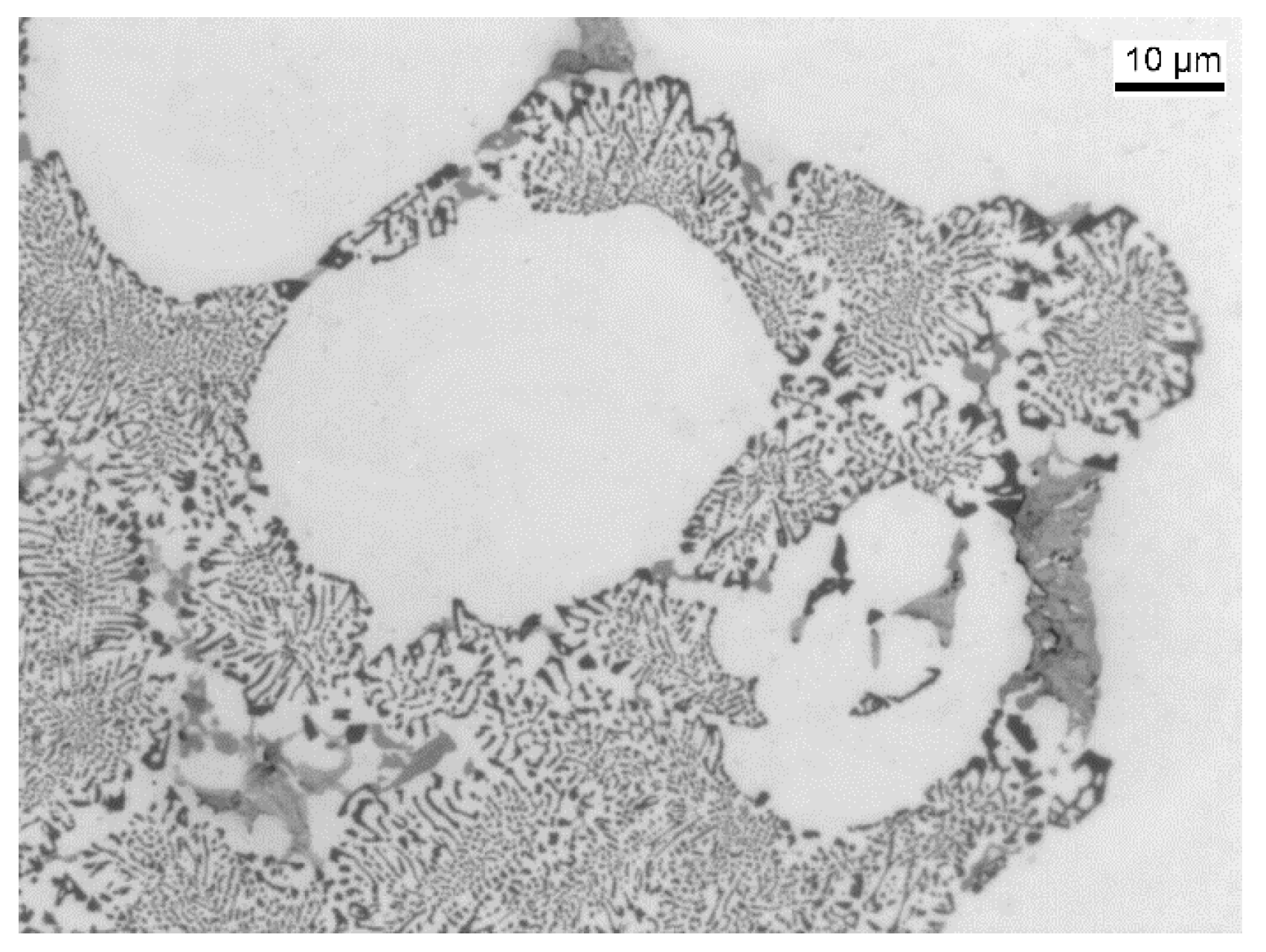
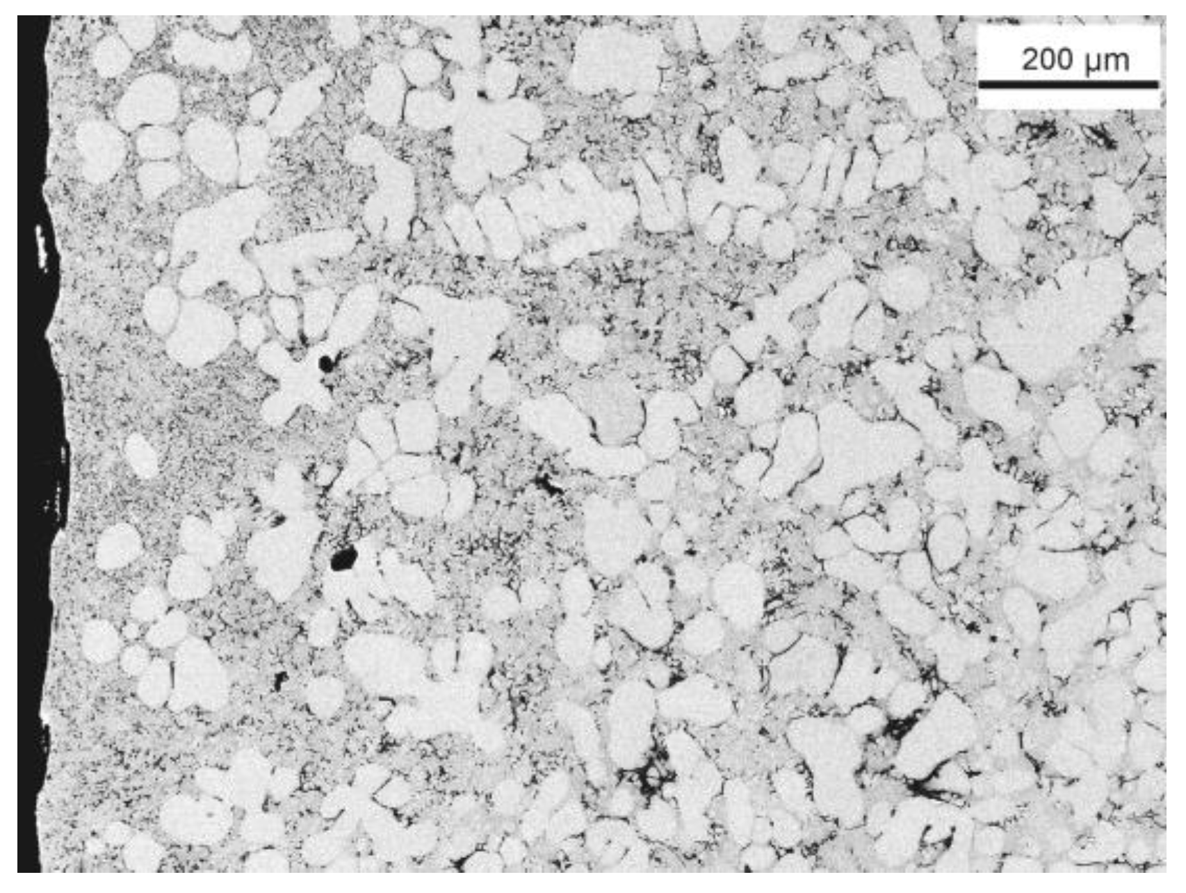
3.1. As-Rheocast Condition

The microstructure of the as-rheocast AlSi9Cu3(Fe) alloy exhibits the typical structure of rheocast Al-Si alloy, characterized by globular or rosette-like primary α-Al crystals surrounded by the Al-Si eutectic network (Figure 1). The shape of the α-Al crystals is due to the fragmentation of the α-Al dendrites due to the swirl motion during the SEED process. As reported in Ref. [21], the average size of the primary α-Al crystals, estimated by quantitative image analysis, results in ~70 μm with an aspect ratio of 1.6. Moreover, the volume fraction of the primary α-Al phase is 55 ± 6%.
The eutectic Si particles generally show fibrous morphology, as illustrated in Figure 2. It is worth noticing that a larger amount of Al-Si eutectic is observed near to the casting surface (Figure 3): this microstructural inhomogeneity is due to liquid segregation phenomena occurring during the SSM processing, as described in Ref. [22,23].
In Figure 4, the DSC cooling curve of AlSi9Cu3(Fe) alloy is plotted. The thermogram reveals the liquidus and solidus temperatures approximately at 610 and 485 °C, respectively, and according to Ref. [24], the sequence of phase precipitation during the solidification path can be identified as following: primary Fe-rich phase (~612 °C), α-Al crystals (~578 °C), eutectic Si and Fe-containing phases (~567 °C), Al2Cu phase (~503 °C) and formation of eutectic structures containing Al2Cu and Al5Mg8Si2Cu2 (~498 °C).
Deeper SEM investigations revealed the intermetallic phases distributed solely in the eutectic Al-Si network (Figure 5); in addition, the EDS elemental maps seem to confirm the presence of θ-Al2Cu, polygonal α-Al(Fe,Mn,Cr)Si (α-Fe), acicular β-Al(Fe,Mn)Si (β-Fe) and Q-AlMgSiCu intermetallic phases (Figure 6).
For a more accurate identification of the intermetallic phases, EBSD analyses were performed on the θ-Al2Cu, α-Al(Fe,Mn,Cr)Si and β-Al(Fe,Mn)Si, and the associated EBSD patterns well match the nominal crystallography structures, i.e., tetragonal, cubic and monoclinic crystal systems, respectively [25], as reported in Figure 7.

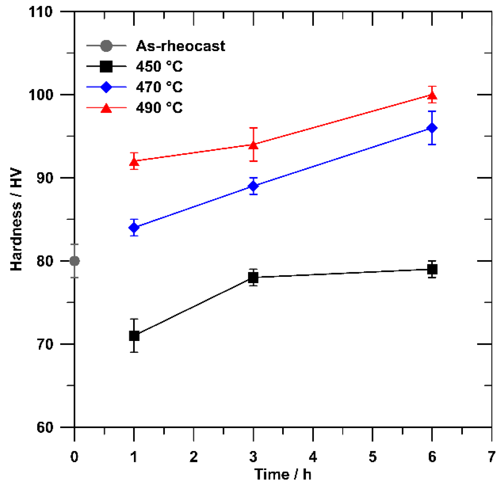
3.2. As-Quenched Condition

The specimens, which were solution heat treated at 450, 470 and 490 °C, showed essentially similar microstructural features. The microstructure of the AlSi9Cu3(Fe) alloy solutioned at 470 °C for 6 h is shown as an example in Figure 8. As expected, the solution treatment has no coarsening effects on the primary α-Al cells, which show a similar size to the as-rheocast condition (~70 μm); while the eutectic Si is considerably modified in size and morphology. The eutectic Si particles fragment and acquire a more round-shape (Figure 8b) due to the reduction of the total Al/Si interfacial energy during the solution treatment; moreover, smaller eutectic Si particles in as-rheocast microstructure dissolve and favour the coarsening of coarser ones according to Ostwald ripening mechanism [26].
The size and morphological variations of the eutectic Si particles as a function of solution treatments are summarized in Table 2. The eutectic Si particles fragment and spheroidize, mainly, during the early stage of the solution treatment; then, they tend to coarsen during the subsequent stage of treatment, maintaining essentially the same shape.
Moreover, fine polygonal and rod/platelet-shape particles appear within the α-Al matrix after solution treatments, as shown in Figure 8b. The EDS profile across the α-Al crystals suggests that the particles are Si-rich phase (Figure 9, red line). The bright field TEM micrograph correlated to SAED investigations confirmed that most of the particles are Si crystals with irregular-polygonal shape (Figure 10).
In the as-rheocast condition, the Si content in the α-Al matrix, over its solubility level at room temperature, is almost homogeneously distributed; this is indicated by the Si profile across the width of an α-Al crystal which appears almost constant (Figure 9, black line). When the alloy is solution heat treated, the excess Si atoms move, clustering and the clusters begin coarsening. Therefore, the final Si particles, crossed by the EDS scan line, cause a corresponding rise of the Si level showing a final “spiky” distribution profile. Moreover, by comparing the elemental profiles in Figure 9, it is thus clear that the precipitation of Si particles in the α-Al phase after the solution treatment leads to a subsequent reduction of the silicon content in the surrounding Al-matrix with respect to the as-rheocast condition.
Similar Si-containing dispersions were also found to form in an Al-7Si-Mg alloy during solution treatments [27]. Moreover, Lasagni et al. [28] showed the presence of nanometrical globular and platelet-like Si precipitates in an Al-1.7Si alloy after solution treatment with a controlled cooling rate (20 K/min) and how the size of Si particles increases by reducing the cooling rate (3 K/min) at the expense of their density. The precipitation of Si particles in the α-Al matrix after solution treatment could thus be ascribed to the excess Si atoms in the supersaturated matrix achieved after the rheocasting process.
The dissolution of Cu-rich compounds was also investigated, as it is generally considered a key-factor for the strengthening enhancement. The fraction of undissolved Cu-rich phases in the as-quenched specimens is reported in Table 2. In the as-rheocast condition, the fraction of Cu-rich compounds is about 2% and it drastically decreases in the earlier stages of solution treatment, more rapidly as the solution temperature increases. In addition, by extending the solution time up to 6 h, the Cu-rich compounds are almost completely dissolved; very few blocky θ-Al2Cu particles remain, being more complex to dissolve if compared to θ-phase in binary eutectic Al + Al2Cu structures and Q-Al5Mg8Si2Cu2 phase, as also resulted from the precipitation sequence in Figure 4. As a consequence of θ-phase dissolution, the Cu level in the α-Al solid solution increases as it clearly appears by comparing the EDS profiles across the α-Al crystals in the as-rheocast condition and after 6 h of solution treatment at 470 °C (Figure 11a). Similar behaviour was also found for the Mg and Zn elements, as reported by the EDS elemental profiles in Figure 11b,c, respectively.
Finally, the different solution treatments do not affect the α-Fe and β-Fe intermetallics because of their high thermal stability, as it results from the DSC thermograph in Figure 4.
The Vickers hardness of the as-quenched AlSi9Cu3(Fe) alloy as a function of the solution treatment conditions is illustrated in Figure 12; the hardness value of as-rheocast alloy has also been reported in the graph.
For the solution conditions considered in this work, it results that the hardness of the alloy increases by increasing the solution temperature and time; therefore, the optimal strengthening response of the alloy is achieved after thermal treatment at the most severe condition.
It is worth noting that the solution treatments carried out at 450 °C led to lower hardness values with respect to as-rheocast condition. In particular, the material softening is larger in the earlier stage of the treatment, then the hardness slightly improves by prolonging the holding time and finally maintains at a steady value after 3 h. Similar behaviour was found for a thixocast 319 alloy solutioned at 500 °C [29]. The initial softening of the alloy may be due to the eutectic Si particles coarsening, which is characterized by the increase of the inter-particle distance of the eutectic Si [30]; on the other side, the subsequent strengthening can be associated with the increasing content of Cu, Mg and Si in solid solution. The hardness evolution approaches the as-rheocast value, and it stabilizes after 4 h, indicating how the α-Al matrix is saturated.
As mentioned, the alloy solutioned at the most severe conditions (i.e., 490 °C for 3 and 6 h) exhibits higher hardness values; however, blistering phenomena were occasionally observed on the specimens’ surface after the aforementioned heat treatment conditions. Blisters are generally associated to the expansion of gas porosity, which includes gas from physical entrapment, gas from lubricant decomposition, and gas initially dissolved in the molten metal (e.g., hydrogen). The discrimination of each contribution to the total porosity due to gas entrapment is not possible in this work. However, the gas porosity due to dissolved hydrogen is not common in pressure casting processes, where the formation of gas pores is mainly attributed to the decomposition of coolant and die lubrication [31].
In the present study, the subsequent ageing treatments were applied to the alloy solutioned at 470 °C for 6 h which achieved high hardness values and, concurrently, showed a free-defects surface.

3.3. Ageing Condition

3.3.1. Hardness Testing

The age hardening behaviour at 160, 180 and 220 °C is shown in Figure 13. The results indicate that the maximum hardness value is achieved at 160 °C for 24 h. By temperature increasing, the peak hardness is reached for shorter times because of faster precipitation kinetics, i.e., 5 h at 180 °C and 2 h at 220 °C. It is well known that the precipitation rate during heat treatment is related to the diffusion of the solute elements in the α-Al matrix and this strictly depends on the temperature [32]. As described in the literature [15], the experimental peak value progressively decreases as the ageing temperature increases: 117 ± 3 HV at 160 °C, 103 ± 3 HV at 180 °C and 95 ± 2 HV at 220 °C. It is worth noting that the hardness in the earlier stages of ageing is slightly lower when compared to the as-quenched condition after the solution treatment at 470 °C for 6 h; for these relative short times, the mechanical response appreciably decreases by decreasing the ageing temperature. As reported by Maksimovic et al. [33], this trend can be ascribed to the dissolution of GP zones formed during previous solution heat treatment.

3.3.2. Precipitation Microstructure

The artificial ageing treatments induce no visible effects at microscale in the alloy. Therefore, high magnification bright field TEM observations were carried out for the peak ageing conditions at 160, 180 and 220 °C, in order to investigate the nature of strengthening phases responsible for the greatest material hardening. Where not differently specified in the text, TEM micrographs and SAED patterns have been acquired close the <100>Al zone axis to have a higher contrast between the precipitates and the matrix.
In an Al-Si-Cu-Mg system, the precipitation sequence is normally considered quite complex because of the occurrence of a great variety of structures that can range from binary to complex quaternary phases. Therefore, a large discrepancy about the strengthening mechanism of Al-Si-Cu-Mg alloys after solution and artificial ageing treatments emerges from the literature; consequently, more experimental investigations are requested to consolidate the understanding of the age hardening mechanism.
In order to support the TEM findings, several works were examined concerning the ageing response of hypoeutectic cast Al-Si-Cu(-Mg) alloys and wrought Al-Mg-Si(-Cu) and Al-Cu-Mg(-Si) alloys. Although the experimental alloy in this work is a foundry Al-Si-based alloy, the α-Al matrix results to be Mg- and Cu-enriched due to the dissolution of the Mg- and Cu-rich intermetallic phases after the solution heat treatment, as illustrated in Figure 11. Moreover, the Si content in the solid solution α-Al matrix is further reduced due the precipitation of Si particles, as previously reported (Figure 9 and Figure 10). Therefore, the age hardening mechanism in wrought Al-Mg-Si or Al-Cu-Mg based alloys has to be also considered in order to better understand the precipitation mechanism in the rheocast AlSi9Cu3(Fe) alloy.
The TEM investigation of the peak ageing condition at 160 °C for 24 h (Figure 14a) reveals a large amount of fine black dots with a square-like shape and an average side length of ~4 nm, homogeneously distributed in the α-Al matrix. Several authors [34,35,36] have reported the presence of very similar precipitates in Al-Mg-Si-(Cu) alloys after ageing treatments and they have been identified as metastable coherent β’’ phase precipitation through the analysis of SAED patterns and high-resolution TEM micrographs. The appearance of nanometric dots with similar size and shape were also observed in an aged AlSi7Cu3Mg alloy by Li et al. [35], who stated that the square-shaped particles correspond to the cross sections of needle-like β’’ precipitates. Some needle-like precipitates that lie along the <100> directions of the α-Al matrix are visible in Figure 14a, confirming the typical orientation relationships between β’’ and α-Al phases [37]. The mean length of needle-like β’’ precipitates along the <100>Al directions was measured about 30 nm.
Beside the black dot particles, some precipitates appear with a rectangular cross-section with mean size of 2 × 57 nm2. By tilting the sample close to <110>Al direction, these precipitates show a lath-shaped morphology (Figure 14b) with a dimension of ~7 nm. Li et al. [35] observed that the lath-shaped precipitates in an aged AlSi7Cu3Mg alloy are quaternary Al-Mg-Si-Cu phase and their chemical composition and crystal structure fit the Q’ phase. The presence of Q’ phase was also observed in an aged AlSi9Cu3.5Mg alloy and the corresponding SAED pattern seems to be close to the experimental one obtained in the present work (see inset in Figure 14a).
It is worth mentioning that, beside Q’ phase, lath-like L precipitates with rectangular cross section and longer dimension lying along the <100>Al direction, can also precipitate in aged Al-Mg-Si-Cu as well [38,39]. Moreover, contrary to the L phase, the Q’-laths section has the long side at an angle of about ~11° with respect to the <100>Al directions or, equivalently, Q’ precipitates have {510}Al habit planes with the Al matrix [36,40,41,42]. In an aged Al-Mg-Si alloy with Cu excess, it is found that the decomposition of the supersaturated solid solution (SSSS) takes place by a complex precipitation sequence [43]:
α(SSSS) → atomic clusters → GP zones → β”,L → β’,Q’ → Q
where the L phase is believed to be a Q’ precursor.
The microstructure for the peak aged condition at 180 °C for 5 h is shown in Figure 15. Parallelogram-like dots and fine needles, associated to Q’ and β’’ phases, are still the predominant precipitates in the alloy. While the dimensions of the precipitates seem comparable to those observed after ageing at 160 °C for 24 h, the precipitate volume fraction appears lower. The SAED pattern (Figure 15) shows some different reflections compared to those observed in the diffraction pattern of the peak-aged condition at 160 °C: due to the complexity of the chemical composition of the examined alloy, the precipitation of an extra phase cannot be excluded.
TEM micrograph of peak aged alloy at 220 °C for 2 h is reported in Figure 16. If compared to previous peak aged conditions, fine parallelogram-like precipitates are not revealed. The significant reduction of β’’ fraction due to the temperature increase from 180 to 220 °C seems in agreement with Yang et al. [44] who found that β’’ precipitates do not easily transform into more stable phases (semi-coherent β’ and Q’ phases) at 175 °C for prolonged time, while the transformation process becomes more rapid at higher temperature (200 °C). In the microstructure, fine precipitates with narrow rectangular morphology and {100}Al habit plane are also present and identified as Q’ phase. The dimensions of these precipitates seem comparable to those observed after ageing at 160 and 180 °C for 24 and 5 h, respectively.
Long needle-like precipitates with a length up to ~150 nm and oriented along <100>Al direction are also observed after ageing at 220 °C for 2 h. By tilting the TEM specimen close to <110>Al direction, the longer needles transform into platelet-shape precipitates (Figure 16b) with an average size of about 4.5 × 10³ nm2. These can be identified as θ’ phase that forms fine platelets (thickness ~1 nm) lying on {100}Al planes, as largely documented in literature for Al-Si-Cu-Mg alloys [35,45,46]. Moreover, the SAED pattern (Figure 16a) shows reflections at {110}Al positions and sharp streaks parallel to the <001>Al direction: by comparing it with the SAED pattern analyses of thermal treated Al-Cu and Al-Si-Cu–based alloys reported in literature [47,48], it can be stated that the experimental diffraction pattern supports that the platelets are consistent with θ’ phase.
The evolution of the volume fraction of precipitates during ageing treatment can be generally estimated according to the Johnson-Mehl-Avrami-Kolmogorov (JMAK) relationship [49]:
fV = fm(1 − exp(−ktn)
where fV is the precipitated volume fraction at a given aging time, t, fm is the maximum volume fraction, k is the overall rate constant that depends on the nucleation and growth rates of the precipitates, and n is a constant usually known as Avrami’s exponent.
The volume fraction of the different phases precipitated at the peak aged conditions and observed during TEM investigations was estimated by isothermal phase transformation calculation using JMatPro® commercial software (Version 7.0, Sente Software Ltd., Guildford, UK) [50], where no phase competition was considered. The values of the precipitation kinetics used in the JMAK equation at the ageing temperatures of 160, 180 and 220 °C are listed in Table 3. The volume fractions of the β’’, Q’ and θ’ phases at the different peak ageing conditions are shown in Figure 17a.
Using Equation (2) and the mean dimensions of the particles measured on the TEM micrographs, the average number density, NV, of the different types of precipitate per unit volume can be calculated at the peak ageing conditions as follows
NV = fV/(w × l × t)
where w, l and t are the average width, length and thickness of β’’, Q’ and θ’ precipitates previously described as needle-, lath- and plate-like particles. The calculated number density of precipitates is shown in Figure 17b.
Figure 17 evidences how the greatest volume fraction as well as the highest number density of β’’ and Q’ phases is obtained by ageing at 160 °C for 24 h. On the other side, the highest volume fraction of θ’ phase is attained after 2 h ageing at 220 °C. However, increasing ageing temperature up to 220 °C leads to the coarsening phenomenon of precipitates as defined by Ostwald ripening theory in which fine precipitates are incorporated into larger ones to reduce the surface energy per volume of system. This can explain the reduced number density of θ’ phase at 220 °C for 2 h (Figure 17b).
Increasing the number density of precipitates per unit volume leads to shortening the distance between fine precipitates. Thus, the hardness of the material is increased accordingly as a function of the different peak ageing condition, i.e., from 95 ± 2 HV (220 °C for 2 h) up to 117 ± 3 HV (160 °C for 24 h). According to the Orowan mechanism, the increased strength of Al matrix can be estimated through the following equation [51]
ΔσOrowan = 0.84MGb/λ
where M is the Taylor factor, G is the shear modulus, b is the Burgers vector and λ is the inter-particle spacing. Then, the Orowan strength is inversely proportional to the inter-particle distance.
According to the Friedel mechanism, the mechanical properties can be also attributed to the ability of the strengthening precipitates to withstand shearing by gliding dislocations [52].
In general, the precipitation hardening progressively increases with the coarsening of the precipitates until they are shared by dislocations. With further increase of the size of precipitates, the dislocations bypass the precipitates via the Orowan mechanism, i.e., by bowing. When the fraction of precipitates passed by shearing and bowing mechanisms is equal, the alloy reaches the peak hardness. Some works reported how β’’ precipitates are generally sheared by dislocations [53], while the θ’ phase is considered a shear-resistant phase, i.e., by-pass by dislocations [54]. On the other side, the Q’ precipitates can interact with dislocation both by shearing and bowing mechanisms, depending on the particle size [53].
It is very difficult here to reliably ascertain the exact interaction mechanism between the dislocations and the precipitates at the different peak ageing conditions. A transition from dislocation shearing to dislocation looping could occur for the different phases (β’’, Q’ and θ’) and for the different size and morphology of precipitates.
However, the interaction between precipitates and dislocations, that is the precipitation strengthening of the alloy, is determined by several factors including but not limited to size, volume fraction, and number density of precipitates. The crystal structure of the precipitates, as well as the coherency in the α-Al matrix, can significantly affect the dislocation/particle interaction mechanisms. It is reported how β’’ and θ’ phases show a coherent interface with α-Al [55], while Q’ phase can form a coherent or semi-coherent interface [56].

4. Conclusions

In this work, the effects of different solution and ageing heat treatments on the microstructure and hardness of secondary rheocast AlSi9Cu3(Fe) alloy have been investigated. The following conclusions can be drawn.
  • Solution treatment at 470 °C for 6 h results in being a good compromise in terms of hardening level and surface quality as no blisters appear on the casting surface.
  • The solution heat treatment in the temperature range between 450 and 490 °C leads to the fragmentation and spheroidization of eutectic Si particles and the dissolution of coarse Mg and Cu-rich phases, which contributes to enhance the solute content in the α-Al solid solution. Moreover, fine polygonal and rod/platelet-shape Si particles appear within the α-Al matrix after solution treatment.
  • The best strengthening degree is achieved after artificial ageing at 160 °C for 24 h; however, by increasing the ageing temperature, the age hardening peaks result for shorter times. On the other hand, the hardness values progressively decrease.
  • The co-existing of highest volume fraction and number density of fine needle-shaped β’’ and Q’ (or L) precipitates is responsible for the maximum strengthening level of the rheocast and heat treated AlSi9Cu3(Fe) alloy. Upon increasing the ageing temperature, fine precipitates are incorporated into larger ones leading to a lower number density of strengthening phases; this results in a reduction of the hardness.
  • At higher ageing temperature, such as 220 °C, the formation of large θ’ platelets explains the incremental softening of the alloy with a decrease of about 19% respect to the artificial ageing at 160 °C for 24 h.

Author Contributions

All the authors actively participated to the research: A.F. and S.C. worked on the microstructural and mechanical characterization; G.T. followed the casting trials; A.D.M. carried out the DSC investigation; A.F. and G.T. discussed the results; A.F. wrote the draft and G.T. revised and improved it.

Funding

This research was funded by Raffineria Metalli Capra Spa (Brescia, Italy).

Acknowledgments

The authors would like to acknowledge the skilful contribution of CIE Automotive S.A. (Bilbao, Spain) for rheocasting experiments.

Conflicts of Interest

The authors declare no conflict of interest.

References

  1. Adamane, A.R.; Arnberg, L.; Fiorese, E.; Timelli, G.; Bonollo, F. Influence of injection parameters on the porosity and tensile properties of high-pressure die cast Al-Si alloys: A review. Int. J. Metalcast. 2015, 9, 43–52. [Google Scholar] [CrossRef]
  2. Lumley, R.N.; Odonnell, R.G.; Gunasegaram, D.R.; Givor, M. Heat Treatment of High-Pressure Die Castings. Metall. Mater. Trans. A 2007, 38, 2564–2574. [Google Scholar] [CrossRef]
  3. Fiorese, E.; Bonollo, F.; Timelli, G.; Arnberg, L.; Gariboldi, E. New classification of defects and imperfections for aluminum alloy castings. Int. J. Metalcast. 2015, 9, 55–66. [Google Scholar] [CrossRef]
  4. Kasprzak, W.; Sokolowski, J.H.; Yamagata, H.; Aniolek, M.; Kurita, H. Energy Efficient Heat Treatment for Linerless Hypereutectic Al-Si Engine Blocks Made Using Vacuum HPDC Process. J. Mater. Eng. Perform. 2011, 20, 120–132. [Google Scholar] [CrossRef]
  5. Kirkwood, D.H.; Suéry, M.; Krapanos, P.; Atkinson, H.V.; Young, K.P. Semi-Solid Processing of Alloys; Springer-Verlag: Berlin/Heidelberg, Germany, 2010; ISBN 978-3-642-00706-4. [Google Scholar]
  6. Midson, S.P. Industrial applications for aluminum semi-solid castings. Solid State Phenom. 2014, 217–218, 487–495. [Google Scholar] [CrossRef]
  7. Vinarcik, E.J. High Integrity Die Casting Processes; John Wiley & Sons: New York, NY, USA, 2003; pp. 84–91. ISBN 0-471-20131-6. [Google Scholar]
  8. Pola, A.; Tocci, M.; Kapranos, P. Microstructure and properties of Semi-Solid Aluminum Alloys: A literature Review. Metals 2018, 8, 181. [Google Scholar] [CrossRef]
  9. Ogris, E.; Wahlen, A.; Luchinger, H.; Uggowitzer, P.J. On the silicon spheroidization in Al-Si alloys. J. Light Met. 2002, 2, 263–269. [Google Scholar] [CrossRef]
  10. Sjölander, E.; Seifeddine, S. Optimisation of solution treatment of cast Al-Si-Cu alloys. Mater. Des. 2010, 31, S44–S49. [Google Scholar] [CrossRef]
  11. Zhang, D.L.; Zheng, L.H.; StJohn, D.H. Effect of a short solution treatment time on microstructure and mechanical properties of modified Al-7wt.%Si-0.3wt.%Mg alloy. J. Light Met. 2002, 2, 27–36. [Google Scholar] [CrossRef]
  12. Han, Y.; Samuel, A.M.; Doty, H.W.; Valtierra, S.; Samuel, F.H. Optimizing the tensile properties of Al-Si-Cu-Mg 319-type alloys: Role of solution heat treatment. Mater. Des. 2014, 58, 426–438. [Google Scholar] [CrossRef]
  13. Tillová, E.; Chalupová, M.; Kuchariková, L.; Belan, J.; Závodská, D. Selection of optimal solution heat treatment of the casting cylinder heads. MATEC Web Conf. 2018, 157, 02053. [Google Scholar] [CrossRef] [Green Version]
  14. Möller, H.; Govender, G.; Stumpf, W.E.; Pistorius, P.C. Comparison of heat treatment response of semisolid metal processed alloys A356 and F357. Int. J. Cast. Metal. Res. 2010, 23, 37–43. [Google Scholar] [CrossRef] [Green Version]
  15. Wisutmethangoon, S.; Thongjan, S.; Mahathaninwong, N.; Plookphol, T.; Wannasin, J. Precipitation hardening of A356 Al alloy produced by gas induced semi-solid process. Mater. Sci. Eng. A 2012, 532, 610–615. [Google Scholar] [CrossRef]
  16. Rosso, M.; Actis Grande, M. Optimization of heat treatment cycles for automotive parts produced by rheocasting process. Solid State Phenom. 2006, 116/117, 505–508. [Google Scholar] [CrossRef]
  17. Campillo, M.; Baile, M.T.; Martín, E.; Forn, A. Heat treatments effect on the EN AC-46500 alloy produced by SSR. Int. J. Mater. Form. 2008, 1, 989–992. [Google Scholar] [CrossRef] [Green Version]
  18. Doutre, D.; Hay, G.; Wales, P.; Gabathuler, J.-P. SEED: A new process for semi-solid forming. Can. Metall. Q. 2004, 43, 265–272. [Google Scholar] [CrossRef]
  19. Tebib, M.; Morin, J.B.; Ajersch, F.; Chen, X.G. Semi-solid processing of hypereutectic A390 alloys using novel rheoforming process. Trans. Nonferrous Met. Soc. China 2010, 20, 1743–1748. [Google Scholar] [CrossRef]
  20. Langlais, J.; Lemieux, A. The SEED technology for semi-solid processing of aluminum alloys: A metallurgical and process overview. Solid State Phenom. 2006, 116/117, 472–477. [Google Scholar] [CrossRef]
  21. Timelli, G.; Capuzzi, S.; Ferraro, S.; Fabrizi, A.; Capra, L. Microstructure and mechanical properties of automotive components die cast with secondary aluminum alloys by seed semi-solid process. In Shape Casting: 5th International Symposium 2014; Tiryakioğlu, M., Campbell, J., Byczynski, G., Eds.; Minerals, Metals and Materials Society: Warrendale, PA, USA, 2014; pp. 217–224. ISBN 9781118888186. [Google Scholar]
  22. Govender, G.; Möller, H. Evaluation of surface chemical segregation of semi-solid cast aluminium alloy A356. Solid State Phenom. 2008, 141/143, 433–438. [Google Scholar] [CrossRef]
  23. Kim, H.H.; Lee, S.M.; Kang, C.G. Reduction in liquid segregation and microstructure improvement in a semisolid die casting process by varying injection velocity. Metall. Mater. Trans. B 2011, 156, 156–170. [Google Scholar] [CrossRef]
  24. Timelli, G.; Capuzzi, S.; Fabrizi, A. Precipitation of primary Fe-rich compounds in secondary AlSi9Cu3(Fe) alloys. J. Therm. Anal. Calorim. 2016, 123, 249–262. [Google Scholar] [CrossRef]
  25. Fabrizi, A.; Timelli, G. The influence of cooling rate and Fe/Cr content on the evolution of Fe-rich compounds in a secondary Al-Si-Cu diecasting alloy. IOP Conf. Ser. Mater. Sci. Eng. 2016, 117, 012017. [Google Scholar] [CrossRef] [Green Version]
  26. Moustafa, M.A.; Samuel, F.H.; Doty, H.W. Effect of solution heat treatment and additives on the microstructure of Al-Si (A413.1) automotive alloys. J. Mater. Sci. 2003, 38, 4507–4522. [Google Scholar] [CrossRef]
  27. Chen, R.; Xu, Q.; Jia, Z.; Liu, B. Precipitation behavior and hardening effects of Si-containing dispersoids in Al-7Si-Mg alloy during solution treatment. Mater. Des. 2016, 90, 1059–1068. [Google Scholar] [CrossRef]
  28. Lasagni, F.; Mingler, B.; Dumont, M.; Degischer, H.P. Precipitation kinetics of Si in aluminum alloys. Mater. Sci. Eng. A 2008, 480, 383–391. [Google Scholar] [CrossRef]
  29. Cerri, E.; Evangelista, E.; Spigarelli, S.; Cavaliere, P.; De Riccardis, F. Effects of thermal treatments on microstructure and mechanical properties in a thixocast 319 aluminum alloy. Mater. Sci. Eng. A 2000, 284, 254–260. [Google Scholar] [CrossRef]
  30. Timelli, G.; Lohne, O.; Arnberg, L.; Laukli, H.I. Effect of solution heat treatments on the microstructure and mechanical properties of a die-cast AlSi7MgMn alloy. Metall. Mater. Trans. A 2008, 39, 1747–1758. [Google Scholar] [CrossRef]
  31. Timelli, G.; Fabrizi, A. The Effects of Microstructure Heterogeneities and Casting Defects on the Mechanical Properties of High-Pressure Die-Cast AlSi9Cu3(Fe) Alloys. Metall. Mater. Trans. A 2014, 45, 5486–5498. [Google Scholar] [CrossRef]
  32. Kent, D.; Schaffer, G.B.; Drennan, J. Age hardening of a sintered Al-Cu-Mg-Si-(Sn) alloy. Mater. Sci. Eng. A 2005, 405, 65–73. [Google Scholar] [CrossRef]
  33. Maksimovic, V.; Radmilovic, V.; TJovanovic, M.; Nikolic, R. Aging of a complex Al-Cu based alloy modified by microalloying. In Proceedings of the 3rd Balkan Metallurgical Conference, Ohrid, Macedonia, 24–27 Sepember 2003; pp. 179–184, ISBN 9989-9571-0-X. [Google Scholar]
  34. Son, S.K.; Matsumura, S.; Fukui, K.; Takeda, M. The compositions of metastable phase precipitates observed at peak hardness condition in an Al-Mg-Si alloy. J. Alloy. Compd. 2011, 509, 241–245. [Google Scholar] [CrossRef]
  35. Li, Y.J.; Brusethaug, S.; Olsen, A. Influence of Cu on the mechanical properties and precipitation behavior of AlSi7Mg0.5 alloy during aging treatment. Scr. Mater. 2006, 54, 99–103. [Google Scholar] [CrossRef]
  36. Perovic, A.; Perovic, D.D.; Weatherly, G.C.; Lloyd, D.J. Precipitation in aluminum alloys AA6111 and AA6016. Scr. Mater. 1999, 41, 703–708. [Google Scholar] [CrossRef]
  37. Andersen, S.J.; Zandbergen, H.W.; Jansen, J.; Treholt, C.; Tundal, U.; Reiso, O. The crystal structure of the β″ phase in Al-Mg-Si alloys. Acta Mater. 1998, 46, 3283–3298. [Google Scholar] [CrossRef]
  38. Marioara, C.D.; Andersen, S.J.; Royset, J.; Reiso, O.; Gulbrandsen-Dahl, S.; Nicolaisen, T.-E.; Opheim, I.-E.; Helgaker, J.F.; Holmestad, R. Improving Thermal Stability in Cu-Containing Al-Mg-Si Alloys by Precipitate Optimization. Metall. Mater. Trans. A 2014, 45, 2938–2949. [Google Scholar] [CrossRef]
  39. Ding, L.; Jia, Z.; Zhang, Z.; Sanders, R.E.; Liu, Q.; Yang, G. The natural aging and precipitation hardening behaviour of Al-Mg-Si-Cu alloys with different Mg/Si ratios and Cu additions. Mater. Sci. Eng. A 2015, 627, 119–126. [Google Scholar] [CrossRef]
  40. Man, J.; Jing, L.; Jie, S.G. The effects of Cu addition on the microstructure and thermal stability of an Al-Mg-Si alloy. J. Alloy. Compd. 2007, 437, 146–150. [Google Scholar] [CrossRef]
  41. Chakrabarti, D.J.; Laughlin, D.E. Phase relations and precipitation in Al-Mg-Si alloys with Cu additions. Prog. Mater. Sci. 2004, 49, 389–410. [Google Scholar] [CrossRef]
  42. Torsater, M.; Lefebvre, W.; Marioara, C.D.; Andersen, S.J.; Walmsley, J.C.; Holmestad, R. Study of intergrown L and Q precipitates in Al-Mg-Si-Cu alloys. Scr. Mater. 2011, 64, 817–820. [Google Scholar] [CrossRef]
  43. Marioara, D.; Andersen, S.J.; Stene, T.N.; Hasting, H.; Walmsley, J.; Van Helvoort, A.T.J.; Holmestad, R. The effect of Cu on precipitation in Al-Mg-Si alloys. Philos. Mag. 2007, 87, 3385–3413. [Google Scholar] [CrossRef]
  44. Yang, W.; Huang, L.; Zhang, R.; Wang, M.; Li, Z.; Jia, Y.; Lei, R.; Sheng, X. Electron microscopy studies of the age-hardening behaviors in 6005A alloy and microstructural characterizations of precipitates. J. Alloy. Compd. 2012, 514, 220–233. [Google Scholar] [CrossRef]
  45. Li, R.X.; Li, R.D.; Zhao, Y.H.; He, L.Z.; Li, C.X.; Guan, H.R.; Hu, Z.Q. Age-hardening behavior of cast Al-Si base alloy. Mater. Lett. 2004, 58, 2096–2101. [Google Scholar] [CrossRef]
  46. Ovono, D.O.; Guillot, I.; Massinon, D. Determination of the activation energy in a cast aluminium alloy by TEM and DSC. J. Alloy. Compd. 2007, 432, 241–246. [Google Scholar] [CrossRef]
  47. Zheng, Y.; Xiao, W.; Ge, S.; Zhao, W.; Hanada, S.; Ma, C. Effects of Cu content and Cu/Mg ratio on the microstructure and mechanical properties of Al-Si-Cu-Mg alloys. J. Alloy. Compd. 2015, 649, 291–296. [Google Scholar] [CrossRef]
  48. Häusler, I.; Schwarze, C.; Bilal, M.U.; Ramirez, D.V.; Hetaba, W.; Kamachali, R.D.; Skrotzki, B. Precipitation of T1 and θ’ Phase in Al-4Cu-1Li-0.25Mn During Age Hardening: Microstructural Investigation and Phase-Field Simulation. Materials 2017, 10, 117. [Google Scholar] [CrossRef] [PubMed]
  49. Nie, F.J.; Muddle, B.C. Microstructural design of high strength aluminum alloys. J. Phase Equilib. 1998, 19, 543–551. [Google Scholar] [CrossRef]
  50. Guo, Z.; Saunders, N.; Schillé, J.P.; Miodownik, A.P. Material properties for process simulation. Mater. Sci. Eng. A 2009, 499, 7–13. [Google Scholar] [CrossRef]
  51. Zuoa, L.; Yea, B.; Fenga, J.; Kongb, X.; Jianga, H.; Dinga, W. Effect of Q-Al5Cu2Mg8Si6 phase on mechanical properties of Al-Si-Cu-Mg alloy at elevated temperature. Mater. Sci. Eng. A 2017, 693, 26–32. [Google Scholar] [CrossRef]
  52. Gazizov, M.; Kaibyshev, R. Precipitation structure and strengthening mechanisms in an Al-Cu-Mg-Ag alloy. Mater. Sci. Eng. A 2017, 702, 29–40. [Google Scholar] [CrossRef]
  53. Poole, W.J.; Wang, X.; Lloyd, D.J.; Embury, J.D. The shearable-non-shearable transition in Al-Mg-Si-Cu precipitation hardening alloys: Implications on the distribution of slip, work hardening and fracture. Philos. Mag. 2005, 85, 3113–3135. [Google Scholar] [CrossRef]
  54. Da Costa Teixeira, J.; Bourgeois, L.; Sinclair, C.W.; Hutchinson, C.R. The effect of shear-resistant, plate-shaped precipitates on the work hardening of Al alloys: Towards a prediction of the strength-elongation correlation. Acta Mater. 2009, 57, 6075–6089. [Google Scholar] [CrossRef]
  55. Rahimian, M.; Sajjad, A.; Blake, P.; Ji, S. Nanoscale Zr-containing precipitates; a solution for significant improvement of high-temperature strength in Al-Si-Cu-Mg alloys. Mater. Sci. Eng. A 2018, 721, 328–338. [Google Scholar] [CrossRef]
  56. Biswas, A.; Siegel, D.J.; Seidman, D.N. Compositional evolution of Q-phase precipitates in an aluminum alloy. Acta Mater. 2014, 75, 322–336. [Google Scholar] [CrossRef]
Figure 1. Microstructure of as-rheocast AlSi9Cu3(Fe) alloy.
Metals 08 00750 g001
Figure 2. Eutectic Si particles in as-rheocast condition.
Metals 08 00750 g002
Figure 3. Distribution of Al-Si eutectic from the outer surface to the centre of the casting.
Metals 08 00750 g003
Figure 4. Differential scanning calorimetry curve of experimental AlSi9Cu3(Fe) alloy recorded during cooling at 2 °C/min; peak 1 = primary Fe-rich phase; peak 2 = α-Al crystals; peaks 3 and 4 = eutectic Si and Fe-containing phases; peak 5 = Al2Cu phase; peak 6 = eutectic structures containing Al2Cu and Al5Mg8Si2Cu2.
Metals 08 00750 g004
Figure 5. Scanning electron microscopy micrograph of as-rheocast alloy.
Metals 08 00750 g005
Figure 6. Composition maps by energy dispersive spectroscopy related to the micrograph in Figure 5 and showing the distributions of Mg, Si, Cu, Fe, Mn and Cr elements.
Metals 08 00750 g006
Figure 7. Experimental patterns by electron back-scattered diffraction acquired from (a) Al2Cu, (b) α-Fe and (c) β-Fe phases with superimposed tetragonal (space group, s.p. I4/mcm), cubic (s.p. Pm-3) and monoclinic (s.p. 2/m) pattern simulations, respectively.
Metals 08 00750 g007
Figure 8. Micrographs at (a) low and (b) higher magnifications of AlSi9Cu3(Fe) alloy solutioned at 470 °C for 6 h.
Metals 08 00750 g008
Figure 9. The distribution of Si across the width of an α-Al crystal in as-rheocast condition and after 6 h of solution treatment at 470 °C.
Metals 08 00750 g009
Figure 10. Transmission electron microscopy micrograph (TEM) micrograph showing Si dispersoids within the α-Al matrix in the rheocast AlSi9Cu3(Fe) alloy after solution treatment at 470 °C for 6 h. In the inset, the selected area electron diffraction (SAED) pattern acquired from a Si dispersoid is reported.
Metals 08 00750 g010
Figure 11. The distributions of (a) Cu, (b) Mg and (c) Zn across the width of α-Al crystals in as-rheocast condition and after 6 h of solution treatment at 470 °C.
Metals 08 00750 g011
Figure 12. Hardness of rheocast AlSi9Cu3(Fe) alloy as function of solution temperature and time.
Metals 08 00750 g012
Figure 13. Age hardening curves of rheocast AlSi9Cu3(Fe) alloy solutioned at 470 °C for 6 h. The as-quenched condition after the solution treatment is also indicated.
Metals 08 00750 g013
Figure 14. TEM micrographs of rheocast AlSi9Cu3(Fe) alloy after peak ageing treatment at 160 °C, acquired (a) close to <100>Al direction and the corresponding SAED pattern (inset), and (b) after specimen tilting to <110>Al direction.
Metals 08 00750 g014
Figure 15. Microstructure of rheocast AlSi9Cu3(Fe) alloy after peak ageing treatment at 180 °C; SAED pattern in the inset.
Metals 08 00750 g015
Figure 16. TEM micrographs of rheocast AlSi9Cu3(Fe) alloy after peak ageing treatment at 220 °C, acquired (a) close to <100>Al direction and the corresponding SAED pattern (inset) and (b) after specimen tilting to <110>Al direction.
Metals 08 00750 g016
Figure 17. (a) Calculated volume fraction and (b) number density per unit volume of the phases observed by TEM investigation at the different peak ageing conditions.
Metals 08 00750 g017
Table 1. Chemical composition of the experimental AlSi9Cu3(Fe) alloy (wt.%).
SiFeCuMnMgNiZnCrSnTiAl
8.8200.6912.1220.230.320.0650.900.050.010.04bal.
Table 2. Size and morphology of the eutectic Si particles, and area fraction of Cu-rich compounds as a function of the solution heat treatments.
Alloy ConditionSolution Heat TreatmentEutectic Si ParticlesCu-Rich Compounds
Temperature (°C)Time (h)Area (μm2)Aspect RatioArea Fraction (%)
As-rheocast--2.4 ± 1.52.4 ± 1.32.1 ± 0.5
As-quenched4501
3
6
1.1 ± 0.7
1.9 ± 0.8
1.9 ± 0.6
1.8 ± 0.5
2.0 ± 0.5
2.0 ± 0.6
1.0 ± 0.1
0.3 ± 0.1
0.3 ± 0.1
As-quenched4701
3
6
1.8 ± 0.6
1.9 ± 0.7
1.9 ± 0.8
2.1 ± 0.5
1.9 ± 0.4
1.7 ± 0.4
0.5 ± 0.2
0.3 ± 0.1
0.2 ± 0.2
As-quenched4901
3
6
1.6 ± 0.7
2.2 ± 0.9
2.2 ± 0.8
1.8 ± 0.4
1.7 ± 0.5
1.7 ± 0.4
0.2 ± 0.1
0.1 ± 0.1
0.1 ± 0.1
Table 3. Values of n, k and fm used to calculate the volume fraction of the precipitates by means of Equation (2).
Ageing Temperature (°C)Phasenkfm (%)
160β″1.103.4 × 10−50.56
Q′1.166.5 × 10−60.72
180β″1.098.1 × 10−50.55
Q′1.121.7 × 10−50.79
220θ′1.799.8 × 10−71.93
Q′1.098.1 × 10−50.79

