Formation Mechanisms for Entry and Exit Defects in Bobbin Friction Stir Welding


1
Department of Mechanical Engineering, University of Canterbury, Christchurch 8140, New Zealand
2
Advanced Manufacturing Centre, Faculty of Manufacturing Engineering, Universiti Teknikal Malaysia Melaka, 76100 Durian Tunggal, Melaka, Malaysia
*
Author to whom correspondence should be addressed.
Metals 2018, 8(1), 33; https://doi.org/10.3390/met8010033
Submission received: 29 November 2017
/
Revised: 29 December 2017
/
Accepted: 3 January 2018
/
Published: 5 January 2018
(This article belongs to the Special Issue Recent Achievements in Rotary, Linear and Friction Stir Welding of Metals Alloys)
Abstract
:Bobbin friction stir welding (BFSW) is an innovative variant for the solid state welding process whereby a rotating symmetrical tool causes a fully penetrated bond. Despite the process development, there are still unknown variables in the characterization of the process parameters which can cause uncontrolled weld defects. The entry zone and the exit zone consist of two discontinuity-defects and removing them is one of the current challenges for improving the weld quality. In the present research, the characteristic features of the entry and exit defects in the weld structure and formation mechanism of them during the BFSW processing was investigated. Using stacked layers of multi-colour plasticine the material flow, analogous to metal flow, can be visualised. By using different colours as the path markers of the analogue model, the streamline flow can be easily delineated in the discontinuity defects compared with the metal welds. AA6082-T6 aluminium plates and multi-layered plasticine slabs were employed to replicate the entry-exit defects in the metal weld and analogue samples. The fixed-bobbin tool utilized for this research was optimized by adding a thread feature and tri-flat geometry to the pin and closed-end spiral scrolls on both shoulder surfaces. Samples were processed at different rotating and longitudinal speeds to show the degree of dependency on the welding parameters for the defects. The analogue models showed that the entry zone and the exit zone of the BFSW are affected by the inhomogeneity of the material flow regime which causes the ejection or disruption of the plastic flow in the gap between the bobbin shoulders. The trial aluminium welds showed that the elimination of entry-exit defects in the weld body is not completely possible but the size of the defects can be minimized by modification of the welding parameters. For the entry zone, the flow pattern evolution suggested formation mechanisms for a sprayed tail, island zone and discontinuity-channel. For the exit zone a keyhole-shaped discontinuity is discussed as a structural defect.
1. Introduction
Since 1991 when the Friction Stir Welding (FSW) was introduced by The Welding Institute (TWI) [1] there have been many studies focussing on the FSW process, properties and weld quality. Despite the development of the conventional-FSW (CFSW) process that plunges a rotating tool into the material interface there are still some inherent issues. In practice, CFSW is a process with complex and costly setup and produces an asymmetrical weld structure (different microstructure at top and bottom surfaces) where the control of flow regimes is the most crucial variable to achieve a high-quality weld [2,3]. Although FSW is performed significantly below the melting temperature and the weld region is free of solidification defects, some limitations on tool geometry or process parameters may affect the weld properties by introducing flow-based defects. Bobbin tool geometry is one of the effective variants for modification of the FSW process used to reduce the defects in the weld track. Despite the higher capability in productivity, bobbin friction stir welding (BFSW) has also some inherent problems, for example discontinuity regions at the start and the end of the weld track. The present work examines entry and exit defects as the direct consequences of the interaction between the tool and workpiece of the BFSW process.
1.1. Literature
The joining mechanism in the FSW process is based on a non-consuming rotating tool (consisting of the single contact shoulder and a penetrating probe) ploughing through the interface of two butted plates, and mixes the materials into a bonding track by heat and stirring [4]. The simultaneous stirring and longitudinal movement deposits the mixed mass behind the probe’s position, this forms the weld line [5].
The weld region is distinguished by the flow arms between plasticized and un-plasticized regions, from the surface (shoulder affected flow) to the root of the penetration (pin affected flow) [6]. Improper material flow during the plastic deformation and stirring can cause some structural problems such as lack of penetration, non-uniform stress-strain fields, stress concentration and distortion [6,7]. Consequently, macroscopic defects in the form of discontinuities or voids develop [6,7]. Tunnel void [2] and kissing bond [8] are two common defects in the weld track of the FSW processes, originating from the failure of material flow which can significantly reduce the mechanical properties of the weld [9].
To eliminate the defects and reduce the difficulties of the FSW process, the TWI introduced an innovative variant by modifying the tool to a bobbin geometry [10,11]. The bobbin tool is a symmetrical rotating component consisting of two shoulders, one on each side of the workpiece connected by a pin fully embedded into the workpiece joint [12]. Since two shoulders are reacting together to form the friction stir weld, bobbin-FSW (BFSW) is also known as the self-reacting FSW [13,14,15], or double-sided FSW process [16,17]. Because of two opposing shoulders in contact with the workpiece surfaces, the fixture design is much simpler as the backing anvil is not required [18]. Furthermore, two shoulders create and retain more heat within the working region [18]. These features can enable the BFSW process to join plates with a thickness range of 1.5 mm up to 25 mm [10,19,20]. Also, in the BFSW process a symmetrical joining pattern is expected in the cross section of the weld perpendicular to welding direction, as the fully contained pin can eliminate the incomplete root penetration of CFSW [10]. Among the different bobbin tool designs, the fixed gap between the shoulders, with scrolled surface patterns, allows a relative flow between the shoulders to make a constant force in the stirring zone which can noticeably reduce the material distortion and residual stresses during the process [21].
Although BFSW has been successfully demonstrated, there are still issues to solve before reliable industrial application of this process. Most of the published studies are focused on the process setup [9,10], tool development [10,15] or metallurgical and mechanical properties of the bobbin welds [22,23,24]. A predictive approach regarding the potential discontinuity defects (i.e., crack or void) is one of the necessities for process improvement which has not been described in the literature. Because of the different tool geometry for the BFSW, the material flow is distinct from the CFSW, therefore the variables of the void formation are different to previous observations of the CFSW.
For the CFSW, material flows around and under the pin on the anvil side [4], but in the BFSW process the pin penetrates entirely through the width of joint interface [25]. Because of the differences in size and geometry of the shoulder and pin, material flow in the CFSW process is asymmetrical between top and bottom surfaces.
In contrast in the BFSW the bilaterally shoulder-surrounded weld region creates an approximately symmetrical microstructure at top and bottom surfaces. This is evident in an hourglass pattern in the cross section [24,26]. These hourglass borders distinguish the boundaries of the plastic deformation area (stirring zone) of the weld from substrate material.
However at a closer inspection it is observed that the BFSW cross section is not symmetrical: the top and bottom surfaces are not always identical, as there is a vertical flow within the joint if the pin is provided with threads; the advancing side is not symmetrical with the retreating side regarding microstructure and extent of heat affected zone; and the defects are not arranged randomly or symmetrically across the section. This difference in plastic flow pattern during the joining process can result in various possibilities for explanation of the defect formation mechanism.
Another difference between the CFSW and the BFSW is how the tool enters into the body of the workpiece. For the CFSW, the weld typically starts from inside the extremities of the workpiece by plunging, perpendicular to the material surface, the rotating pin into the join line and vertical removal of the tool at the completion of the weld. Hence, there is no loss of material. Conversely, BFSW tools cannot be plunged directly into the material so for an internal entry, within the extremities of the plate, a hole must be made and the tool assembled through the plate by fixing the outer shoulder. This method can be hard to implement and in some cases causes distortion of the workpiece. Also, discontinuity of the weld entry and exit features results as material has been removed from the weld line. Furthermore, with complex pin geometries, such as adding thread features or with machined flats, assembly of the pin and shoulders in position may not be straight forward. These limitations result in the use of the fixed bobbin tool as a single piece component and welding starts from outer edge of the workpiece where the bobbin tool enters the workpiece interface to create a butt joint. Similarly, the tool exits from the material extremity. Entry and exit from beyond the material extremities results in the defects.
For BFSW, as a recent alternative, most of the work is focused on the material performance [27,28] or attempting to explain the formation mechanism of the internal defects based on metallurgical observations [24,27,28,29]. There have been attempts to model the CFSW process using numerical simulation, e.g., as a thermo-mechanical phenomenon [30,31], but these efforts have not yet yielded a consolidated theory for the development of defects. The numerical simulation approach tends to assume a fluid continuum, which is intrinsically limiting since it is evident that the material is transported around the tool in batches (for tools with flats), and the voids are failures in packing (rather than negative pressure regions per se). Consequently the formation of defects is a challenging situation to simulate.
Published research in the field of the BFSW focuses on the body of the weld where the weld-line is a stable bond [32,33]. While studies of the microstructure [17,24] or internal flow of the weld [34,35] exist, study about the entry zone and the exit zone formation has been neglected in the literature. A characteristic of BFSW is the entry zone has a flashing protrusion prior to the weld stage [21]. Extension of this tail-shaped discontinuity to the weld-line can lead to more defects in the weld and even result in failure of the welding procedure. In addition, shrinkage where the tool exits the workpiece [15] is another defect for fixed bobbin FSW, this disruption mechanism needs to be explained and eliminated. Shortage of information about plastic flow regimes and changes in stress-strain fields in the entry and exit zones of the bobbin weld are the motivations for this research.
1.2. Approach
The purpose of this paper is to explain the formation mechanism of the entry and exit defects of BFSW by studying the flow features of the weld. The direct observation of the material flow behaviour in the weld is inherently difficult for a homogenous structure like the metal workpiece as it requires time consuming cutting, etching and polishing of the cross sections [24]. Alternatively, the approach taken was to confirm a plasticine analogue modelling process produces comparative weld defects to aluminium welds and then visualise flow patterns for various welding parameters using the plasticine analogue model. Plasticine was chosen because layers of different colours could be stacked and after welding the redistribution of the material is plainly visible. In contrast it is not possible with homogeneous metallic substrates to see the displacement of the material after welding. We conducted the comparative tests of BFSW using layered plasticine and aluminium AA6082-T6, for the same tool geometry although feed rate and rotational speed are different. Preparing the plasticine plates required pre and post processing as described in the next section.
2. Materials and Methods
2.1. Tool Design Features
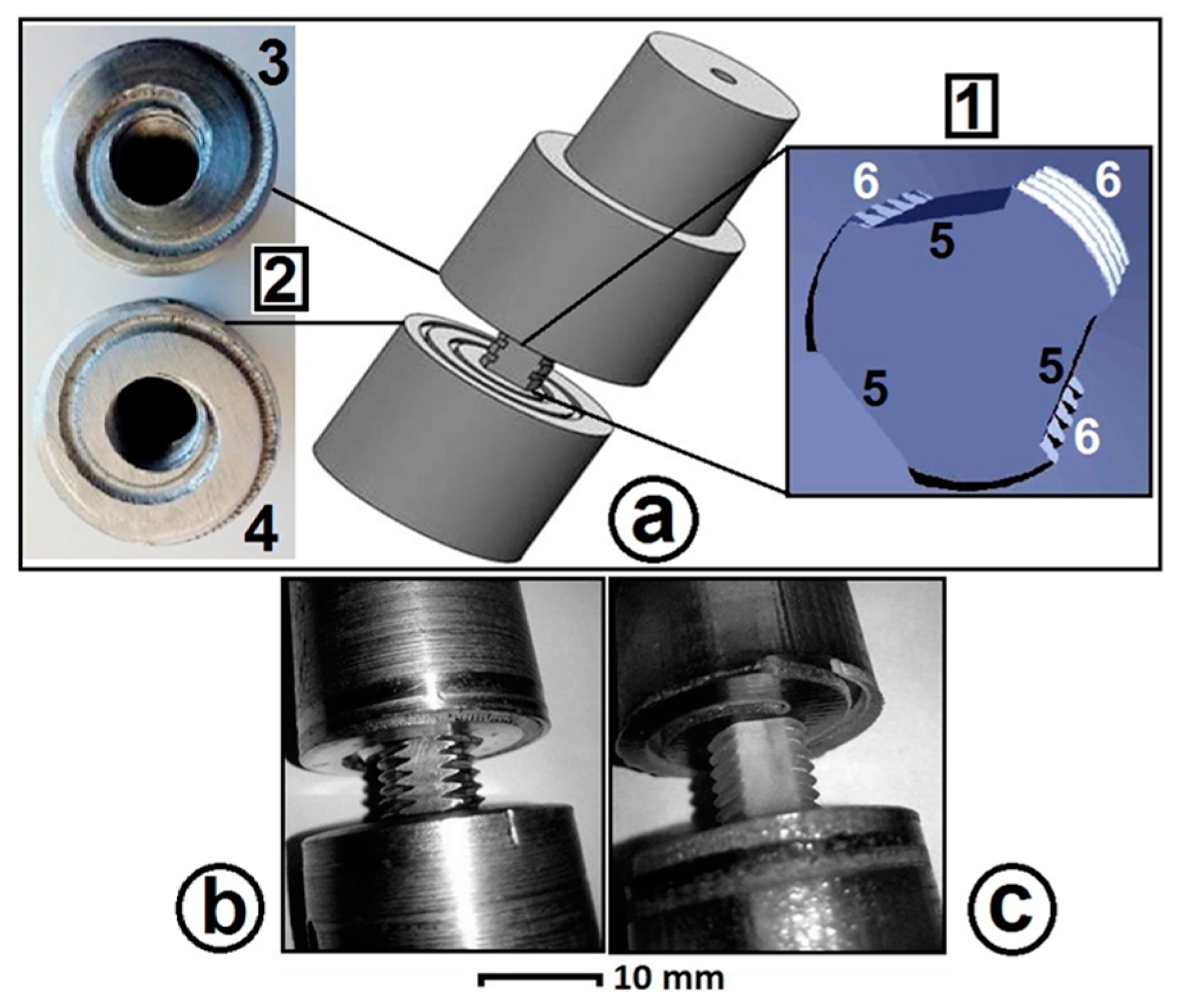
A full-feature fixed bobbin tool as per [18] was used. This comprised a pin with three flats and a thread, along with top and bottom shoulders having clockwise and counter clockwise scrolls, (Figure 1a). For welding of the 100 HV hardness aluminium plates the tool was manufactured from H13 tool steel with hardness 560 HV (Figure 1b). For softer plasticine the tool was economically made of additive manufactured Stratasys VeroClearTM material (Stratasys Connex 3D Printer, Eden Prairie, MN, USA) having no post-processing, Figure 1c.
The pin features were three symmetrical flat surfaces machined onto a screw threaded shaft. The thread provides a better stirring [36]. The flat features allow a vertical flow around the pin to prevent the threads from clogging while stirring the material [36]. A 360 degree spiral pattern was inscribed on each of the shoulder surfaces, with the design intent being that the mouth of the spiral (on the outside edge) would capture substrate material and feed in inwards to the weld region. Alternatively this may be considered a dynamic seal resisting material escaping as flash from the weld. These spirals have opposite hands so that the upper and lower shoulders, which are rigidly connected, engaged in similar relative motion to their respective surfaces.
These started from the edge of the shoulders and ended in the vicinity of the pin location. Direction of the scrolls compared with the tool rotation provides a circulation towards the centre. Threads and flats on the pin and scrolls on shoulders improves the stirring by driving the lateral motion and pumping of material inwards, this avoids spilling [18]. For a stable preservation of stirred material under the shoulder, the diameter (D) ratio (DShoulder/DPin) and compression ratio (difference between biting gap of the bobbin tool and thickness of the workpiece plate) were 5:1 and 3.75%, respectively [37]. Table 1 shows more complete details of the bobbin-tool for the plasticine and aluminium tests.
2.2. Welding Process Parameters
The BFSW processes were compared between actual welds of 6 mm thick AA6082-T6 Al alloy plates with the weld of slabs of 10 mm thick plasticine. The features of the tools were the same, but the shoulder gap differs to accommodate the different substrate thicknesses. 6 mm plasticine slab thickness was tested, but it did not have enough strength to prevent slumping under self-weight at room temperature. Alternatively, it was considered an increase in thickness of the plasticine slabs with a lower work temperature would provide sufficient consolidation for the analogue samples.
A compression ratio of 3.75% was selected for both materials, based on [14,15,17,37]. Compared with CFSW, a degree of compression assists the flow during the BFSW where the downward axial force of CFSW is removed [11]. 3.75% compression ratio for plate thickness less than 10 mm can create sufficient shoulder forging force during the stirring process and also prevent the ejection (spilling) of the material in the form of flash defects [14,37].
The welding parameters (feed rate and rotating speed) were different for the two substrates. The feed and speed range for aluminium were selected based on the works of [14,15,17,37]. For the analogue tests, the feed and speed were selected based on the minimum speed sufficient to create bonding. Because of considerably lower mechanical strength of the plasticine compared with metals, the analogue samples are only applicable for flow visualization. The process parameters for the plasticine analogues were sufficient to provide a high quality joint and to reveal the flow paths. Although the initial purpose of the research was to perform several sets of dynamic variables for the analogue model, the plasticine was unable to be welded at speed and feed much above the slowest parameters of the milling machine available (ω = 75 rpm, V = 50 mm/min) hence only this one set of processes parameters were used here.
We used ω = 400 rpm & V = 350 mm/min as the minimum speeds required to create a weld bond with a tunnel defect in aluminium, and hence comparable to the defect structure observed in plasticine. Lower speeds in this aluminium did not result in a bonded weld, and higher speeds resulted in better welds (with fewer or less extensive defects).
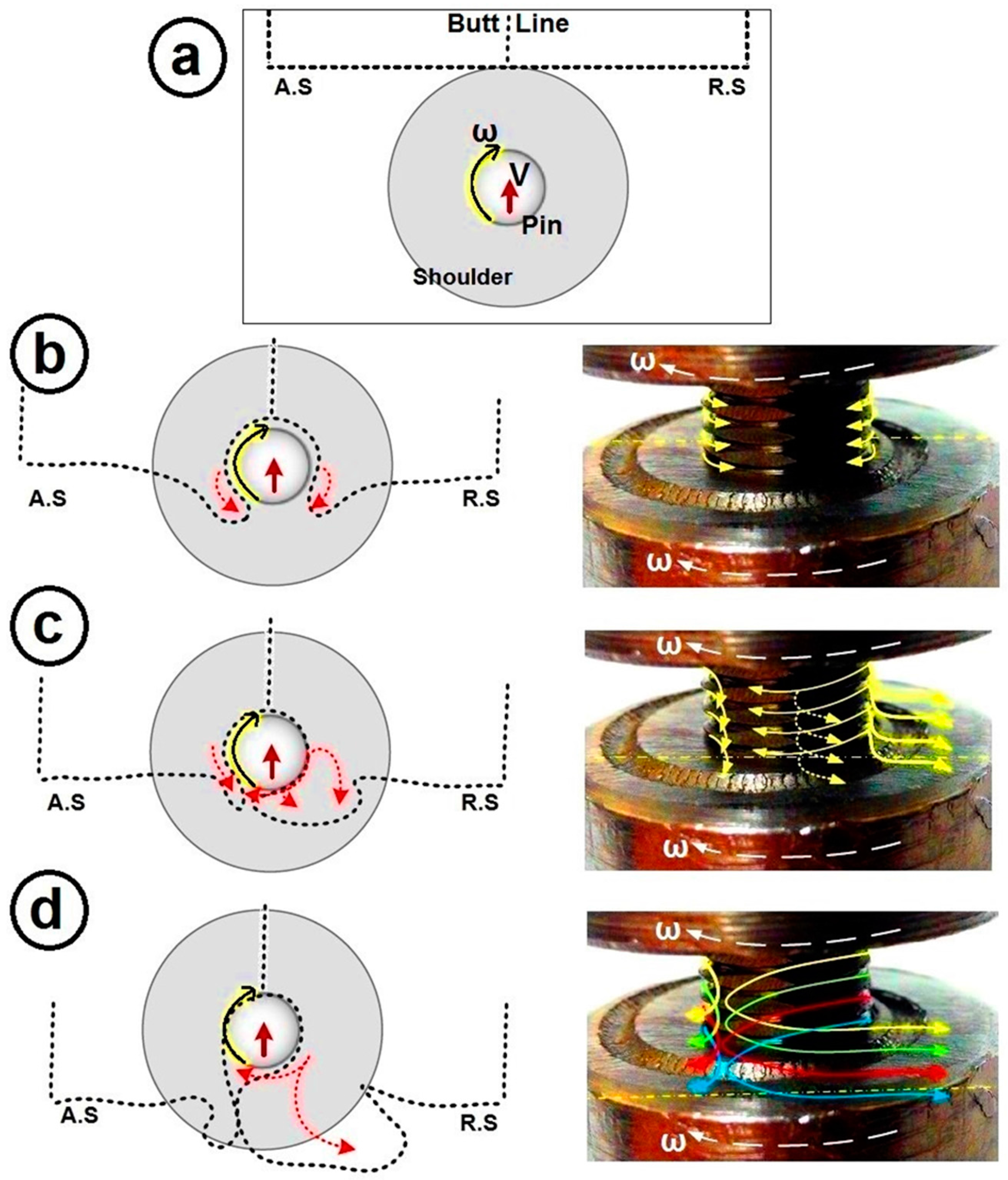
The orientations are designated as follows. The substrate material is laid flat. The origin is at the centre of the tool axis at the intersection with the plane of the upper surface of the substrate. The x-axis is in the direction of feed V hence also the locus of the weld line. The y-axis is in the plane of the substrate and perpendicular to the locus. Positive y is towards the true-right (on the right when viewing when watching the tool from behind) and the rotation convention also makes this the retreating side. The z-axis is downward into the plane of the substrate. The tool rotation ω is designated clockwise when viewed from above. This means that the advancing side (A.S) is on the true-left of the locus (−y) and the retreating side (R.S) is on the true-right (+y).
For ease of interpretation we always (unless stated otherwise) present plan views with the x-axis upwards on the page, i.e., weld entry at bottom of the image. Consequently when viewing the top surface the A.S is consistently on the left, and the R.S on the right, see for example Figures 4, 6a, 7 and 9 (stipulated in Section 3: Results). When viewing the bottom surface the A.S is on the left and the R.S on the right, see Figures 6b and 9 (stipulated in Section 3: Results).
2.3. Methods for Conducting Plasticine Tests
2.3.1. Creating a Layered Plasticine Slab
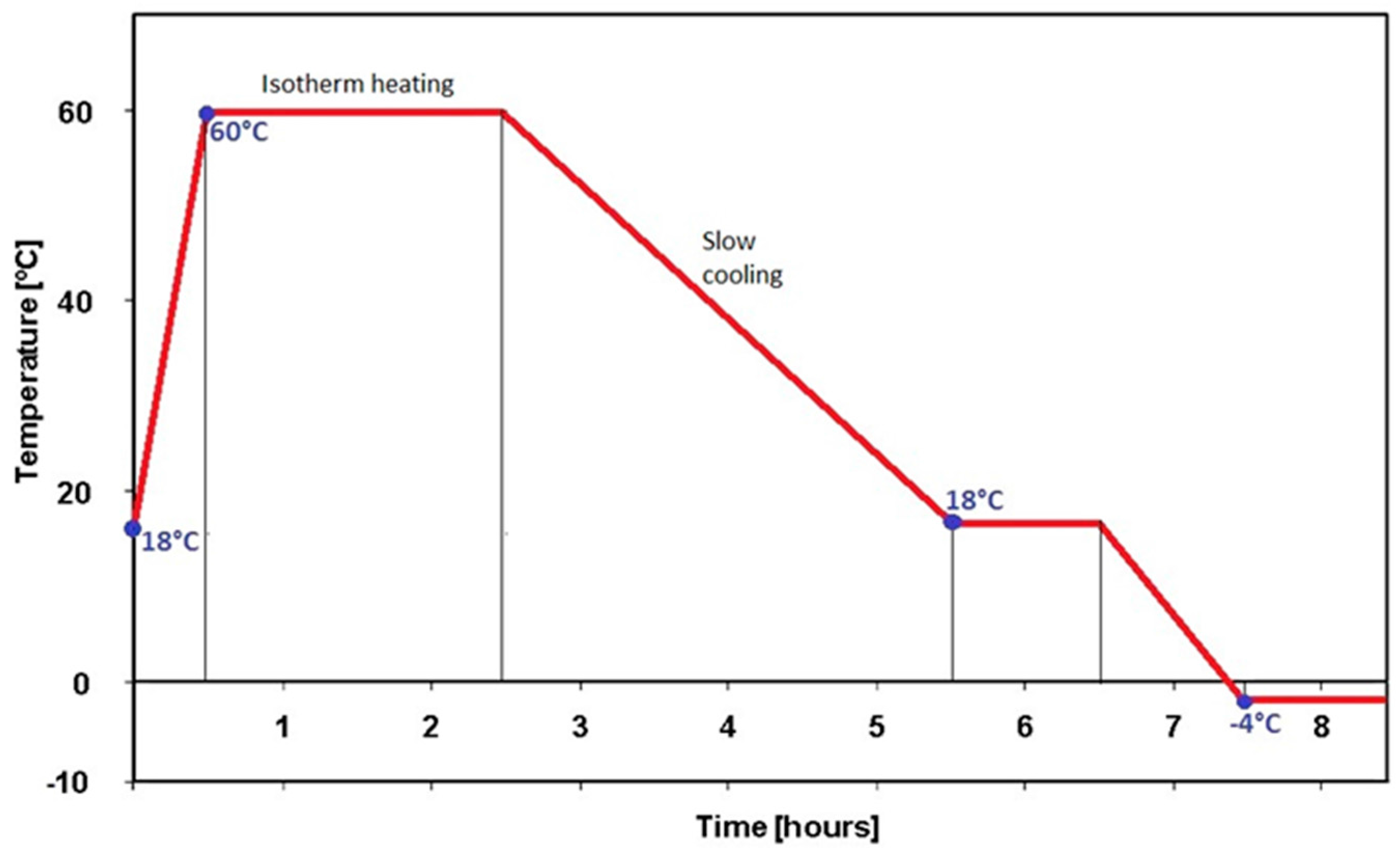
In order to create a multi-layered plasticine block, different colours of the non-drying ‘Newplast’ plasticine manufactured by (Gordon Harris Ltd., London, UK) were used. Since the ‘Newplast’ clay is sufficiently pliable and the rheology firm enough to retain its shape indefinitely, it is widely used for stop-motion clay animation (claymation), therefore it can freeze the flow patterns of the process similar to the actual metal workpiece. To prepare the multi-layered slabs, different colours of plasticine were manually rolled to a uniform thickness of approximately 2.5 mm and then stacked to attain a thickness of 10 mm. These stacked layers were cut by a knife of 0.2 mm thickness to slabs 100 mm (length) × 30 mm (width). They were set for a butt joint configuration producing a welded plate of approximate 100 mm (length) × 60 mm (width). In all the steps of rolling, cutting and welding, glycerin was used as the lubricant. For a reliable analogue model, the multi-colour layers should remain consolidated to avoid delamination during the BFSW process. Therefore, the plasticine blocks were subject to heat treatment to improve the adhesiveness between the layers and also to absorb the excess glycerin between the layers. The melting point of the ‘Newplast’ plasticine was measured to be 87 °C. For the heat treatment, the blocks were heated to 60 °C (>>2/3Tm) and held for a period of three hours using a Nabertherm N20/HR oven (Nabertherm GmbH, Lilienthal, Germany). The heating and cooling rates of the oven were 1.5 °C/min and 0.35 °C/min, respectively. The heat treatment cycle is shown in Figure 2.
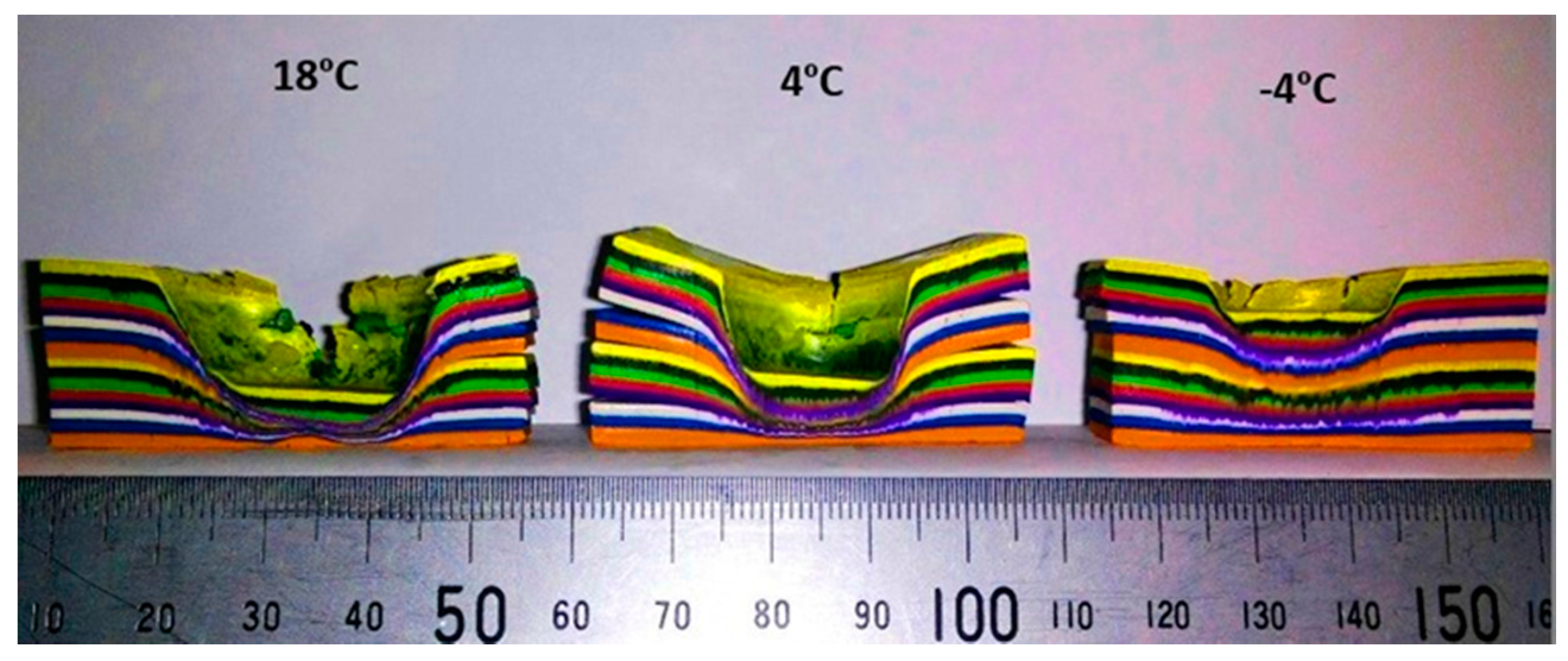
To achieve the most suitable working properties of the plasticine, various methods were assessed including adding fillers and reinforcement. It was found that the most appropriate option was to perform the weld with the plasticine chilled [37]. To find the most suitable temperature for flow visualization a trial forging test was performed on the multi-layered plasticine blocks at three different temperatures, 18 °C, 4 °C and −4 °C. Cross sections of the internal flow results of the forged trials are shown in Figure 3. By considering the melting temperature of the plasticine, the working temperatures were chosen to be much lower to preserve the stability of the sample. Also it should be taken into consideration that during the process the temperature of the sample will increase. For the same force and loading time, severe deformation was shown of the 18 °C block and the deformation made it difficult for flow visualization. Compared to the 4 °C sample, the −4 °C sample left an undisturbed dead zone beside the plasticized region of shear fields. For good quality material flow visualization during a FSW process, we need the flow path lines be distinguishable from the dead zone, hence −4 °C was chosen. This temperature also benefited the resistance to delamination or tearing.
2.3.2. Conducting Tests with Plasticine
Rotating speed ω (75 rpm) and feed velocity V (50 mm/min) were determined by conducting a series of tests to show the formation of a stable weld-line. The plasticine weld samples were run using a manual milling machine (MX-45VAE Model, OKUMA brand, Nagoya, Japan) with motorised longitudinal feed. The slabs for the analogue model of the weld were rigidly fixed between clamp bars and care was taken to ensure that no lateral movement during the welding process occurred. The scroll features on the surface of the shoulders were clockwise and anticlockwise for the upper and lower shoulders, respectively with relation to the direction of the tool rotation. More details of the welding process for the analogue plasticine are shown in Table 1.
2.4. Methods for Conducting Aluminium Tests
For the comparison of the analogue model with the real weld, 6 mm thick of AA6082-T6 aluminium plates were cut to 250 mm (length) × 75 mm (width) per piece and set for a butt joint configuration. Since the aim of the research was to evaluate the evolution of the weld in comparison with the analogue model of the bonding layer, a variety of rotating speed ω (400–650 rpm) and feed rate V (350–400 mm/min) were conducted to validate the joining process. There was no preheating or post-weld processing for the BFSW welded aluminium plates. Table 1 shows more details of welding operation for the aluminium samples.
The aluminium weld trials were conducted on a 3-axis CNC machining centre (2000 Richmond VMC Model, 600 Group brand, Sydney, Australia) with a Fanuc control unit and 14-horsepower spindle motor capacity. The direction of tool rotation was clockwise, as per the analogue tests. The plates were held by strap clamps and supported at the outer faces to be sufficiently rigid.
2.5. Characterization Methods
The weld characteristics and striation flow patterns of the entry and exit defects were examined using conventional fractography techniques for both the plasticine analogue and aluminium welds. For consistency of the visual observations, all photographs were recorded using a high resolution bridge digital camera (FinePix S9500 Model, Fujifilm brand, Tokyo, Japan). To avoid having any shadows on the concave surfaces the photographs were taken under two fluorescent lamps.
3. Results
3.1. General Appearances of the BFSW Weld
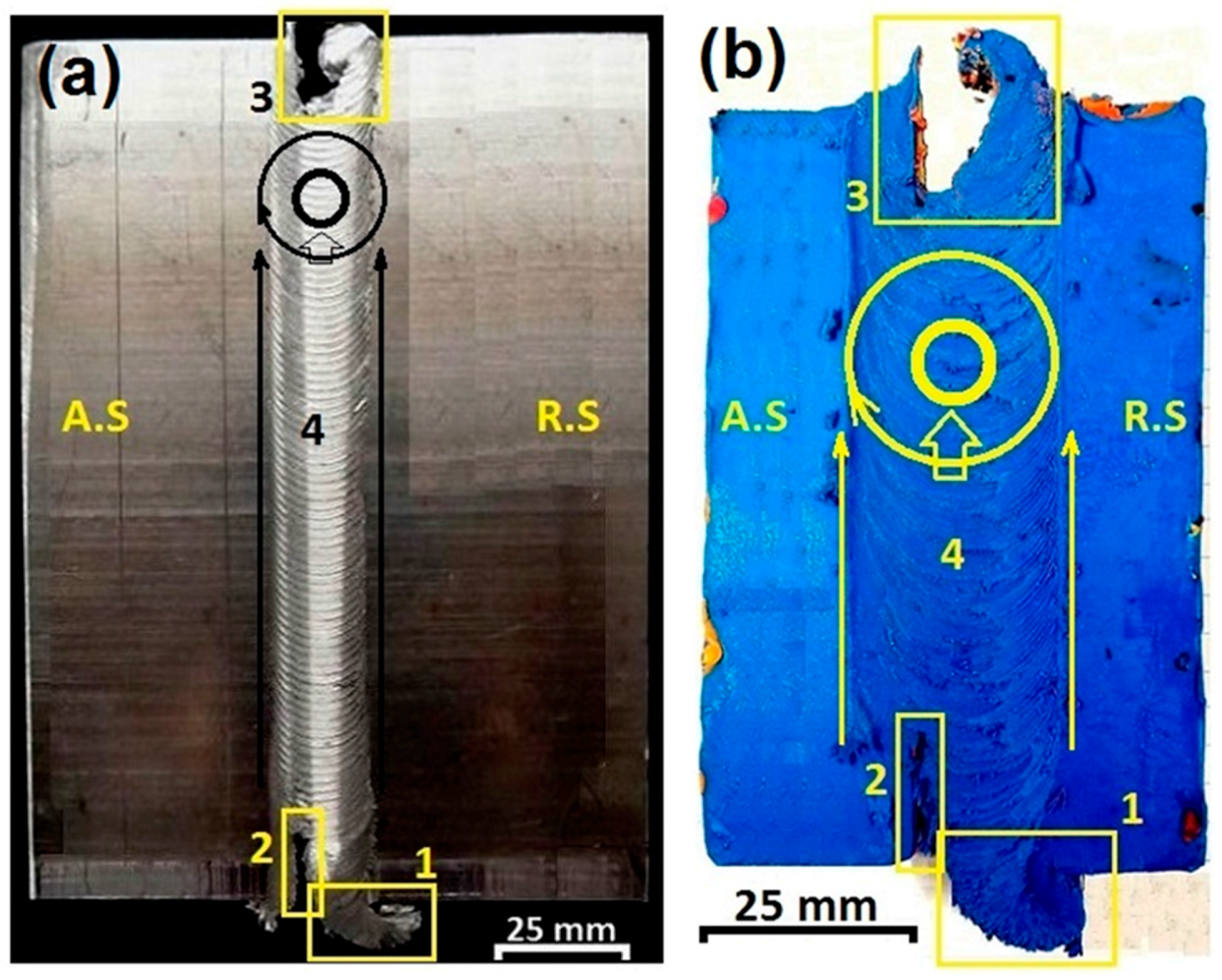
The similarities between the analogue plasticine model and the aluminium welds are revealed in Figure 4 showing the material flow features of the entry and exit zones. The photographs were taken from the top surface of the weld samples (spindle side). The entry defect consists of a distinctive ejected tail (region 1), protruded from the retreating side (R.S) and an adjacent discontinuity (region 2) penetrating the advancing side (A.S) of the weld-line. The exit zone (region 3) shows a keyhole feature where the tool leaves the workpiece. The direction of the tool rotation relative to the weld-line is shown by two concentric circles representative of the shoulder (outer circle) and the pin (inner circle). The weld (region 4) is located in between the entry and exit zones. There is a similarity of size of the entry spray and the exit hole, indicating a similar amount of material is lost from the entry zone and the exit zone.
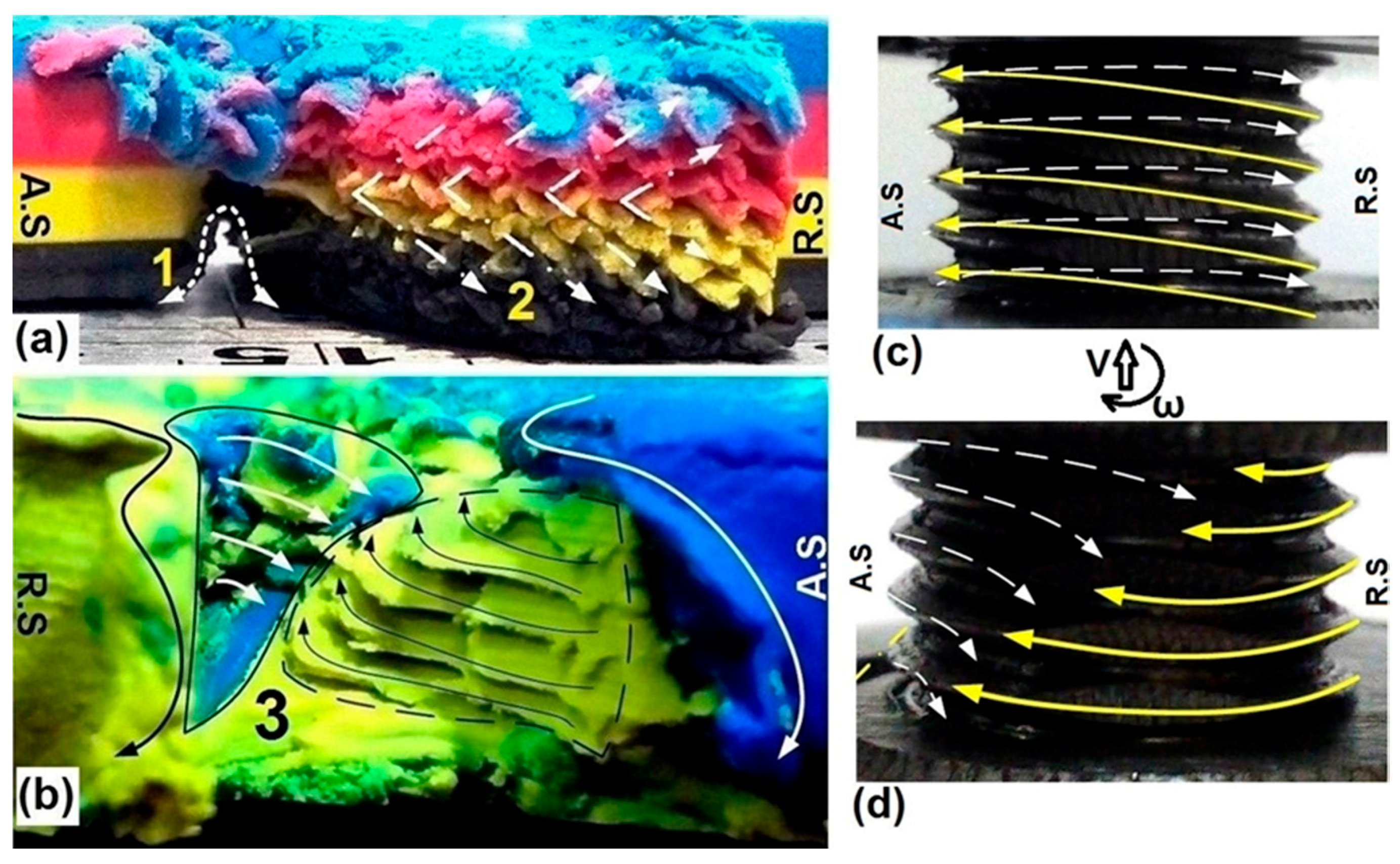
More significant footprints of the shear layers in the formation of the entry and exit zone defects are highlighted in Figure 5. The trace of threads during rotation and movement of the pin are demonstrated in Figure 5a,b for the entry and exit zones, respectively. Also, a corresponding schematic of the shear flow around the pin is drawn in Figure 5c,d. Regarding the entry zone (Figure 5a,c) the thread marks have an intersecting layout which is stretched on a convex face from the A.S to the R.S. The arrangement of diagonal lines of the thread marks from the middle outwards also shows the simultaneous effects of the pin and shoulders on plastic deformation. Another problem in the entry zone Figure 5a is the channeling discontinuity line close to the position of the bottom shoulder which can be recognized as the elementary step of the tunnel void formation. Tunnel void is a visible macro-size defect of the FSW process, resulting in a large discontinuity running along the weld-line occurring on the surface or subsurface [38,39]. There is no solid theory to explain the formation mechanism of the tunnel void. However, it has been suggested that some flow based problems during the process, such as improper plunge of the pin or ineffective stirring between the A.S and the R.S, can generate a nonbonding region in the weld structure [26].
At the end of the weld-line, the rotating pin leaves a concave curve at the exit zone location. As the Figure 5b,d show, the thread traces are again clear in the form of shear flow patterns. As the pin leaves the workpiece, the intensification of the laminar shear stresses around the pin causes a disruption in the efficient flow circulating between the A.S and the R.S [40], consequently the joining bond has failed.
At this stage, because of the different position and shape of the entry and exit defects it seems that the formation mechanisms of them differ, thus they will be discussed separately.
3.2. Entry Zone
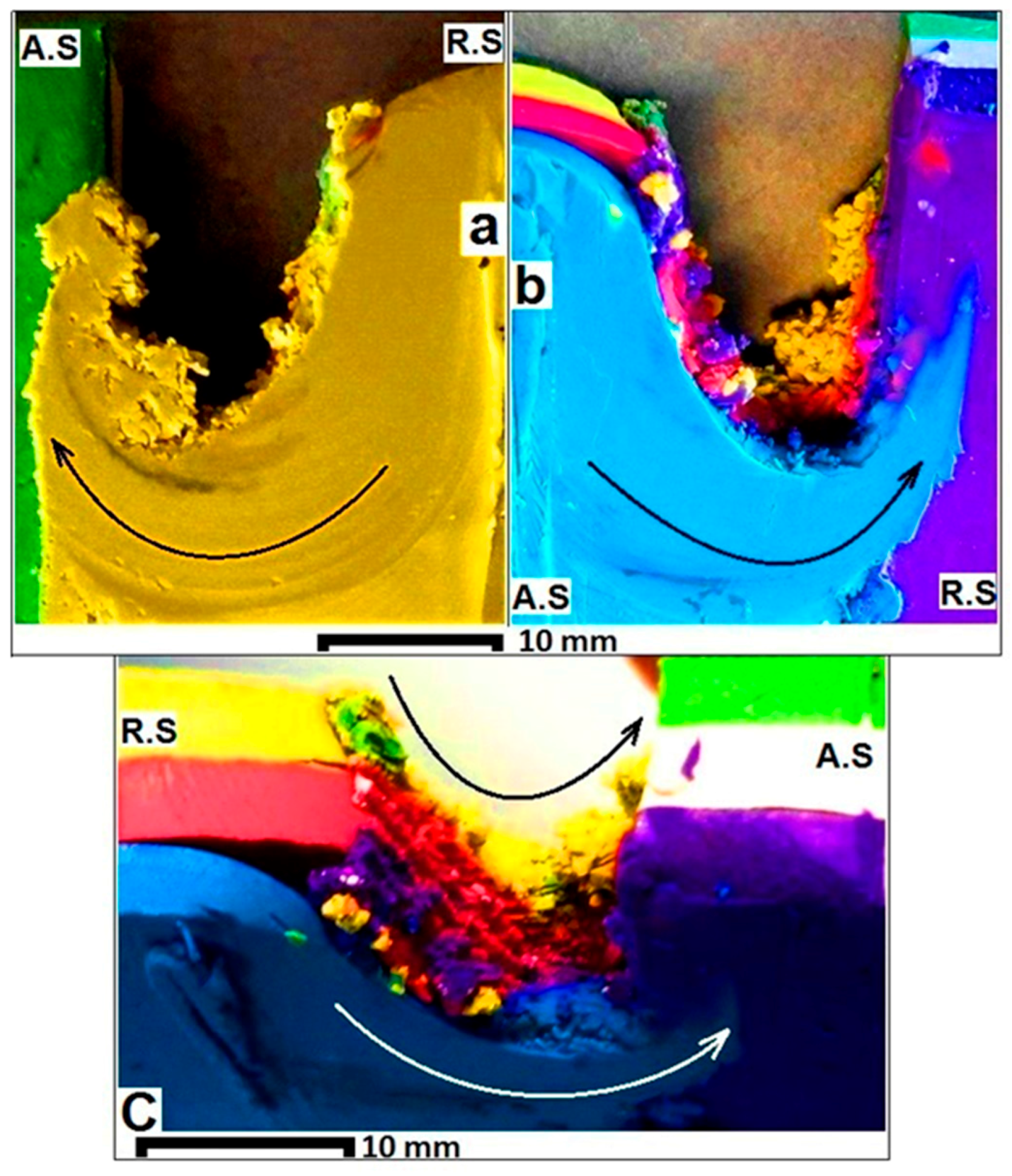
Figure 6 shows the top surface (Figure 6a) and bottom surface (Figure 6b) of the entry zone for a plasticine sample. It is clear the colour of the entry spray on both top and bottom surfaces is the same colour of the R.S material top and bottom layers respectively. As one of the principles of the FSW theory it has been assumed that the joining bond is a result of a mutual material flow circulation from the A.S to the R.S and simultaneously the R.S to the A.S [41,42]. This shows for the fixed-bobbin tool FSW process the early steps of the bobbin tool entering the workpiece the material flow from the R.S to the A.S is disrupted and the plasticized mass flows outwards of the workpiece. The main reason for the material ejection in the entry zone can be attributed to the free surface at the trailing edge of the tool and absence of a solidified mass blocking the flow.
Beside the sprayed tail, there is an island zone laterally deflected to the advancing side with a granular appearance. This region has a smaller amount of shredded material which is picked up by the tool and transferred to the advancing side. The material colour of the mass reveals that the island region came from the A.S layers. Therefore this island is formed by slipping of the A.S mass as the tool enters into the workpiece, or is the result of a successful circulation of the mass from the A.S to the R.S, and simultaneously from the R.S to the A.S.
As it is shown in Figure 6b, the bottom surface of the analogue model, the tunnel void has formed a continuous channel pattern. It starts from the entry zone and extends along the side of weld-line, offset by approximately half of the pin diameter toward the advancing side. Here, the underside channel discontinuity is located at the typical position found for aluminium [43,44,45]. In the structure of FSW welds, complexity of the material flow fields at the triple junction causes a condition for promoting the localized discontinuity defects such as tunnel void or macro-channel [43,44,45]. Sometimes this disarrangement can reach the surface as seen in Figure 6b, but mostly it is observed as a macro-size internal defect.
The analogue model of the BFSW joint shows the tunnel defect emerging with a scouring action on the bottom surface of the substrate (Figure 6b). As a starting hypothesis, the scour region can be the outcome of flow eddies where the linear and rotation motions are combined during the transportation mechanism. However, for a better explanation of the scoured area, study of the flow field around the tool is required. The occurrence of the scour region will be explained in more depth after presenting the metal trial results; this provides a robust comparative observation of scouring features between plasticine and aluminium samples.
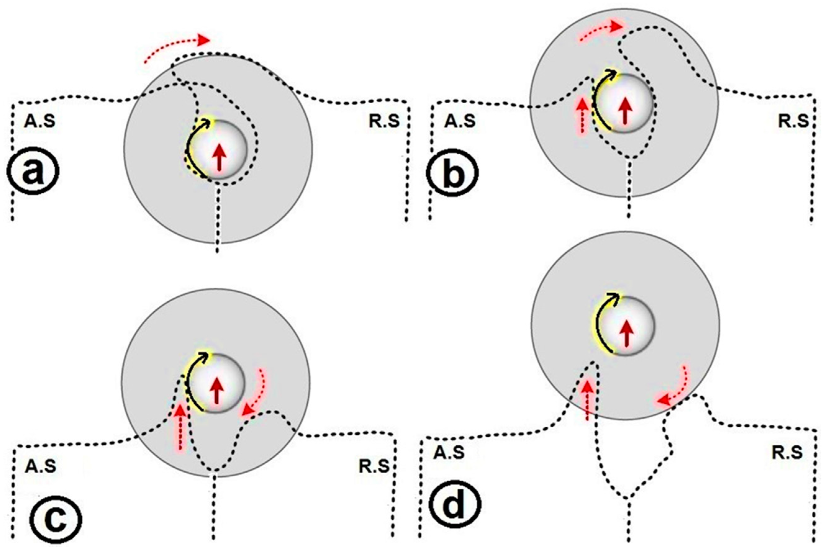
Figure 7 shows the material flow behaviour in the formation of the entry zone with the ejected sprayed tail, the island zone and a nonbonding discontinuity. In general, the entry defect can be characterized as a disordering of the plastic deformation which stabilises as the tool travels completely into the plate. This effect occurs when the shoulders and pin start to engage with the material, but the tool is not fully surrounded by solid material. In this condition, as the rear side of the tool is open, the material is not stirred but instead ejected to the trailing edge where it finally forms a sprayed tail at the free edge of the entry.
Figure 7a shows the schematic of the tool position relative to the A.S and the R.S, with rotating and longitudinal (ω and V) relative to workpiece. According to the Figure 7b, as the tool enters through the substrate it ejects the ploughed material towards the trailing edge, both at the advancing side and the retreating side. It is shown in Figure 7c, the tool is now inside the workpiece and completely surrounded by the plasticized mass. Since the stirring process has not been completely formed yet, some branching patterns are indicated by dotted arrow-lines for the plastic flow around the pin. As the position of the pin is stable inside of the workpiece (Figure 7d) the entry zone has been formed completely and the tool keeps going forward through the workpiece. Passing of the tool from the entry zone, the weld track will be formed along the butt line by the typical stirring flow driven from ω and V.
During the stirring process, successive layers of plasticized flow rotate in different strain planes which cause different twisting directions. By movement of the pin, each twisting pattern can create striation layers which, after travelling a defined deflection distance, reach a stagnation point (on the AS rearward of the pin). Consequently, the plastic mass becomes immobilized next to the adjacent accumulated layers and settles/builds up in the form of the final sprayed tail (similar to Figure 6a). The consequence of these series of movements and settlements of twisting layers is a stirred zone in the body of the material. Since this branching pattern is affected by movement of the tool, there is a gap between the primary and new position of the striation layers. As illustrated in Figure 7d, at the stirring area in trailing edge of the rotating tool, there is a discontinuity region which indicates the original position of separated materials in A.S before taking part in stirring. In other words, since the mass cannot travel the main route of the stirring, this discontinuity is left as the footprint of the unstable circulation of the plastic flow during the early steps of the stirring process. The ejected spray which is curved back towards the workpiece is the plasticized twisting mass. Gradually as the tool plunges into the workpiece, the deposited material at the trailing edge acts as an entry backing plate for the circulating mass and therefore the tail changes from a curved to a straighter profile in the plan view. The similar region in the A.S (Figure 7d), referred to as the island zone, consists of the mass that did not take part in stirring (remained from the primary embedment of the pin into workpiece) or the twisting layers which have strayed away during the stirring cycles.
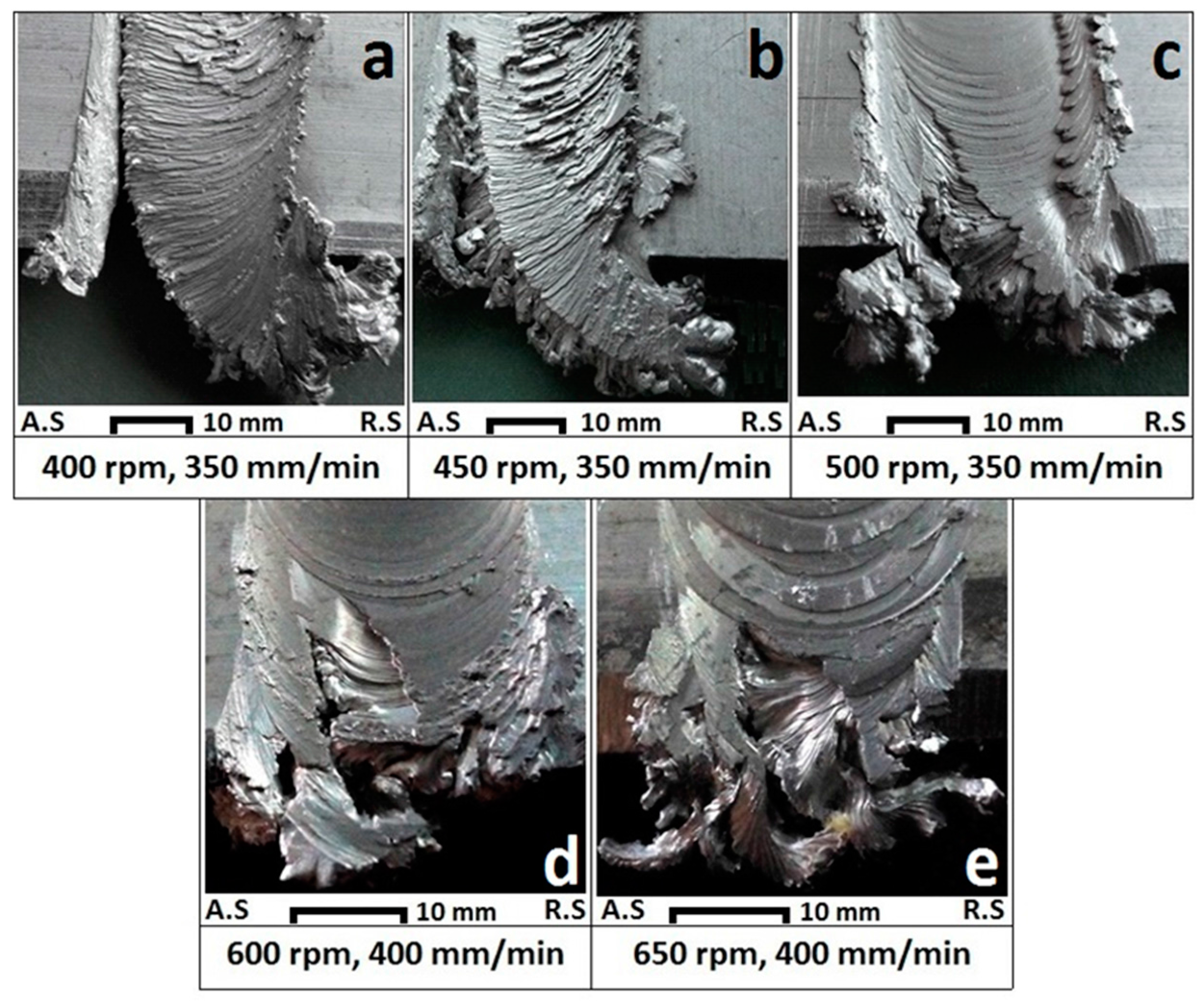
Figure 8 and Figure 9 show the top view and bottom view of the entry zone for aluminium plates in different rotating and longitudinal speeds (ω and V), respectively. These weld tests were performed to investigate the material flow details in the entry and exit zones. For AA6082-T6 plates with 6 mm thickness, the minimum ω and V for creating a join was 400 rpm and 350 mm/min, respectively. Generally, by increasing ω and V, the volume of ejected spray and length of the discontinuity line were decreased, but there was also an increase in the size of the shredded island zone (Figure 8 and Figure 9). At (ω = 500 rpm) and (V = 350 mm/min) the entry spray and discontinuity defect size was minimised. As ω and V are increasing, the volume of the ejected spray decreases on the R.S, but a multi-branched pattern of the spray started to grow in the A.S with a further increasing size of the discontinuity line.
In Figure 8 and Figure 9, images a–c are for feed V = 350 mm/min and the rotation speed ω was varied from 400 rpm to 500 rpm. At rotation speeds higher than 500 rpm the size of the shredded particles at the entry zone was increased and the weld was not formed, hence this was deemed a non-viable process setting. The common practice in these situations is to compensate by increasing the feed, on the basis that heat input is increased by faster rotation speed but decreased by faster feed speed. Hence images d–e are for feed V = 400 mm/min and the rotation speed ω was varied from 600 rpm to 650 rpm.
Thus, increase of speed alone does not eliminate the entry defect, only by an optimum combination of ω and V can the size of the entry defect be minimized.
Regarding the scour region, in Figure 8a,b, also Figure 9a–c, this flow feature exists on the edge of the tunnel void channel for both the aluminium and plasticine samples. The scour region on samples (400 rpm, 350 mm/min) and (450 rpm, 350 mm/min) is evident on the surface. Figure 10 shows the scoured channel discontinuity for aluminium and the analogue plasticine.
The scour region results from the dynamic interaction between the tool and workpiece. The ejection of material from the weld zone at entry causes a mass deficit to persist further along the weld locus. This mass deficit appears as a continuous void on the bottom surface, because the threaded action of the pin pumps material to the top surface. Hence the deficit appears as a scour. This is progressively closed in as the tool moves forward.
The flow circulation from the R.S towards the A.S at the bottom shoulder transports material to the trailing edge of the tool. Here it is smeared into the void, and progressively fills it in. This results in the formation of the streak-like patterns at the edge of the channel which are stretched onto the bottom surface of the weld.
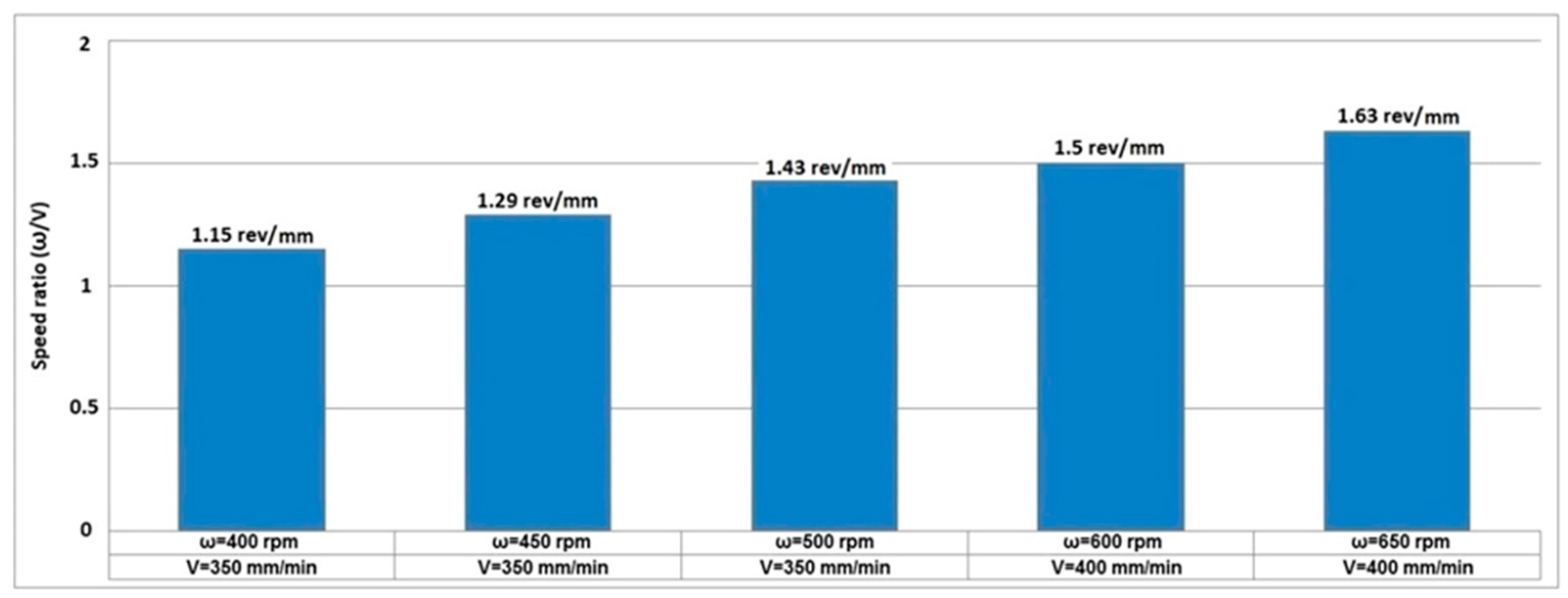
Another variable for BFSW weld quality that has not been considered before is the speed ratio; (rotational speed/feed speed) or (ω/V). The speed ratio is representative of revolutions per tool traverse distance (rev/mm) which can be a key factor for integrity of the flow regimes during the stirring process between the A.S and R.S [31]. An incompatible speed ratio can cause the failure of the weld in the early stages of the process or cause structural defects through the weld-line such as tunnel void or macro-cracks. According to principles of metal forming, plasticizing depends on the heat generated at the contact area between the tool and material [46]. In this situation the tool geometry and the rotational speed of the tool (ω) activate the shear layers required for the plastic deformation. The ω directs the material in a rotational direction, which corresponds to a mutual horizontal flow between A.S and R.S. Differences in ω affect the rate of plasticizing around the tool and also the overall mass flow driven by the stirring [46]. At the same time the longitudinal motion V of the tool creates sufficient working space for transporting the mixed plastic flow behind the pin.
The ratio ω/V has several implications. First, it represents the heat input. Greater heat input is obtained by faster rotation speed ω and decreased feed speed V, i.e., larger values of ω/V. However the relationship between heat and weld quality is not straightforward: greater heat is generally associated with more defects. Rate at which welds are produced, an important consideration in production economics, is determined by feed speed V, hence favours lower ratios of ω/V.
Further considerations arise when considering the entry zone. At the point of entry a high ω/V increases the ejection of material out of the weld zone. The higher ω more violently expels material per images a–c in Figure 8 and Figure 9, including as detached strips and granules that fail to build the adherent structures that limit subsequent ejection. The lower V is presumed to prolong the opportunity for the tool to discharge material. The ejection of material results in a deficit of material in the cross section further along the weld locus, which causes discontinuities in the flow around the tool and in the packing of material.
The packing occurs in the wake of the tool, on the advancing side. The mechanism for this is relatively complex and incompletely understood. Our explanation is that the transport of material around the pin is in batches, with the source material arising from a sector from 9 o’clock (advancing side) to 3 o’clock (retreating side) when viewed from above with 12 o’clock being the x-axis. The batches arise due to the flats on the pin and the slip-stick motion of the tool. The latter occurs to some extent even with smooth pins, is attributed to the dynamic interaction between tool deflection and plasticity in the substrate [15], and is evident in the shoulder marks on the surface (especially those intersecting circlular striation marks that show deviation in tool concentricity). Inside the weld the material is moved in a circular motion (clockwise in the present situation), and deposited in the wake of the tool. The most difficult area to fill is the advancing side near 9 o’clock, because this is where the tool is simultaneously laying down the processed material (from say 7 o’clock to 9 o’clock) and extracting fresh substrate (from 9 o’clock onwards). Microscopy studies show that this is the region where there are many folds of material evident in flow features, and different crystal characteristics [24]. This is also where voids are commonly found. Consequently when finding weld defects in the cross section at the approximate position of the A.S edge of the pin, we attribute these to insufficient material, in turn to loss of material.
Our primary interest here is in the entry feature, but it should be noted that material may be lost in other ways, such as rind/flash, and small chips of material that fall out the bottom of the weld. The greater the material deficit in the weld cross section the greater the defect problem, and in extreme cases a tunnel defect is observed. There is a direct continuation of the scour region (see Figure 9a,b) at entry to the tunnel defect further along the weld locus, and we attribute this to a single underlying mechanisms of loss of material at entry. We attribute the reason for the tunnel defect being at the bottom surface as caused by the threads on the pin, which pump material upwards, see Figure 5.
Loss of material is exacerbated by higher values of ratio ω/V. The different ratios used for the aluminium tests are shown in Figure 11. We were unable to get this grade of aluminium to join at all for ω/V < 1.15 rev/mm. We obtained the best welds (but by no means defect free) towards the centre of this range at ω/V = 1.43 rev/mm. At higher ratios the weld quality deteriorated, as evident in large entry scour and extended tunnel defect.
The ratio of 1.43 rev/mm for aluminium is similar to the speed ratio of 1.5 rev/mm of the plasticine samples (ω = 75 rpm and V = 50 mm/min), and resulted in comparable flow features. This suggests that the formation of the features was determined primarily by geometric mechanisms of flow, rather than material properties or absolute values of welding parameters.
The ratio (ω/V) is effectively a shear rate, where the plasticized mass can flow around the tool in two different frictional modes; sticking contact mode or slipping contact mode [46,47]. An optimum (ω/V) causes a sticking mode when the shear rate is greater than the threshold value to transport the mass crossing from A.S to R.S [46,47,48]. This means that the plastic flow is continuously transported into the stirring region without any local discontinuity of the streamlines—though this is an idealization. In practice the flats on the tool move material in discrete batches. The equilibrium stirring is achieved when material is continuously transported in from A.S to R.S at the front of the tool, and R.S to A.S at the rear. The combined effect of rotation (ω) and longitudinal travelling (V) can cause a transitional sticking/sliding model for the contact mode between the tool and material [49], hence the empirically observed slip-stick motion [15]. The slip-stick causes high frequency dynamic forces in the tool-substrate-machine system, and also explains the striation lines on the outer weld surface (weld crown).
To provide longitudinal conservation of mass across the cross section of the weld, it is necessary for new material to be added to replace that lost at the entry spray. Here in BFSW, the compression ratio for the shoulder gap provides the required make-up material. However the compression is necessarily small due to the stiffness of the substrate, hence it takes some considerable distance of horizontal weld travel before the tunnel defect is closed. Hole-entry avoids the entry spray, hence results in fewer tunnel defects, but has other difficulties due to the need to assemble the tool into the hole. A bobbin tool that is assembled or adjustable tends to have less stiffness than a one-piece tool, and hence greater design challenges.
The material loss is less severe in the CFSW case because the tool may be plunged deeper into the substrate to compensate. Also the CFSW tool may be inclined so as to wedge material into the weld. Furthermore it is competitively simple to start the CFSW process in a drilled hole. All these actions avoid loss of material or increase the amount of material available in the weld region. However for CFSW a large force is required down the axis of the tool to hold it into the material. This is necessary to contain the compressed material within the weld. The single side conventional friction stir welding tool must be provided with this force, whereas the bobbin tool carries the force internally via the pin. Hence tools suitable for hole-entry have benefits and disadvantages.
In summary, we propose that any material lost from the weld cross section is at risk of causing subsequent defects. Consequently one of the key quality issues with BSFW is identified as the need to reduce the loss of material, especially the potentially large volumes of material lost at entry.
3.3. Exit Zone
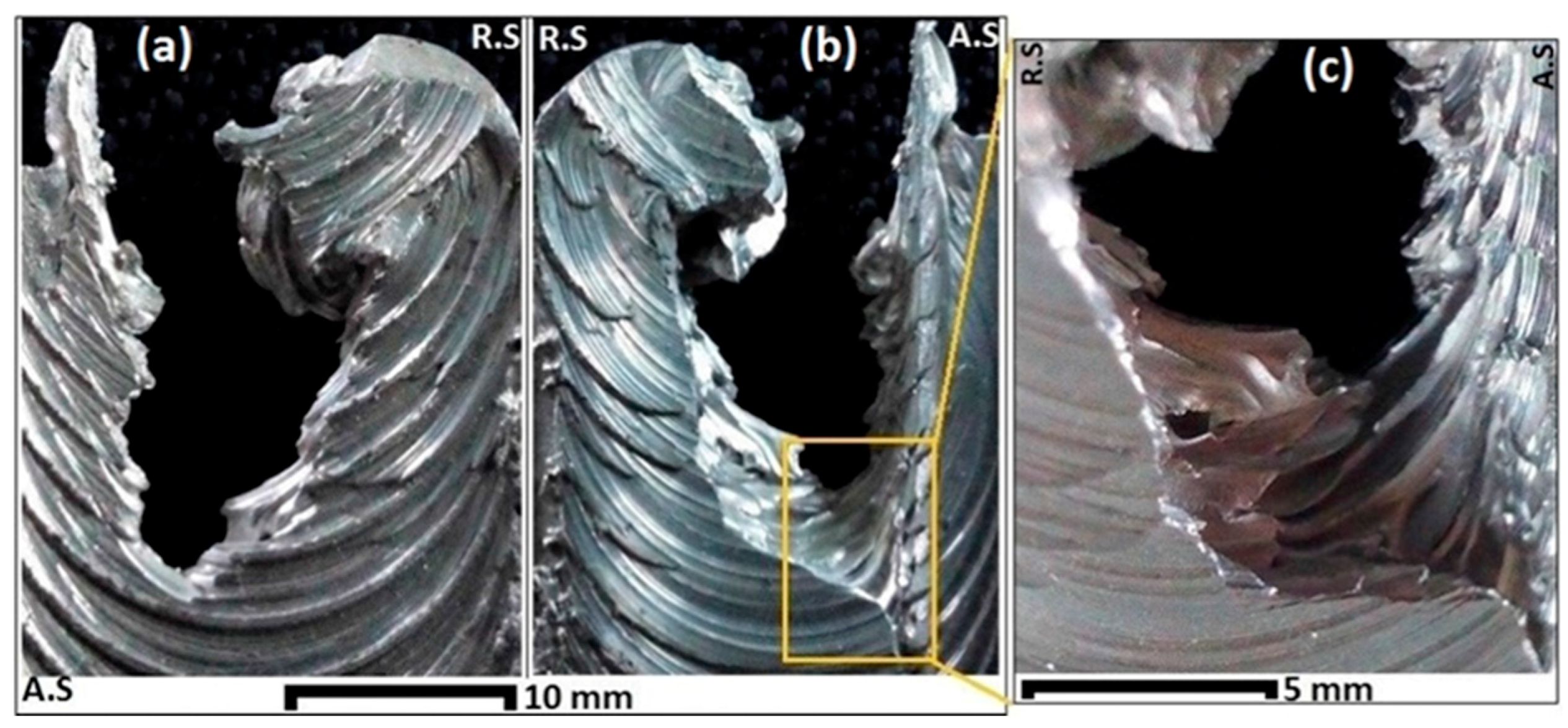
Regarding the exit zone, the aluminium and plasticine welds show similar defect features. Unlike the entry zone, the approximate size of the exit zone did not change by varying ω and V. Figure 12 shows the Top view, Bottom view and Side view of the exit zone for the optimum aluminium weld (ω = 500 rpm, V = 350 mm/min) where the entry defect was minimized. Figure 13 shows the comparable flow features in the exit zone of the analogue model.
Both the aluminium and plasticine welds show similar features at the exit zone, despite different welding parameters.
In both materials the tool leaves the workpiece by a disruption in the body of the weld. The arrows on the top and bottom surfaces of the workpiece (Figure 13a,b) reveal the last trace of the shoulder on the surface in which material is transported from the R.S to the A.S before the start of the disruption, however the circulation system is not able to continue the primary circulation from the A.S to the R.S. The end view (Figure 13c) also shows the shear layers of the exit zone, where the last traces of the pin threads of the tool leaves the material. Figure 13c, similar to Figure 5b, shows a layered pattern in curvature of the side view which is attributed to the threads and flats on the pin and their effect on the plastic flow during the stirring.
The proposed disruption mechanism for the exit zone defect is shown in Figure 14. Starting with Figure 14a, as the material mass in front of the tool loses its stiffness because of the shortage of forward material, the circulation of the material in a path line behind the tool is also irregular. Thus by forward motion of the tool and plastic deformation, the material bulges out and a hole is left behind. In Figure 14b the leading edge of the pin arrives to the free surface and starts to leave the plate. Here, material either side of the tool separates, creating of a wishbone-shaped or keyhole disruption. Figure 14c,d show the exit of the pin and shoulder from the workpiece. For the shown clockwise rotation of the tool, the A.S edge is stretched more than the R.S, and simultaneously the shredded mass in the R.S is compressed back towards the workpiece. As the exit zone is related to the contact mode between the tool and the workpiece, even for different (ω/V) speed ratios the exit disruption will always be present. Therefore, it is confirmed that the exit zone defect is an inherent feature of the process whether we use a simple or complex bobbin tool with different welding parameters.
4. Discussion
4.1. Outcomes
By experiment, it has been shown that plasticine analogue modelling of the BFSW joints can replicate the process and assist with explanation of the flow regimes at the entry and exit defects. Plasticine as a physical analogue can demonstrate reliable flow visualization for the plasticized material during the process [48,50]. The similar formability behaviour of the plasticine to some metals makes it possible to be used for modelling of the shear flow patterns during the severe plastic deformation [29,30]. A plasticine model with multi-coloured layers can reveal the actual flow patterns during the FSW process without needing to prepare and etch metal sections [22,23,24].
The flow visualization findings showed a disruption for the shear bands of the plastic deformation in the boundary layers around the pin. Consequently, the flow interruption can cause the entry and exit defects for the BFSW process. In particular, for the entry defect a change in frictional mode from sticking to slipping during the stirring between the R.S and the A.S can cause the escaping plastic flow from the joint position to the edge of the workpiece, this forms a sprayed tail. The tunnel void discontinuity appeared as a channel at the bottom surface of the weld on the A.S. Although, further characteristics of this defect need to be investigated by observing the internal flow and making and examining cross-sections through the weld. At the exit zone, as the tool approaches the edge of the workpiece, the uniform circulation between the A.S and the R.S is disrupted. As the tool leaves the workpiece, a keyhole-shaped rupture is formed which is the exit defect.
It was found that defects of both the entry and exit zones are inherent features of the BFSW process. The weld trials for AA6082-T6 showed that an optimized speed ratio (ω/V) can minimize the size of these defects.
4.2. Limitations of the Study
As delamination can cause misinterpretation of the flow failure patterns, it would be better if the layered sample had sufficient in-plane resistance to shear stress. This is mitigated by process control during the preparation of the plasticine sample, but this is not always perfectly achieved.
Other limitations relate to representation of heat flow and grain growth. Although plasticine is an amorphous solid it can stay solid after the forming process to duplicate the flow patterns. FSW is a thermo-mechanical process, but because of poor thermal properties of plasticine, study of the thermal history of the weld during the process would be difficult using plasticine analogue modelling. Also, due to the non-metallic and non-crystalline structure of plasticine, study of metallurgical transformation of weld structure, such as microstructure deformation and grain growth is not possible.
4.3. Implications for Future Research
This study was limited to the description of the visual observation of the surface flow features, but more detail can be learnt by examining the internal flow features of cross-sections through the weld. Future work may be directed to extracting cross sections from different locations of the weld zone. These may be useful for studying the material transport and consequently lead to a better understanding of the causes of weld defects.
Another possible line of future investigation could be to make use of analogue modelling to quickly evaluate different process parameters and tool geometry. This is because analogue modelling is faster and quicker than welding aluminium. Also, the cross sections are quick to obtain with analogue modelling, and the colours allow the flow to be immediately revealed, something which is not easily done with aluminium—no combination of etchants can identify the origin of material seen in a cross section.
Another option for further research and flow visualization could be red, green and blue (RGB) colour analysis. This may model the origin of the interlaced materials and the different mass fractions [48].
5. Conclusions
BFSW of AA6082-T6 aluminium plate and corresponding plasticine analogue model were performed to evaluate the features of the entry and exit zones. By varying the rotating and longitudinal tool speed for both of the aluminium and analogue model welds, the entry defect and the exit defect could not be completely eliminated. However, using an optimum rotating and longitudinal tool speed the size of the entry defect can be reduced, although the size and the shape of the exit hole remained similar.
The material flow studies introduced two formation mechanisms for the entry defect and the exit defect. For the entry zone, as the bobbin tool enters into the workpiece from the free-edge of the butt-joint position, the material flow is disrupted from R.S to A.S. Consequently, the plasticized mass flow makes a spray zone outside of the workpiece at the R.S position along with a discontinuity-line at the A.S position of the weld-line.
Existence of the entry and exit defects on the analogue model of the plasticine, and/or in trials with the fully featured tools (threads, flats, scrolls) and in different welding parameters (ω, V) shows that these defects are permanent characteristics of the fixed bobbin-friction stir welding process for edge-entry.
Exiting of the fixed-bobbin tool from the weld line can cause a spontaneous disruption hole due to the lack of material ahead of the pin and dominance of shear flow patterns at the edge of the workpiece and the pin. Accordingly, the bobbin tool leaves the weld-line with a wishbone-shape, referred to as the exit defect.
The research demonstrates that with lowering of the rotating and longitudinal speed of the tool, the multi-layered plasticine analogue model allows visualisation of the plastic flow of the material. Also, it accurately replicates the localized disruption for the positions of the severe plastic deformations in the BFSW process.
Acknowledgments
The authors thank technical staff at the University of Canterbury for assistance with use of facilities, particularly Scott Amies, Eric Cox, Garry Cotton and David Read. Also thanks to Keerthy Chakradhar for assistance with plasticine preparation and testing.
Author Contributions
The analogue model including the fabrication of the plasticine samples and the welding tests were carried out by Abbas Tamadon with the assistance of those acknowledged above. The tool was designed primarily by Kamil Sued with direction from Dirk Pons. The aluminium welding tests were conducted by Kamil Sued. The flow explanations were initially developed by all authors, and finalized by Abbas Tamadon. Abbas Tamadon produced the diagrams of flow patterns and the photographs. Dirk Pons, Kamil Sued, and Don Clucas supervised. The first draft of the paper was written by Abbas Tamadon, major edits by Don Clucas and Dirk Pons. All authors contributed to writing the subsequent drafts.
Conflicts of Interest
The authors declare no conflict of interest.
References
- Thomas, W. Friction Stir Welding. International Patent Application No. PCT/GB92/02203, 6 December 1991. [Google Scholar]
- Arbegast, W.J. A flow-partitioned deformation zone model for defect formation during friction stir welding. Scr. Mater. 2008, 58, 372–376. [Google Scholar] [CrossRef]
- Morisada, Y.; Imaizumi, T.; Fujii, H. Clarification of material flow and defect formation during friction stir welding. Sci. Technol. Weld. Join. 2015, 20, 130–137. [Google Scholar] [CrossRef]
- Waldron, D.; Roberts, R.; Dawes, C.; Tubby, P. Friction Stir Welding-A Revolutionary New Joining Method; SAE Technical Paper; Society of Automotive Engineers: Warrendale, PA, USA, 1998; ISBN 0768005167. [Google Scholar] [CrossRef]
- Zhang, Z.; Zhang, H. Effect of welding parameters on mixing of materials in nugget zone of friction stir welds. Acta Metall. Sin.-Chin. Ed. 2007, 43, 321. [Google Scholar]
- Leonard, A.; Lockyer, S. Flaws in friction stir welds. In Proceedings of the 4th International Symposium on Friction Stir Welding, Park City, UT, USA, 14–16 May 2003. [Google Scholar]
- Leal, R.M.; Loureiro, A. Defects formation in friction stir welding of aluminium alloys. In Materials Science Forum; Trans Tech Publications: Zürich, Switzerland, 2004; pp. 299–302. [Google Scholar]
- Le Jolu, T.; Morgeneyer, T.F.; Denquin, A.; Gourgues-Lorenzon, A.-F. Effect of welding defects on plastic behaviour and fatigue lifetime of friction stir welded Al-Cu-Li alloy. In Proceedings of the 13th International Conference on Fracture, Beijing, China, 16–21 June 2013; p. 10. [Google Scholar]
- Dickerson, T.; Przydatek, J. Fatigue of friction stir welds in aluminium alloys that contain root flaws. Int. J. Fatigue 2003, 25, 1399–1409. [Google Scholar] [CrossRef]
- Threadgill, P.L.; Ahmed, M.; Martin, J.P.; Perrett, J.G.; Wynne, B.P. The use of bobbin tools for friction stir welding of aluminium alloys. In Materials Science Forum; Trans Tech Publications: Zürich, Switzerland, 2010; pp. 1179–1184. [Google Scholar]
- Thomas, W.; Wiesner, C.; Marks, D.; Staines, D. Conventional and bobbin friction stir welding of 12% chromium alloy steel using composite refractory tool materials. Sci. Technol. Weld. Join. 2009, 14, 247–253. [Google Scholar] [CrossRef]
- Martin, J.; Wei, S. Friction stir welding technology for marine applications. In Friction Stir Welding and Processing VIII; Springer: Berlin, Germany, 2015; pp. 219–226. [Google Scholar]
- Neumann, T.; Zettler, R.; Vilaca, P.; Dos Santos, J.; Quintino, L. Analysis of self-reacting friction stir welds in a 2024-T351 alloy. In Friction Stir Welding and Processing IV; The Minerals, Metals & Materials Society: Pittsburgh, PA, USA, 2007; pp. 55–72. [Google Scholar]
- Thomas, W.; Wiesner, C. Recent developments of fsw technologies: Evaluation of root defects, composite refractory tools for steel joining and one-pass welding of thick sections using self-reacting bobbin tools. In Proceedings of the Trends in Welding Research 8th International Conference, Callaway Gardens Resort, Pine Mountain, GA, USA, 1–6 June 2008; ASM International: Almere, The Netherlands, 2009; p. 25. [Google Scholar]
- Sued, M.K.; Pons, D.J. Dynamic interaction between machine, tool, and substrate in bobbin friction stir welding. Int. J. Manuf. Eng. 2016, 2016. [Google Scholar] [CrossRef]
- Chen, J.; Fujii, H.; Sun, Y.; Morisada, Y.; Ueji, R. Fine grained Mg-3Al-1Zn alloy with randomized texture in the double-sided friction stir welded joints. Mater. Sci. Eng. A 2013, 580, 83–91. [Google Scholar] [CrossRef]
- Hejazi, I.; Mirsalehi, S.E. Effect of pin penetration depth on double-sided friction stir welded joints of AA6061-T913 alloy. Trans. Nonferr. Met. Soc. China 2016, 26, 676–683. [Google Scholar] [CrossRef]
- Sued, M.; Pons, D.; Lavroff, J.; Wong, E.-H. Design features for bobbin friction stir welding tools: Development of a conceptual model linking the underlying physics to the production process. Mater. Des. (1980–2015) 2014, 54, 632–643. [Google Scholar] [CrossRef]
- Esmaily, M.; Mortazavi, N.; Osikowicz, W.; Hindsefelt, H.; Svensson, J.; Halvarsson, M.; Martin, J.; Johansson, L. Bobbin and conventional friction stir welding of thick extruded AA6005-T6 profiles. Mater. Des. 2016, 108, 114–125. [Google Scholar] [CrossRef]
- Dolby, R.; Sanderson, A.; Threadgill, P. Recent developments and applications in electron beam and friction technologies. In Proceedings of the 7th International Aachen Welding Conference, Kobe, Japan, 20–22 November 2001. [Google Scholar]
- Sued, M.K. Fixed Bobbin Friction Stir Welding of Marine Grade Aluminium. Ph.D. Thesis, University of Canterbury, Christchurch, New Zealand, 2015. [Google Scholar]
- Zhang, H.; Wang, M.; Zhang, X.; Yang, G. Microstructural characteristics and mechanical properties of bobbin tool friction stir welded 2A14-T6 aluminum alloy. Mater. Des. (1980–2015) 2015, 65, 559–566. [Google Scholar] [CrossRef]
- Shen, J.; Wang, F.; Suhuddin, U.F.; Hu, S.; Li, W.; Dos Santos, J.F. Crystallographic texture in bobbin tool friction-stir-welded aluminum. Metall. Mater. Trans. A 2015, 46, 2809–2813. [Google Scholar] [CrossRef]
- Tamadon, A.; Pons, D.J.; Sued, K.; Clucas, D. Development of metallographic etchants for the microstructure evolution of A6082-T6 BFSW welds. Metals 2017, 7, 423. [Google Scholar] [CrossRef]
- Li, W.; Fu, T.; Hütsch, L.; Hilgert, J.; Wang, F.; Dos Santos, J.; Huber, N. Effects of tool rotational and welding speed on microstructure and mechanical properties of bobbin-tool friction-stir welded Mg AZ31. Mater. Des. 2014, 64, 714–720. [Google Scholar] [CrossRef]
- Sued, M.; Tamadon, A.; Pons, D. Material flow visualization in bobbin friction stir welding by analogue model. In Proceedings of Mechanical Engineering Research Day 2017; Centre for Advanced Research on Energy: Durian Tunggal, Melaka, Malaysia, 2017; pp. 368–369. [Google Scholar]
- Liu, H.; Hou, J.; Guo, H. Effect of welding speed on microstructure and mechanical properties of self-reacting friction stir welded 6061-T6 aluminum alloy. Mater. Des. 2013, 50, 872–878. [Google Scholar] [CrossRef]
- Wan, L.; Huang, Y.; Lv, Z.; Lv, S.; Feng, J. Effect of self-support friction stir welding on microstructure and microhardness of 6082-T6 aluminum alloy joint. Mater. Des. 2014, 55, 197–203. [Google Scholar] [CrossRef]
- Wan, L.; Huang, Y.; Guo, W.; Lv, S.; Feng, J. Mechanical properties and microstructure of 6082-T6 aluminum alloy joints by self-support friction stir welding. J. Mater. Sci. Technol. 2014, 30, 1243–1250. [Google Scholar] [CrossRef]
- He, X.; Gu, F.; Ball, A. A review of numerical analysis of friction stir welding. Prog. Mater. Sci. 2014, 65, 1–66. [Google Scholar] [CrossRef]
- Dialami, N.; Chiumenti, M.; Cervera, M.; de Saracibar, C.A.; Ponthot, J.-P.; Bussetta, P. Numerical simulation and visualization of material flow in friction stir welding via particle tracing. In Numerical Simulations of Coupled Problems in Engineering; Springer: Berlin, Germany, 2014; pp. 157–169. [Google Scholar]
- Buffa, G.; Donati, L.; Fratini, L.; Tomesani, L. Solid state bonding in extrusion and FSW: Process mechanics and analogies. J. Mater. Process. Technol. 2006, 177, 344–347. [Google Scholar] [CrossRef]
- Genevois, C.; Girard, M.; Huneau, B.; Sauvage, X.; Racineux, G. Interfacial reaction during friction stir welding of Al and Cu. Metall. Mater. Trans. A 2011, 42, 2290. [Google Scholar] [CrossRef]
- Hilgert, J.; Schmidt, H.; Dos Santos, J.; Huber, N. Thermal models for bobbin tool friction stir welding. J. Mater. Process. Technol. 2011, 211, 197–204. [Google Scholar] [CrossRef]
- Hilgert, J.; dos Santos, J.F.; Huber, N. Investigation of the material shear layer in bobbin tool friction stir welding. In Friction Stir Welding and Processing VI; Wiley: Hoboken, NJ, USA, 2011; pp. 187–193. [Google Scholar]
- Lin, S.-B.; Zhao, Y.-H.; He, Z.-Q.; Wu, L. Modeling of friction stir welding process for tools design. Front. Mater. Sci. 2011, 5, 236–245. [Google Scholar] [CrossRef]
- Sued, M.; Pons, D.; Lavroff, J. Compression ratio effects in bobbin friction stir welding. In Proceedings of the 10th International Friction Stir Welding Symposium, Beijing, China, 20–22 May 2014; pp. 1–19. [Google Scholar]
- Chouhan, D.; Pal, S.K.; Garg, S. Experimental study on the effect of welding parameters and tool pin profiles on mechanical properties of the FSW joints. Dimensions 2013, 806, 28. [Google Scholar]
- Ragupathy, V.; Bhat, M.; Prasad, M. An experimental study of discontinuities in friction stir welded joints through nondestructive testing. Mater. Eval. 2017, 75, 406–412. [Google Scholar]
- Conti, P.; De Paulis, A. A simple model to simulate the interlaminar stresses generated near the free edge of a composite laminate. In Delamination and Debonding of Materials; ASTM International: Almere, The Netherlands, 1985. [Google Scholar]
- Seidel, T.; Reynolds, A.P. Visualization of the material flow in AA2195 friction-stir welds using a marker insert technique. Metall. Mater. Trans. A 2001, 32, 2879–2884. [Google Scholar] [CrossRef]
- Reynolds, A.P. Flow visualization and simulation in FSW. Scr. Mater. 2008, 58, 338–342. [Google Scholar] [CrossRef]
- Chen, Z.; Pasang, T.; Qi, Y. Shear flow and formation of nugget zone during friction stir welding of aluminium alloy 5083-O. Mater. Sci. Eng. A 2008, 474, 312–316. [Google Scholar] [CrossRef]
- Liu, Z.; Xin, R.; Liu, D.; Shu, X.; Liu, Q. Textural variation in triple junction region of friction stir welded Mg alloys and its influence on twinning and fracture. Mater. Sci. Eng. A 2016, 658, 185–191. [Google Scholar] [CrossRef]
- Liu, D.; Xin, R.; Sun, L.; Zhou, Z.; Liu, Q. Influence of sampling design on tensile properties and fracture behavior of friction stir welded magnesium alloys. Mater. Sci. Eng. A 2013, 576, 207–216. [Google Scholar] [CrossRef]
- Liechty, B.; Webb, B. Modeling the frictional boundary condition in friction stir welding. Int. J. Mach. Tools Manuf. 2008, 48, 1474–1485. [Google Scholar] [CrossRef]
- Liechty, B.; Webb, B. Flow field characterization of friction stir processing using a particle-grid method. J. Mater. Process. Technol. 2008, 208, 431–443. [Google Scholar] [CrossRef]
- Liechty, B.; Webb, B. The use of plasticine as an analog to explore material flow in friction stir welding. J. Mater. Process. Technol. 2007, 184, 240–250. [Google Scholar] [CrossRef]
- Zhu, Z.; Wang, M.; Zhang, H.; Zhang, X.; Yu, T.; Wu, Z. A finite element model to simulate defect formation during friction stir welding. Metals 2017, 7, 256. [Google Scholar] [CrossRef]
- Gratecap, F.; Girard, M.; Marya, S.; Racineux, G. Exploring material flow in friction stir welding: Tool eccentricity and formation of banded structures. Int. J. Mater. Form. 2012, 5, 99–107. [Google Scholar] [CrossRef]
Figure 1.
Schematic of the Bobbin Tool employed in experimental tests, (a) 3D model of the bobbin tool; (1) pin, (2) open end scrolls, (3) top shoulder, (4)bottom shoulder, (5) flats, (6) threads; (b) H13 steel bobbin tool for aluminium; and (c) 3D printed bobbin tool for plasticine.
Figure 1.
Schematic of the Bobbin Tool employed in experimental tests, (a) 3D model of the bobbin tool; (1) pin, (2) open end scrolls, (3) top shoulder, (4)bottom shoulder, (5) flats, (6) threads; (b) H13 steel bobbin tool for aluminium; and (c) 3D printed bobbin tool for plasticine.

Figure 2.
Heat treatment procedure of the multi-layered plasticine slabs.

Figure 3.
Cross section of the internal flow pattern of forging trials for the plasticine samples at 18 °C, 4 °C and −4 °C working temperature.
Figure 3.
Cross section of the internal flow pattern of forging trials for the plasticine samples at 18 °C, 4 °C and −4 °C working temperature.

Figure 4.
Top surface of the weld samples; defect features and the direction of the tool relative to the weld-line, (a) Aluminium plate; and (b) plasticine model; (1) the entry spray, (2) tunnel void discontinuity, (3) the exit zone, (4) weld-line track.
Figure 4.
Top surface of the weld samples; defect features and the direction of the tool relative to the weld-line, (a) Aluminium plate; and (b) plasticine model; (1) the entry spray, (2) tunnel void discontinuity, (3) the exit zone, (4) weld-line track.

Figure 5.
(a) Effect of threads in the entry zone; and (b) the exit zone, replicated in analogue model; (1) tunnel void, (2) schematic of the shear-bands in the entry zone, (3) schematic of the shear-bands in the exit zone; and (c,d) Schematic of the shear flow around the pin for the entry zone and exit zone, respectively.

Figure 6.
The stage of the entry zone, (a) top view, and (b) bottom view.
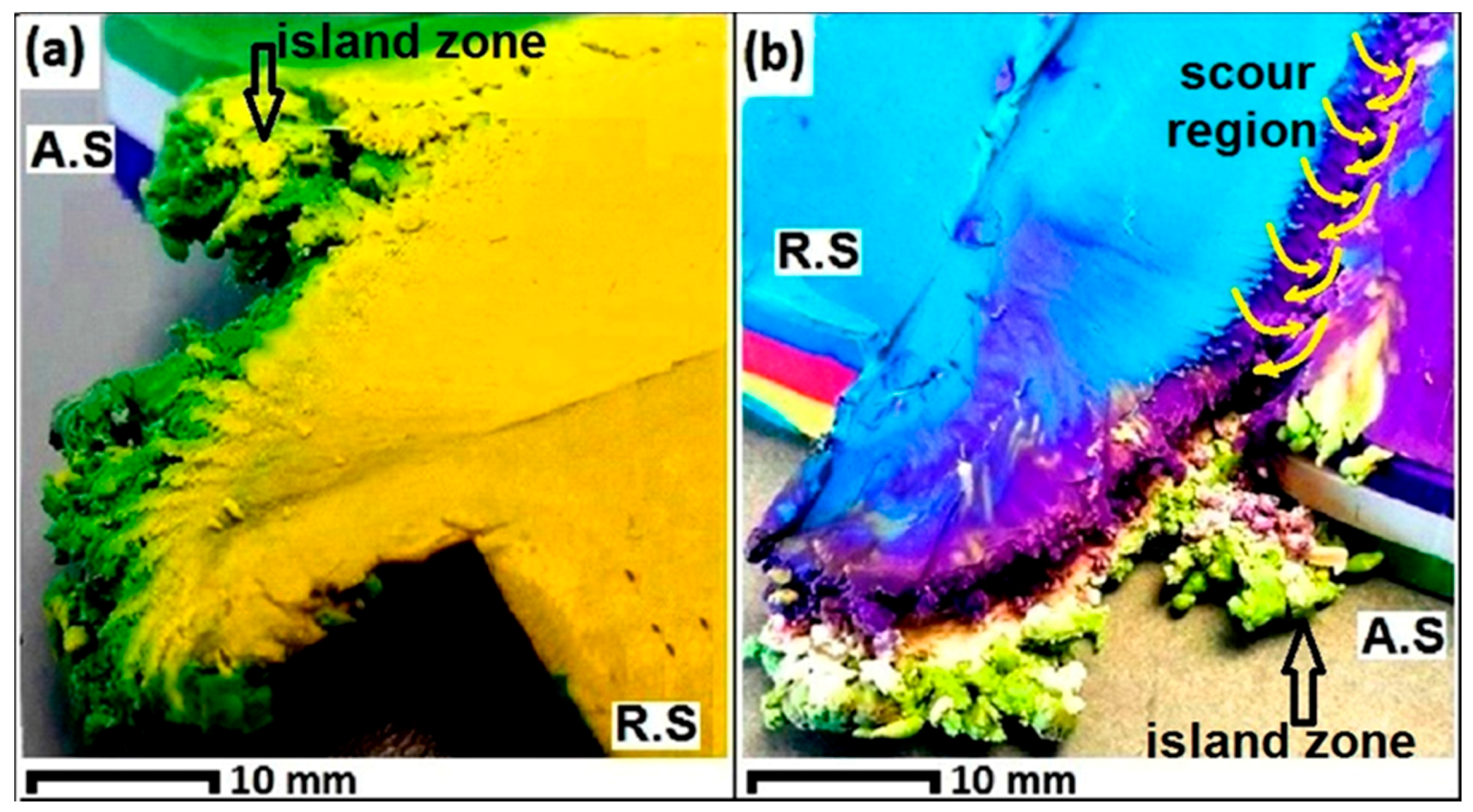
Figure 7.
Schematic of formation of the entry region at the rear of the pin, (a) relative position of the tool and workpiece; (b) initial contact between the rotating tool and workpiece; (c) formation of the ejected spray by rotation of the tool inside the workpiece; and (d) final profile of the mass ejection and formation of the entry defect consisting of a curved tail, island zone and a nonbonding discontinuity (Left: Top view of the tool-workpiece interaction, Right: flow streamlines around the pin profile).

Figure 8.
The entry region (Top view) in different (ω/V) ratios, (a) 400 rpm, 350 mm/min; (b) 450 rpm, 350 mm/min; (c) 500 rpm, 350 mm/min; (d) 600 rpm, 400 mm/min; and (e) 650 rpm, 400 mm/min.
Figure 8.
The entry region (Top view) in different (ω/V) ratios, (a) 400 rpm, 350 mm/min; (b) 450 rpm, 350 mm/min; (c) 500 rpm, 350 mm/min; (d) 600 rpm, 400 mm/min; and (e) 650 rpm, 400 mm/min.

Figure 9.
The entry region (Bottom view) for different (ω/V) ratios, (a) 400 rpm, 350 mm/min; (b) 450 rpm, 350 mm/min; (c) 500 rpm, 350 mm/min; (d) 600 rpm, 400 mm/min; and (e) 650 rpm, 400 mm/min.
Figure 9.
The entry region (Bottom view) for different (ω/V) ratios, (a) 400 rpm, 350 mm/min; (b) 450 rpm, 350 mm/min; (c) 500 rpm, 350 mm/min; (d) 600 rpm, 400 mm/min; and (e) 650 rpm, 400 mm/min.
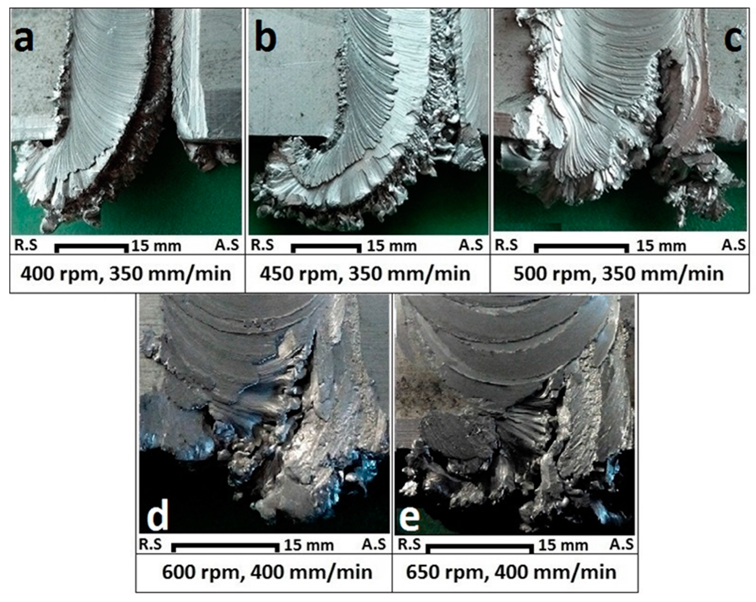
Figure 10.
Schematic of the entry scour region for the channel discontinuity: (a) aluminium weld; and (b) analogue plasticine.
Figure 10.
Schematic of the entry scour region for the channel discontinuity: (a) aluminium weld; and (b) analogue plasticine.
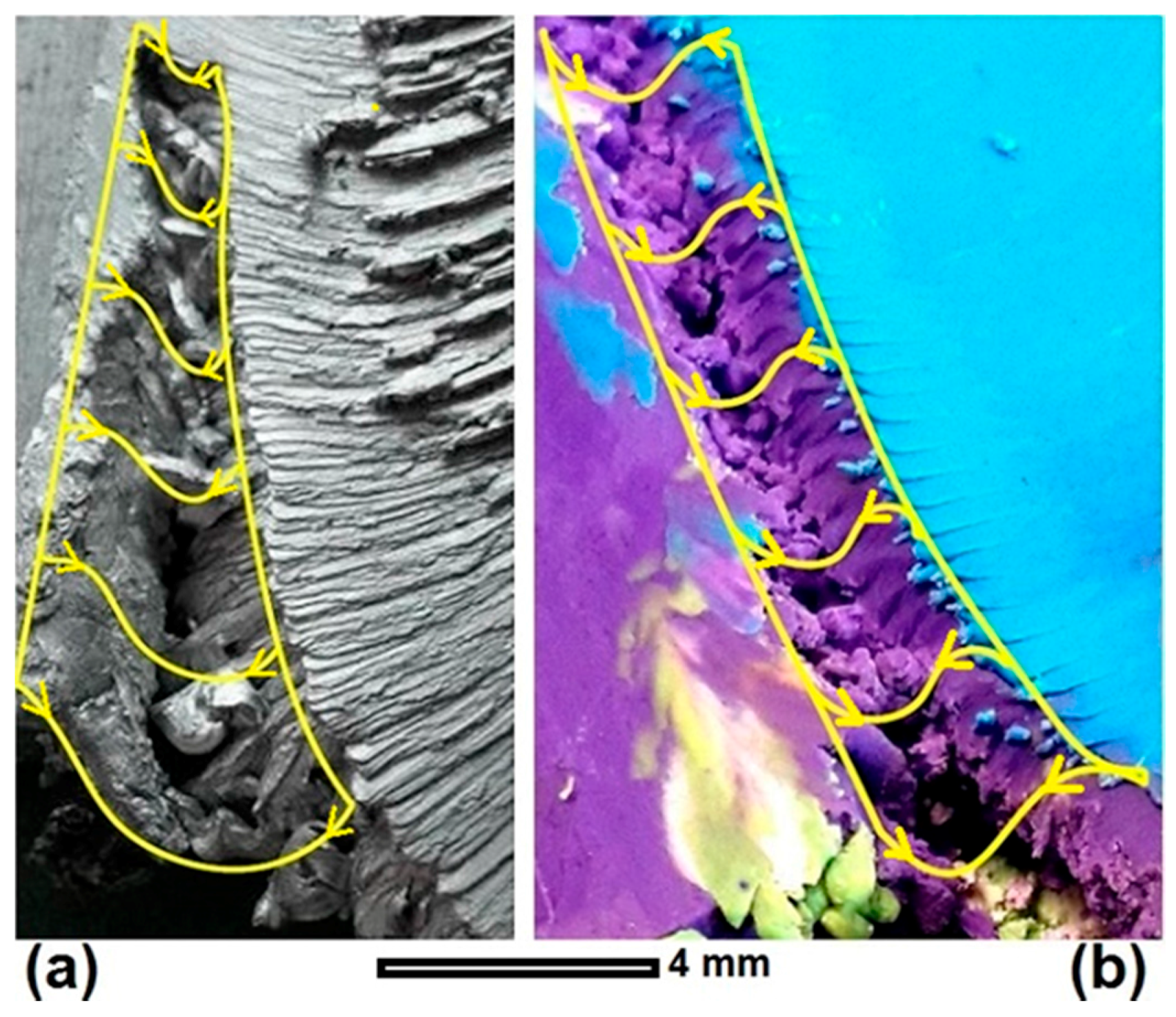
Figure 11.
Speed ratio (ω/V) for different aluminium weld trials.

Figure 12.
The exit zone for an aluminium weld: (a) Top view; (b) Bottom view; (c) End view.

Figure 13.
Analogue model of the exit zone: (a) Top view; (b) Bottom view; (c) End view.

Figure 14.
Schematic of the progression of material disruption in the exit zone (Top view of the tool-workpiece interaction); (a) tool approaches to the extremity edge of the workpiece; shortage of the forward material, (b) the leading edge of the pin arrives to the free surface; disruption happens, (c) pin leaves the plate; a hole is left behind, and (d) the pin and shoulder exit from the workpiece; a keyhole-shaped hole appears as the exit defect.


Table 1.
The parameters of the welding process for the plasticine and aluminium samples.
| Workpiece | Tool Material | Work Temp | DShoulder (mm) | DPin (mm) | DShoulder/DPin | Plate Thickness (mm) | Compression Ratio | Feed ω (rpm) | Speed V (mm/min) | Thread Pitch (mm) | Number of Threads |
|---|---|---|---|---|---|---|---|---|---|---|---|
| AA6082-T6 | H13 Tool Steel | 18 °C | 25 | 5 | 5 | 6 | 3.75% | 400 | 350 | 1.2 | 5 |
| 450 | 350 | ||||||||||
| 500 | 350 | ||||||||||
| 600 | 400 | ||||||||||
| 650 | 400 | ||||||||||
| Multilayered Plasticine | VeroClear plastic | −4 °C | 30 | 6 | 5 | 10 | 3.75% | 75 | 50 | 1.43 | 7 |
© 2018 by the authors. Licensee MDPI, Basel, Switzerland. This article is an open access article distributed under the terms and conditions of the Creative Commons Attribution (CC BY) license (http://creativecommons.org/licenses/by/4.0/).
Share and Cite
MDPI and ACS Style
Tamadon, A.; Pons, D.J.; Sued, K.; Clucas, D. Formation Mechanisms for Entry and Exit Defects in Bobbin Friction Stir Welding. Metals 2018, 8, 33. https://doi.org/10.3390/met8010033
AMA Style
Tamadon A, Pons DJ, Sued K, Clucas D. Formation Mechanisms for Entry and Exit Defects in Bobbin Friction Stir Welding. Metals. 2018; 8(1):33. https://doi.org/10.3390/met8010033
Chicago/Turabian StyleTamadon, Abbas, Dirk J. Pons, Kamil Sued, and Don Clucas. 2018. "Formation Mechanisms for Entry and Exit Defects in Bobbin Friction Stir Welding" Metals 8, no. 1: 33. https://doi.org/10.3390/met8010033
Note that from the first issue of 2016, this journal uses article numbers instead of page numbers. See further details here.