3.1. The Design and Formation Mechanism of Ti5Si3/Ti Composite Ribbon Inoculants Synthesized by In Situ Reaction
Due to the lowest solidification temperature of the eutectic composition alloy, the alloy in its liquid state has higher superheat to a certain degree, delaying solidification. Because the solidification time can be extended, the fluidity usually facilitates a subsequent inoculate refinement. In view of the above reasons, we designed the nominal composition of the master alloy with Ti–8.3Si (wt %) as eutectic composition in this paper.
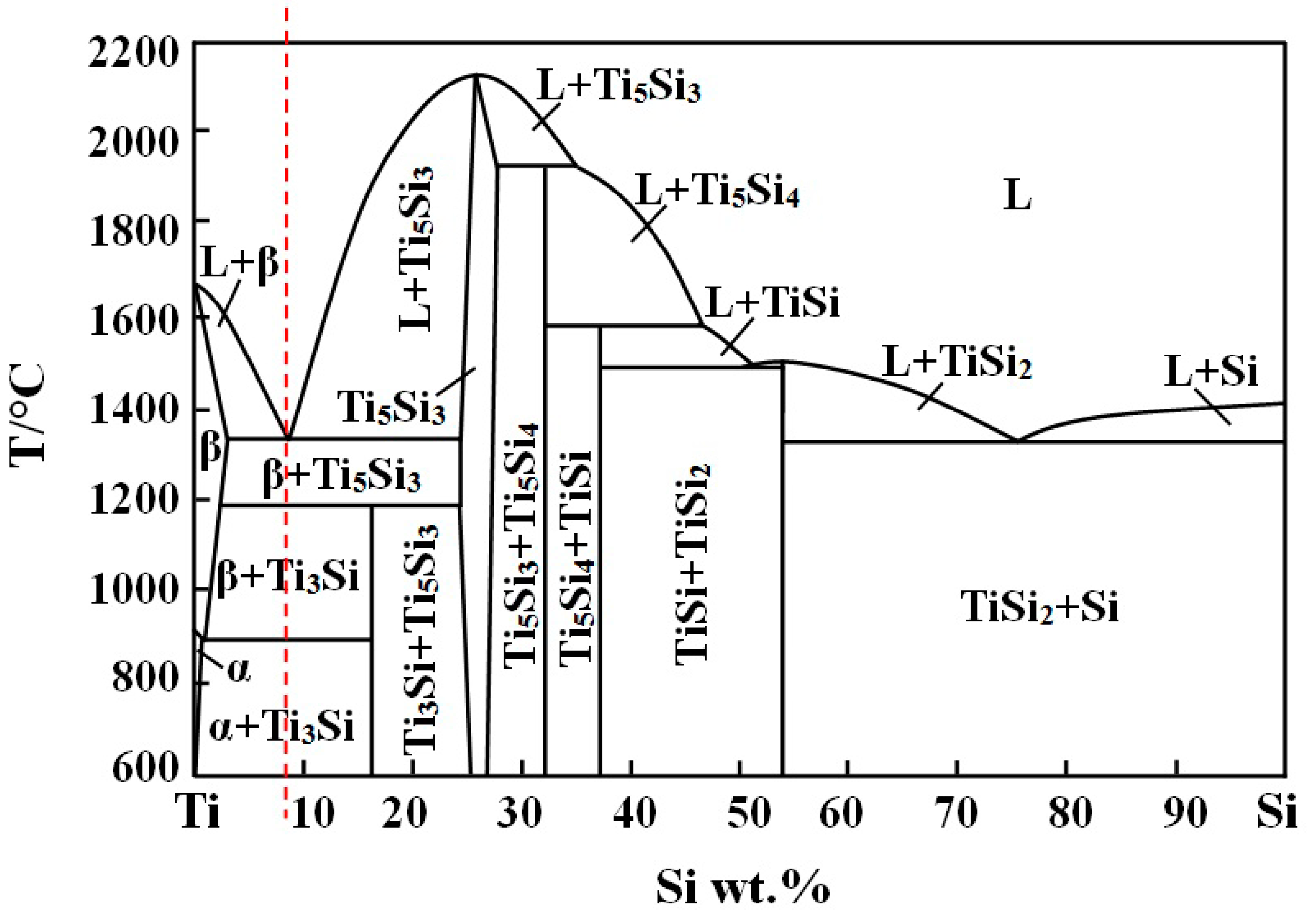
According to the Ti–Si binary phase diagram shown in
Figure 2, when solidification takes place at the eutectic composition of Ti–8.3Si (wt %), the following reactions occur: (1) a eutectic reaction in 1330 °C: L (Ti, Si) → Ti + Ti
5Si
3; (2) a peritectoid reaction in 1170 °C: β-Ti + Ti
5Si
3 → Ti
3Si; and (3) a eutectoid reaction in 865 °C: β-Ti → α-Ti + Ti
3Si. In the above reaction equations, the Ti
3Si is a transitional phase that can be obtained under the condition of heat preservation of 120 h at 1200 °C or heat preservation of 115 h at 1000 °C, in which it has gone through the peritectiod reaction and eutectoid reaction [
22]. In this paper, Ti
5Si
3 is the final reaction product rather than Ti
3Si, while the peritectiod transformation cannot occur due to the cooling condition of the casting process being too fast.
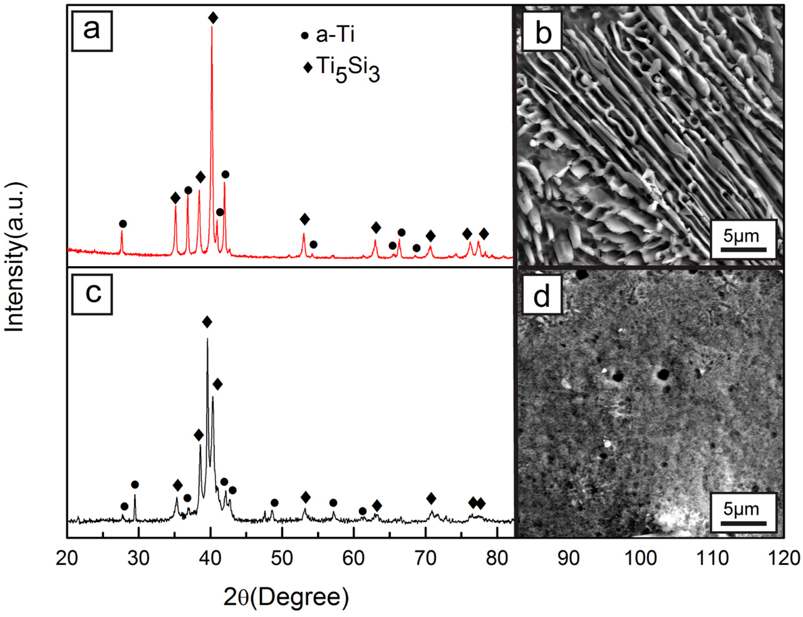
The X-ray diffraction (XRD) pattern of mater alloys and inoculant ribbons are shown in
Figure 3. The α-Ti and Ti
5Si
3 diffraction peaks can be observed in the XRD pattern of the Ti–Si mater alloys (shown in
Figure 3a) without other impurity peaks existing.
Figure 3b shows the SEM images of the Ti–Si master alloys. The SEM morphology presents a typical eutectic microstructure with a large number of bright white precipitate Ti
5Si
3 phases distributed homogeneously in the dark grey α-Ti matrix, and the result agrees well with that in the XRD result in
Figure 3a.
Figure 3d shows the SEM morphology of the inoculants ribbons. It can be seen that the microstructures of the ribbons are refined obviously after the melt-spinning treatment in contrast to the master alloys, which may be attributed to the too rapid cooling rate of the melt-spinning. The XRD pattern of the ribbon inoculants (shown in
Figure 3c) only contains α-Ti and Ti
5Si
3 without other impurity peaks existing. This suggests that melt-spinning is an effective method to refine an inoculant’s microstructure without affecting its phase composition.
Figure 4a shows the microstructures of the in situ Ti
5Si
3/Ti composite inoculant ribbon. It indicates that inerratic isometric-shaped cellular structures are distributed homogeneously in the inoculants ribbon after melt-spinning. The mean particle size of the cell is about 70–90 nm in a uniform structure. The boundary of the cellular structures (region B) is the Si-rich region, while the core of the cellular structures (region A) represents a region of low Si content. Because the melt-spinning is a process with short heating time and rapid heating rate, dissolving Si from the Ti
5Si
3 phase has no time to diffuse in the rapid cooling process to form a supersaturated solid solution in a certain region of the Ti-matrix. The schematic diagram of the formation process of the cellular interface is shown in
Figure 4d.
Due to solidification in the Ti–Si alloy occurring in a temperature range from liquid temperature to room temperature, the equilibrium compositions of the liquid phase and the solid phase in the two phase regions are different. Therefore, the Equilibrium partition coefficient can be indicated as:
where
CS Ti–Si is the equilibrium composition of the solid phase, and
CL Ti–Si is the equilibrium composition of the liquid phase. In the solidification process of the Ti–Si alloy, the solute atoms are redistributed and enriched in the liquid, especially in the front of the interface. So, the solidification point is lower with the result of the heat’s dissipation, and there exists a temperature gradient in the liquid phase resulting in a constitutional supercooling. When the Ti–Si alloy solidifies, the solute atoms are released on the front of the solid/liquid interface (
k0 < 1). So, besides the influence of the heat flux, the solid growth is also affected by the diffusion of the solute atoms playing a main role in the interface morphology. Due to the rough interface of the metal, the crystal morphology of the pure metal is affected by the temperature gradient. However, for solid solution alloys, beside the influence of the temperature gradient, the crystal morphology is affected by constitutional supercooling more seriously. Under the negative temperature gradient, the crystal morphology of the solid solution tends to grow into dendritic-shape that is the same as pure metal, while under the positive temperature gradient, the constitutional supercooling formed by enrichment of the solute elements at the forefront of the solid-liquid interface will produce a great impact on the crystal morphology of the solid solution alloys. Under a certain temperature gradient, there are smaller constitutional supercooling regions existing in the front of the solid-liquid interface, so the several tiny protrusions on the smooth interface can grow into the supercooling regions. The protrusions grow not only along the perpendicular direction to the solid-liquid interface, but also in the other direction to vent the solute into the surrounding environment. Because the diffraction condition of the solute atoms at the top of the protrusions is better than that in the other direction, it is beneficial to diffusion from the solid-liquid interface to the liquid. As a result, the solute concentrations of the grooves between the adjacent protrusions increase more seriously than those on the top, which leads to solute enrichment in the grooves. At the same time, the equilibrium crystallization temperature of the liquid decreased with the increase of solute concentration. Therefore, the equilibrium crystallization temperature of the enriched grooves with solute atoms becomes lower and the supercooling degree becomes smaller, which makes the growth speed of the protrusions in the grooves slower than that on the top parts and the grooves more deepened. As the constituent supercooling on the front of the interface increases, the protrusions on the interface increase too, connecting and forming regular networks. Under a certain condition, the interface reaches a steady state eventually, then crystal growth process is accompanied by the movement of an uneven stable interface to the liquid at a constant speed, forming a cellular structure eventually.
After the melt-spinning treatment, the inoculant ribbons show a microstructure evolution, which has more uniform cores to provide heterogeneous nucleation. So, the in situ Ti5Si3/Ti composite inoculant is expected to be a new type of effective inoculant to refine titanium alloys and TMCs with a favorable melt-spinning processing step.
3.2. Refinement Effect of Titanium Matrix Composites (TMCs)
To examine the refining effect of the in situ Ti
5Si
3/Ti composite ribbon inoculants, pure titanium was used as a reference to check the different added fractions of inoculants.
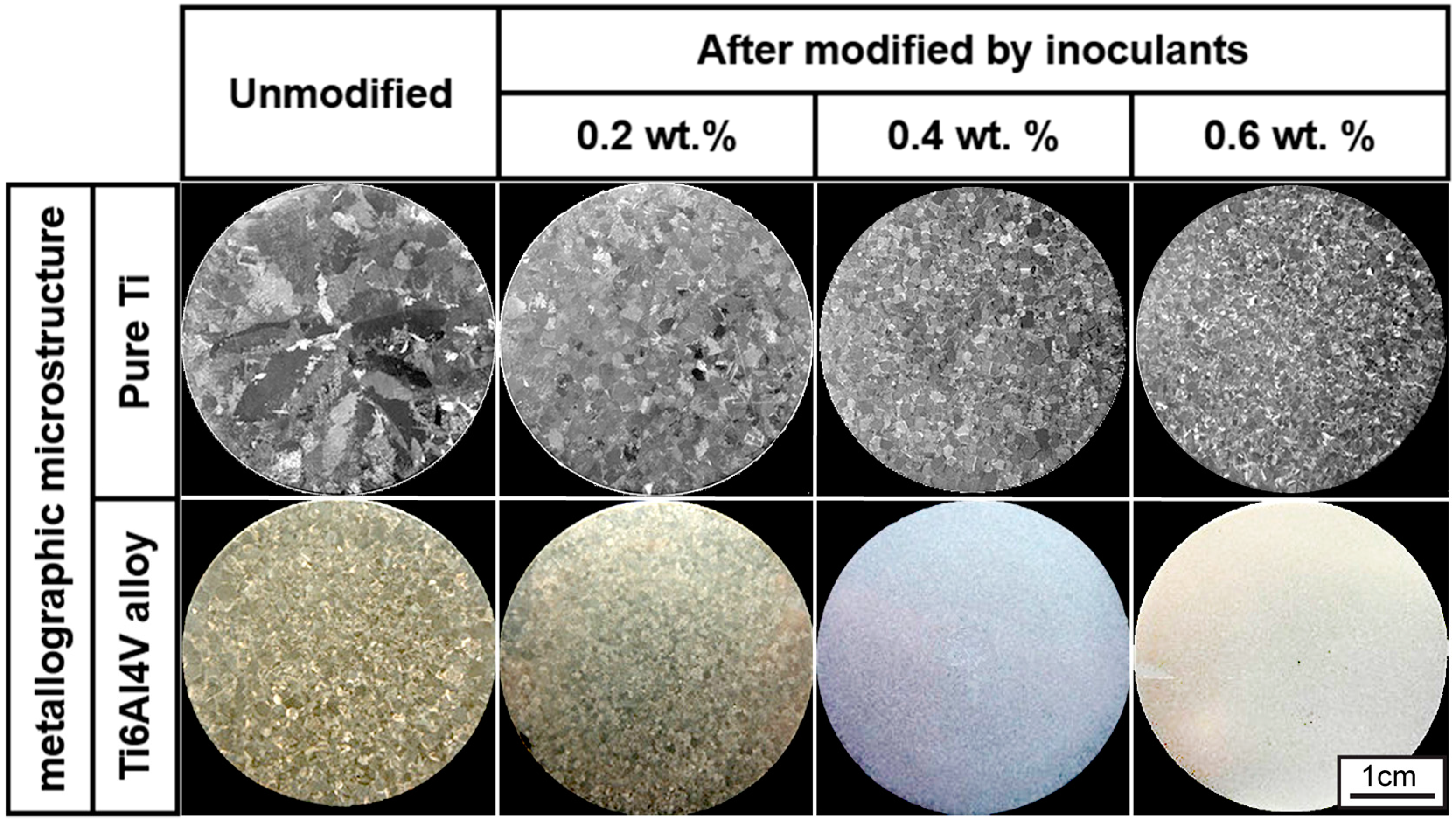
Figure 5 shows the metallographic microstructure of Ti and Ti6Al4V alloys unmodified and modified by in situ Ti
5Si
3/Ti composite ribbon inoculants with different weight percentages. Generally, the inoculants present a refining effect. There is a trend that the refining effect becomes more effective as the adding fraction of the inoculants is increased.
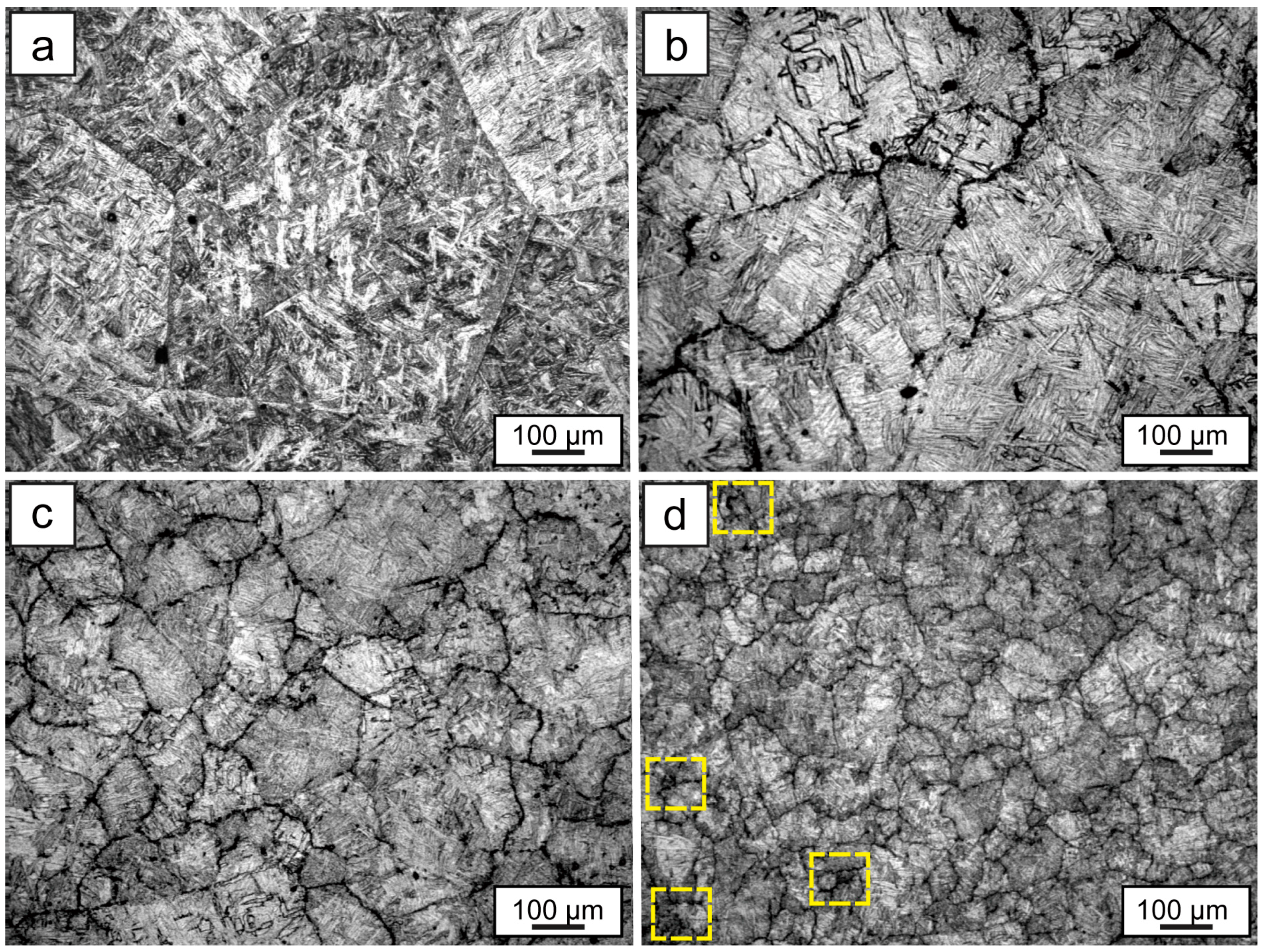
Figure 6 shows the optical microstructure of the TMCs. It is indicated in
Figure 6 that the grain size of the TMC sample is significantly decreased with the addition of the inoculants. It shows that the grain size of TMCs without inoculation is about 650 μm. Interestingly, by adding 0.6 wt % Ti
5Si
3/Ti composite ribbon inoculants, this grain size is refined and transformed into small grains with a size of about 110 μm. Such a small adding fraction with such a significant refining effect suggests that the in situ Ti
5Si
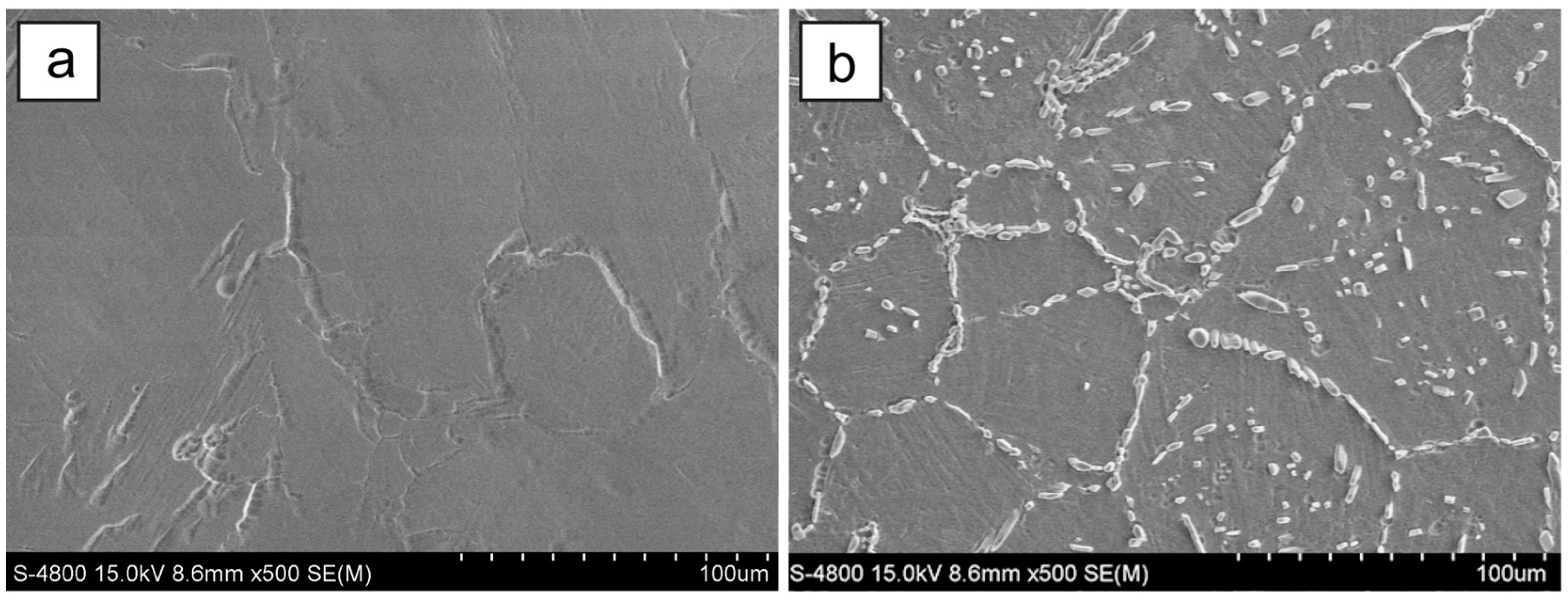
3/Ti composite ribbons are one type of efficient inoculant to modify a Ti6Al4V alloy melt. In addition, the microstructure of Ti6Al4V unmodified is a mixture of a plate-like acicular alpha and beta phase with large beta grains (shown in
Figure 6a). By adding 0.2 wt % Ti
5Si
3/Ti composite ribbon inoculants, the acicular-like structure from the supersaturated alpha phase is turned into finer grains with the decreasing of grain size. With the increasing of the inoculant content, the size of the acicular structure becomes even smaller. But when adding 0.6 wt % inoculant, a small amount of impurity is present at the boundary of the tiny grains, and little tiny holes and defects also emerge in the matrix (shown in the rectangular regions of
Figure 6d).
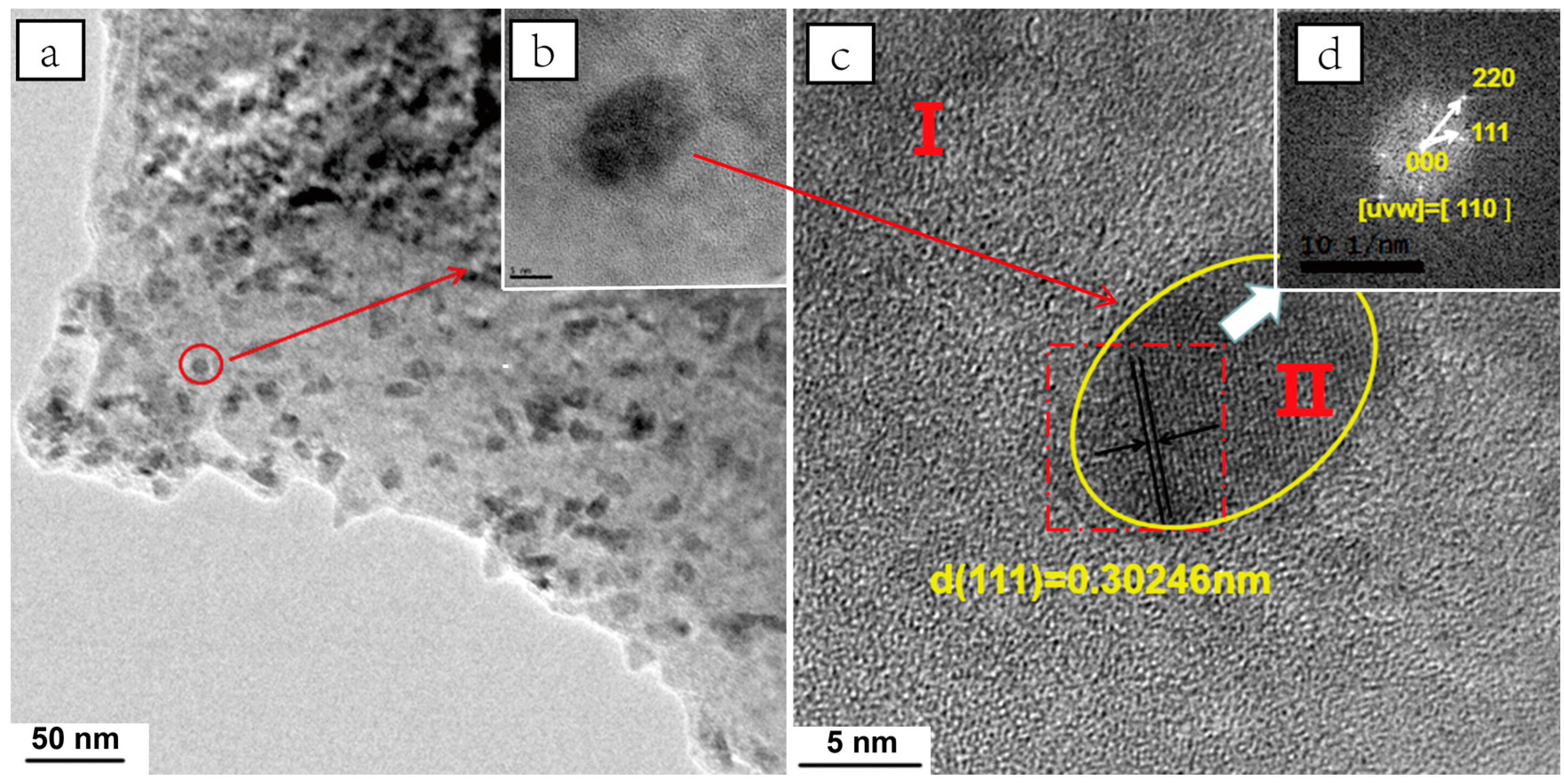
Figure 7 shows transmission electron microscope (TEM) images of the TMCs in a refined and reinforced condition by in situ Ti
5Si
3/Ti composite ribbon inoculants. The Ti
5Si
3 particle, which can be observed by transmission electron microscope, is too small to be seen by scanning electron microscope. One can see clearly that the Ti
5Si
3 particles with a size of less than 10 nm are embedded in the matrix homogeneously. It is necessary for us to point out that the nano-scale Ti
5Si
3 particles exist inside the Ti6Al4V alloy grain, which means that the nano-Ti
5Si
3 particles can exist in a stable state in the melt and act as cores for heterogeneous nucleation. At the same time, the nano-scale Ti
5Si
3 particles greatly contribute to the refining and reinforcement of Ti6Al4V alloy. To further confirm the morphology and size of the Ti
5Si
3 particles, the HRTEM image is shown in
Figure 7c. The Fast Fourier transform (FFT) analysis in
Figure 7d corresponds to the [110] zone axis of the hexagonal Ti
5Si
3 structure, so it is confirmed that this is the major phase in the beam spot area.
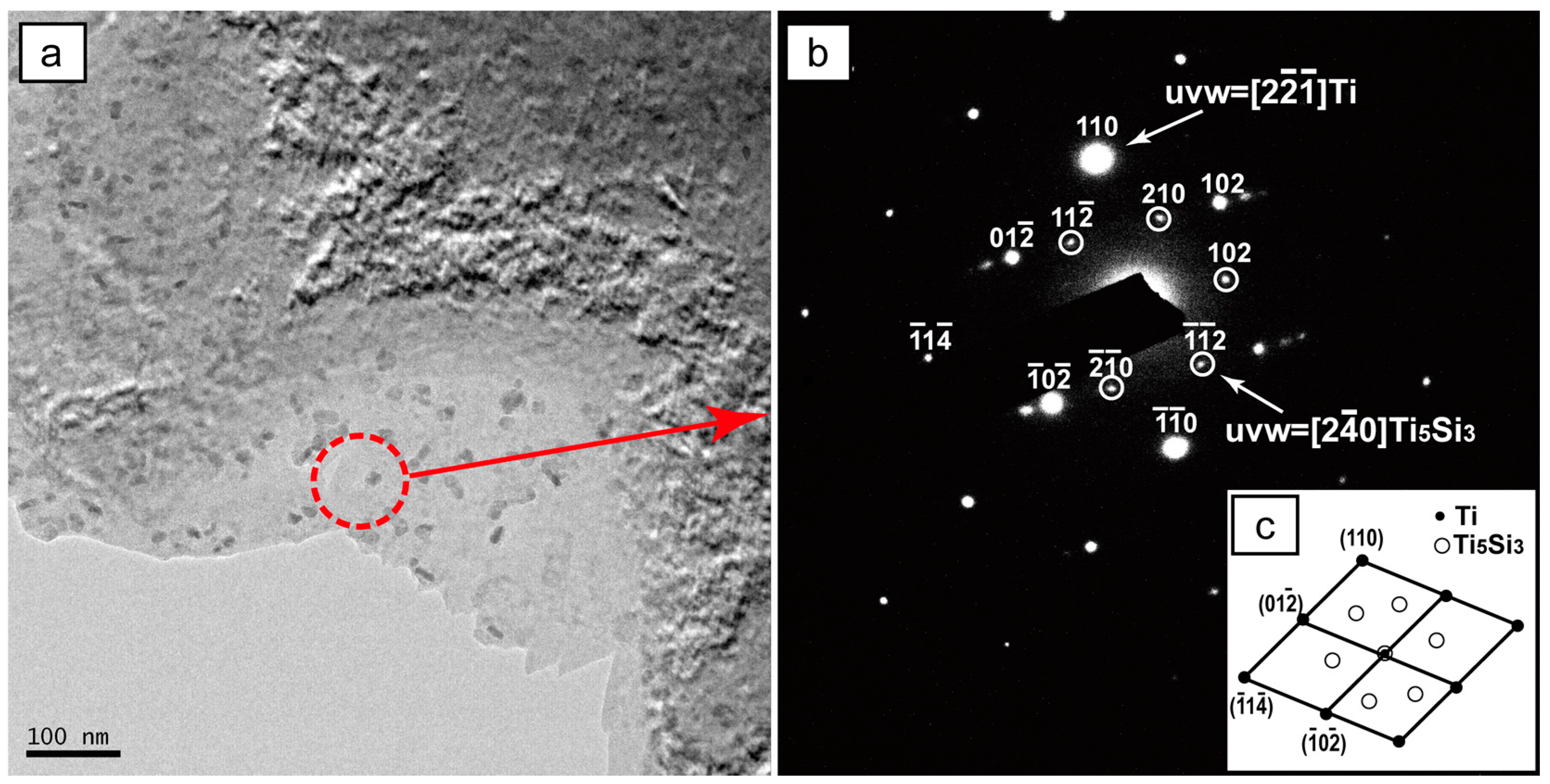
The electron diffraction imaging is shown in
Figure 8. Two groups of diffraction spots corresponding to Ti and Ti
5Si
3 can be observed in
Figure 8b. The main phase corresponds to titanium, and the second phase is identified as a Ti
5Si
3 phase with a hexagonal crystal structure (a = 0.239 nm). There is no evidence of a clear orientation relationship between the Ti
5Si
3 phase and the surrounding Ti matrix. Therefore, it can be suggested that the particles shown in
Figure 8a are Ti
5Si
3 phase that came from the addition of the in situ Ti
5Si
3/Ti composite ribbon inoculants.
The refining mechanism of inoculants can be explained from the following aspects. First of all, the good interface bonding is one of the factors that promote a refinement effect [
23,
24]. The homogeneously distributed nano-Ti
5Si
3 particles were directly formed in the Ti
5Si
3/Ti composite inoculants by the in situ reaction, thus the matrix/reinforcement interface is not only clean and taintless, but also these in situ particles have a good wettability and strong interface bonding with the matrix of TMCs that is attributed to the in situ Ti
5Si
3/Ti inoculants, which is itself a type of Ti
5Si
3 precipitate phase reinforced Ti matrix composite with a fine grain. When introducing an enhanced phase into the titanium alloys via the composite inoculants, the Ti matrix of the inoculants can be melted in the titanium alloy and the tiny reinforcing particles are distributed in the melt homogeneously, which ensures a good wettability between the reinforcing particles and matrix, thus leading to a desirable interface bonding. At the same time, the first-melted Ti matrix in the inoculant leads to the quantity of the crystal nuclei increasing, which can increase the number of short-range ordered clusters in a Ti6Al4V alloy melt. Furthermore, a small amount of silicon diffused into intervals of the short-range order in the Ti6Al4V melt. The combination of these two aspects increased the homogeneous nucleation of the Ti6Al4V alloy melt.
On the other hand, the tiny nano-Ti
5Si
3 reinforcing particles are homogeneously distributed in the TMCs matrix as shown in
Figure 7a, indicating that their size is less than 10 nm. The generation of nano-sized reinforcing particles is mainly due to the previous melt-spun, which brings a great degree of supercooling through the huge cooling rate. With a constant silicon element content, the number and size of the reinforcing particles showed an inverse proportion. While the size of the reinforcing particles become smaller, the number of the nano-sized particles increased considerably, providing more cores for heterogeneous nucleation, and improving the nucleation rate and promoting heterogeneous nucleation. In addition, according to Stoke’s Formula [
25,
26]:
where
ut is the sedimentation rate of the particles,
dp is the particle radius,
g is acceleration of gravity,
is the particle density and
is the melt viscosity, it can be seen that the particle sedimentation rate is directly proportional to the particle radius. When the Ti
5Si
3 particle radius is decreased, the sedimentation rate is reduced, which is beneficial to the homogeneous distribution of the nano-Ti
5Si
3 reinforcing particles in the melt, and avoids the gravity segregation caused by the differences of density between the particles and the melt. Meanwhile, the time of the grain refining could be extended and the grain refining effect could be improved.
Finally, it is important to indicate that the heterogeneous nucleation of the titanium grain on the Ti
5Si
3 phases in the TMCs is playing a vital role in the grain refining. Owing to the nano-scale effect, the Ti
5Si
3 particles have high surface energy and a strong adsorption effect. So, the titanium grain can attach to the existing nano-Ti
5Si
3 crystal nucleus and nucleate in a smaller degree of supercooling due to the reduced nucleation interface energy. However, the good lattice mismatch between the reinforcing phase and the matrix phase plays a key role in the reduction of the interfacial energy. As we know, the typical structure of Ti6Al4V alloys is composed of a primary β-Ti phase and a laminar α-Ti phase. The α-Ti phase is precipitated during the β-α transformation. The α-Ti phase and β-Ti phase follow the specific orientation relationship: {0001}α//{110}β, <1120>α//<110>β. The different crystal lattice parameters are listed in
Table 1. Obviously, the Ti
5Si
3 phase as well as the α-Ti phase belong to the hexagonal crystal system, owing the close-packed plane (0001) and a spacing of d0001 = 0.516 nm. Generally, the mismatch degree of the close-packed plane can be expressed by the Turnbull–Vonnegut Formula [
17]:
where
as is the close-packed spacing of the parent phase, and
an is the close-packed spacing of the precipitate phase. The smaller the degree of mismatch
δ, the better the matrix and nucleation of crystal lattice matches and the smaller the change of energy causing the lattice mismatch, while the smaller interfacial energy makes the heterogeneous nucleation more likely to happen. According to the planar lattice mismatch theory by Bramfitt [
27], the occurrence of nucleation particles that are the most effective with the mismatch of the two phases is less than 6%, so the Ti
5Si
3 phase can be used as the effective nucleating agent for the titanium alloy. Due to the same crystal system and the small mismatch between Ti
5Si
3 and α-Ti, the α-Ti tends to grow along the (0001) plane of Ti
5Si
3. As the content of Ti
5Si
3 reinforcement is increased, there would be more heterogeneous nuclei, leading to the refinement of α-Ti. When refined by Ti
5Si
3 particles, there would be more grain boundaries of α-Ti than in the β-Ti phase to heterogeneously nucleate. So, the nucleation rate of the β-Ti phase will be increased. Furthermore, the smaller sized α-Ti grain would restrain the growth space for the β-Ti phase, which could also cause a refining of β-Ti.
3.3. Mechanical Properties of TMCs
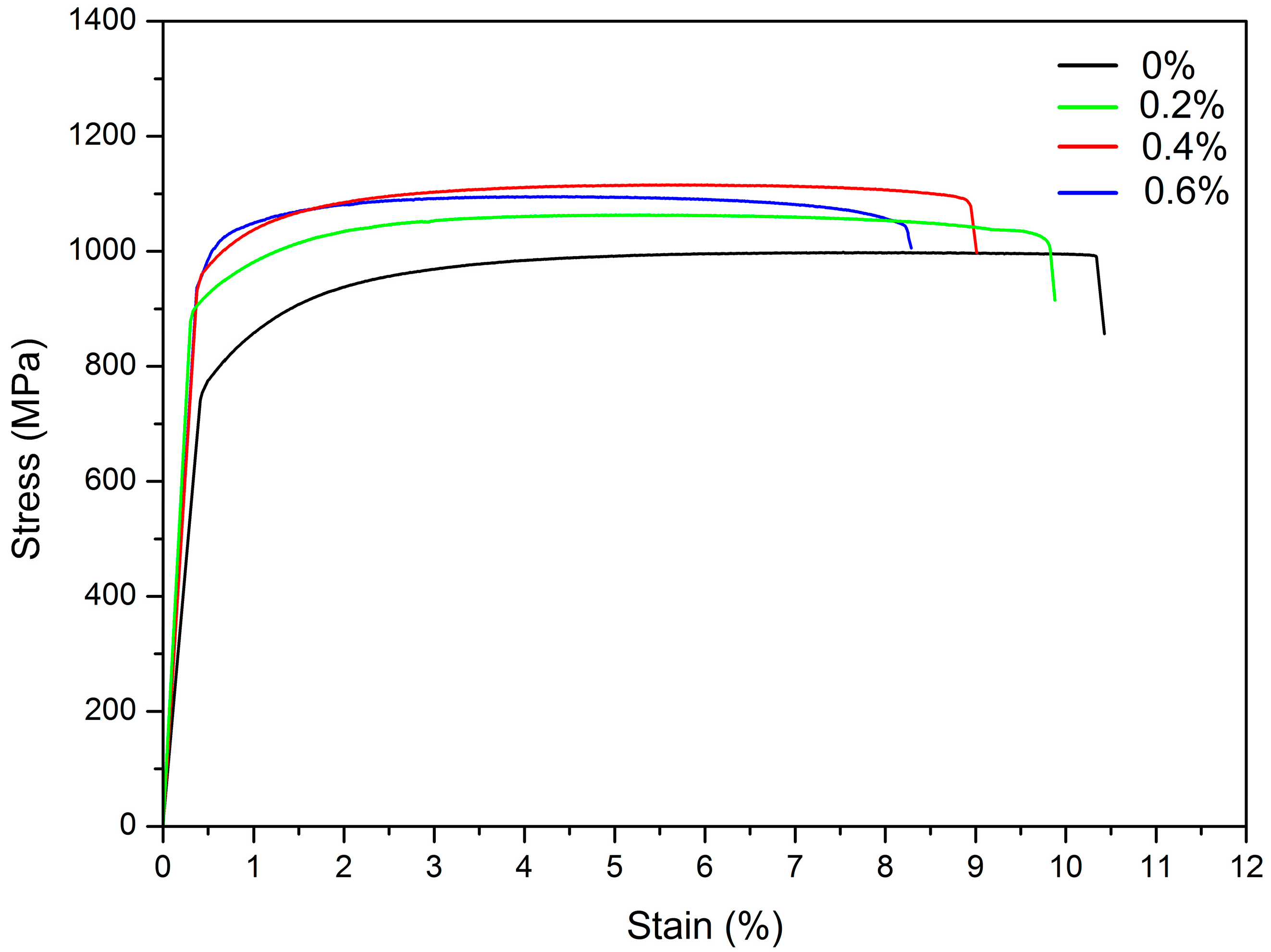
The mechanical properties of TMCs identified from the tensile tests are illustrated in
Figure 9. Generally, the tensile strength of the TMCs was improved with the increase of inoculant content. However, in contrast, the elongation decreased with the increase of inoculant content. When the addition of in situ Ti
5Si
3/Ti composite inoculants reaches 0.4 wt %, the TMCs show the best mechanical properties of tensile strength, reaching 1105 MPa, which represents an increase of 12.6% compared to Ti6Al4V, where the elongation decreased by 13.1%. When increasing the inoculant content to 0.6 wt by adding 0.6 wt % Ti
5Si
3/Ti composite ribbon inoculants, the grain size is refined smaller. However, with an overdose of inoculants of 0.6 wt %, a small amount of impurity is present at the boundaries of the tiny grains, and little tiny holes also emerge in the matrix (shown in
Figure 6d). The intermetallic compound coming from the inoculants attached at the grain boundary dissected the continuity of the substrate. So, the tensile strength decreased when adding 0.6 wt % inoculant.
The TMCs show the characteristics of brittle fracture, as shown in
Figure 10, and with the increasing of the inoculant content the trend of the brittle fracture becomes more serious. There are some tearing ridges and a few dimples present in the matrix of the TMCs unmodified (shown in
Figure 10a). After modification by adding 0.2 wt % inoculant, the dimples have disappeared and the river pattern appears in the fracture morphology, which shows the typical characteristics of a brittle fracture. With the increasing of inoculant content, the trend of the brittle fracture becomes more serious. When modified by 0.6 wt % inoculant, large cleavage steps appear in the fracture surface. Furthermore, we can see the tearing ridges become short and thick with the increasing of inoculant content. Because the formation of the tearing ridge is due to the intercrystalline fracture, the size of the grain is decreased with the inoculant content increased, which causes the tearing ridges to turn short and thick. These changing trends of the fracture morphology coincide with the results of the stress-strain curves from the tensile tests. The above two aspects suggest that the strength of the TMCs increased and their toughness decreased by modification with inoculants. Considering the increase of tensile strength, we suggest that TMCs with an added 0.4 wt % inoculant have the optimal mechanical properties.
The improvement in mechanical properties of the TMCs can be explained from the interaction between the grain refining and the particle reinforcing effects. The reinforcing mechanism of the TMCs can be analyzed and summarized as follows: a fine-grain strengthening mechanism, a particle strengthening mechanism, and a solution strengthening mechanism. For tensile strength, the first two increase levels of strength. The grain refinement is the result of the grain boundary being pinned to impede dislocation movement, while the particle reinforcement acts as a dispersion, strengthening that the nano-scale particles pin the motion of dislocations. Moreover, the strengthening of the TMCs enhanced with the reinforcement content can be explained by the Orowan strengthening mechanism, where critical shear stress results in the dislocation line by passing the reinforcement particles, expressed as:
where
G is the shear modulus of the matrix,
b is Buerger’s vector, and
r is the radius of the curvature of the dislocation line bending. The distance between the reinforcement particles
L = 2
r, so Equation (3) could be written as:
It is clearly seen from Equation (4) that with adding the content of the particles, the inoculant content of reinforcement increases the distance L. The solution strengthening, on the other hand, is composed of a primary β-Ti phase and a laminar α-Ti phase, while the alloying elements caused a lattice distortion and hinder the dislocation motion contributing to the improvement of the strengthening.
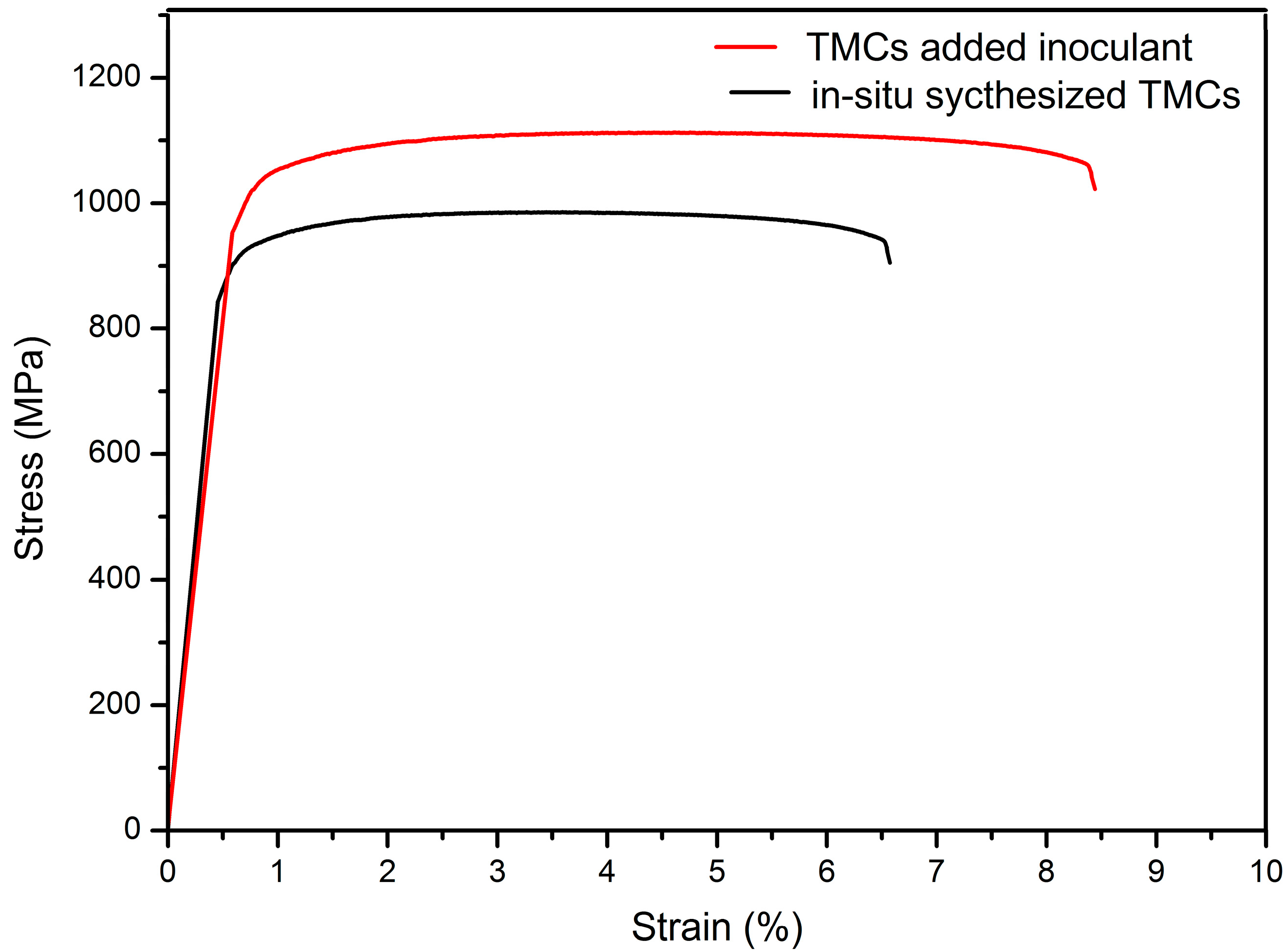
It is important to point out that the mechanical properties of the TMCs prepared by adding inoculant ribbons are more different from the TMCs prepared by adding Si powers to the Ti6Al4V alloy melt directly. As shown in
Figure 11, the mechanical properties of tensile strength and elongation are superior. This result is consistent with previous results reported by Zhao et al. [
17]. This is due to the homogeneous distribution of nano-scale Ti
5Si
3 reinforcement particles as described above (shown in
Figure 8a). However, for the in situ synthesized TMCs, the reinforcement appeared segregated at the grain boundaries (shown in
Figure 12b), which could be a serious reason for the decrease of the mechanical properties. Related studies [
28] show that when the particle (acting as a core for heterogeneous nucleation) is less than 400 nm, the particles will be swallowed up into the interior of the matrix metal grain to result in an improved intracrystalline reinforcing effect. On the contrary, when the size of an in situ reinforcement particle is larger than 400 nm, it would be pushed to the grain boundary that not only does not have a reinforcement effect, but also lacerates the substrate reducing the mechanical properties.
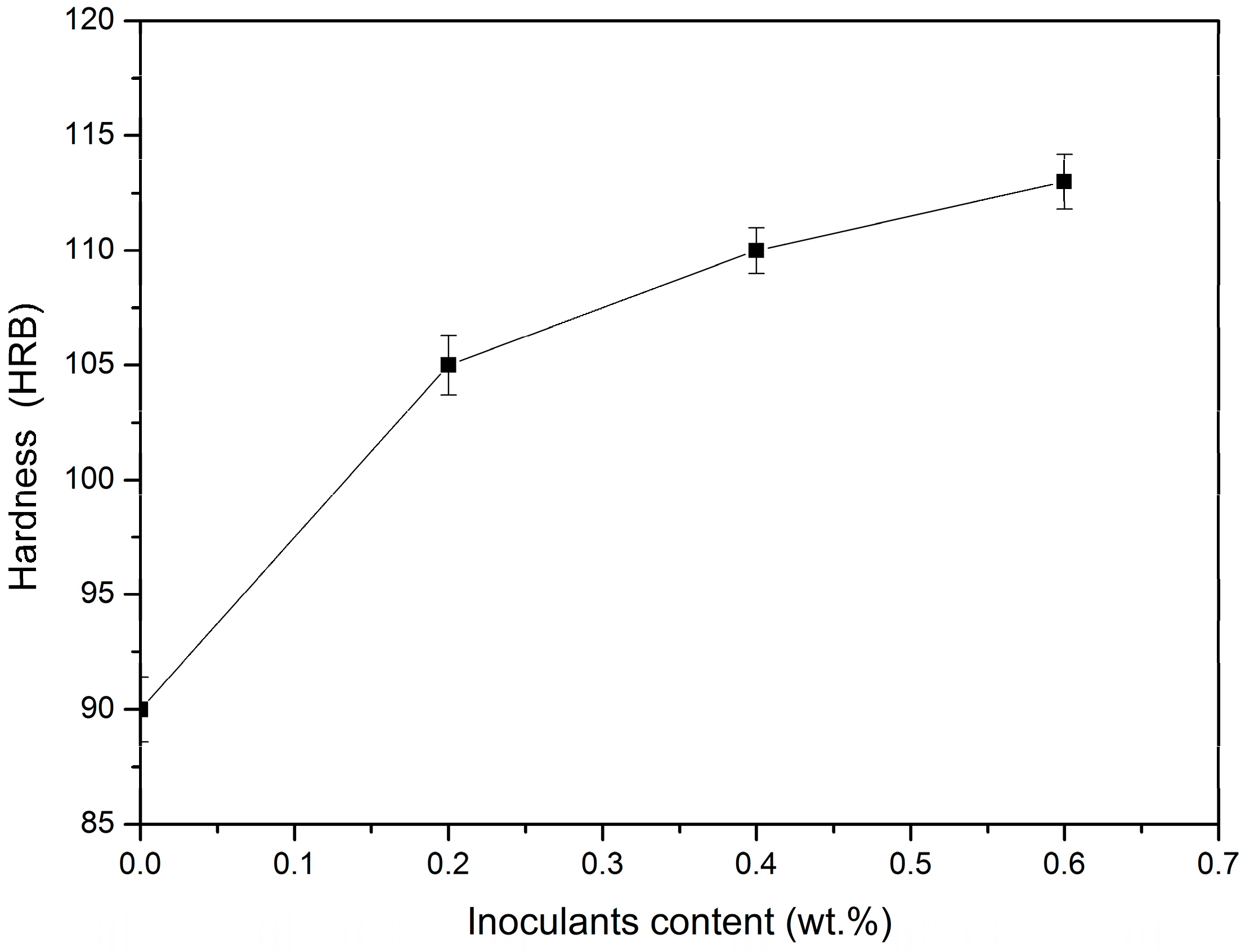
Figure 13 shows the result of the hardness test. For the TMCs, the microhardness values had a tendency to increase as the inoculate content increased. In particular, the mcirohardness of the alloys refined by adding the 0.6 wt % Ti
5Si
3/Ti composite inoculant has reached up to 113.2 HRB, which is improved 25.8% than that without inoculation. So, we can think that the optimization of the microstructure and the improvement of the comprehensive mechanical properties of TCMs are also benefited by the hard reinforcing particles and the refined grain size.
It can be seen from
Figure 14 that the value of the impact toughness has a general trend of decrease with an increased weight fraction of inoculant. However, when the weight fraction of the inoculant is 0.2 wt %, the impact toughness is 28.1 J/cm
2, and in the SEM images of the impact fracture appear dimples and cleavage planes (shown in
Figure 14b), which show the characteristics of cleavage fracture. When the weight fraction of inoculant is increased to 0.6 wt %, the impact toughness is reduced to 16.8 J/cm
2. The SEM images of the impact fracture present a rock candy shape feature (shown in
Figure 14d), which suggests that the fracture mode has been turned into an intergranular fracture. Compared with the static tensile test, the embrittlement of the TMCs in the impact test occurs more seriously.
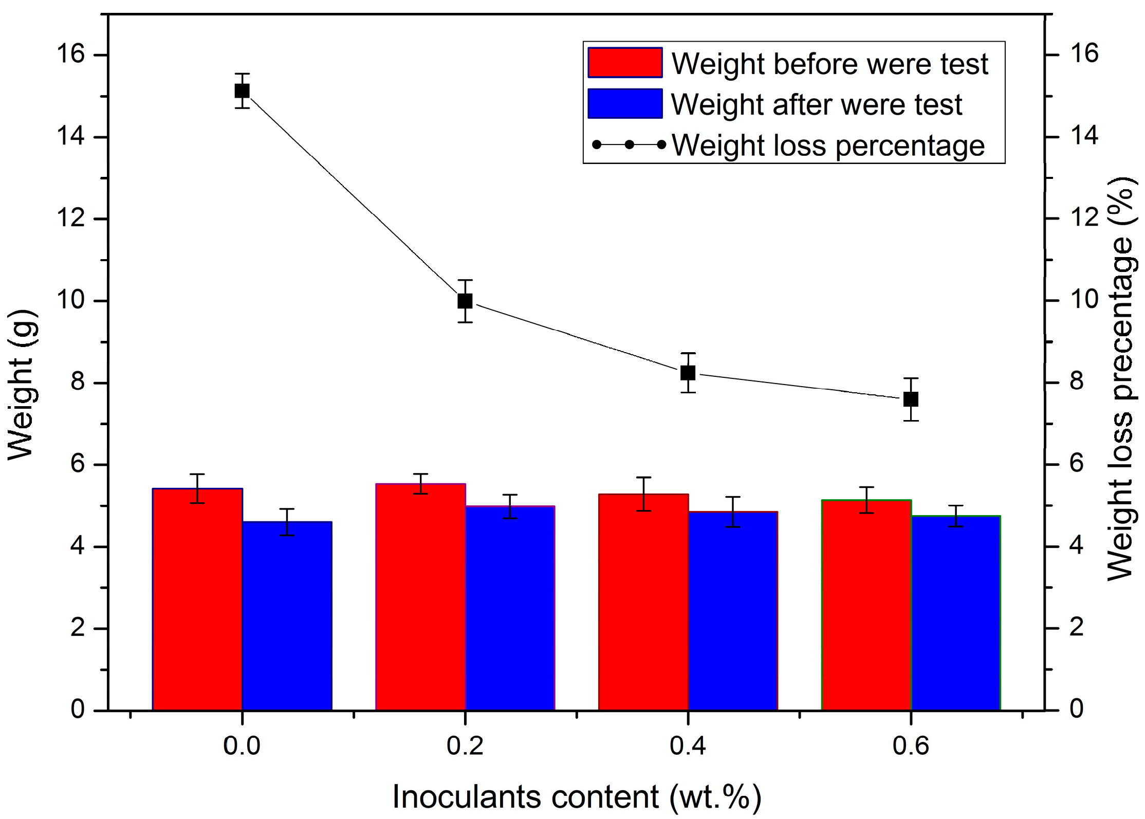
Figure 15 shows the friction and wearing test result of the TMCs. The values of weight loss percentage present a similar trend to that of the impact toughness in that the weight loss percentage is decreased as the reinforcement content is increased, which means that the wear-resisting property of the TMCs improved.
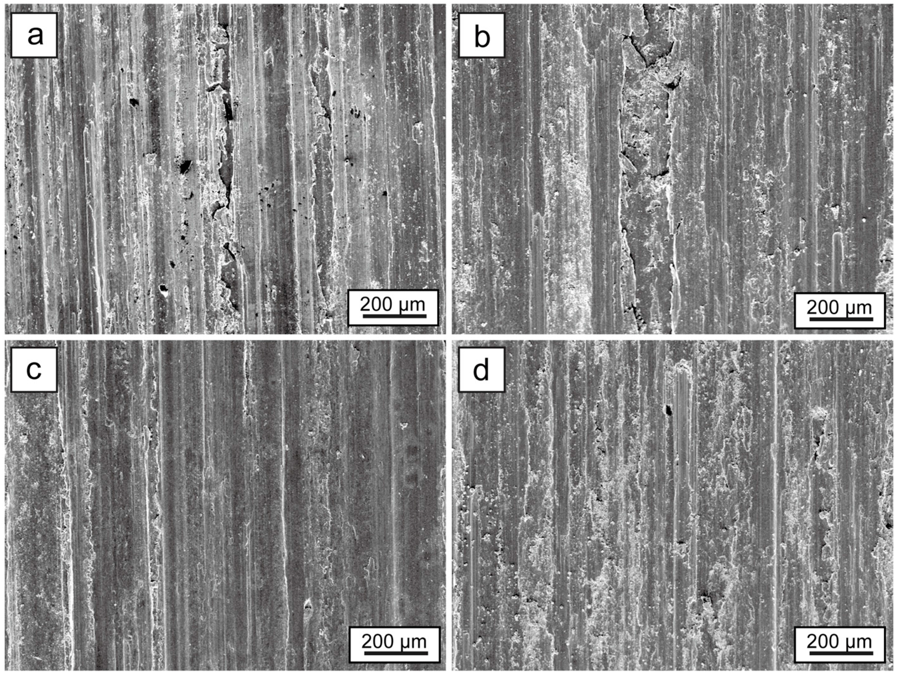
Figure 16 shows the SEM images of the wear surfaces. With the increase of the reinforcement content, a ploughed furrow appears and the spalled wear debris disappears gradually, which suggests that the friction and wear mechanism is abrasive wear instead of adhesive wear. The changing trends of the hardness, impact properties, and the wear resistance properties of the TMCs influenced by the inoculant content is consistent with the tensile properties of the TMCs.


