A Finite Element Model to Simulate Defect Formation during Friction Stir Welding

State Key Laboratory of Robotics, Shenyang Institute of Automation, Chinese Academy of Sciences, Shenyang 110016, China
*
Author to whom correspondence should be addressed.
Metals 2017, 7(7), 256; https://doi.org/10.3390/met7070256
Submission received: 16 June 2017
/
Revised: 27 June 2017
/
Accepted: 28 June 2017
/
Published: 7 July 2017
(This article belongs to the Special Issue Recent Achievements in Rotary, Linear and Friction Stir Welding of Metals Alloys)
Abstract
:In this study, a 3D coupled thermo-mechanical finite element model is developed to predict and analyze the defect formation during friction stir welding based on coupled Eulerian Lagrangian method. The model is validated by comparing the estimated welding temperature, processed zone shape and void size with those obtained experimentally. The results compared indicate that the simulated temperature and the data measured are in good agreement with each other. In addition, the model can predict the plasticized zone shape and the presence of a void in the weld quite accurately. However, the void size is overestimated. The effects of welding parameters and tool pin profile are also analyzed. The results reveal that welding at low welding speed or high tool rotational speed could produce a smaller void. Moreover, compared to a smooth tool pin, a featured tool pin can enhance plastic flow in the weld and achieve defect-free weldment. The results are helpful for the optimization of the welding process and the design of welding tools.
1. Introduction
Friction stir welding (FSW) is a novel solid-state joining technique invented by the welding institute (TWI) in 1991 [1]. It has become a unique technique well suited to joining many hard-to-weld metals, especially high strength aluminum alloys and some dissimilar metals. Due to the advantages over traditional fusion joining techniques, such as the lack of melting, low defect and low distortion, FSW has been widely applied in the aerospace, shipbuilding, automobile and railway industries [2,3,4].
FSW is a multi-physics problem which involves excessive material deformation at high strain rate and elevated temperature. The material flow around the welding tool is very complex depending on the tool geometry, material property and other process parameters, namely rate of rotation and traverse, tool tilt, contact load, etc. [5]. It is important to understand the material flow characteristics for optimal tool design and process parameter combinations, because it determines the effectiveness and mechanical properties of the joints.
Since the invention of FSW, several researchers have performed experiments in an attempt to understand the material flow around the welding tool, and a number of approaches, such as tracer technique by marker [6,7,8], FSW of dissimilar alloys/metals [9,10] and microstructural observations [11,12], have been successfully used to visualize the material flow pattern in FSW. However, the information obtained from a single test is very limited. In order to fully understand the material flow behavior in FSW, a lot of welding tests need to be done, which is time-consuming and exhausting.
Compared with the experimental method, numerical simulation is a more convenient and effective method to study FSW. This is because visualization of the material flow, temperature field, stresses, and strains involved during the whole FSW process can be easily obtained with less effort and less cost by numerical method. Moreover, numerical simulation techniques can avoid many repeating experiments and save lots of energy. For these reasons, different modeling techniques, such as computational fluid dynamics (CFD) and arbitrary Lagrangian Eulerian formulation (ALE), have been proposed to simulate FSW process.
Seidel T.U. and Reynolds A.P. [13] developed a 2D thermal model based on laminar, viscous and non-Newtonian flow around a circular cylinder. They observed that significant vertical mixing occurred during FSW, particularly at low values of welding speed to rotational speed ratios. This fact indicated the need for three-dimensional models. Ulysse P. [14] developed a 3D viscoplastic model to simulate FSW using a commercial CFD software. He studied the effects of welding and tool rotational speeds on temperature, loads on the tool pin, and flow of particles near the rotating pin. He found that the forces on the pin increase with increasing welding speed, and decrease with increasing rotational speed. Moreover, the temperatures predicted were overestimated compared to experimentally measured ones. Colegrove P.A. and Shercliff H.R. [15,16] used a commercial CFD code, FLUENT, to develop a 3D model to understand the temperature distribution and material flow around a complex threaded tool during friction stir welding of Al7075 aluminum alloy. In the model, no slip condition was assumed at the tool/workpiece interface and the heat dissipation to backing plate was considered. Although the model could capture many of the real process characteristics, it over-predicted the temperature and size of the deformation zone, and the effect of the rotational speed on peak temperature could not be adequately represented by the model. Long T. and Reynolds A.P. [17] used a CFD-based model to study the effect of material properties and process parameters on the x-axis force, material flow and potential defect formation. With the pattern of material flow around the tool known for different process parameters, the formation of defects could be explained. Carlone P. and Palazzo G.S. [18] developed a CFD Eulerian model to simulate the FSW process of AA2024-T3 using the ANSYS CFX commercial package and validated the model by comparison with thermographic observation of the process. The influence of rotating and welding speed on microstructure, mechanical properties and joint quality were discussed. The eventual defects in the welded specimens were evaluated through microscopic analysis, in addition, grain size, microstructure in the welding zone and microhardness profiles were evaluated as well by metallographic observation. By taking into account numerically computed temperature and strain rate distributions, experimental data were analyzed in detail, which could provide useful information for setting parameters.
With the advance in computational power, researchers also used ALE formulation with explicit solver to simulate FSW. Deng X. and Xu S. [19] developed a 2D finite element model to simulate the material flow around the tool pin in FSW using Abaqus Dynamic Explicit. Plane strain conditions were assumed and experimentally measured temperatures were applied as body loads in the model. Two tool-workpiece contact interaction models, namely modified Coulomb’s frictional model and constant rate slip model, were compared. The results compared showed that there is no large difference between the two models. Zhang H.W. et al. [20] employed a model similar to that of Deng X. and Xu S. [19], but considering 3D geometry. The results simulated showed that the nugget zone was more affected by the axial force than the thermo-mechanical and heat-affected zones. Schmidt H. and Hattel J. [21] developed a thermo-mechanical model to simulate the steady state FSW of 2xxx Aluminum alloy using coupled temperature-displacement dynamic explicit with ALE techniques. The results showed that the cooling rate plays a significant role in defect formation, and a higher cooling rate leads to faulty deposition of material behind the tool pin. Guerdoux S. and Fourment L. [22] developed an adaptive ALE formulation to compute the material flow and the temperature evolution during the FSW process. This formulation was implemented in the 3D Forge3 finite element (FE) software with automatic remeshing. The non-steady phases of FSW can be simulated, as well as the steady welding phase. The study of different process conditions showed that the main phenomena taking place during FSW can be simulated with the right sensitivities. Zhang Z. and Zhang H.W. [23] used an approach similar to that of Schmidt H. and Hattel J. [21] to study the effect of welding parameters on material flow in friction stir butt welded Al6061-T6. The material flow around the FSW tool was investigated using tracer nodes. The results showed that increasing the tool rotational speed and decreasing the welding speed could improve the weld quality. However, flash formation would be more obvious when rotational speed is increased. Buffa G. et al. [24] developed a thermo-mechanical coupled, rigid-visco-plastic, three-dimensional finite-element model to study the effect of tool geometry on the material flow pattern and the grain size distribution in the welded joints. The results showed that an increase in the pin angle leads to a more uniform temperature distribution along the vertical direction and helps in reducing distortion. Furthermore, it has been suggested that the helical motion of a conical pin pushes the material downwards in the front and upwards in the rear. The improved material flow results in more uniform properties across the workpiece thickness. As a result, tapered tools are preferred when welding thick sheets. Assidi M. and Fourment L. [25] developed a FSW numerical simulation tool based on Forge FE software. Its main features are an ALE formulation and an adaptive remeshing procedure based on error estimation. A 3D FSW simulation based on friction models calibration was presented using Eulerian and ALE formulation. Two friction models, namely Norton’s and Coulomb’s, were used to model friction in the tool-plate interface in aluminum alloy 6061-T6. Comparisons with experimental results considering various travel speeds were performed. The results showed that this friction calibration can be regarded as rather general. However, the temperature in the tool is not perfectly modelled and certainly requires developing an accurate model. Dialami N. et al. [26] developed a fully coupled thermo-mechanical model for FSW simulation. An apropos kinematic setting for different zones of the computational domain was introduced and an efficient coupling strategy was proposed. Heat generation via viscous dissipation as well as frictional heating was considered. The simulation results were compared with the experimental evidence. The effect of slip and stick conditions on non-circular pin shapes was analyzed. Simulation of material stirring was also carried out via particle tracing, providing insight of the material flow pattern in the vicinity of the pin. Bussetta P. et al. [27] used two different methods to simulate the FSW process numerically. One model is based on a solid approach which computes the position and the temperature fields and another one is based on a fluid approach written in terms of velocity, pressure, and temperature fields. Both models use advanced numerical techniques such as the ALE formalism or remeshing operations or an advanced stabilization algorithm. The results compared showed that the two formulations essentially deliver the same results. More investigations are still needed to understand the small differences between the two models. While the fluid model is more efficient from a computational point of view, the model based on the solid approach has the advantage that it can be used to compute the residual stresses.
Although numerous simulations have been performed to characterize the principles of FSW and model the heat generation, material flow behavior and so on, the excessive large plastic flow and complex coupling of thermo-mechanical behaviors in FSW challenge the numerical simulation technology. For CFD technique, the Eulerian mesh is applied. The mesh and the material are independent of each other and there is no mesh distortion problem. However, it is very difficult for the CFD method to capture the material boundary information and describe the material boundary accurately. Moreover, the material hardening behavior and elastic properties are unable to be considered. In the CFD simulation of FSW, the welding material can only be simplified as rigid viscoplastic material. In addition, when dealing with the interaction between the welding tool and the workpiece, the full sticking conditions between them are usually assumed, which leads to a significant simulation error of welding temperature and tool reaction loads. On the other hand, ALE technique can make use of sliding boundary conditions to define the tool-workpiece interaction, assuming different values for the coefficient of friction or constant slip rate. ALE can also take into consideration the material temperature and rate dependency, as well as the material hardening behavior, simultaneously. However, in ALE, Lagrangian elements are applied. Such elements cannot handle voids and need to be fully filled with material in order to satisfy continuity. Therefore, serious mesh distortion will occur in the simulation of large deformation problems such as FSW, which can even cause the model to fail to converge.
In the current study, a 3D coupled thermo-mechanical finite element model is developed to simulate the FSW process based on coupled Eulerian Lagrangian (CEL) method. The CEL method, proposed by Noh W.F. [28], has the advantages of both Lagrangian mesh and Eulerian mesh, which means it can not only solve the element deformation singularity in the large deformation problems, but also describe the physical boundary of the material accurately. Therefore, the proposed CEL model has a number of advantages over the previous numerical models: it can predict the material flow as well as defect formation during the FSW process explicitly. Although, a similar model has been established in the literature of Al-Badour F. et al. [29], adiabatic heating effect is assumed and heat dissipation into the surrounds is not considered in their model, which will lead to the over estimation of temperature during FSW process. In the present model, the convection and radiation heat transfer and the contact heat transfer between workpiece and backing plate are all taken into consideration. In addition, different welding parameters and FSW tool pin profiles are considered in the analysis. The model is validated by comparing the estimated welding temperature, processed zone shape and void size with those obtained experimentally.
2. Material and Experimentation
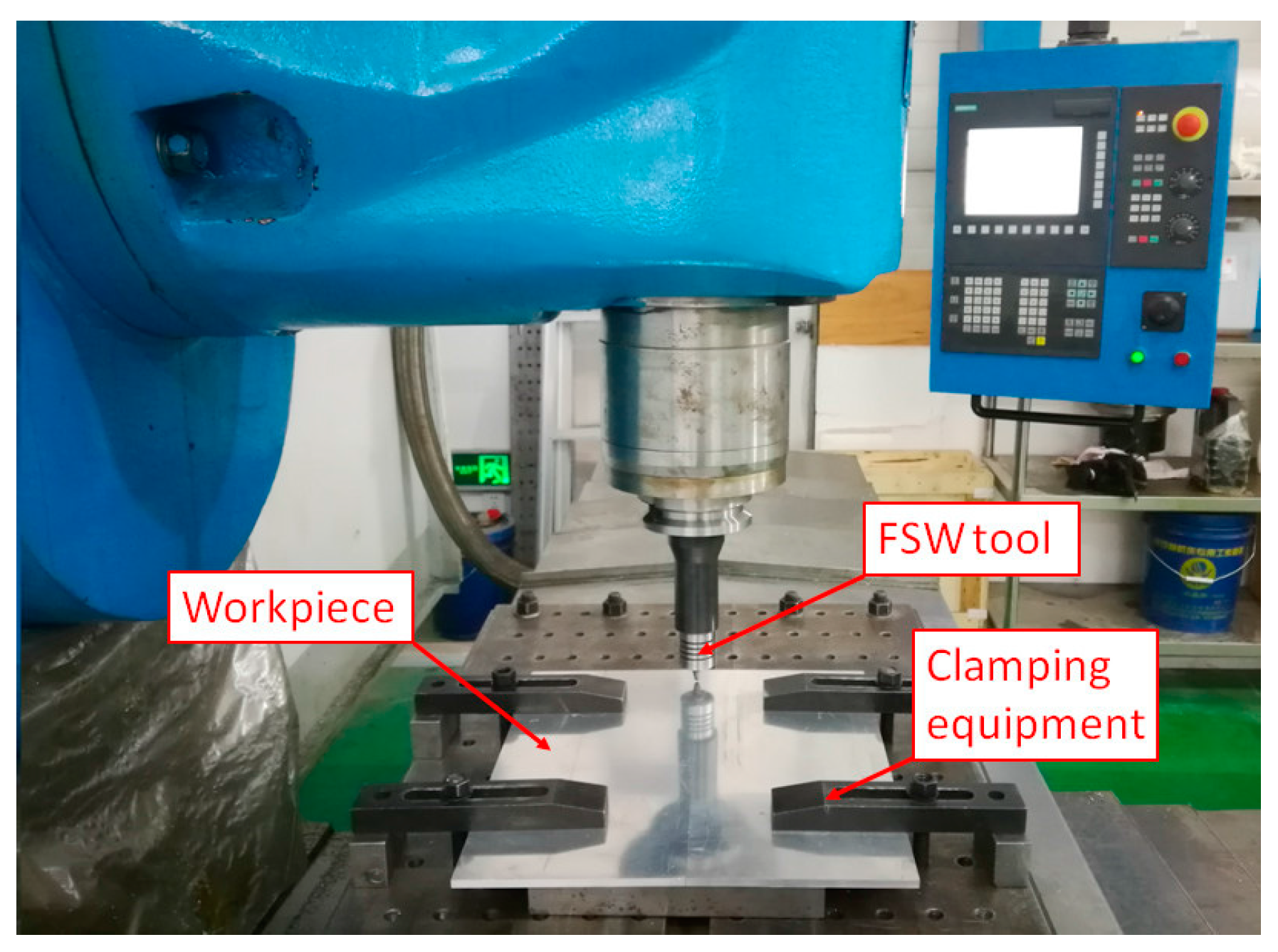
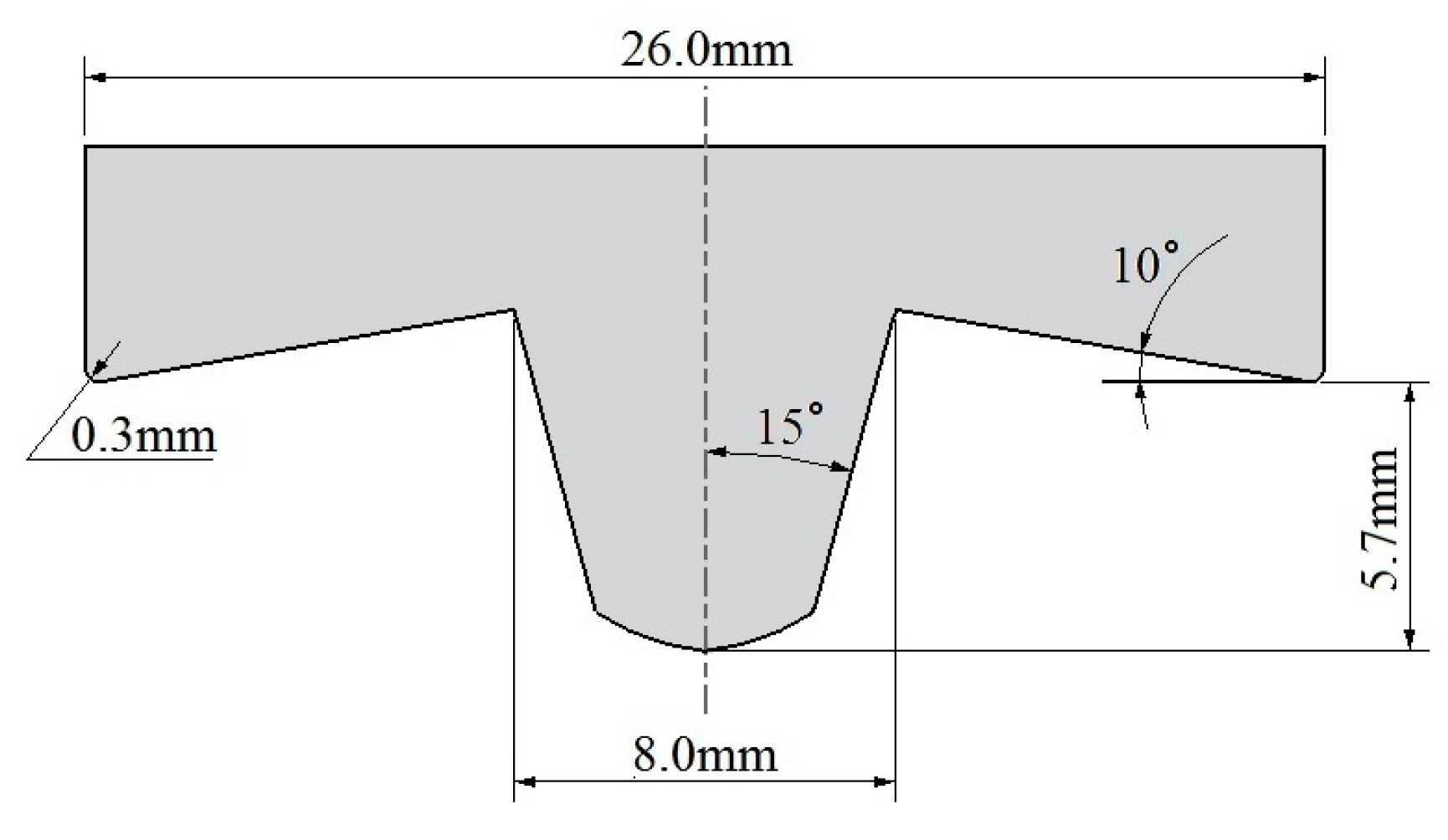
Al6061-T6 aluminum alloy plates (300 mm in length, 150 mm in width and 6 mm in thickness) were friction stir welded on a FSW equipment modified from a universal milling machine (Shenyang Institute of Automation, Chinese Academy of Sciences, Shenyang, China) (Figure 1). A tool with a concave shoulder and a tapered smooth pin, made of W6 alloy, was used, and its cross section profile and main dimensions are shown in Figure 2. In this experiment, position control was applied to the FSW tool. The tool tilt angle was kept constant at 0° and the plunged depth of the shoulder into the workpiece was set to 0 mm during the welding process. The following welding parameters were considered: tool rotational speed was 600 rpm, plunging feed was 3 mm/min and welding speed was 50 mm/min. During the welding experiment, the thermal cycles were measured using K-type thermocouples (Changzhou Jinailian Electronic Technology Co., Ltd, Changzhou, China) embedded into little holes at locations that are 10 mm, 15 mm, 20 mm and 25 mm away from the joint line on both the advancing side (AS) and the retreating side (RS). After welding, the transverse cross-section of the joint was prepared to characterize the macrostructure by optical microscopy.
3. Model Description
A 3D coupled thermo-mechanical finite element model was developed to predict and analyze defect formation during the FSW process based on coupled Eulerian Lagrangian formulation, Coulomb’s frictional law and the Johnson-Cook material law.
3.1. Governing Equations
According to the CEL method, in the present study, the workpiece was modeled under Eulerian framework, while the FSW tool was modeled as a Lagrangian body. It is well known that the conservation equations in the Eulerian description are written using the spatial time derivative. On the other hand, the material time derivative is used in the standard Lagrangian description for solid and structural analysis. The relation between material and spatial time derivatives is:
where ϕ is the arbitrary solution variable, v is the material velocity, and are the material and spatial time derivatives, respectively.
For the FSW problem, the Lagrangian mass, momentum and energy conservation equations transferred into the Eulerian (spatial derivative) conservation equations are given as follows [30]:
where ρ is the density, σ is Cauchy stress, b is the vector of body forces, e is the strain energy, and D is the velocity strain.
In order to solve the problem, Equations (2)–(4) are rewriten to the general form:
where Φ is the flux function, S is the source term. Equation (5) can be divided using operator splitting into two equations [31]:
which are then solved sequentially.
Equation (6), the Lagrangian step, contains the source term, and Equation (7), the Eulerian step, contains the convective term. The difference between Equation (6) and the standard Lagrangian governing equations is the type of the time derivative. Equation (6) is hence identical to the standard Lagrangian formulation if the spatial time derivative is replaced by the material time derivative on the fixed mesh. To solve Equation (7), the deformed mesh is moved to the original fixed mesh, and the volume of material transported between adjacent elements is calculated. The Lagrangian solution variables, such as the mass, energy, momentum, stress and others are then adjusted to account for the flow of the material between adjacent elements by the transport algorithms.
3.2. Geometrical Model and Mesh Generation
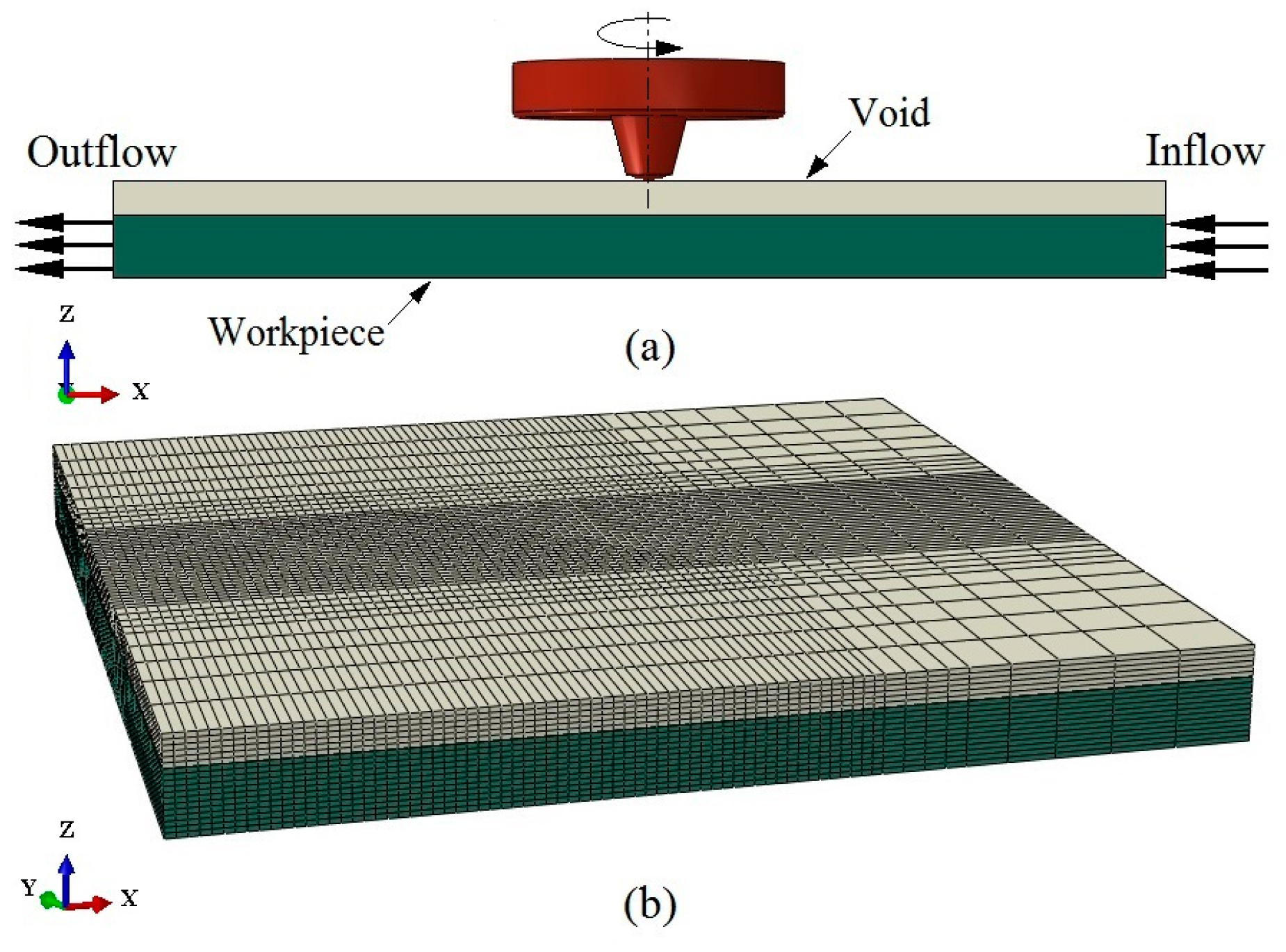
ABAQUS/Explicit [32] was employed to solve the above conservation equations of the FSW process. Due to the low computational efficiency, only a localized region of the workpiece was included in the analysis. The welding phase was simulated by employing control volume approach, whereas the welding speed was defined as inflow and outflow over Eulerian domain boundaries [29], as shown in Figure 3a. The domain size was considered to be four times larger than the tool shoulder diameter [21,23]. This size was a compromise between simulation accuracy and computational time. The Eulerian domain was generated in a cuboidal shape with the size of 100 × 100 × 9 mm3, which is partitioned initially into two zones: workpiece and void (Figure 3a). As mentioned above, the actual workpiece thickness is 6 mm. The domain is thicker than the physical workpiece by 3 mm, which is left initially empty (void) for visualizing flash formation during FSW welding.
The Eulerian domain was meshed with 60,444 thermally coupled 8-node Eulerian elements. In order to keep the material from penetrating the tool surface and to improve the computational efficiency, bias mesh technique was applied to generate fine mesh at the tool-workpiece interaction zone and coarse mesh at the sides (Figure 3b). On the other hand, the FSW tool was considered as an isothermal Lagrangian rigid body. The tool shape and size were similar to those used in the welding experiment, and 4-node 3D bilinear rigid quadrilateral element was employed to mesh the rigid tool surface, as shown in Figure 4.
3.3. Heat Generation Model
Friction stir welding is a complex coupled thermo-mechanical problem. During FSW, heat is generated by friction between tool and workpiece and via plastic deformation [33,34]. Both of them were taken into consideration in the present model.
Plastic deformation heat qpl is produced by inelastic work under sticking condition inside the shear layer of the workpiece, which is the source term in Equation (5) for energy conservation and can be calculated by the following formula:
where η is the thermal conversion efficiency inside the workpiece and 90% of plastic work was considered to be converting into heat in the model. is the plastic strain rate and is the flow stress of the workpiece material.
The friction heat qf due to sliding friction between tool and workpiece is given as follows:
where is the slip rate, and τ is the frictional shear stress. According to the classical Coulomb’s frictional law, τ can be expressed as:
where P is the contact pressure at the tool-workpiece interface and μ is the frictional coefficient.
τ = μP,
As for the frictional coefficient, it is generally accepted that it is related to the tribological and microstructural behaviors of the material to be welded [35]. For FSW, the frictional coefficient is usually defined as a function of slip rate, contact pressure and surface temperature. However, due to the very complex process of FSW, the accurate values of the frictional coefficient are still indeterminate, and cannot be estimated by any straightforward methods so far [33]. For this reason, a variety of friction coefficient values have been found in the literature, with the majority of them being a constant value. Tutunchilar S. et al. [36] used frictional coefficients of 0.4, 0.5 and 0.6 under 100 mm/min transverse speed and 900 rpm rotational speed. Buffa G. et al. [37] also used a constant friction factor of 0.46 between workpiece and tool. In the present study, a frictional coefficient of 0.58, similar to that of Al-Badour F. et al. [29], was considered for all simulation conditions.
3.4. Boundary Conditions
3.4.1. Thermal Boundary Conditions
During FSW, part of the heat is dissipated into the air from the top surface of the workpiece by convection and radiation, and the corresponding heat transfer boundary condition is given by:
where nS is the normal direction of heat dissipation surface, σb is the Stefan-Boltzmann constant, εb is the emissivity, Ta is the ambient temperature, and hcon is the convective heat transfer coefficient. In this study, emissivity of 0.09 was employed for Al6061-T6 [38]. The value of hcon was set as 10 W/m2·°C with the ambient temperature of 25 °C similar to that of Schmidt H. and Hattel J. [21] and Darko M.V. et al. [39].
In addition to convection and radiation heat transfer, the bottom surface of the workpiece is in contact with the backing plate and the rest of the heat is transferred into the backing plate during the FSW process. Due to the complexity of the contact heat transfer problem, it was usually simplified to convection heat transfer in many previous simulations, which obtained good agreement between the simulated temperature and the experimental data [39,40,41]. In the present analysis, the same approach was adopted. The equivalent convective heat transfer coefficient was considered as a function of temperature and its value can be found in literature [40].
3.4.2. Velocity Boundary Conditions
As mentioned earlier, due to low computational efficiency, only a localized region of the workpiece was included in the analysis and the welding phase was simulated using a control volume approach. For convenience, a reference point was set on the axis of the FSW tool to control its motion precisely. The longitudinal motion of the FSW tool was not considered explicitly. Instead, the longitudinal velocity of the tool was set to zero and the workpiece material was allowed to flow through the Eulerian domain with an overall longitudinal velocity equal to negative of the tool translational velocity (welding speed). This was accomplished through the use of the appropriate inflow and outflow velocity boundary conditions over the vertical faces of the Eulerian domain which are orthogonal to the direction of tool travel. In addition, the top surface of the workpiece was free and displacement constraints were applied on the boundaries in order to avoid material escaping from the sides and the bottom surface of Eulerian domain. Figure 5 illustrates schematically the velocity boundary conditions used in the present model. The welding process conditions used in the model, including the tool rotational speed, plunging feed, welding speed, tool tilt angle and plunged depth, are exactly the same as those in the welding experiment.
3.5. Material Model
In the welding nugget zone (WNZ) and thermo-mechanically affected zone (TMAZ), a very large plastic deformation takes place during the FSW process. The interaction of flow stress with temperature, plastic strain and strain rate is essential for modeling the FSW process. For this reason, Johnson-Cook material law [42] was employed to describe the plasticity of workpiece material and the flow stress σfs (Equation (8)) is defined as follow:
where is the equivalent plastic strain, is the equivalent plastic strain rate, is the normalizing strain rate, and A, B, C, n and m are material constants. The exponent n denotes the strain hardening effect, while m models the high temperature softening effect. C represents the strain rate sensitivity, parameters A, B and n are evaluated by experiment at temperature Tref, Tmelt is the material solidus temperature.
4. FE Results and Discussion
4.1. Verification of FE Model
As mentioned earlier, the finite element model is validated using experimentally measured temperature as well as by matching the estimated processed zone shape and void size with those obtained experimentally.
Figure 6 shows the simulated temperature field during the steady-state welding process. It can be seen clearly that the temperature distribution is asymmetrical around the weld centerline, which is caused by the non-uniform material flow around the tool. The high temperature region locates under the shoulder, where the energy density is extremely high. The peak temperature locates at the position of the advancing side behind the tool, and its value 514 °C is about 88% of the melting temperature (583 °C) of Al6061-T6 aluminum alloys. It should be noted that the temperature distribution characteristics above are similar to those in the literature [44].
Figure 7 compares the results predicted and the data measured for the peak temperature distribution along the vertical direction of the weld. It is observed that the simulated peak temperatures are slightly higher than the experimental ones. The difference may be due to the material parameters used in the numerical simulation, assumption of constant frictional coefficient and simplification of thermal boundary conditions. In addition, the measurement error of the temperature field will also affect the accuracy of the simulation results. It is worth noting that, although there is a discrepancy between the simulated temperature and the data measured, generally speaking they are still in good agreement with each other.
Further validation is performed by comparing the estimated equivalent plastic strain zone to the microstructure of the processed zone obtained experimentally, as shown in Figure 8. The results compared reveal that the estimated equivalent plastic strain zone shape is in good agreement with the microstructure of the processed zone obtained experimentally. Moreover, the developed finite element model can predict the presence of void in the weld quite accurately (Figure 8). However, the model is found to overestimate the void size. The estimated size of void is 2.18 mm × 0.55 mm, while the result measured is 1.09 mm × 0.7 mm. Many reasons may lead to this discrepancy, such as the assumption of a constant frictional coefficient in the contact model, the simplification of the contact heat transfer between workpiece and backing plate, as well as other idealizations in the model.
4.2. Effect of Welding Parameters
It is well known that welding speed and tool rotational speed are the two welding parameters which have an important influence on the material flow in the weld and the defect formation during FSW process. In this investigation, both conditions were simulated using the develop FE model.
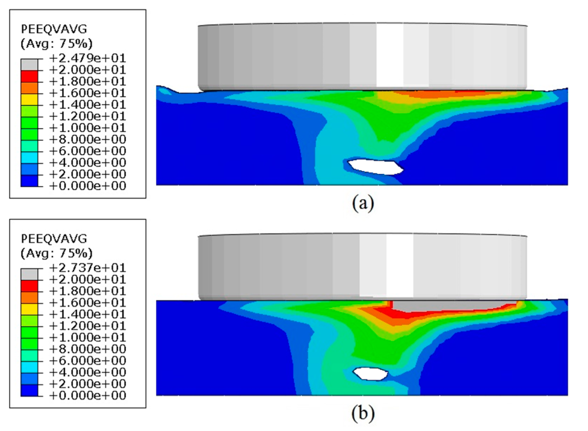
Effect of welding speed: two welding speeds of 50 mm/min and 150 mm/min have been selected to investigate the welding speed effect on equivalent plastic strain and void formation. The results compared are illustrated in Figure 9. It can been seen that the estimated equivalent plastic strain values increase when the welding speed is reduced. The high plasticized zones under the tool shoulder are found to be larger for lower welding speed. Moreover, welding at the welding speed of 50 mm/min produces a smaller void near the tip of FSW tool pin. However, the welding speed only has a limited effect on void size (Figure 9). These findings are similar to those reported by Al-Badour F. et al. [29].
Effect of tool rotational speed: two tool rotational speeds of 400 rpm and 800 rpm have been selected to study the tool rotational speed effect on equivalent plastic strain and void formation as illustrated in Figure 10. The results compared show that the estimated equivalent plastic strain values increase when the tool rotational speed is increased. The high plasticized zone under the tool shoulder is found to be larger for higher tool rotational speeds. In addition, welding at high tool rotational speeds produces a smaller void.
The presence of a larger plastic zone and smaller void size at lower welding speeds or higher tool rotational speeds could be attributed to the increase in heat input leading to easier material flow.
Based on the analysis compared above, it can be drawn that welding at low welding speed or high tool rotational speed is benefit to reduce void size.
4.3. Effect of Tool Pin Profile
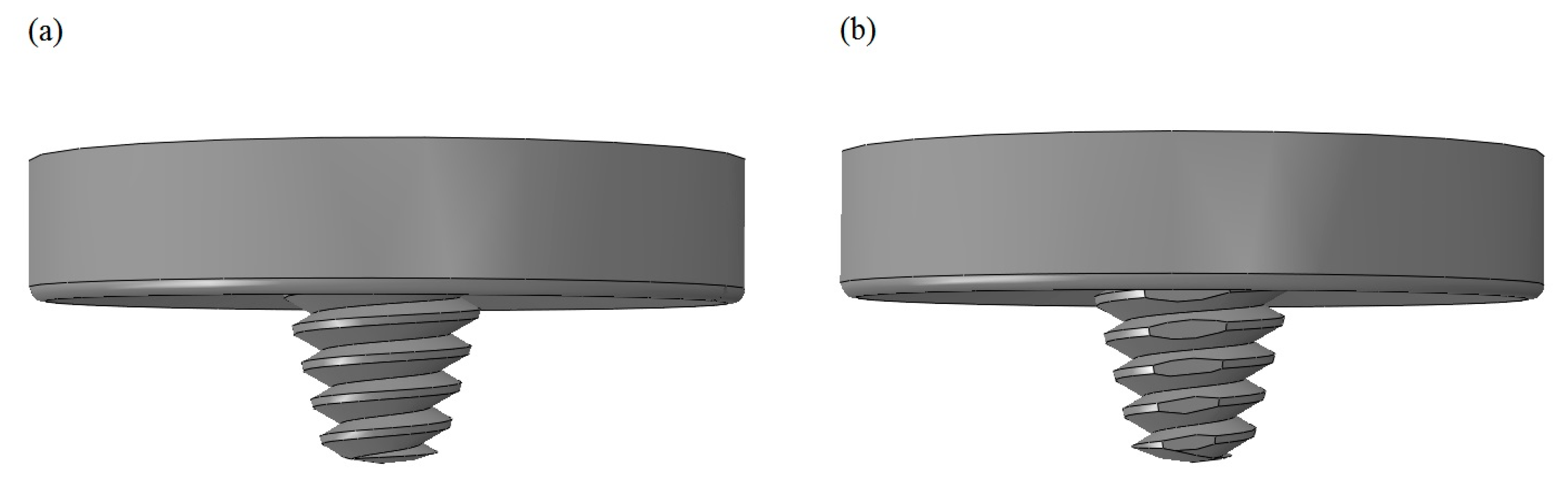
It is well known that material flow during FSW is affected by tool pin profile. The tool pin features such as threads, flats, or flutes may enhance the material flow in the weld and lead to better material mixing and eventually better weld strength. In this investigation, three different tool pins have been selected to study the effects of tool pin profile on the material flow and void formation during the FSW process. Simulations are conducted for a smooth tool pin, a threaded tool pin and a threaded tri-flat tool pin, each using their dedicated solid models respectively. Figure 11 illustrates schematically the FSW tools with featured pins in 3D.
The effects of tool pin profile on the equivalent plastic strain in the weld and on void formation are illustrated in Figure 12. It can be seen clearly that the equivalent plastic strain values for welds performed with a smooth tool pin (Figure 12a) are smaller than those developed using featured tool pins (Figure 12b,c). When featured tool pins are used, no sign of the nucleation of voids or volumetric defects are found in the weld. However, using a smooth tool pin leads to volumetric defect formation. Similar results can be found in the literature [38].
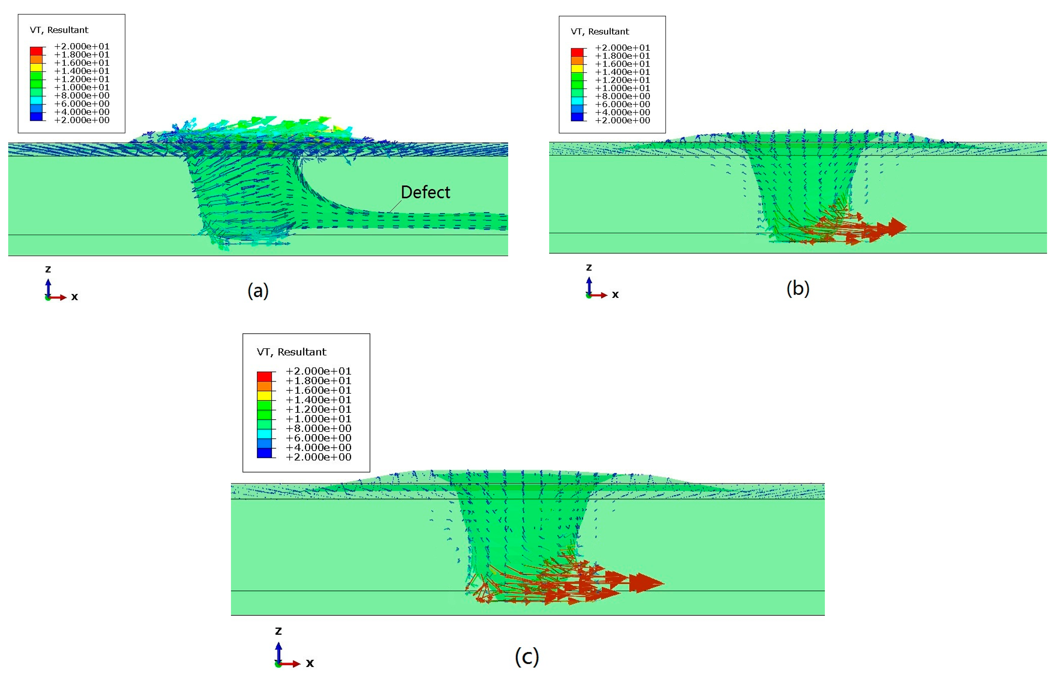
Figure 13 shows the material velocity around the welding tool during the FSW process. It can be seen that the material velocity around the FSW tool is found to be higher for welds performed with featured tool pins. Moreover, compared with a smooth tool pin, featured tool pins produce better material flow along the axial direction of the tool pin, which contributes to reducing defect size and achieving defect-free weldment.
5. Conclusions
In the present work, a 3D coupled thermo-mechanical finite element model is established, based on the CEL method to simulate the FSW process of Al6061-T6. The model is implemented in Abaqus explicit environment and validated by matching the simulated temperature, estimated processed zone shape and void size with those obtained experimentally. The effects of welding parameters and tool pin profile on material flow in the weld and void formation are also investigated and the conclusions of significance are drawn as follows:
- The model can predict the plasticized zone shape and the presence of void in the weld quite accurately. However, the void size is overestimated.
- The void size is directly affected by welding parameters. Welding at low welding speed or high tool rotational speed could produce a smaller void.
- Compared with a smooth tool pin, a featured tool pin can enhance plastic flow in the weld, which contributes to reducing defect size and achieving defect-free weldment.
Acknowledgments
The authors are grateful to be supported financially by the National Natural Science Foundation of China (Grant No. 51505471).
Author Contributions
Zhi Zhu and Min Wang developed the CEL model of friction stir welding process and wrote the paper; Huijie Zhang and Xiao Zhang designed and performed the friction stir welding experiments; Tao Yu and Zhenqiang Wu analyzed the data and modified the paper.
Conflicts of Interest
The authors declare no conflict of interest.
References
- Thomas, W.M.; Nicholas, E.D.; Needham, J.C.; Murch, M.G.; Temple-Smith, P.; Dawes, C.J. Friction Stir Butt Welding. International Patent Application No. PCT/GB9202203, GB Patent Application No. 9125978.8. U.S. Patent Application No. 5460317 A, 6 December 1991. [Google Scholar]
- Zhao, J.; Jiang, F.; Jian, H.G.; Wen, K.; Jiang, L.; Chen, X. Comparative investigation of tungsten inert gas and friction stir welding characteristics of Al-Mg-Sc alloy plates. Mater. Des. 2010, 31, 306–311. [Google Scholar] [CrossRef]
- Cavaliere, P.; Cabibbo, M.; Panella, F.; Squillace, A. 2198 Al-Li plates jointed by friction stir welding: Mechanical and microstructural behavior. Mater. Des. 2009, 30, 3622–3631. [Google Scholar] [CrossRef]
- Thomas, W.M.; Nicholas, E.D. Friction stir welding for the transportation industries. Mater. Des. 1997, 18, 269–273. [Google Scholar] [CrossRef]
- He, X. Thermo-mechanical modelling of friction stir welding process. Adv. Mater. Res. 2013, 774, 1155–1159. [Google Scholar] [CrossRef]
- Colligan, K. Material flow behavior during friction stir welding of aluminum. Weld. J. 1999, 172, 229–237. [Google Scholar]
- Seidel, T.U.; Reynolds, A.P. Visualization of the material flow in AA2195 friction-stir welds using a marker insert technique. Metall. Mater. Trans. A 2001, 32, 2879–2884. [Google Scholar] [CrossRef]
- Schmidt, H.N.B.; Dickerson, T.L.; Hattel, J.H. Material flow in butt friction stir welds in AA2024-T3. Acta Mater. 2006, 54, 1199–1209. [Google Scholar] [CrossRef]
- Ouyang, J.H.; Kovacevic, R. Material flow and microstructure in the friction stir butt welds of the same and dissimilar aluminum alloys. J. Mater. Eng. Perform. 2002, 11, 51–63. [Google Scholar] [CrossRef]
- Lee, W.B.; Yeon, Y.M.; Jung, S.B. The joint properties of dissimilar formed Al alloys by friction stir welding according to the fixed location of materials. Scr. Mater. 2003, 49, 423–428. [Google Scholar] [CrossRef]
- Krishnan, K.N. On the formation of onion rings in friction stir welds. Mater. Sci. Eng. A 2002, 327, 246–251. [Google Scholar] [CrossRef]
- Sutton, M.A.; Yang, B.; Reynolds, A.P.; Taylor, R. Microstructural studies of friction stir welds in 2024-T3 aluminum. Mater. Sci. Eng. A 2002, 323, 160–166. [Google Scholar] [CrossRef]
- Seidel, T.U.; Reynolds, A.P. Two-dimensional friction stir welding process model based on fluid mechanics. Sci. Technol. Weld. Join. 2003, 8, 175–183. [Google Scholar] [CrossRef]
- Ulysse, P. Three-dimensional modeling of the friction stir-welding process. Int. J. Mach. Tools Manuf. 2002, 42, 1549–1557. [Google Scholar] [CrossRef]
- Colegrove, P.A.; Shercliff, H.R. Development of the Trivex friction stir welding tool: Part II-3-Dimensional flow modelling. Sci. Technol. Weld. Join. 2004, 9, 352–361. [Google Scholar] [CrossRef]
- Colegrove, P.A.; Shercliff, H.R. 3-Dimensional CFD modelling of flow round a threaded friction stir welding tool profile. J. Mater. Process. Technol. 2005, 169, 320–327. [Google Scholar] [CrossRef]
- Long, T.; Reynolds, A.P. Parametric studies of friction stir welding by commercial fluid dynamics simulation. Sci. Technol. Weld. Join. 2013, 11, 200–208. [Google Scholar] [CrossRef]
- Carlone, P.; Palazzo, G.S. Influence of process parameters on microstructure and mechanical properties in AA2024-T3 friction stir welding. Metall. Microstruct. Anal. 2013, 2, 213–222. [Google Scholar] [CrossRef]
- Deng, X.; Xu, S. Two-dimensional finite element simulation of material flow in the friction stir welding process. J. Manuf. Process. 2004, 6, 125–133. [Google Scholar] [CrossRef]
- Zhang, H.W.; Zhang, Z.; Chen, J.T. 3D modeling of material flow in friction stir welding under different process parameters. J. Mater. Process. Technol. 2007, 183, 62–70. [Google Scholar] [CrossRef]
- Schmidt, H.; Hattel, J. A local model for the thermomechanical conditions in friction stir welding. Model. Simul. Mater. Sci. Eng. 2005, 13, 77–93. [Google Scholar] [CrossRef]
- Guerdoux, S.; Fourment, L. A 3D numerical simulation of different phases of friction stir welding. Model. Simul. Mater. Sci. Eng. 2009, 17, 075001. [Google Scholar] [CrossRef]
- Zhang, Z.; Zhang, H.W. Numerical studies on controlling of process parameters in friction stir welding. J. Mater. Process. Technol. 2009, 209, 241–270. [Google Scholar] [CrossRef]
- Buffa, G.; Hua, J.; Shivpuri, R.; Fratini, L. Design of the friction stir welding tool using the continuum based FEM model. Mater. Sci. Eng. A 2006, 419, 381–388. [Google Scholar] [CrossRef]
- Assidi, M.; Fourment, L. Accurate 3D friction stir welding simulation tool based on friction model calibration. Int. J. Mater. Form. 2009, 2, 327–330. [Google Scholar] [CrossRef]
- Dialami, N.; Chiumenti, M.; Cervera, M.; de Saracibar, C.A. An apropos kinematic framework for the numerical modelling of Friction Stir Welding. Comput. Struct. 2013, 117, 48–57. [Google Scholar] [CrossRef]
- Bussetta, P.; Dialami, N.; Boman, R.; Chiumenti, M.; de Saracibar, C.A.; Cervera, M.; Ponthot, J.-P. Comparison of a fluid and a solid approach for the numerical simulation of friction stir welding with a non-cylindrical pin. Steel Res. Int. 2014, 85, 968–979. [Google Scholar] [CrossRef]
- Noh, W.F. CEL: A time-dependent, two-space-dimensional, coupled eulerian-lagrange code. Methods Comput. Phys. 1964, 3, 117–179. [Google Scholar]
- Al-Badour, F.; Merah, N.; Shuaib, A.; Bazoune, A. Coupled Eulerian Lagrangian finite element modeling of friction stir welding processes. J. Mater. Process. Technol. 2013, 213, 1433–1439. [Google Scholar] [CrossRef]
- Benson, D.J.; Okazawa, S. Contact in a multi-material Eulerian finite element formulation. Comput. Methods Appl. Mech. Eng. 2004, 193, 4277–4298. [Google Scholar] [CrossRef]
- Benson, D.J. A mixture theory for contact in multi-material Eulerian formulations. Comput. Methods Appl. Mech. Eng. 1997, 140, 59–86. [Google Scholar] [CrossRef]
- Dassault Systemes. Abaqus 6.12 Documentation; Dassault Systemes Simulia Corp.: Providence, RI, USA, 2012. [Google Scholar]
- Nandan, R.; Debroy, T.; Bhadeshia, H.K.D.H. Recent advances in friction-stir welding-Process, weldment structure and properties. Prog. Mater. Sci. 2008, 53, 980–1023. [Google Scholar] [CrossRef]
- Mishra, R.S.; Ma, Z.Y. Friction stir welding and processing. Mater. Sci. Eng. R Rep. 2005, 50, 1–78. [Google Scholar] [CrossRef]
- Zahmatkesh, B.; Enayati, M.H.; Karimzadeh, F. Tribological and microstructural evaluation of friction stir processed Al2024 alloy. Mater. Des. 2010, 31, 4891–4896. [Google Scholar] [CrossRef]
- Tutunchilar, S.; Haghpanahi, M.; Givi, M.K.B.; Asadi, P.; Bahemmat, P. Simulation of material flow in friction stir processing of a cast Al-Si alloy. Mater. Des. 2012, 40, 415–426. [Google Scholar] [CrossRef]
- Buffa, G.; Campanile, G.; Fratini, L.; Prisco, A. Friction stir welding of lap joints: Influence of process parameters on the metallurgical and mechanical properties. Mater. Sci. Eng. A 2009, 519, 19–26. [Google Scholar] [CrossRef]
- Al-Badour, F.; Merah, N.; Shuaib, A.; Bazoune, A. Thermo-mechanical finite element model of friction stir welding of dissimilar alloys. Int. J. Adv. Manuf. Technol. 2014, 72, 607–617. [Google Scholar] [CrossRef]
- Veljić, D.M.; Sedmak, A.S.; Rakin, M.P.; BAJIĆ, N.S.; Medjo, B.I.; Bajić, D.R.; Grabulov, V.K. Experimental and numerical thermo-mechanical analysis of friction stir welding of high-strength alluminium alloy. Therm. Sci. 2014, 18, 29–39. [Google Scholar] [CrossRef]
- Zhang, Z.H.; Li, W.Y.; Han, J.; Li, J.L. Numerical analysis of joint temperature evolution during friction stir welding based on plastic deformation heat. China Weld. 2011, 20, 76–80. [Google Scholar]
- Li, H.; Mackenzie, D. Parametric finite-element studies on the effect of tool shape in friction stir welding. Proc. Inst. Mech. Eng. Part B J. Eng. Manuf. 2010, 224, 1161–1173. [Google Scholar] [CrossRef]
- Johnson, G.R.; Cook, W.H. A constitutive model and data for metals subjected to large strains, high strain rates and high temperatures. In Proceedings of the 7th International Symposium on Ballistics, Hague, The Netherlands, 19–21 April 1983; pp. 541–547. [Google Scholar]
- Soundararajan, V.; Zekovic, S.; Kovacevic, R. Thermo-mechanical model with adaptive boundary conditions for friction stir welding of Al 6061. Int. J. Mach. Tools Manuf. 2005, 45, 1577–1587. [Google Scholar] [CrossRef]
- Su, H.; Wu, C.S.; Pittner, A.; Rethmeier, M. Thermal energy generation and disribution in friction stir welding of aluminum alloys. Energy 2014, 77, 720–731. [Google Scholar] [CrossRef]
Figure 1.
Friction stir welding (FSW) experimental system.

Figure 2.
Geometry and dimensions of FSW tool.

Figure 3.
(a) Geometrical model; and (b) finite element mesh for workpiece.

Figure 4.
Finite element mesh for the FSW tool.
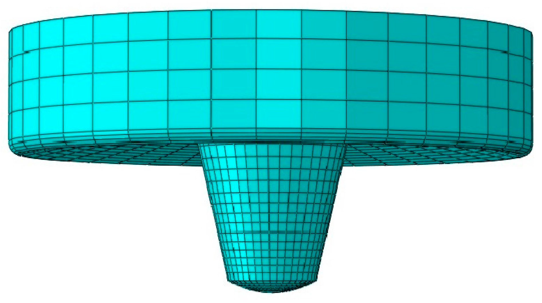
Figure 5.
Velocity boundary conditions.
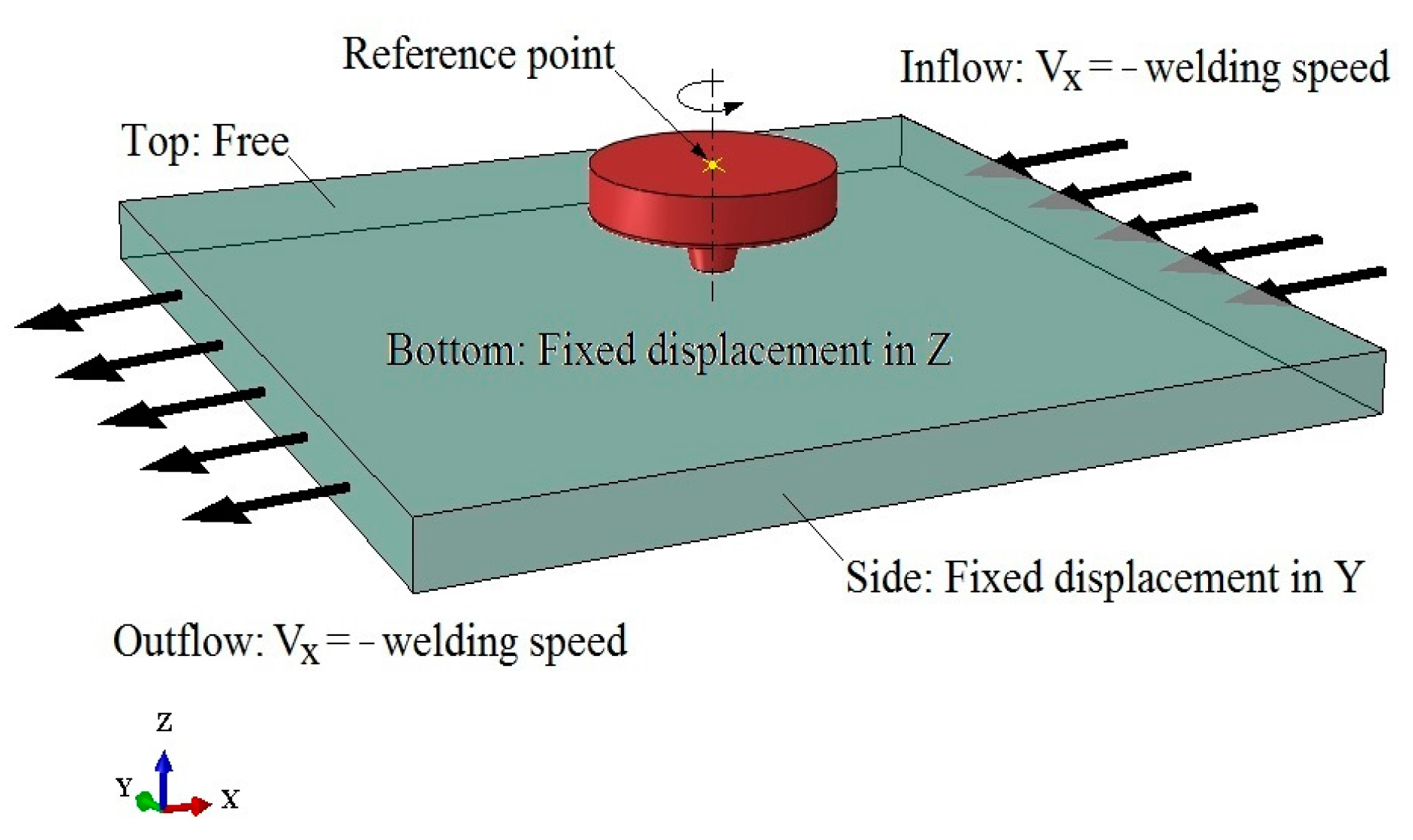
Figure 6.
Simulated temperature field during the steady-state FSW process.
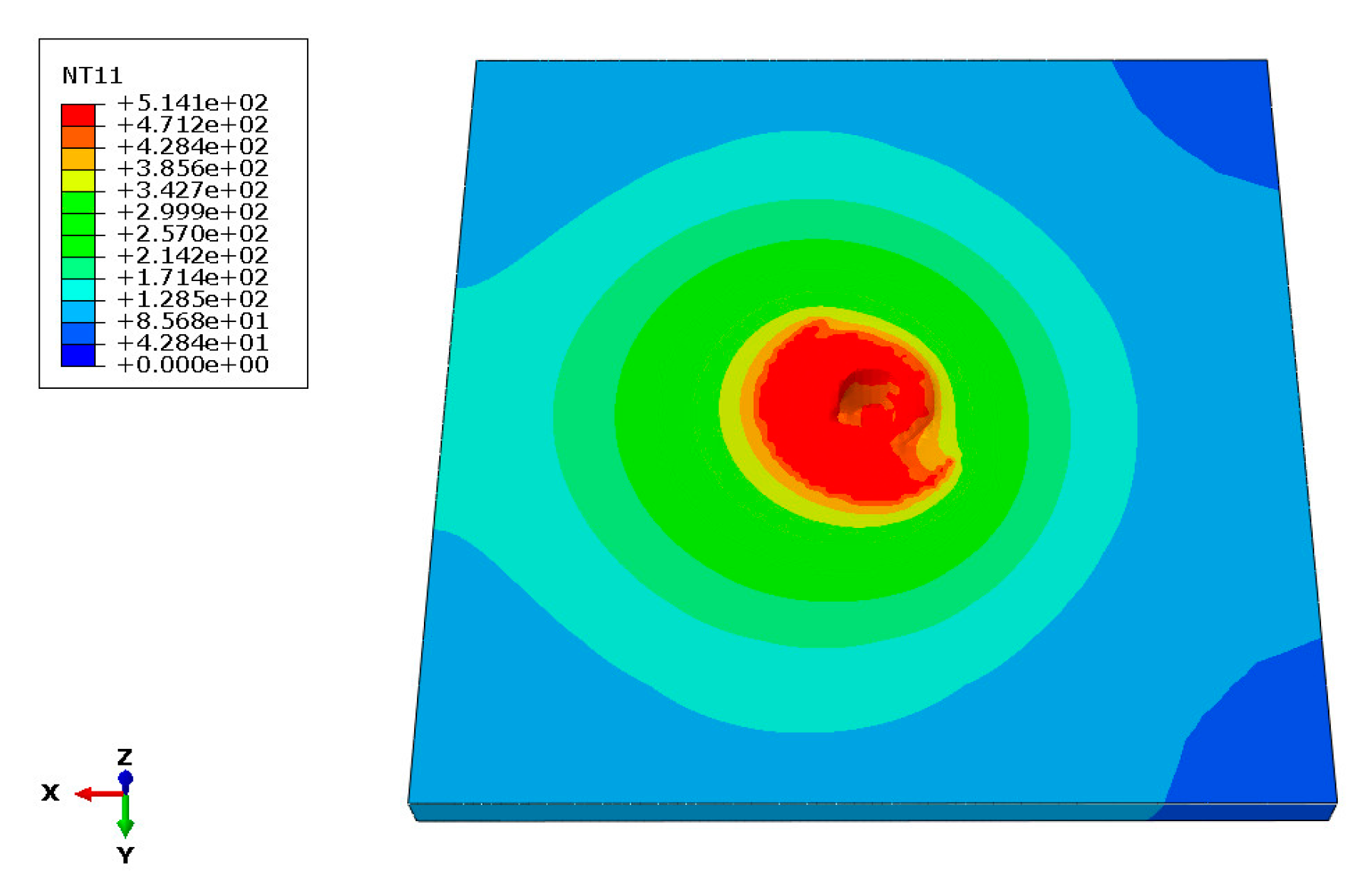
Figure 7.
Comparison between calculated and experimental peak temperature of measured points.
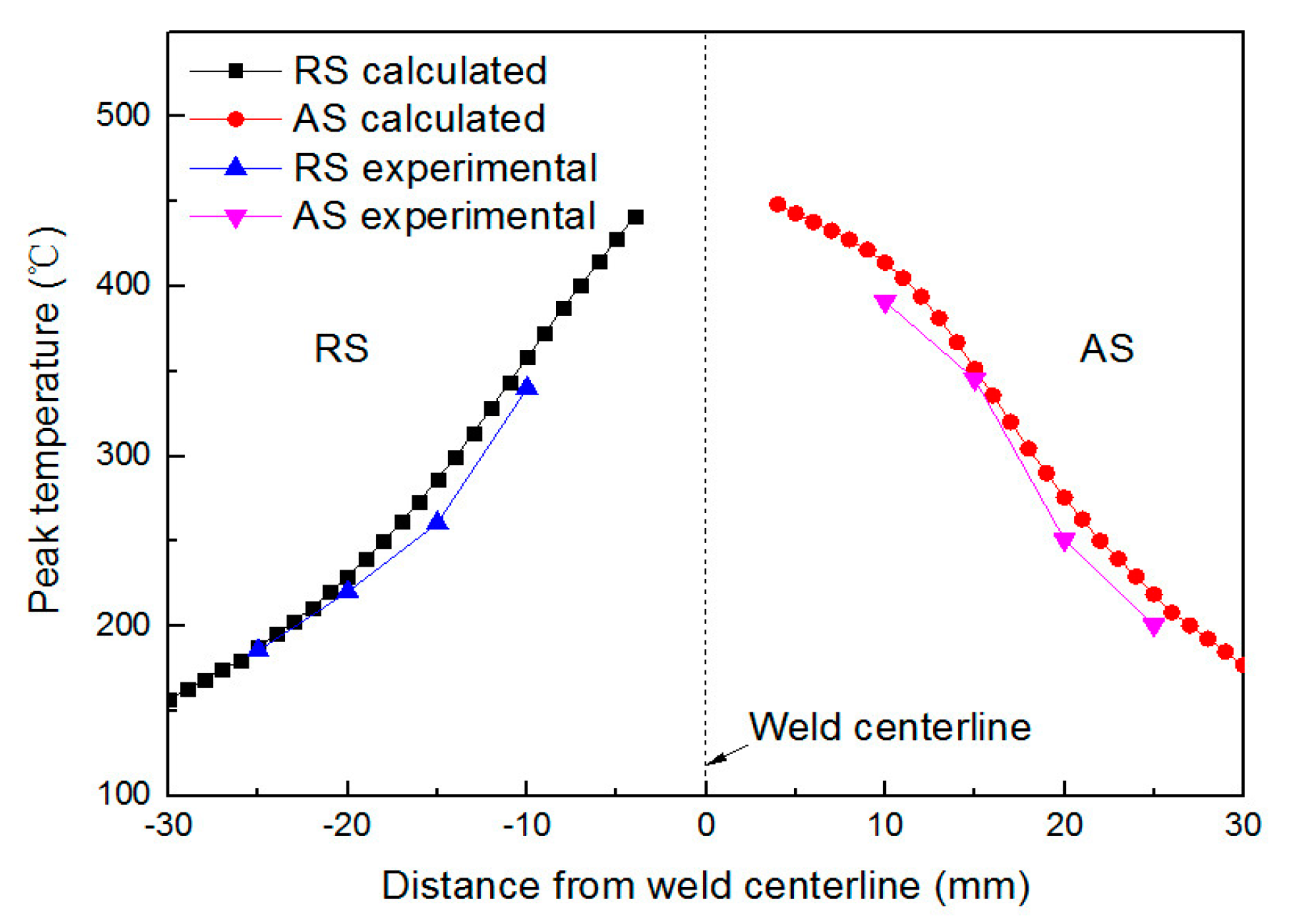
Figure 8.
Matching estimated equivalent plastic strain and void with experimentally found.
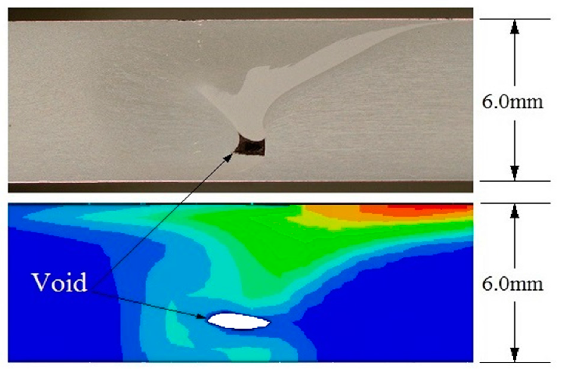
Figure 9.
Equivalent plastic strain and void for (a) 50 mm/min; and (b) 150 mm/min.

Figure 10.
Equivalent plastic strain and void for (a) 400 rpm; and (b) 800 rpm.

Figure 11.
3D representation of FSW tool with (a) threaded pin; and (b) threaded tri-flat pin.

Figure 12.
Equivalent plastic strain and void for (a) smooth tool pin; (b) threaded tool pin; and (c) threaded tri-flat tool pin.
Figure 12.
Equivalent plastic strain and void for (a) smooth tool pin; (b) threaded tool pin; and (c) threaded tri-flat tool pin.
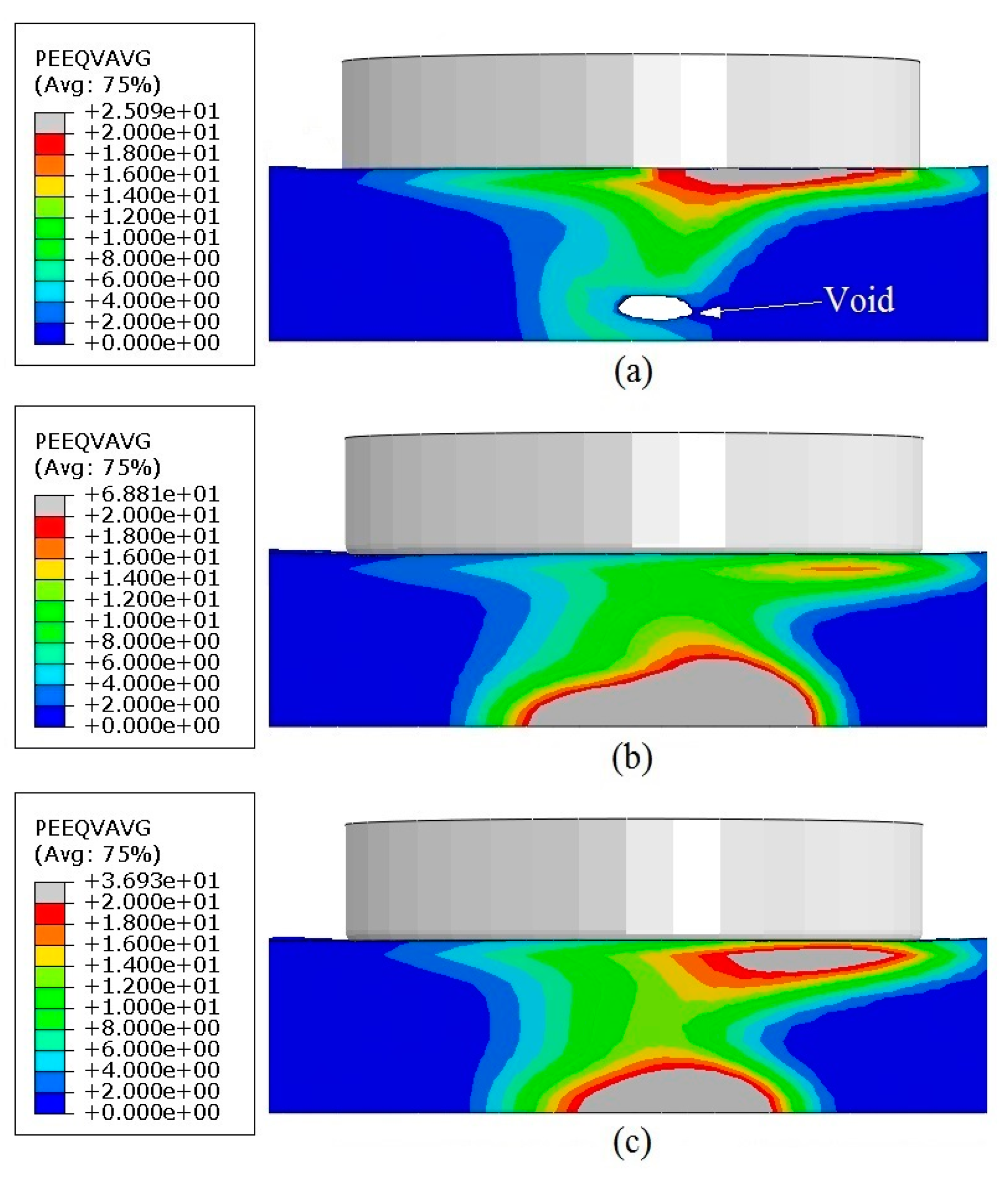
Figure 13.
Weld material velocity profiles around the FSW tool: (a) smooth tool pin; (b) threaded tool pin; and (c) threaded tri-flat tool pin; velocity in mm/s.
Figure 13.
Weld material velocity profiles around the FSW tool: (a) smooth tool pin; (b) threaded tool pin; and (c) threaded tri-flat tool pin; velocity in mm/s.

Table 1.
Temperature-dependent material properties for Al6061-T6.
| T [°C] | ρ [kg m−3] | E [GPa] | v | α [10−6·°C−1] | CP [J kg−1·°C−1] | λ [W m−1·°C−1] |
|---|---|---|---|---|---|---|
| 25 | 2690 | 66.94 | 0.33 | 23.5 | 945 | 167 |
| 100 | 2690 | 63.21 | 0.334 | 24.6 | 978 | 177 |
| 149 | 2670 | 61.32 | 0.335 | 25.7 | 1000 | 184 |
| 204 | 2660 | 56.8 | 0.336 | 26.6 | 1030 | 192 |
| 260 | 2660 | 51.15 | 0.338 | 27.6 | 1052 | 201 |
| 316 | 2630 | 47.17 | 0.36 | 28.5 | 1080 | 207 |
| 371 | 2630 | 43.51 | 0.4 | 29.6 | 1100 | 217 |
| 427 | 2600 | 28.77 | 0.41 | 30.7 | 1130 | 223 |
| 482 | - | 20.2 | 0.42 | - | 1276 | - |
Table 2.
Johnson-Cook constitutive model constants for Al6061-T6.
| A [MPa] | B [MPa] | C | n | m | Tref [°C] | Tmelt [°C] | |
|---|---|---|---|---|---|---|---|
| 324 | 114 | 0.002 | 0.42 | 1.34 | 24 | 583 | 1.0 |
© 2017 by the authors. Licensee MDPI, Basel, Switzerland. This article is an open access article distributed under the terms and conditions of the Creative Commons Attribution (CC BY) license (http://creativecommons.org/licenses/by/4.0/).
Share and Cite
MDPI and ACS Style
Zhu, Z.; Wang, M.; Zhang, H.; Zhang, X.; Yu, T.; Wu, Z. A Finite Element Model to Simulate Defect Formation during Friction Stir Welding. Metals 2017, 7, 256. https://doi.org/10.3390/met7070256
AMA Style
Zhu Z, Wang M, Zhang H, Zhang X, Yu T, Wu Z. A Finite Element Model to Simulate Defect Formation during Friction Stir Welding. Metals. 2017; 7(7):256. https://doi.org/10.3390/met7070256
Chicago/Turabian StyleZhu, Zhi, Min Wang, Huijie Zhang, Xiao Zhang, Tao Yu, and Zhenqiang Wu. 2017. "A Finite Element Model to Simulate Defect Formation during Friction Stir Welding" Metals 7, no. 7: 256. https://doi.org/10.3390/met7070256
Note that from the first issue of 2016, this journal uses article numbers instead of page numbers. See further details here.