
Effect of Current on Structure and Macrosegregation in Dual Alloy Ingot Processed by Electroslag Remelting

1
The State Key Laboratory of Refractories and Metallurgy, Wuhan University of Science and Technology, Wuhan 430081, China
2
Key Laboratory for Ferrous Metallurgy and Resources Utilization of Ministry of Education, Wuhan University of Science and Technology, Wuhan 430081, China
3
Collaborative Innovation Center of Steel Technology, University of Science and Technology Beijing, Beijing 100083, China
4
School of Metallurgy, Northeastern University, Shenyang 110004, China
*
Author to whom correspondence should be addressed.
Metals 2017, 7(6), 185; https://doi.org/10.3390/met7060185
Submission received: 6 April 2017
/
Revised: 10 May 2017
/
Accepted: 13 May 2017
/
Published: 24 May 2017
(This article belongs to the Special Issue Alloy Steels)
Abstract
:Macrosegregation is a very common problem for the quality control of all cast ingots. The effect of current on the structure and macrosegregation in dual alloy ingot processed by electroslag remelting (ESR) was investigated experimentally with various analytical methods. In this study, the electrode consisted of NiCrMoV alloy bar (upper part) and CrMoV alloy (lower part) with a diameter of 55 mm, was remelted in a laboratory-scale ESR furnace with the slag containing 30 mass pct alumina and 70 mass pct calcium fluoride under an open air atmosphere. The results show that the macrostructures of three ingots processed by electroslagremelting with different currents are nearly similar. The thin equiaxed grains region and the columnar grains region are formed under the ingot surface, the latter region is the dominant part of the ingot. The typical columnar structure shows no discontinuity among the NiCrMoV alloy zone, the CrMoV alloy zone, and the transition zone in three ingots. With the increase of the current, the grain growth angle increases due to the deeper molten metal pool. The secondary dendrite arm spacing (SDAS) firstly decreases, then increases. The SDAS is dominated by the combined effect of the local solidification rate and the width of mushy region. With the current increasing from 1500 A to 1800 A and 2100 A, the width of the transition zone decreases from 147 mm to 115 mm and 102 mm. The macrosegregation becomes more severe due to the fiercer flows forced by the Lorentz force and the thermal buoyancy force. The cooling rate firstly increases, then decreases, due to the effect of the flows between the mushy region and metal pool and the temperature gradient at the mushy zone of the solidification front. With a current of 1800 A, the SDAS is the smallest and cooling rate is the fastest, indicating that less dendrite segregation and finer precipitates exist in the ingot. Under the comprehensive consideration, the dual alloy ingot processed by the ESR with a current of 1800 A is the best because it has the smallest SDAS, the appropriate grain growth angle, moderate macrosegregation and thickness of the transition zone.
1. Introduction
With the wide application of the single-cylinder steam turbine using combined cycle, the power generation efficiency has been greatly improved. The rotor made of traditional bolted high/intermediate pressure-low pressure shaft has been unable to meet the increasing demand for power generation efficiency. Compared with the conventional bolted shaft parts, the dual alloy single shaft significantly improves power generation efficiency. Such a dual alloy shaft can be manufactured by welding, however, it requires a long production cycle [1]. Numerous creep tests indicate that elevated temperature and high pressure have a fatal impact on the life of the material due to the degradation of material structure during service under harsh conditions [2,3,4]. In order to improve the dual alloy single shaft quality and yield, ESR can be applied to produce dual alloy shaft. During the ESR manufacture process, two pre-melted rods containing different alloy compositions are joined into a single electrode by welding, and then the single electrode is remelted by ESR technology [1].
ESR is a combined process for steel melting, refining and casting. The molten slag is added into the water-cooled copper mold, and then the electrode is inserted into the molten slag. The alternating current passing through the loop creates Joule heating in the highly resistive molten slag. The electrode is heated to melt in a slag pool, and the molten metal moves down along the melting front to form a metal droplet at the electrode tip. The metal droplets sink through the molten slag to form a molten metal pool in the mold [5]. Inclusions and harmful elements are largely removed during this process. The interaction between the alternating current and the self-induced magnetic field produces a Lorentz force [6]. With the heat transferring to the mold, the molten metal is solidified to form a structure compact ingot. The cooling conditions of ESR also give a directional solidification in the ingot [7], which improves the ability of the rotor to resist high temperature creep and fatigue due to the elimination of the transverse grain boundaries. The final properties and quality of the ESR ingot heavily rely on the structure forming during the solidification process.
During the production of the ESR dual alloy ingot, there is a transition zone (TZ) with a large composition variation in the ingot [8]. In order to obtain a high performance ESR ingot, it is indispensable to maintain a successive structure and to achieve a narrow chemical transition zone (TZ) because a discrete structure and twisted chemical transition zone might increase the risk of running the rotor at elevated temperature due to thermal expansion mismatch [9]. In our previous study [8], two structures in the solidified ingot are observed—one is a quite narrow, fine, equiaxed grains region at the edge of the ingot, and the other is a columnar grains region inside the ingot, playing a dominant role. The secondary dendrite arm spacing (SDAS) and the grain growth direction are the most important micro- and macrostructure factors for ingot performance [10]. The ESR ingot with a small grain growth angle (the angle between grain growth direction and axis of ingot) can exhibit improved hot forging performance [11]. The secondary dendrite arm spacing has a significant influence on dendrite segregation. The larger the secondary dendrite arm spacing is, the severer dendrite segregation is [12]. Enormous mathematical simulation and experiments [10,11,12,13,14] have proved that the solidification conditions have a vital effect on the structure. The solidification conditions are dominated by fluid flow and heat transfer, which has been extensively studied by researchers [15,16,17,18]. Furthermore, the macrosegregation also occurs in ingot and is mainly attributed to the uneven distribution of the solute between the solid and liquid phases during the ESR process [5]. Some researchers used mathematical models to study the element redistribution in ingots [19,20]. The solute transport is mainly attributed to the fluid flows, which is influenced by the joint effect of the thermal buoyancy, the solutal buoyancy, and the Lorentz force during the ESR process [1,21,22]. The current is a significant parameter in the ESR process, which can greatly affect the electromagnetic fields, temperature field and the metal pool shape. Medina studied the influence of voltage and melting current on crystal orientation in ingots, as well as melting rate and ingot surface quality [23]. However, the effect of the current on the structural evolution and macrosegregation in dual ingot processed by ESR has not been studied by the experimental method. Therefore, it is essential to systematically study the effect of current on the structure and macrosegregation in dual ingot.
Because of these factors, the authors were motivated to experimentally explore the underlying effect of current on the structure and macrosegregation in dual ingot. The subtle changes of the structure and macrosegregation in different zones (CrMoV zone, the transition zone (TZ), and NiCrMoV zone) of ESR ingot were determined. This work is designed to provide fundamental knowledge of the evolution of the structure and of macrosegregation in the dual alloy ingot that is processed by ESR.
2. Experimental Section
2.1. Experimental Apparatus and Method
A laboratory-scale ESR furnace (Herz, Shanghai, China) was employed to remelt consumable electrode under an open air atmosphere. The inner diameter and the height of water-cooled copper mold were 120 and 600 mm, respectively. The electrode consisted of two pieces of pre-melted bars (Diameter: 55 mm), and was joined by welding. The upper part was a NiCrMoV alloy bar (Elec. NiCrMoV), and the lower part was a CrMoV alloy bar (Elec. CrMoV). The chemical composition of the electrode determined by the ICP-AES (Tailun, Shanghai, China), and the carbon and sulfur analyzer (Jinbo, Wuxi, China) is listed in Table 1. The slag was comprised of 30 mass pct alumina and 70 mass pct calcium fluoride. The thickness and weight of the slag layer were about 60 mm and 2.3 kg, respectively. Three laboratory experiments were performed, the alternating current of which were 1500 A, 1800 A and 2100 A, respectively, which was generated by a transformer. The voltage was about 30–45 V and the frequency of the alternating current was constant at 50 Hz. The electrode immersion depth was about 10 mm and was controlled by an electrode lifting device powered by an electromotor. The remelting time was recorded by a stopwatch to calculate the time-average melt rate (kg/h). W3Re/W25Re thermocouple was used to measure the slag temperature in the experiment.
2.2. Specimen Preparation and Analyzing Methods
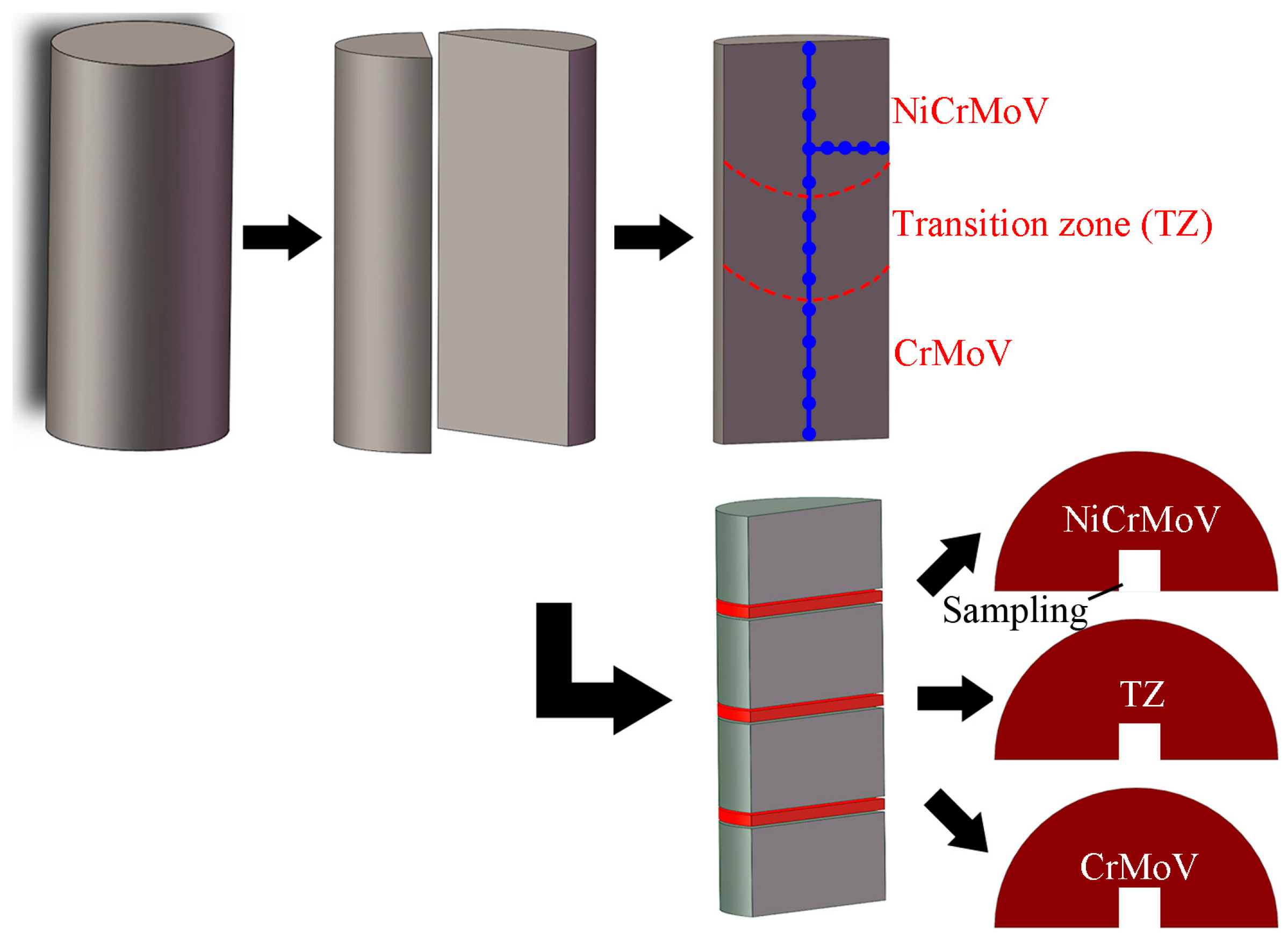
After the ESR process, three dual alloy ingots were obtained and the weight of each ingot was 35.5 kg. Each ingot was evenly divided into two halves along the length direction by wire-electrode cutting. Steel filings were obtained along the longitudinal centerline of the section every 20 mm by drilling, and along the transverse radius every 15 mm for Cr and C analysis, as shown in Figure 1. The Cr mass fraction of each ingot was measured by ICP-AES, and the C mass fraction was analyzed by the carbon and sulfur analyzer. Three slices were taken from the upper (NiCrMoV), middle (TZ), and the lower parts (CrMoV) of each ingot, and three 6 mm × 6 mm × 6 mm specimens were then sampled from three slices, respectively (Figure 1). The NiCrMoV zone, the TZ (transition zone), and the CrMoV zone were distinguished according to the composition profile along the ingot axial. Another part of the ingot was prepared for macrostructure observation, which was ground, polished, and finally etched via the aqua regia for a certain time. Figure 2 demonstrates the macrostructure of three dual alloy ingots. The nine specimens sampled from three ingots for metallographic observation were etched at 75 °C in a picric acid solution, then assessed by optical microscopy (OM, Carl Zeiss, Jena, Germany)
3. Results and Discussion
3.1. Macro- and Microstructure Characterization of Three Ingots Made via ESR with Different Currents
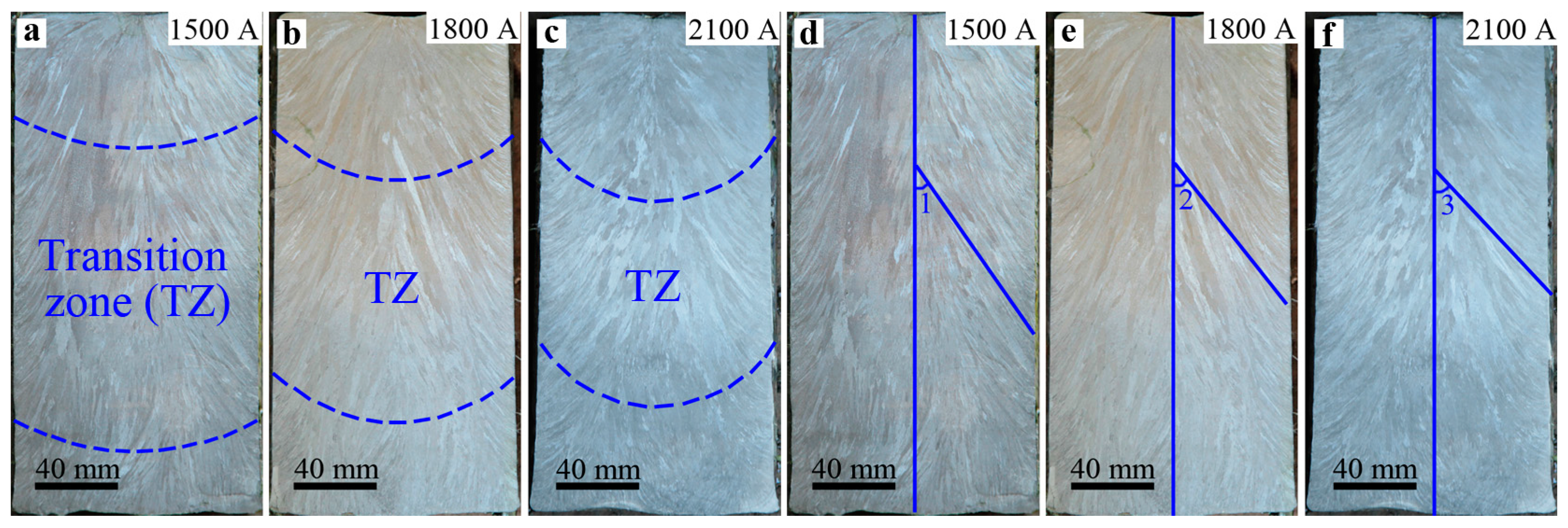
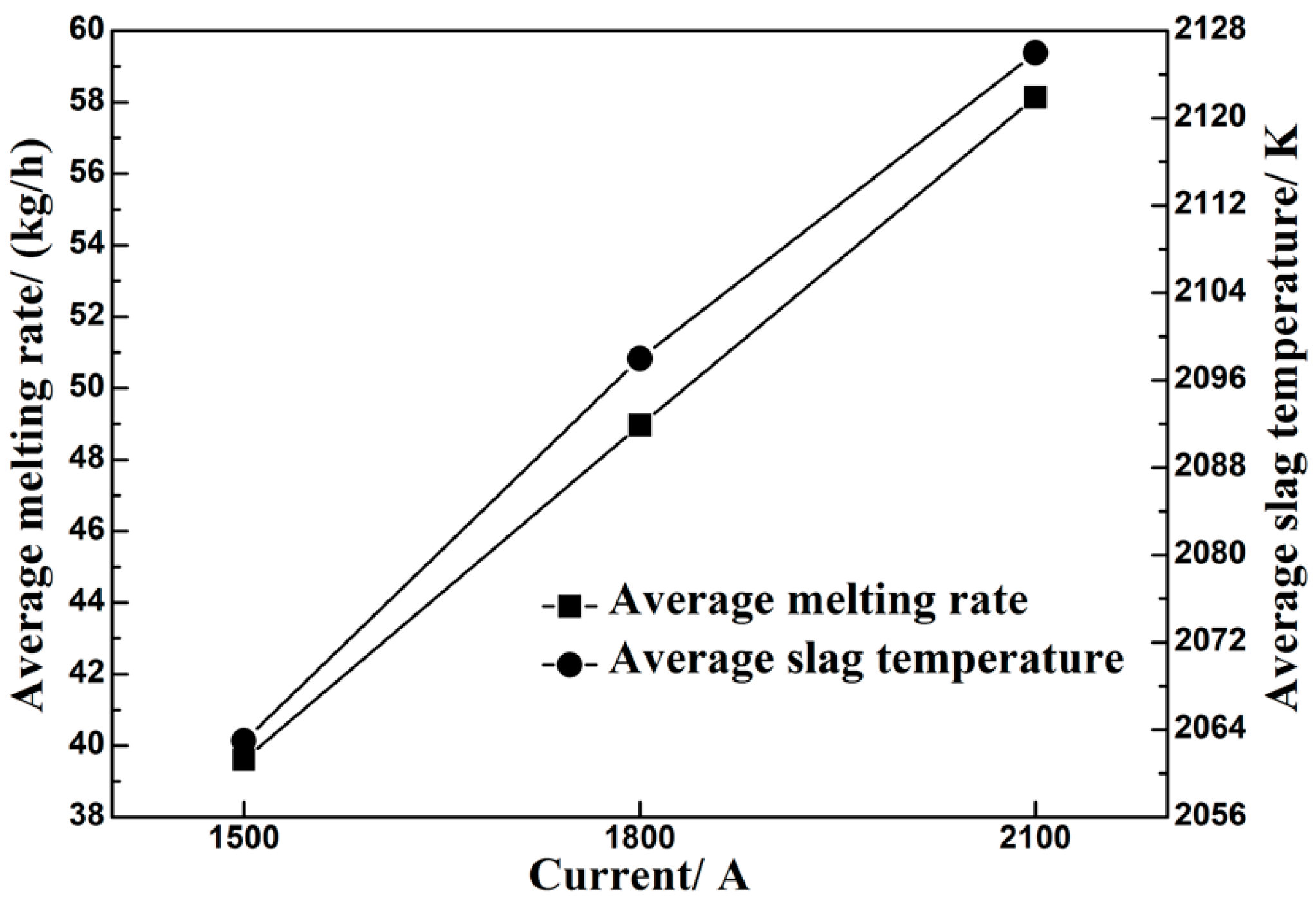
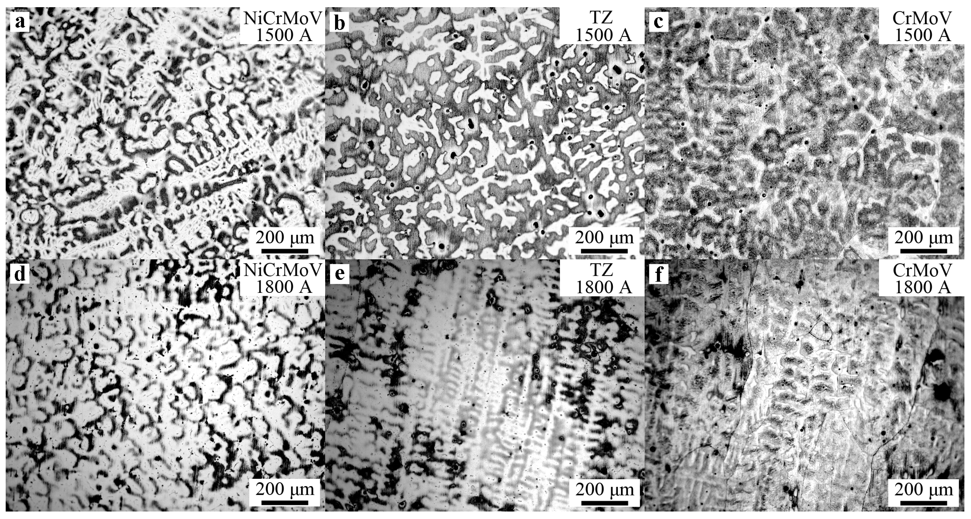
Figure 2 shows the macrostructures of three ingots processes by electroslag remelting with different currents. The zone between two dotted lines in Figure 2a–c is the transition zone (TZ). The typical columnar structure indicates that no discontinuity among the NiCrMoV zone, the CrMoV zone, and the transition zone in three ingots occurs (Figure 2a–c). The macrostructures of three ingots are nearly similar—a thin equiaxed grains region is located under the ingot surface, and the columnar grains region exists inside the ingot, composing the dominant part of ingot. At the beginning of the ESR process, the heat loss to the base plate is dominant. Columnar crystals nucleate at the bottom of the ingot and grow up vertically (Figure 2d–f). With the solidification front advancing, the solidified part acts as a heat choke, and the heat loss to the mold wall increases and cooling intensity decreases gradually due to less heat transferring to the base plate. As a result, the inclined columnar crystals nucleate in the vicinity of the lateral wall and grow to hinder the vertical crystals (Figure 2d–f). The inclined columnar crystals form an inverted chevron structure with a certain angle. The grain growth angle of inclined columnar crystals in three ingots with different currents of 1500 A, 1800 A and 2100 A is 35.1°, 38.6° and 43.7°, respectively (from Angle 1 to Angle 2 and Angle 3 in Figure 2d–f). It is well known that the grain growth direction is perpendicular to the solidification front of the molten metal pool. Figure 3 shows the average melting rate (kg/h) and average slag temperature with different currents, indicating that the melting rate and slag temperature increase with the increase of the current. In general, with the current increasing, the melting rate increases and the molten metal pool becomes deeper due to more Joule heat produced by the larger current passing through the liquid slag [1,5]. A deeper molten metal pool results in a larger grain growth angle in the test with a larger current.
The variation in optical microstructures of three ingots processed by electroslag remelting with different currents is shown in Figure 4. The dendritic structure is formed throughout the cross section, which gradually becomes coarsened from the CrMoV zone to TZ and NiCrMoV zone along the direction from bottom to the top of each ingot because the cooling intensity decreases gradually from the bottom to top of the ingot. When the current increases from 1500 A to 1800 A and 2100 A, the dendritic structure firstly becomes fine, then coarsened. In order to quantitatively analyze the difference of dendritic structure, the average secondary dendrite arm-spacing (SDAS) at NiCrMoV zone and TZ of ingots was measured, as shown in Figure 5. The average SDAS is the average of four SDAS’s at three different points. It should be noted that the SDAS of CrMoV zone was not measured because the crystal structure in CrMoV zone is mainly equiaxed crystal. It can be seen from Figure 5 that SDAS of NiCrMoV zone varies from 61.5 μm to 49.6 μm and 65.3 μm with the current increasing from 1500 A to 1800 A and 2100 A, which varies from 49.2 μm to 40.3 μm and 49.7 μm in TZ.
The SDAS are dominated by the local solidification time (LST/min). LST represents the time that an alloy stays in the solid-liquid two-phase zone (mushy zone). With the increase of LST, the SDAS increases. The LST can be calculated using following equation [5,24]:
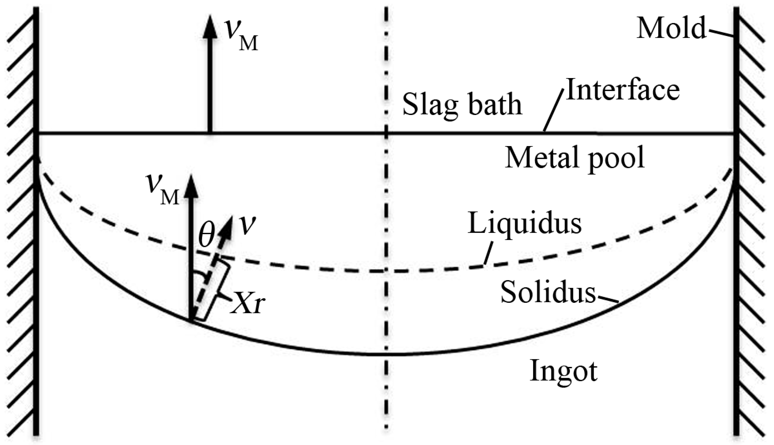
It can be inferred from Equation (1) that LST is dominated by the combined effect of Xr (the width of mushy zone/mm) and v (the local solidification rate/mm/min). As shown in Figure 6, the local solidification rate (v) is perpendicular to the tangent of the solidus curve and has an Angle θ (grain growth angle) to the axis of the ingot. The remelting rate (vM/mm/min) is parallel to the axis, which represents rising velocity of solidus. The local solidification rate (v) can be calculated using the remelting rate (vM) as this geometric relation [24]:
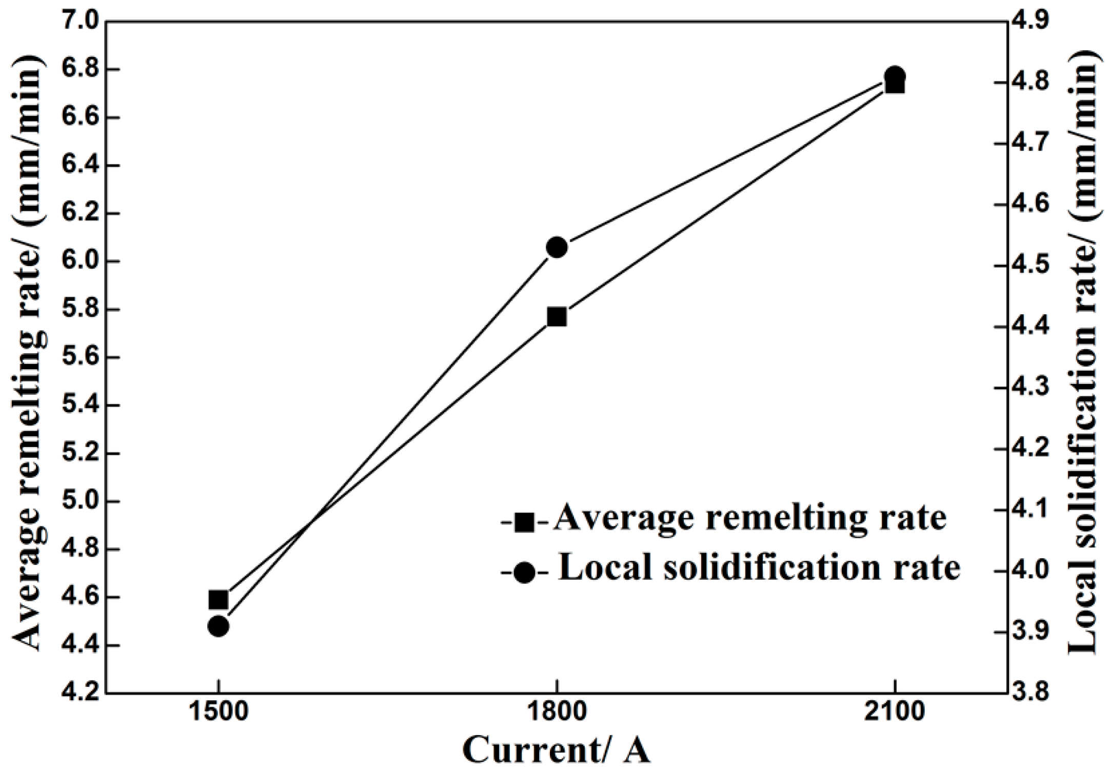
The average remelting rate (vM) can be obtained by the remelting time recorded by the stopwatch. The local solidification rate calculated by Equation (2) and average remelting rate are shown in Figure 7. It indicates that the remelting rate increases evenly with the increase of current. However, correspondingly, the magnitude of increase in local solidification rate (v) decreases due to the increase of the grain growth angle (Angle θ). With the increase of the current, the temperature gradient at the solidification front decreases and the width of the mushy zone increases (Xr) [5]. v increases more rapidly than Xr while the current increases from 1500 A to 1800 A, resulting in the lower LST and smaller SDAS. When the current increases from 1800 A to 2100 A, the magnitude of the increase in v is smaller than that in Xr. As a result, the LST and SDAS increase. It has been confirmed that with the SDAS decreasing, the less dendrite segregation occurs and the precipitates becomes finer [5,8,12]. The SDAS is the smallest in the ingot with 1800 A (Figure 5), implying that less dendrite segregation and finer precipitates exist in the ingot with a current of 1800 A.
The cooling rate at the solidification front (CR/°C/s) can be calculated by Equation (3) as follows [25]:
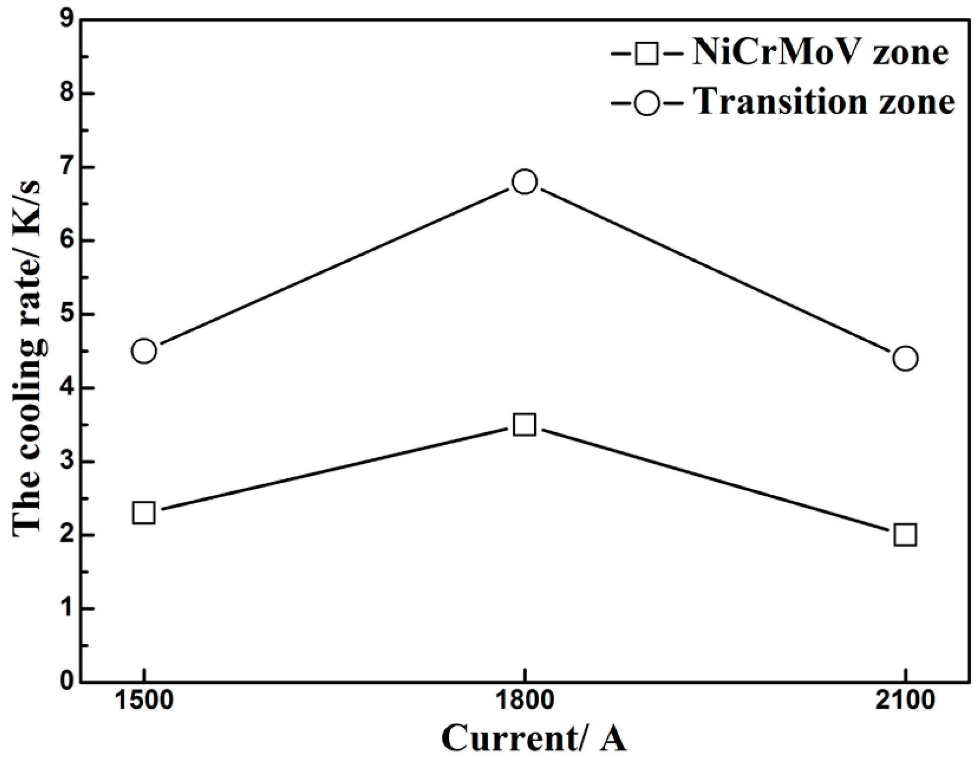
where λS is the SDAS (μm) and [%C] is the carbon mass fraction, which is presented in Table 2. According to Equation (3), the cooling rate of NiCrMoV zone and TZ was calculated, as shown in Figure 8. The cooling rate first increases, then decreases with the current increasing from 1500 A to 1800 A and 2100 A (Figure 8). The cooling rate is closely related to the flows of the molten metal pool, which will be discussed in detail in Section 3.2.
3.2. Macrosegregation of Three Ingots Made via ESR with Different Currents
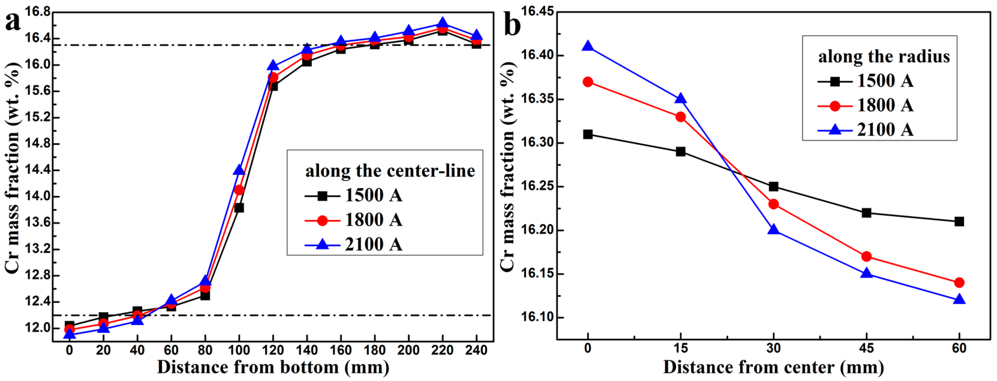
Figure 9 shows the Cr concentration distributions along the longitudinal centerline and the transverse radius in ingots processed by electroslag remelting with different currents. The Cr content increases markedly from the nominal concentration of the CrMoV alloy to that of the NiCrMoV alloy in the TZ of the ingot (Figure 9a). It can be seen from Figure 9a that Cr content along the longitudinal centerline with a current of 1500 A is the first one passing the nominal concentration of the CrMoV alloy, while is the last one exceeding the average concentration of the NiCrMoV alloy. The width of this zone with a composition fluctuation is namely the thickness of the TZ. The thickness of the TZ is about 147 mm, 115 mm and 102 mm with the current increasing from 1500 A to 1800 A and 2100 A, respectively. With the current increasing, the remelting rate (Figure 7) increases [1,25], implying a faster rising velocity of solidus. The TZ of the electrode can be melted, and then solidified into the ingot in shorter time and distance. As a result, the thickness of the TZ decreases with the increase of the current.
Along the transverse radius, the Cr content is higher at the center of all ingots than the edge (Figure 9b). In addition, the concentration gradient between the center and the edge increases with the increase of the current, implying that the severer macrosegregation occurs. It is well known that the macrosegregation is dominated by the solute transport. The flows in the electroslag remelting process have a significant influence on the solute transport [1,19].
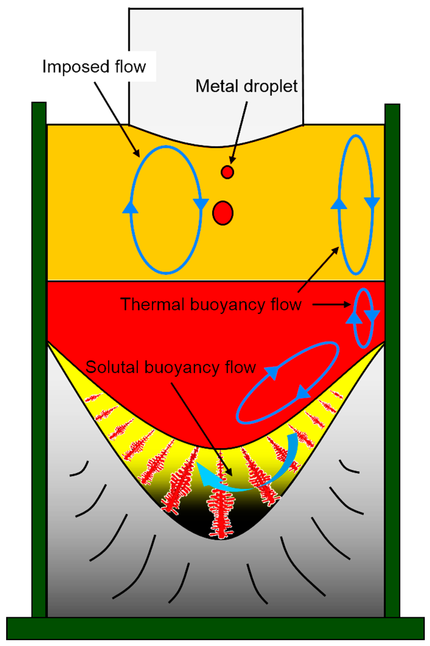
Figure 10 shows the illustration of the flows of the slag bath and metal pool in the ESR process. The metal at the tip of the electrode is remelted by the Joule heating created by the interaction between current and slag to form the metal droplets, which sink through the molten slag to form a crescent shaped molten metal pool that is deep in the center of the ingot and gradually becomes shallow outward in the direction of the radius. It should be noted that the effect of the droplets on the flows in the metal pool was not considered because the momentum carried by small droplets during the small scale ESR process is small. Thermal buoyancy force and Lorentz force are the main driving forces for the flows in the metal pool [26,27]. The molten metal close to the mold wall is cooled by the mold. The hot metal floats up and the cool metal sinks down, and a clockwise circulation is formed near the mold wall. At the solidification front, there is also a large temperature gradient. The cool metal with a higher density will move down along the oblique solidification front and wash out the solidifying mushy zone. The cooling intensity weakens around the base of the molten metal pool. The hot metal rises toward the slag-metal interface and then returns to the mold wall, which also forms a clockwise circular flow at the inclined solidification front. In addition, according to the Faraday’s law of electromagnetic induction, a clockwise circular magnetic field (looking down from the top) would be induced by the downward current. The interaction between the clockwise circular magnetic field and the downward current creates an inward Lorentz force, which also pushes the metal from the edge to the middle.
The solute element Cr becomes enriched in the mushy zone due to the partition ratio (kCr = 0.76) [28]. Furthermore, the density of Cr (ρCr = 6900 kg/m3) is lower than that of iron (ρFe = 7500 kg/m3) [29]. The Cr would be enriched in the molten metal pool due to the buoyancy force, resulting in the so-called gravity segregation. At the solidification front, the solute-poor metal displaces the solute-rich metal through washing out the mushy region due to the clockwise circular flow. Inward Lorentz force also pushes the metal from the edge to the bottom center of metal pool. As a result, the Cr accumulates at the bottom center of the pool and the concentration decreases from the middle to the edge.
With the increase of the current, the slag bath temperature becomes higher (Figure 3) and the flows become faster. The reinforced heat transfer increases the melting rate of the electrode (Figure 3). The metal droplets formed at the tip of the electrode become bigger, which brings more heat to the molten metal pool. The flows in the metal pool also become more intense. Furthermore, the inward Lorentz force also increases with the increase of the current. So, the macrosegregation becomes severer with the increase of the current (Figure 9b).
As mentioned above, the cooling rate at the solidification front first increases, then decreases with the current increasing from 1500 A to 1800 A and 2100 A (Figure 8). The cooling rate is dominated by the flows between the mushy region and metal pool and the temperature gradient at mushy zone of the solidification front (Figure 10). With the current increasing, the temperature of the metal pool increases and the Lorentz force enhances the flows more fiercely, whereas, the temperature gradient at the solidification front decreases (the width of mushy zone Xr increases) [5]. The enhanced flows accelerate the heat transfer, but the reduced temperature gradient weakens the heat transfer at the solidification front. With the current increasing from 1500 A to 1800 A, the enhanced flows play a dominant role in heat transfer and the cooling rate increases at the solidification front. When the current increases form 1800 A to 2100 A, the heat transfer fades due to the decreasing temperature gradient at the mushy zone of the solidification front and the cooling rate decreases.
4. Conclusions
Three heats with different currents were designed to investigate the effect of the current on structure and macrosegregation in dual alloy ingot processed by electroslag remelting, the following conclusions can be reached.
- (1)
- The macrostructures of three ingots are nearly similar. The thin equiaxed grains region is situated under the ingot surface, and the columnar grains region lies inside the ingot. The typical columnar structure shows no discontinuity among the CrMoV zone, the transition zone and NiCrMoV zone in three ingots. With the increase of the current, the grain growth angle (the angle between grain growth direction and axis of ingot) increases due to the deeper molten metal pool.
- (2)
- The SDAS firstly decreases, then increases with the increase of the current. The SDAS is dominated by the combined effect of the local solidification rate and thickness of the mushy region. With a current of 1800 A, the SDAS is the smallest and the cooling rate is the fastest, indicating that less dendrite segregation and finer precipitates exist in the ingot.
- (3)
- With the increase of the current, the thickness of the transition zone decreases. The macrosegregation becomes severer due to the fiercer flows forced by the Lorentz force and the thermal buoyancy force. The cooling rate first increases, then decreases, which is dominated by a combined effect of the flows between the mushy region and metal pool and the temperature gradient at the mushy zone of the solidification front.
- (4)
- Under the comprehensive consideration, the dual alloy ingot processed by the ESR with a current of 1800 A is the best due to the smallest SDAS, the appropriate grain growth angle, moderate macrosegregation and thickness of the transition zone. The present work clarifies the effect of the current on the structure and macrosegregation in the dual alloy ingot processed by the ESR, providing a reference for the parameter election of the manufacture of the dual alloy rotor to be used in steam turbines using a combined cycle.
Acknowledgments
The authors gratefully acknowledge the support from the National Natural Science Foundation of China (Grant No. 51210007) and the Key Program of Joint Funds of the National Natural Science Foundation of China and the Government of Liaoning Province (Grant No. U1508214).
Author Contributions
Guangqiang Li and Baokuan Li conceived and designed the experiments; Qiang Wang, Yu Liu, Zhao Zhang and Li Wang performed the experiments; Qiang Wang and Yu Liu analyzed the data; Baokuan Li contributed materials and tools; Yu Liu wrote the paper.
Conflicts of Interest
The authors declare no conflict of interest. The founding sponsors had no role in the design of the study; in the collection, analyses, or interpretation of data; in the writing of the manuscript, and in the decision to publish the results.
Abbreviations
The following abbreviations are used in this manuscript:
| ESR | Electroslag remelting |
| TZ | Transition Zone |
| ICP-AES | Inductively Coupled Plasma-Atomic Emission Spectroscopy |
| OM | Optical Microscopy |
| SDAS | Secondary Dendrite Arm-Spacing |
| LST | Local Solidification Time |
References
- Wang, Q.; Yan, H.; Ren, N.; Li, B. Effect of current on solute transport in electroslag remelting dual alloy ingot. Appl. Therm. Eng. 2016, 101, 546–567. [Google Scholar] [CrossRef]
- Zieliński, A.; Golański, G.; Sroka, M. Comparing the methods in determining residual life on the basis of creep tests of low-alloy Cr-Mo-V cast steels operated beyond the design service life. Int. J. Press. Vessels Pip. 2017, 152, 1–6. [Google Scholar] [CrossRef]
- Sroka, M.; Zieliński, A.; Dziuba-Kałuża, M. Assessment of the Residual Life of Steam Pipeline Material beyond the Computational Working Time. Metals 2017, 7, 82. [Google Scholar] [CrossRef]
- Zieliński, A.; Golański, G.; Sroka, M. Estimation of long-term creep strength in austenitic power plant steels. Mater. Sci. Technol. 2016, 32, 780–785. [Google Scholar] [CrossRef]
- Li, Z.B. Electroslag Metallurgy Theory and Practice; Metallurgical Industry Press: Beijing, China, 2010; pp. 17–18. (In Chinese) [Google Scholar]
- Wang, Q.; Li, B. Numerical investigation on the effect of fill ratio on macrosegregation in electroslag remelting ingot. Appl. Therm. Eng. 2015, 91, 116–125. [Google Scholar] [CrossRef]
- Jiang, Z.H. Physical Chemistry and Transport Phenomena for Electroslag Metallurgy; Northeastern University Press: Shenyang, China, 2000; pp. 143–146. (In Chinese) [Google Scholar]
- Liu, Y.; Zhang, Z.; Li, G.; Wang, Q; Wang, L.; Li, B. The structural evolution and segregation in a dual alloy ingot processed by electroslag remelting. Metals 2016, 6, 325. [Google Scholar] [CrossRef]
- Kajikawa, K.; Ganesh, S.; Kimura, K.; Kudo, H.; Nakamura, T.; Tanaka, Y.; Schwant, R.; Gatazka, F.; Yang, L. Forging for advanced trubine applications: Development of multiple alloy rotor forging for turbine application. Ironmak. Steelmak. 2007, 34, 216–220. [Google Scholar] [CrossRef]
- Rao, L.; Zhao, J.H.; Zhao, Z.X.; Ding, G.; Geng, M.P. Macro-and microstructure evolution of 5CrNiMo steel ingots during electroslag remelting process. J. Iron Steel Res. Int. 2014, 21, 644–652. [Google Scholar]
- Chang, L.Z.; Shi, X.F.; Yang, H.S.; Li, Z.B. Effect of low-frequency AC power supply during electroslag remelting on qualities of alloy steel. J. Iron Steel Res. Int. 2009, 16, 7–11. [Google Scholar] [CrossRef]
- Liu, Z.; Li, J.; Fu, H. Dendritic arm spacing and microsegregation of directionally solidified superalloy DZ22 at various solidification rates. Acta Metall. Sin. 1995, 31, 329–332. (In Chinese) [Google Scholar]
- Li, B.; Wang, Q.; Wang, F.; Chen, M. A coupled cellular automaton-finite-element mathematical model for the multiscale phenomena of electroslag remelting H13 die steel ingot. JOM 2014, 66, 1153–1165. [Google Scholar] [CrossRef]
- Ma, D.; Zhou, J.; Chen, Z.; Zhang, Z.; Chen, Q.; Li, D. Influence of thermal homogenization treatment on structure and impact toughness of H13 ESR steel. J. Iron Steel Res. Int. 2009, 16, 56–60. [Google Scholar] [CrossRef]
- Mitchell, A. Solidification in remelting processes. Mater. Sci. Eng. A 2005, 413, 10–18. [Google Scholar] [CrossRef]
- Hernandez-Morales, B.; Mitchell, A. Review of mathematical models of fluid flow, heat transfer, and mass transfer in electroslag remelting process. Ironmak. Steelmak. 1999, 26, 423–438. [Google Scholar] [CrossRef]
- Mitchell, A.; Joshi, S.; Cameron, J. Electrode temperature gradients in the electroslag process. Metall. Trans. 1971, 2, 561–567. [Google Scholar] [CrossRef]
- Mitchell, A.; Joshi, S. The thermal characteristics of the electroslag process. Metall. Trans. 1973, 4, 631–642. [Google Scholar] [CrossRef]
- Fezi, K.; Yanke, J.; Krane, M.J.M. Macrosegregation during electroslag remelting of alloy 625. Metall. Mater. Trans. B 2015, 46, 766–779. [Google Scholar] [CrossRef]
- Wang, Q.; Wang, F.; Li, B.; Tsukihashi, F. A three-dimensional comprehensive model for prediction of macrosegregation in electroslag remelting ingot. ISIJ Int. 2015, 55, 1010–1016. [Google Scholar] [CrossRef]
- Jardy, A.; Ablitzer, D.; Wadier, J.F. Magnetohydronamic and thermal behavior of electroslag remelting slags. Metall. Mater. Trans. B 1991, 22, 111–120. [Google Scholar] [CrossRef]
- Kharicha, A.; Ludwig, A.; Wu, M. On melting of electrodes during electro-slag remelting. ISIJ Int. 2014, 54, 1621–1628. [Google Scholar] [CrossRef]
- Medina, S.F.; Andres, M.P. Electrical Field in the Resistivity Medium (Slag) of the ESR Process: Influence on Ingot Production and Quality. Ironmak. Steelmak. 1987, 14, 110–121. [Google Scholar]
- Zhong, Y.; Qiang, L.; Fang, Y.; Wang, H.; Peng, M.; Dong, L.; Zheng, T.; Lei, Z.; Ren, W.; Ren, Z. Effect of transverse static magnetic field on microstructure and properties of GCr15 bearing steel in electroslag continuous casting process. Mater. Sci. Eng. A 2016, 660, 118–126. [Google Scholar] [CrossRef]
- Won, Y.M.; Thomas, B.G. Simple model of microsegregation during solidification of steels. Metall. Mater. Trans. A 2001, 32, 1755–1767. [Google Scholar] [CrossRef]
- Dong, J.; Cui, J.; Zeng, X.; Ding, W. Effect of low-frequency electromagnetic field on microstructures and macrosegregation of Φ270 mm DC ingots of an Al-Zn-Mg-Cu-Zr alloy. Mater. Lett. 2005, 59, 1502–1506. [Google Scholar] [CrossRef]
- Zhang, B.; Cui, J.; Lu, G. Effect of low-frequency magnetic field on macrosegregation of continuous casting aluminum alloys. Mater. Lett. 2003, 57, 1707–1711. [Google Scholar] [CrossRef]
- Schneider, M.C.; Beckermann, C. Formation of macrosegregation by multicomponent thermosolutal convection during the solidification of steel. Metall. Mater. Trans. A 1995, 26, 2373–2388. [Google Scholar] [CrossRef]
- Weber, V.; Jardy, A.; Dussoubs, B.; Ablitzer, D.; Ryberon, S.; Schmitt, V.; Hans, S.; Poisson, H. A comprehensive model of the electroslag remelting process: Description and validation. Metall. Mater. Trans. B 2009, 40, 271–280. [Google Scholar] [CrossRef]
Figure 1.
Schematic drawing of the dissection of the ESR dual alloy ingot.

Figure 2.
The macrostructures of the ingots processed by electroslag remelting with different currents of (a,d) 1500 A, (b,e) 1800 A and (c,f) 2100 A. The zone between two dotted lines in (a–c) is the transition zone.
Figure 2.
The macrostructures of the ingots processed by electroslag remelting with different currents of (a,d) 1500 A, (b,e) 1800 A and (c,f) 2100 A. The zone between two dotted lines in (a–c) is the transition zone.

Figure 3.
Average melting rate and average slag temperature with different currents.

Figure 4.
Optical micrographs of the (a,d,g) NiCrMoV zone, (b,e,h) TZ and (c,f,i) CrMoV zone in the ingots processed by electroslag remelting with different currents of (a–c) 1500 A, (d–f) 1800 A and (g–i) 2100 A.
Figure 4.
Optical micrographs of the (a,d,g) NiCrMoV zone, (b,e,h) TZ and (c,f,i) CrMoV zone in the ingots processed by electroslag remelting with different currents of (a–c) 1500 A, (d–f) 1800 A and (g–i) 2100 A.

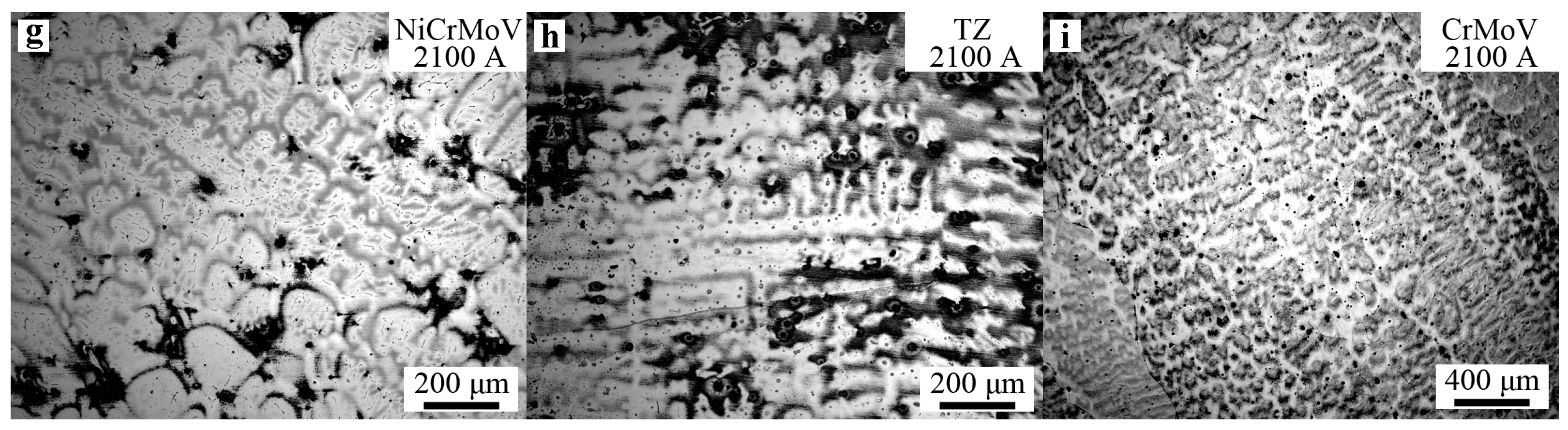
Figure 5.
Secondary dendritic arm spacing at different positions (NiCrMoV zone and transition zone) of the ingots processed by electroslag remelting with different currents.
Figure 5.
Secondary dendritic arm spacing at different positions (NiCrMoV zone and transition zone) of the ingots processed by electroslag remelting with different currents.
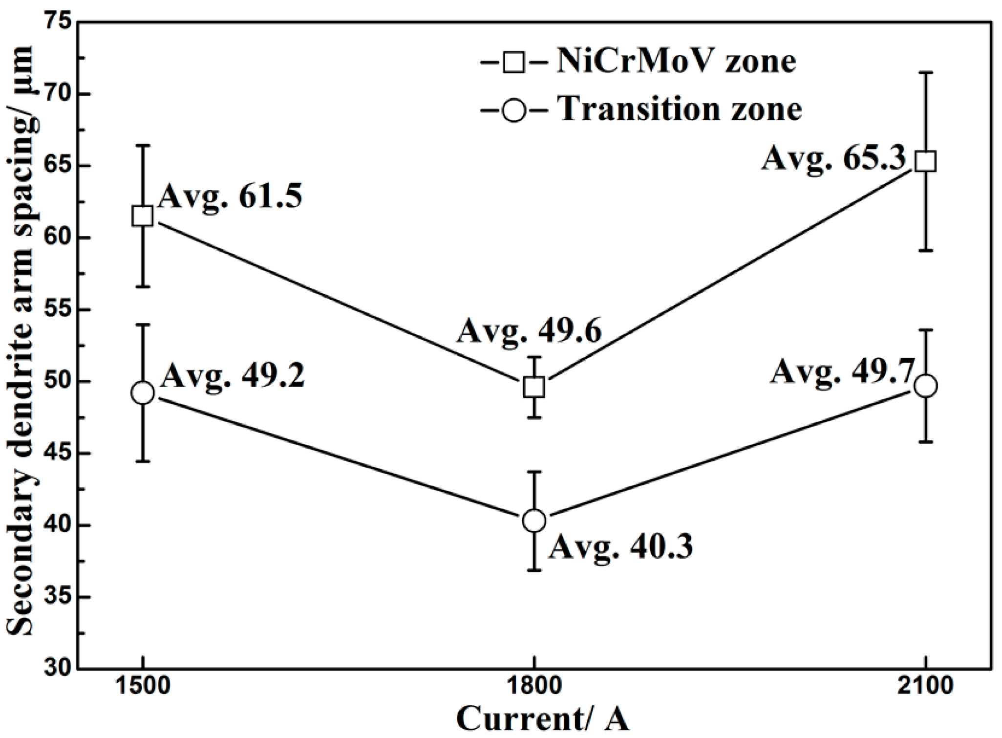
Figure 6.
Schematic of solidification interface and the relationship between remelting rate and cooling rate.
Figure 6.
Schematic of solidification interface and the relationship between remelting rate and cooling rate.

Figure 7.
Average remelting rate and local solidification rate with different currents.

Figure 8.
The cooling rates at different positions (NiCrMoV zone and transition zone) of the ingots processed by electroslag remelting with different currents.
Figure 8.
The cooling rates at different positions (NiCrMoV zone and transition zone) of the ingots processed by electroslag remelting with different currents.

Figure 9.
Cr concentration distributions along (a) the longitudinal centerline and (b) the transverse radius in ingots processed by electroslag remelting with different currents.
Figure 9.
Cr concentration distributions along (a) the longitudinal centerline and (b) the transverse radius in ingots processed by electroslag remelting with different currents.

Figure 10.
Illustration of the flows of the slag bath and metal pool in the ESR process.


Table 1.
Chemical composition of consumable electrode used in present experiment (wt. %).
| Electrode | C | Mn | Si | P | S | Cr | Ni | Mo | Nb | Al | Ti | T.[O] |
|---|---|---|---|---|---|---|---|---|---|---|---|---|
| Elec. NiCrMoV | 0.106 | 1.67 | 0.37 | 0.018 | 0.039 | 16.28 | 7.45 | 0.117 | 0.039 | 0.009 | 0.012 | 0.0156 |
| Elec. CrMoV | 0.074 | 3.94 | 0.40 | 0.020 | 0.011 | 12.25 | 5.85 | 0.140 | 0.032 | 0.014 | 0.008 | 0.0121 |
Table 2.
Carbon mass fraction of NiCrMoV zone and transition zone (TZ) in the ingots processed by the ESR with different currents (wt. %).
Table 2.
Carbon mass fraction of NiCrMoV zone and transition zone (TZ) in the ingots processed by the ESR with different currents (wt. %).
| ESR Ingots | [%C] | ||
|---|---|---|---|
| 1500 A | 1800 A | 2100 A | |
| NiCrMoV | 0.108 | 0.103 | 0.107 |
| TZ | 0.091 | 0.093 | 0.094 |
© 2017 by the authors. Licensee MDPI, Basel, Switzerland. This article is an open access article distributed under the terms and conditions of the Creative Commons Attribution (CC BY) license (http://creativecommons.org/licenses/by/4.0/).
Share and Cite
MDPI and ACS Style
Liu, Y.; Zhang, Z.; Li, G.; Wang, Q.; Wang, L.; Li, B. Effect of Current on Structure and Macrosegregation in Dual Alloy Ingot Processed by Electroslag Remelting. Metals 2017, 7, 185. https://doi.org/10.3390/met7060185
AMA Style
Liu Y, Zhang Z, Li G, Wang Q, Wang L, Li B. Effect of Current on Structure and Macrosegregation in Dual Alloy Ingot Processed by Electroslag Remelting. Metals. 2017; 7(6):185. https://doi.org/10.3390/met7060185
Chicago/Turabian StyleLiu, Yu, Zhao Zhang, Guangqiang Li, Qiang Wang, Li Wang, and Baokuan Li. 2017. "Effect of Current on Structure and Macrosegregation in Dual Alloy Ingot Processed by Electroslag Remelting" Metals 7, no. 6: 185. https://doi.org/10.3390/met7060185
Note that from the first issue of 2016, this journal uses article numbers instead of page numbers. See further details here.