1. Introduction
Friction stir welding (FSW) is a solid state joining technology in which friction and plastic dissipation are sources of heat generation and material softening.
The tool pin profile has a remarkable effect on the friction between the tool and the workpiece and the foremost effect on the plastic deformation of the surrounding material. FSW pin tools are often featured with thread forms as they are beneficial for improving the tool performance and contribute to an effective material transportation near the weld and the generation of a defect free stir zone [
1].
Pin tools with threaded features are often used to investigate the relationship between the tool and the microstructural properties obtained using different welding conditions.
In [
2], thread pins are used for friction stir welding of two aluminium alloys: AA7050-T7451 and AA6061-T651. They investigate the effect of the thread on the process in terms of in-plane reactions on the pin tool, torque, temperature and the quality of welds.
In [
1], heat treatable AA6061 and non-heat treatable AA5086 aluminum alloys are welded by using three different pin tools. It is found that FSW using threaded cylindrical pins provides better material flow between two alloys among others.
In [
3], the influence of the tool geometries upon the axial and translational forces, temperature and mechanical properties for AA7075-T6 is studied. In their experimental work, threaded tapered, non-threaded triangular and non-threaded cylindrical pins are considered.
In [
4], the effect of tool geometry on friction stir welding of polyethylene-polypropylene is investigated. Threaded cylindrical, squared, triangular and straight cylindrical pin shapes are considered. Interaction effects of welding variables, including rotational speed and traverse speed are studied.
In [
5], a half-threaded pin tool to enhance the material flow at the lap interface is manufactured. The effect of manufactured pin on the process is compared with that of full-threaded pin in terms of temperature, bonding and material flow. It is observed, for instance, that the peak temperature during the process using the half-threaded pin is lower than that using the full-threaded pin.
In [
6], Colegrove et al. use the computational fluid dynamics (CFD) code, FLUENT, to model the 3D metal flow in FSW using a threaded pin. It is found that the model generates an excessive amount of heat, leading to over-prediction of the weld temperature.
Atharifar et al. [
7] analyze the viscous and inertia loads applied to the FSW tool by varying the welding parameters using FLUENT. A right-handed one-way thread pin tool with a concaved, smooth shoulder is considered to simulate the material flow and heat transfer in the FSW of AA6061.
Even though numerous studies, mainly experimental, of the effect of pin threads on the weld have been carried out, there is an urgent need for a fast and accurate numerical model for the analysis of the FSW process. This model should contain a suitable friction model to properly describe the tribological condition at the tool/workpiece interface, capable of considering real process behavior such as the effect of non-uniform pressure distribution under the tool.
A 3D finite element analysis is able to deal with several process complexities such as a concave shoulder, tool tilt and threaded pin profiles. However, the large computational cost makes it inconceivable as a routinely used design tool [
8]. In previous works of the authors, a robust and fast numerical model was developed to study FSW under different welding conditions [
9,
10,
11,
12,
13,
14,
15]. A fully coupled thermo-mechanical model together with an enhanced friction law was addressed to provide a more realistic thermo-mechanical response in comparison with the existing models. The model took the benefits of an apropos kinematic framework combing Arbitrary Lagrangian Eulerian (ALE), Eulerian and Lagrangian formulations for the stir zone, the workpiece and the pin-tool, respectively. A two-stage speed-up strategy was incorporated to reduce the simulation time while preserving the accuracy of the results.
In the present work, the model previously developed by the authors is adopted for the simulation of a FSW process with a cylindrical threaded pin tool. The use of an apropos kinematic framework permits dealing with arbitrary pin shapes as the threaded pin tool, without the necessity of using a re-meshing procedure due to the large deformation of the material around the threaded pin tool. Moreover, it facilitates the application of the boundary conditions. The enrichment of the model with an enhanced friction law permits to accurately predict not only the temperature field but also the torque and forces exerted by the tool in all the directions. This is mostly lacking in previous works in the FSW field. The use of a two-stage speed-up strategy is especially important when simulating industrial cases, as the model is 3D and a large number of elements are used in the discretization of the geometry. It is shown here that the framework, formulation and computational strategy are not only applicable to featureless pins but also to pins with features such as threads. The analyses are calibrated and validated through the experimental measurements performed by the industrial partner (Sapa) for aluminum alloy AA6063-T6. The correlations obtained by means of this comparison not only validate the model but also provide insight regarding the effects of the threaded pins upon torque, forces and temperature field. Also, the differences between threaded and featureless cylindrical pins of similar dimensions are studied in detail.
The paper is structured as follows: In
Section 2, the overall solution strategy applied for simulation of FSW process using cylindrical threaded pin tool is summarized. In
Section 3, the numerical assessment and the calibration of the model using the experimental data are presented.
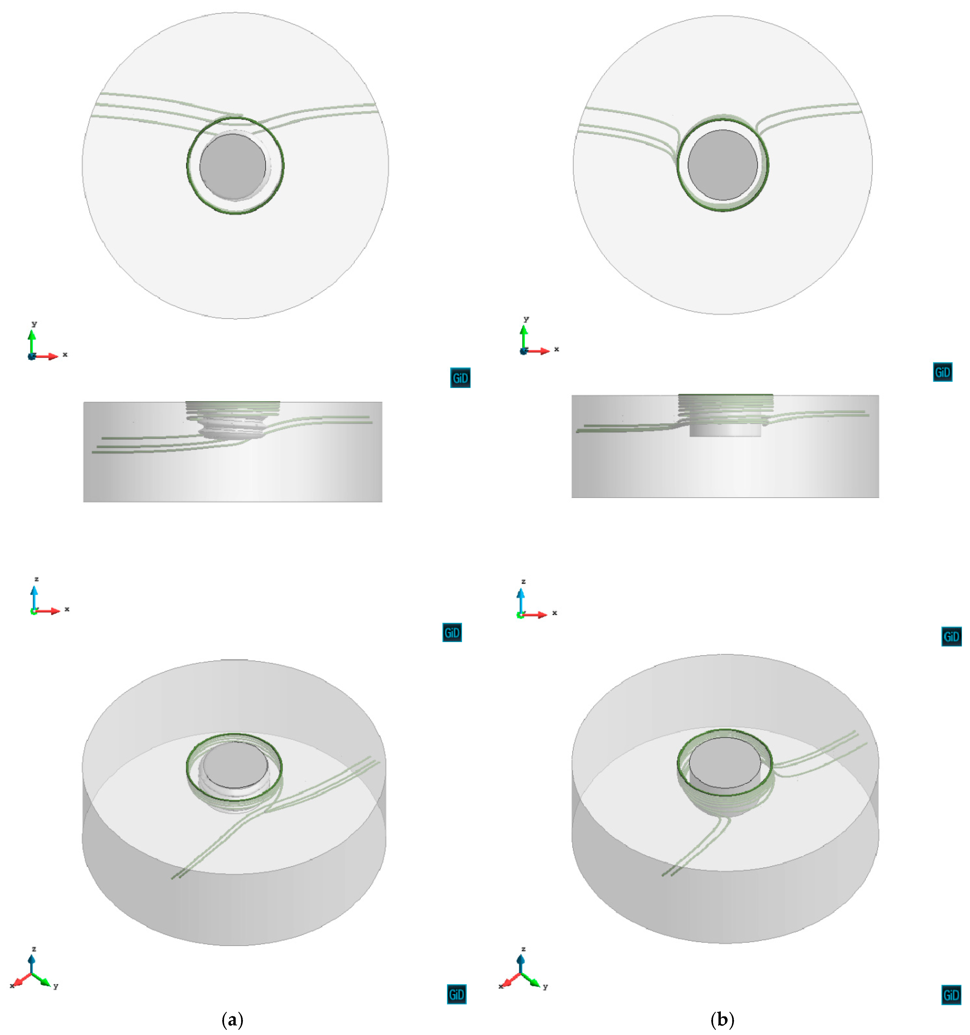
Section 4 is devoted to the comparison of the weld obtained using threaded and featureless cylindrical tool pins.
2. The Solution Strategy
In this work, a local analysis of the FSW process is performed. This means that the domain surrounding the thermo-mechanically affected zone (TMAZ) and the tool are considered in the simulation. The tool rotates rigidly with a constant speed and the plate moves with the advancing velocity opposite to the welding direction.
The governing equations and the boundary conditions used for the definition of the transient coupled thermo-mechanical problem are summarized in
Table 1. The nomenclature for the variables and properties involved is listed in
Table 2. Additional details on the formulation can be found in References [
9,
10].
A two-stage simulation strategy is adopted [
14]. A coupled thermo-mechanical problem is solved in both stages [
13,
16].
The first stage consists of a “forced” transient analysis aiming to reach the steady-state quickly. This objective is achieved by increasing the thermal diffusivity in the energy balance equation. An acceleration parameter is used to reduce the inertia term to speed-up this transient stage and reach the steady-state temperature field in a decreased number of time-steps.
The second stage performs a transient analysis in which the temperature and velocity field obtained in the first stage are considered as initial condition.
In the first stage, an Eulerian framework is adopted for the workpiece. Therefore, no periodic stage due to the rotating movement of the tool is assumed. In the second stage, an apropos kinematic framework is adopted taking advantage of combining ALE, Eulerian and Lagrangian formulations [
9,
10]. The Lagrangian framework is used for the rotating pin, the ALE framework is considered at the stir zone of the work-piece (TMAZ), and the Eulerian framework is used in the remaining part of the work-piece. This allows the analysis of non-cylindrical pin shapes presenting the periodic solution due to the rotation of the tool.
The two-stage speed-up strategy performs the entire simulation preserving the capabilities of the original model to predict FSW forces and torque for any types of pin shape in addition to the material flow visualization [
14].
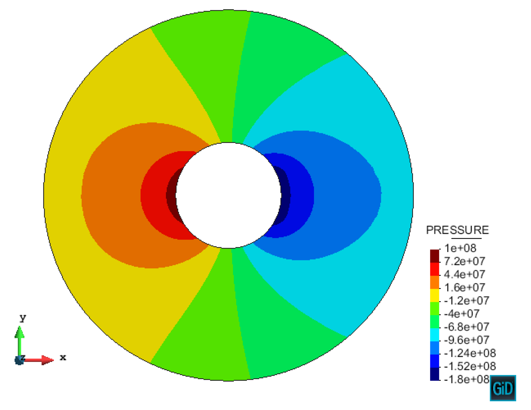
Both plastic dissipation and friction are considered as the sources of heat generation. Friction is modelled by a modified Norton’s friction model developed by authors in [
15]. This model considers the effect of a non-uniform pressure distribution under the tool (see
Figure 1 for a qualitative presentation of pressure distribution around the tool) which results in higher friction in front of the tool and lower friction at the rear of the tool.
The modified Norton’s friction law reads:
where
is the friction shear stress, 0 ≤
q ≤ 1 is the sensitivity parameter and
is the relative sliding velocity between the tool and the workpiece contact surfaces.
is the sliding direction. The non-uniform consistency parameter
is defined by the following expression, to be considered at the tool-workpiece interface, as:
being
x the position of each point located at the tool/workpiece interface, with respect to the rotation axis, projected along the welding direction and
R the shoulder radius. Friction tractions vary from the maximum value at the front side of the shoulder to the minimum value at the rear side. Since the temperature in the working zone does not vary significantly, the maximum (
) and minimum (
) consistency parameters are assumed to be dependent on the average working temperature only.
3. Validation of Numerical Model from Experimental Data
In this section, the numerical simulation of the FSW process is performed for a threaded pin tool. The results obtained using the modified Norton’s friction model are compared with the experimental measurements performed by the industrial partner (Sapa).
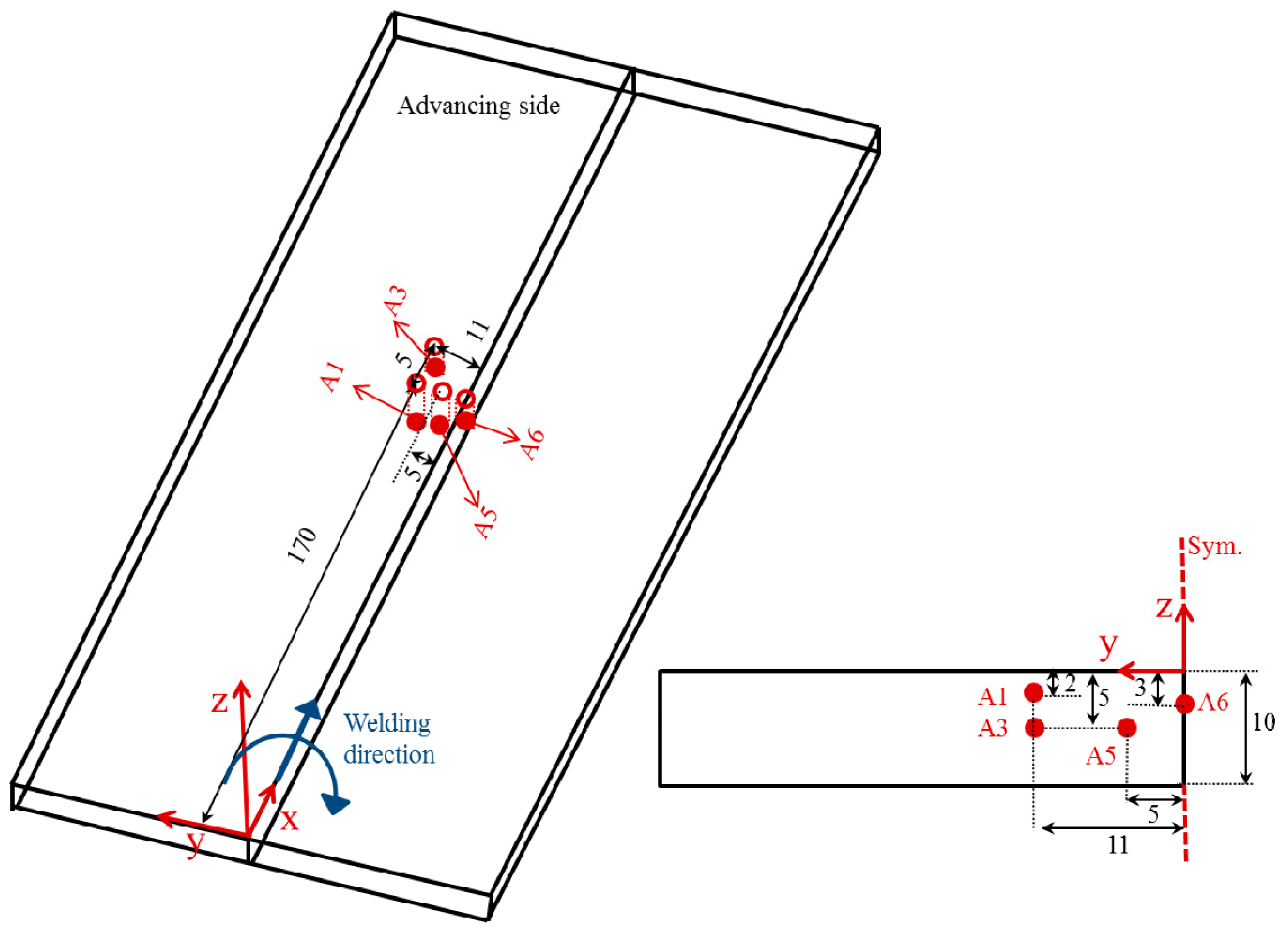
The workpiece geometry is shown in
Figure 2 (300 × 50 × 10 mm
3). The diameter of the tool shoulder is 18 mm. The average diameter and height of the tool pin are 7 mm and 4 mm, respectively.
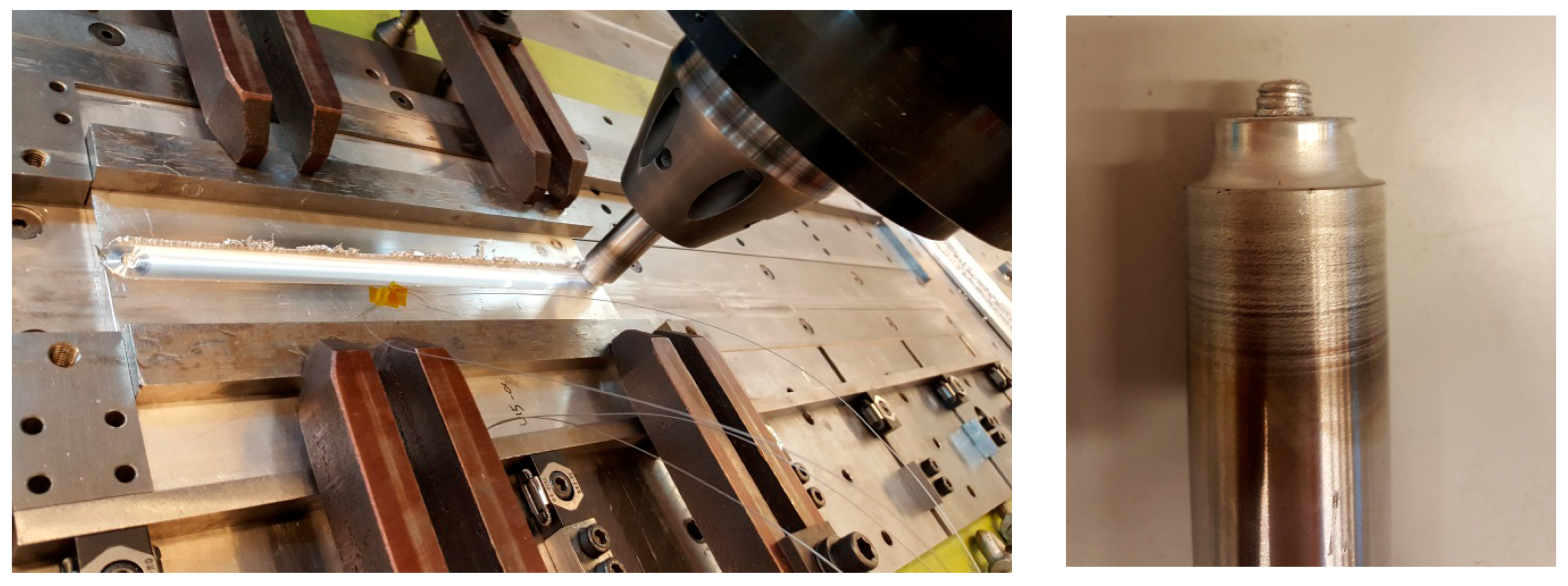
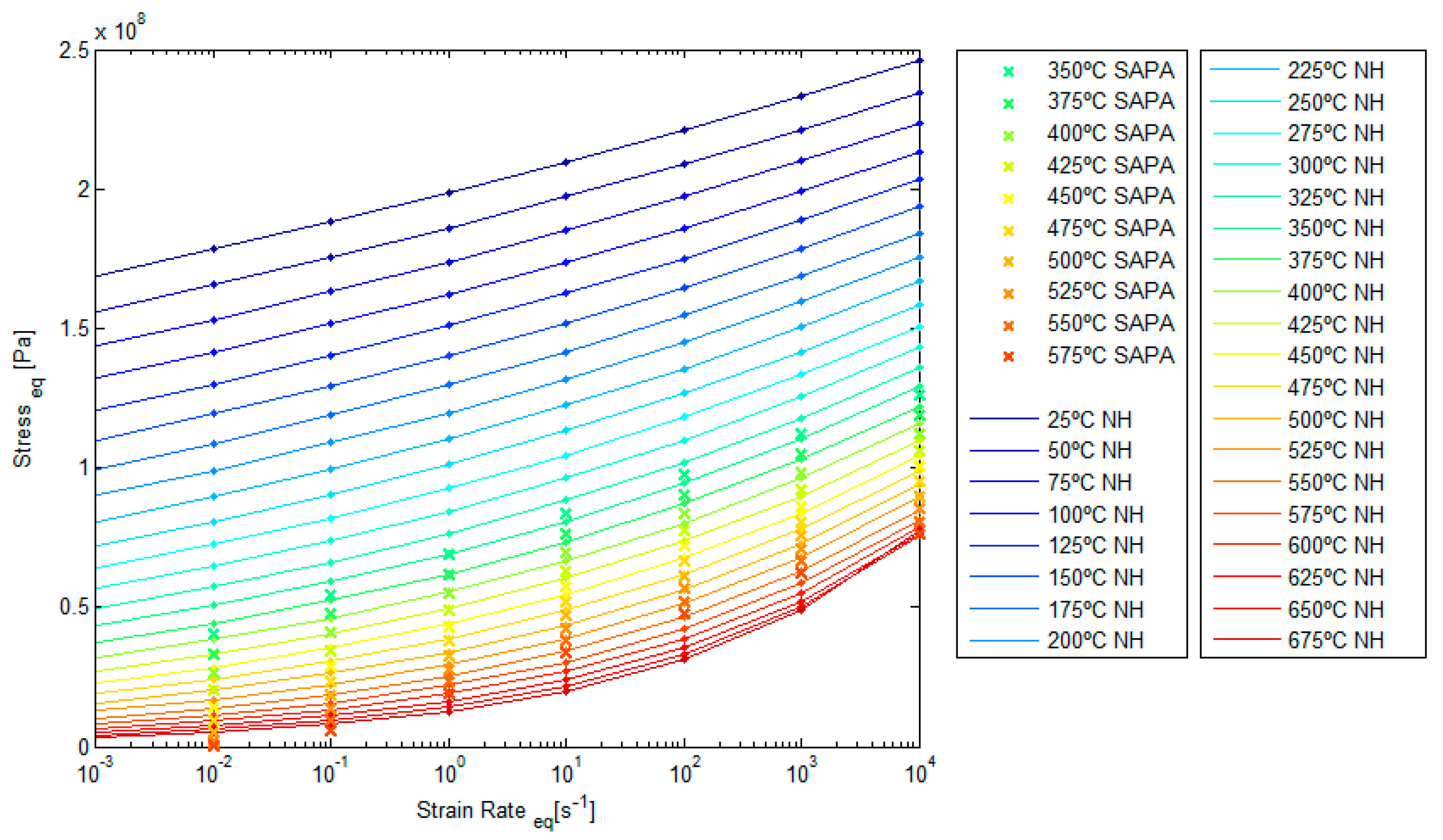
Figure 3 shows the experimental settings including the FSW robot, workpiece, tool, clamping system and thermocouples. The process parameters are: advancing velocity = 400 mm/min and tool rotation speed = 600 rpm. The material used in this test is aluminium alloy (AA6063-T6). The temperature-dependent thermo-mechanical properties are shown in
Figure 4.
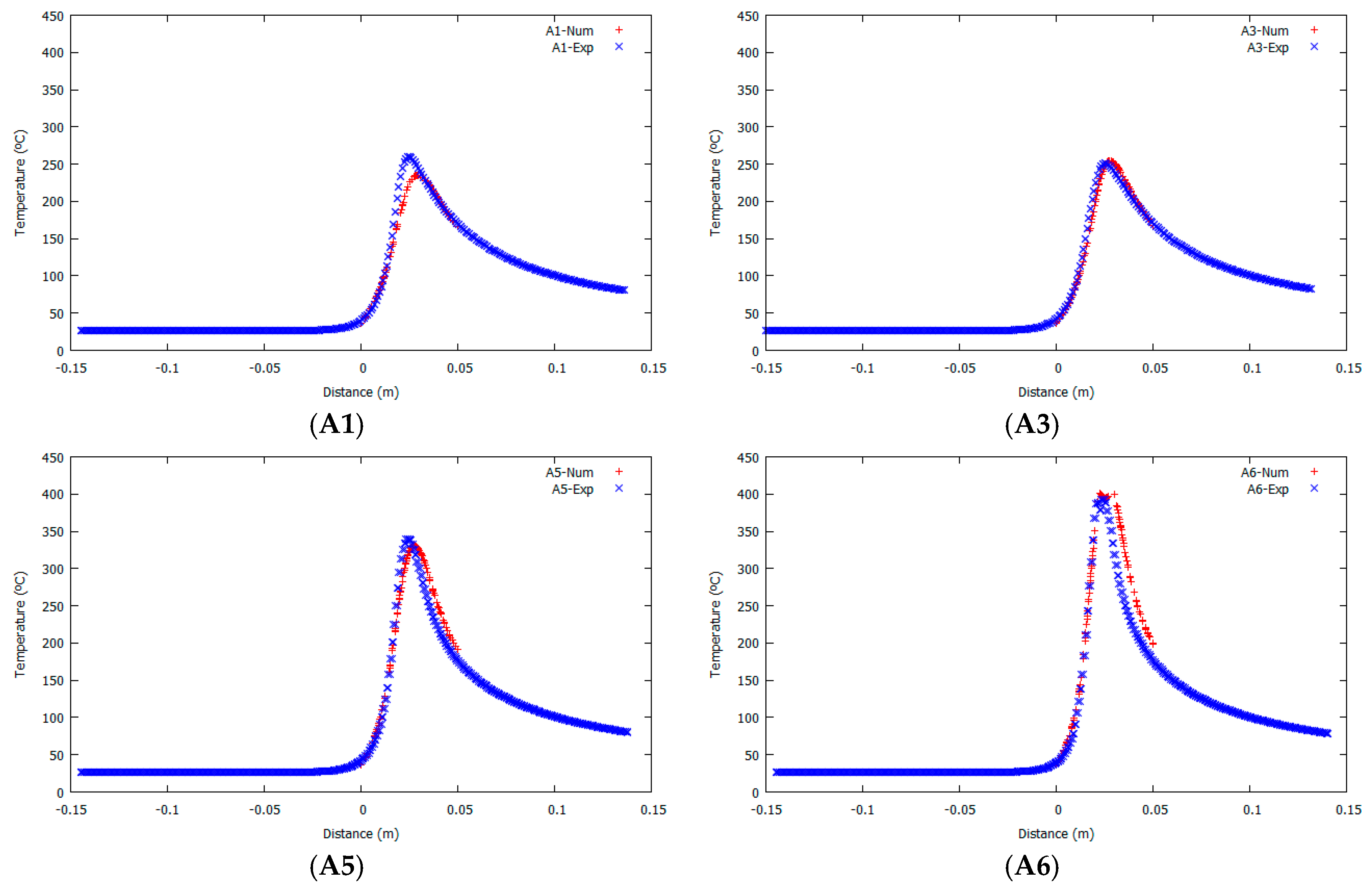
Figure 2 shows the position of the thermocouples in a transversal section of the workpiece with respect to the weld line. Their distance in mm with respect to a reference axis located at top left on the weld line is: A1(170,11,−5), A3(175,11,−2), A5(170,5,−5), A6(170,0,−3).
The simulation considers a domain of 50 × 50 × 10 mm
3. The tool advances in the
x direction of the reference axes. It is assumed that 70% of the plastic dissipation is converted into heat [
17,
18].
Friction parameters amin and amax at the tool/workpiece interfaces (both pin and shoulder) are determined from the calibration of the friction model by matching the numerical results with the experimental data in terms of temperature evolution and process forces.
The analysis adopts amin = 5 × 10⁷ and amax = 109 at tool/workpiece interfaces. A vertical velocity of 2.4 mm/s is applied on the tool in order to obtain the vertical force exerted on the tool with the experiments.
The heat transfer coefficient, defining the heat loss by convection through the surrounding environment is: hconv = 10 W/m2·K where the environment temperature is Tenv = 20 °C.
The heat transfer coefficient by conduction (Newton’s law) between the workpiece and the back-plate has been set to hcond = 2500 W/m2·K.
The values of heat loss by convection and conduction are obtained from series of calibration tests. The calibrated values are in the expected range. Typical values of heat transfer coefficients reported in the literature range from
hcond = 350 W/m
2·K in Chao et al. [
19] to
hcond = 5000 W/m
2·K in Khandkar et al. [
20].
Note that radiation is an important heat loss mechanism at the Heat Affected Zone (HAZ), due to the high temperature field induced by the heat source. The radiation heat flux qrad can be calculated using Stefan-Boltzmann’s law: qrad = . The contribution of heat radiation can be also expressed as qrad = hrad (T − Tenv); where hrad (T) = .
Heat is lost through the environment by a combination of convection and radiation. In practice, it is difficult to discriminate the effects of both heat transfer modes. For this reason, the numerical model assumes a combined heat transfer law, accounting for both heat convection and radiation: qconv (T) = hconv (T − Tenv). In this case, qconv represents the heat flux due to the simultaneous convection and radiation mechanisms, and hconv is the corresponding equivalent heat transfer coefficient.
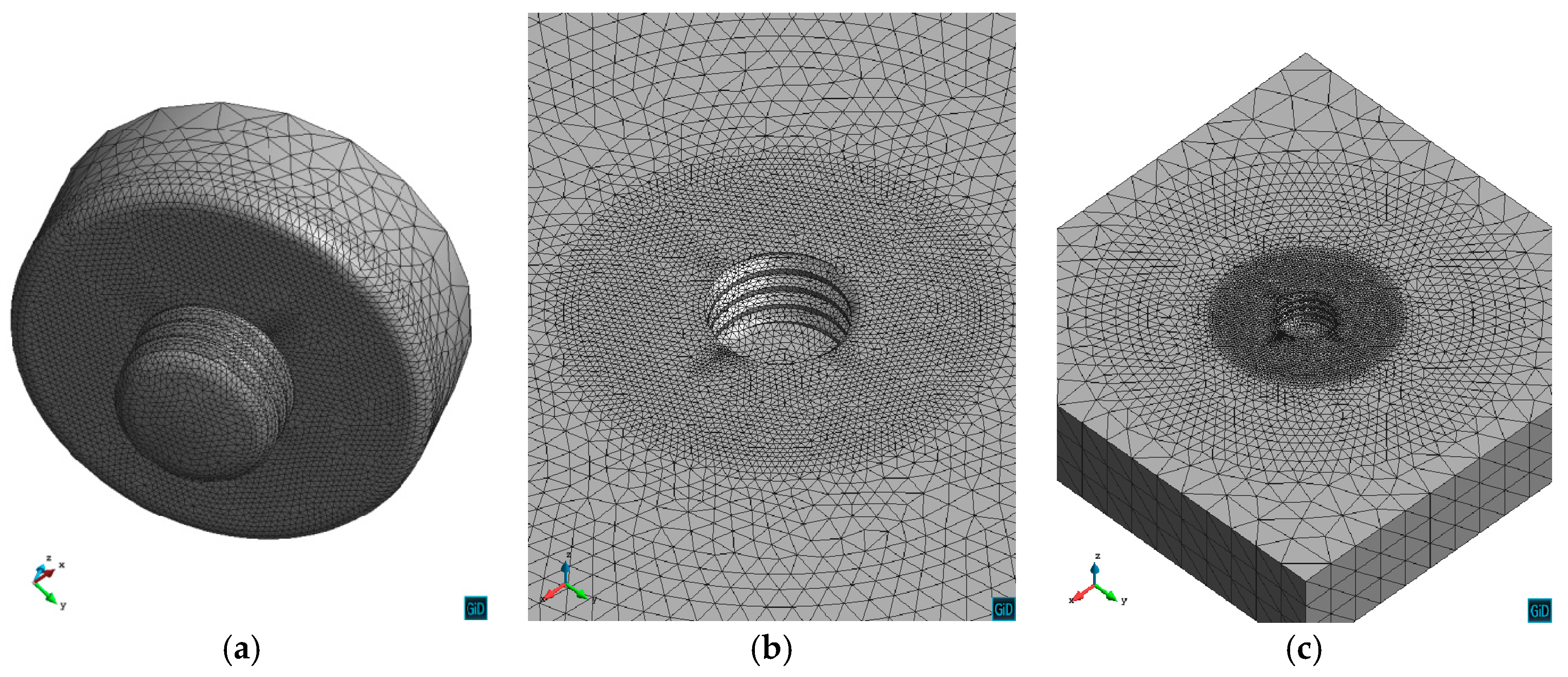
The mesh used in the simulation consists of 70,000 nodes and 400,000 tetrahedral elements. The mesh resolutions at the tool and the workpiece are shown in
Figure 5. A finer mesh is used in the vicinity of the pin-tool to capture the high temperature gradient in the TMAZ and to accurately define the geometry details.
In order to boost the convergence rate of this highly non-linear and coupled thermo-mechanical problem, a piecewise linearized Norton-Hoff model for different temperatures and strain rate values is assumed [
14].
The agreement between the resulting values of torques, longitudinal, transversal and vertical forces obtained from the numerical model and the experimental measurements is significantly noticeable. Thanks to the friction model proposed by the authors, the overall numerical model is able to predict the transversal forces in agreement with the experimental data, while the commonly used friction laws such as Coulomb or Norton are incapable of capturing it [
15]. In this work, the effect of the non-uniform pressure distribution below the tool translates into a non-uniform distribution of plastic dissipation, temperatures and friction tractions. This non-uniformity allows for the development of the transversal force up to the actual value recorded in the experimental measurements. Both experimental and numerical outcomes predict transversal forces higher than longitudinal forces.
Hence, the proposed framework for the numerical simulation of FSW process is capable of capturing accurately the mechanical results (
Table 3). This also vouches for the robustness of our friction model proposed for the FSW.
The total processing time on an Intel core i7 processor is approximately 10 h.
Figure 6 illustrates the temperature evolution at the four thermocouples located in the workpiece. In this figure, the comparison between numerical (Num) and experimental (Exp) results is presented. The response of the numerical model is found to be in a good agreement with the experimental measurements. Both experimental and numerical outcomes predict higher maximum temperature in the weld line decreasing with distance from the weld line and top surface.
In this work, the experimental data is provided at steady-state. Therefore, the transient simulation is performed until the (periodic) steady-state is reached. The maximum temperature recorded during the welding provides information indicating whether the process has attained the (periodic) steady-state [
21,
22]. Under these conditions, a comparison between the temperature fields obtained from the numerical simulation and the experimental measurements is performed.
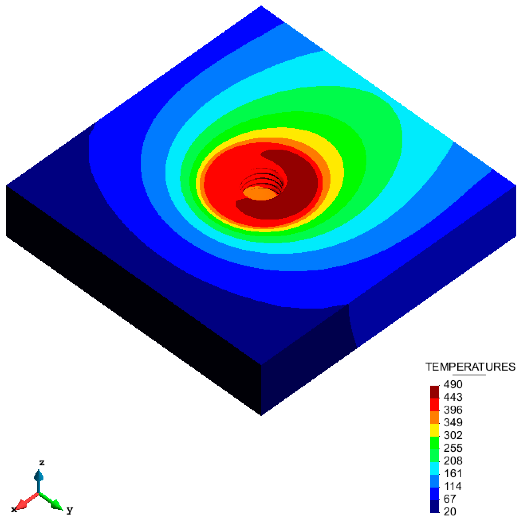
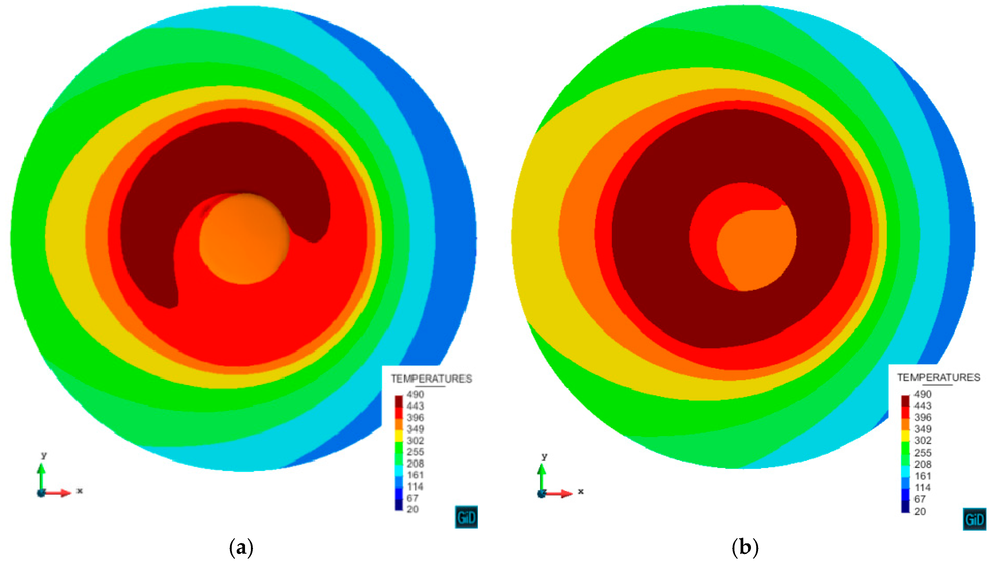
Figure 7 shows the temperature field at steady-state on the workpiece surface. The temperature distribution reveals a lower temperature at the head of the pin than the rear side. Thus, the flow stress is higher where the material is hotter.
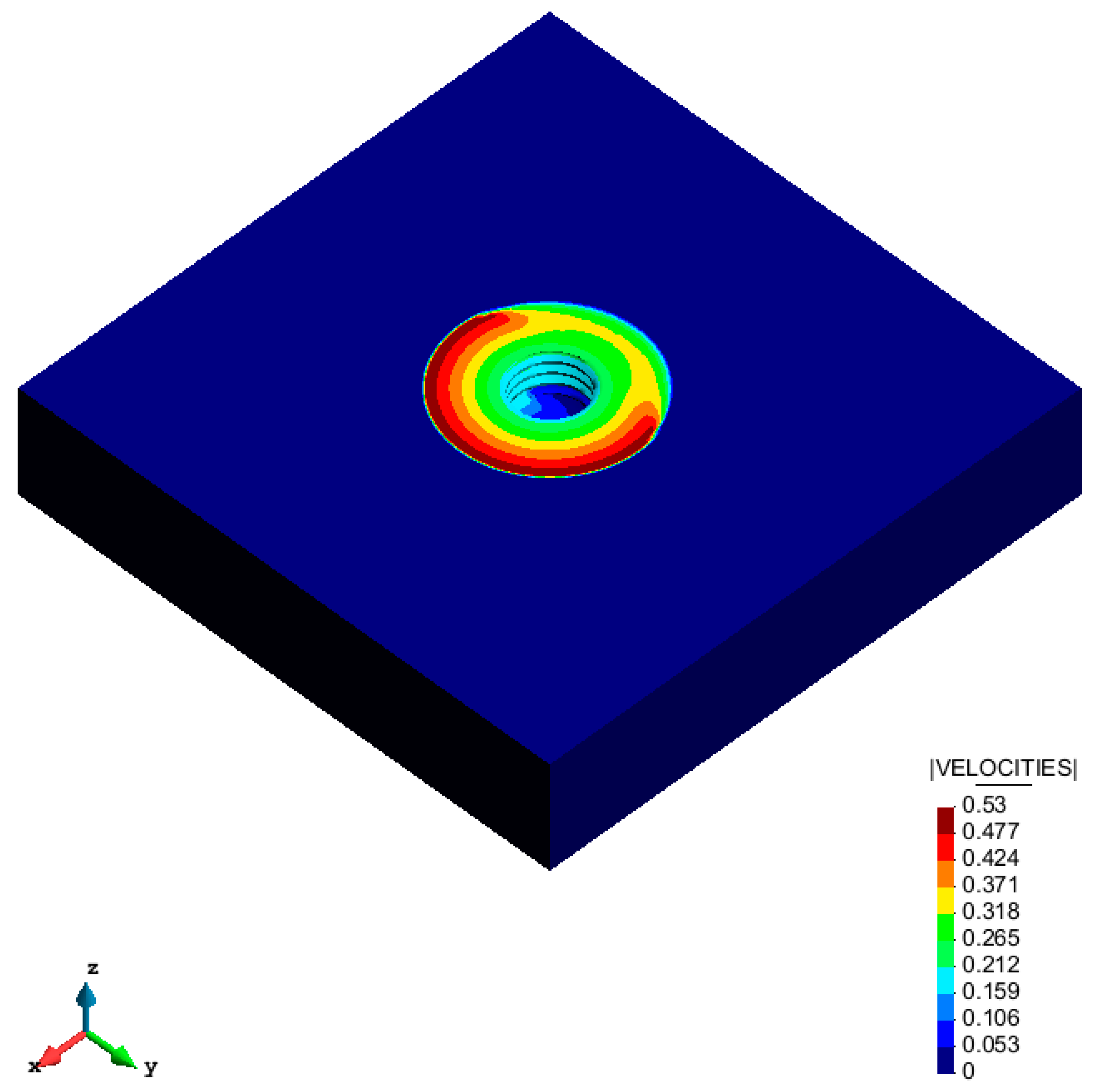
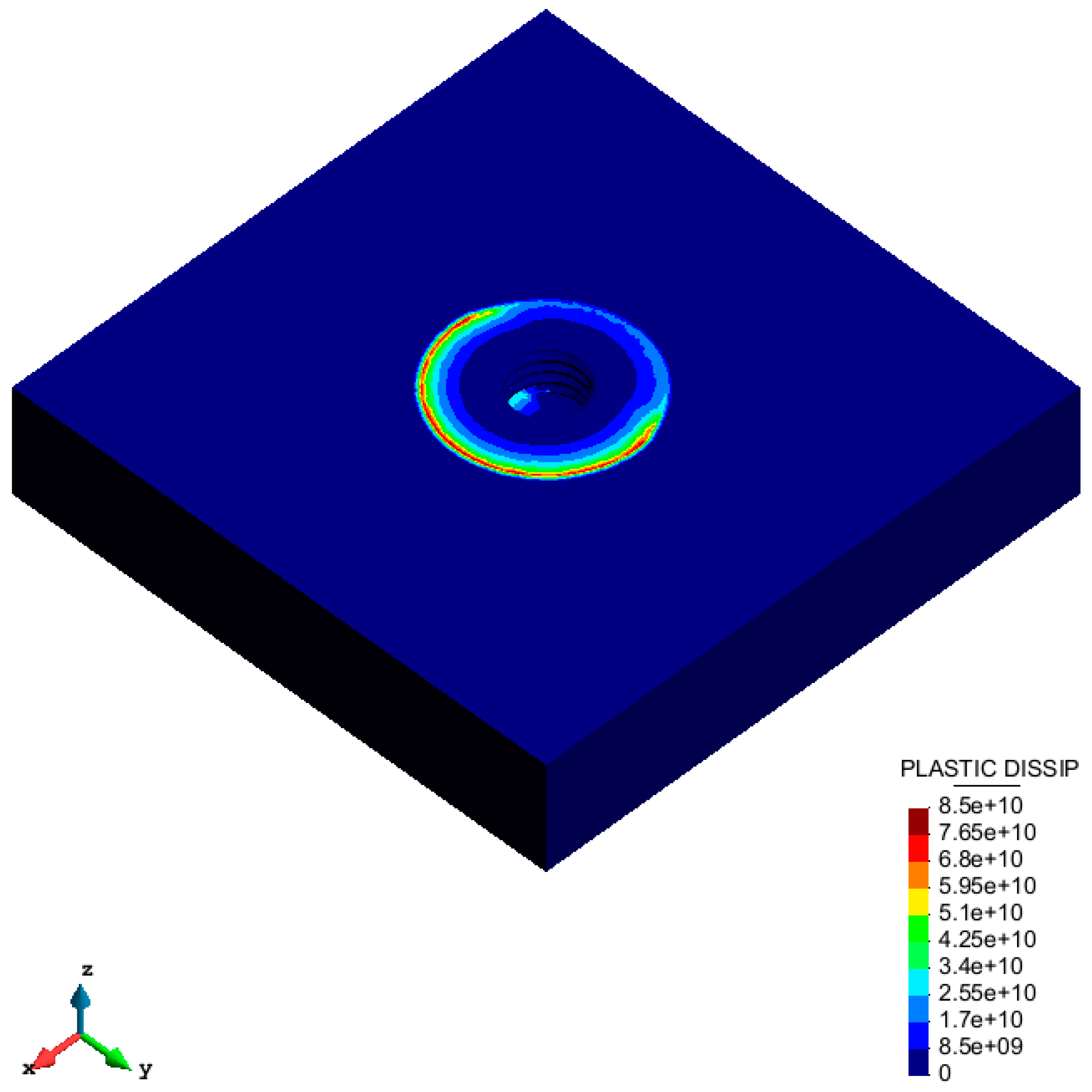
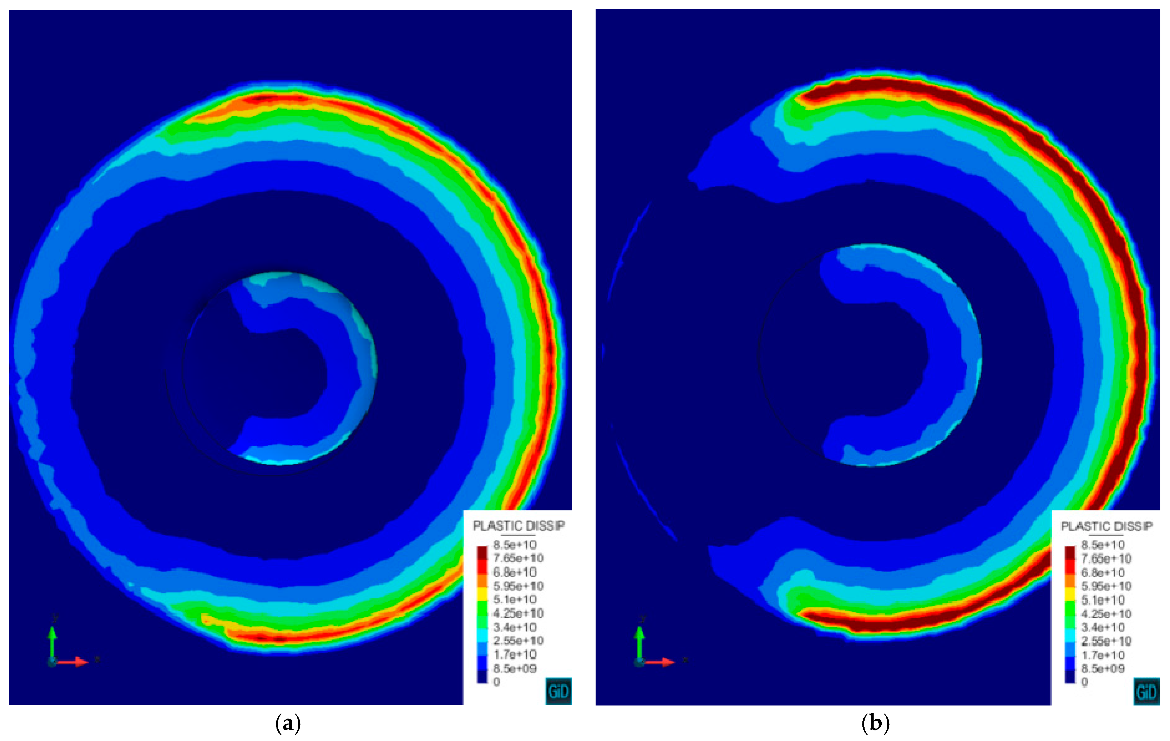
Figure 8 and
Figure 9 show the velocity and plastic dissipation contour fills computed from the numerical model. It can be clearly seen that the numerical model is able to represent the non-uniform distribution of the mentioned fields due to the use of the enhanced friction model. This non-uniformity results in the appearance of the transversal forces exerted on the tool.
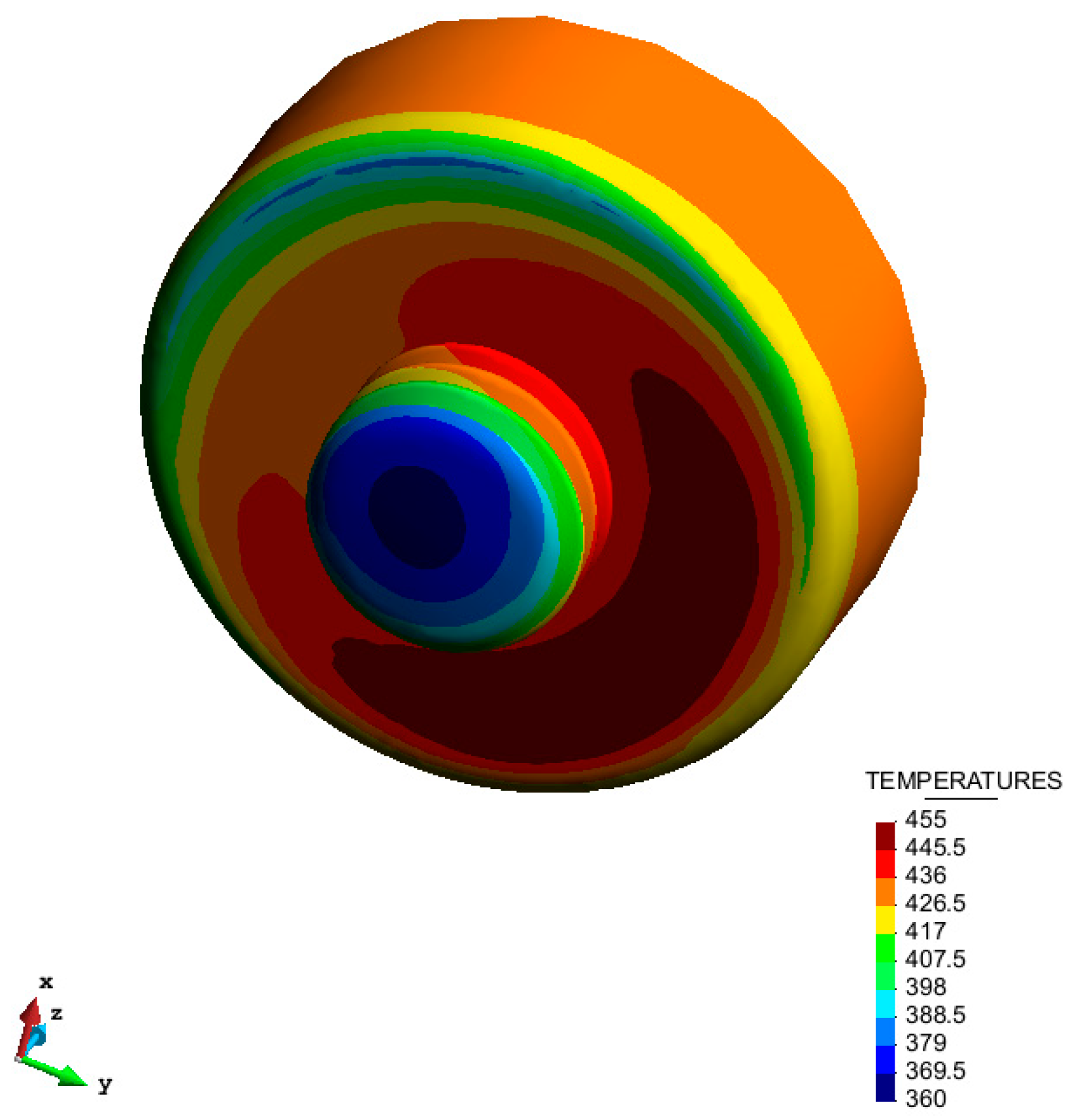
The temperature contour fill on the tool surface is displayed in
Figure 10. Note that the temperature varies between 360 °C and 455 °C. This shows that the temperature dependent parameters of the material and friction models vary only within this range of temperature at the TMAZ.

 ,
, 


