Article

Microstructure and Wear Resistance of Laser-Clad (Co, Ni)61.2B26.2Si7.8Ta4.8 Coatings

Key Laboratory of Materials Modification by Laser, Ion and Electron Beams (Ministry of Education), School of Materials Science and Engineering, Dalian University of Technology, Dalian 116024, China
*
Authors to whom correspondence should be addressed.
Metals 2017, 7(10), 419; https://doi.org/10.3390/met7100419
Submission received: 12 August 2017 / Revised: 22 September 2017 / Accepted: 25 September 2017 / Published: 7 October 2017

Abstract

:
It has been reported that a quaternary Co61.2B26.2Si7.8Ta4.8 alloy is a good glass former and can be laser-clad to an amorphous composite coating with superior hardness and wear resistance. In this paper, alloys with varying Ni contents to substitute for Co are coated on the surface of #45 carbon steel using a 5-kW CO2 laser source for the purpose of obtaining protective coatings. In contrast to the quaternary case, the clad layers are characterized by a matrix of α-(Fe, Co, Ni) solid solution plus CoB, Co3B, and Co3Ta types of precipitates. The cladding layer is divided into four regions: Near-surface dendrites, α-(Fe, Co, Ni) solid solution plus dispersed particles in the middle zone, columnar bonding zone, and heat-affected area that consists of martensite. The hardness gradually decreases with increasing Ni content, and the maximum hardness occurs in the middle zone. Both the friction coefficient and wear volume are minimized in the alloy containing 12.2% Ni. Compared with the previous cobalt-based quaternary alloy Co61.2B26.2Si7.8Ta4.8, the addition of the Ni element reduces the glass-forming ability and henceforth the hardness and wear resistance of the clad layers.

1. Introduction

Amorphous alloys, in comparison with their crystalline counterparts, show combinations of high strength, hardness, wear resistance, and corrosion resistance due to their special structures and chemical compositions [1,2,3,4,5]. However, their applications are still restricted by the stringent rapid-cooling preparation processes which produce in general only micron-sized ribbons, filaments, and powders.
Laser cladding offers a suitable materials synthesis method that easily prepares thick amorphous-based coatings on any metal surfaces via local rapid heating and cooling [6]. Due to the extremely non-equilibrium solidification condition during laser cladding, the clad layers are usually partially amorphous, whose presence is important for good toughness. The laser-clad materials are therefore bulk metallic glasses (BMGs) of high glass-forming abilities (GFAs) in order to obtain as much amorphous content as possible. In recent years, many research works have been conducted to prepare Zr-, Cu-, Ni-, Co-, and Fe-based amorphous composite coatings using this technique [7,8,9,10,11,12]. Among the many amorphous alloy systems, transition metal-metalloid-based BMGs are the most promising to be used for laser cladding materials due to their high GFAs as well as wear and corrosion resistance properties. It is noted especially that Co-based BMGs show excellent mechanical properties (in fact, the highest strength for metals has been achieved in a Co-based bulk metallic glass) [13].
In an earlier work by our group, a Co-based amorphous alloy with the composition of Co61.2B26.2Si7.8Ta4.8 was developed based on the cluster line criterion, whose glass transition temperature (Tg) is 926 K, supercooled liquid region width ΔTx is 31 K, and melting point (Tm) is 1350 K [14]. Because of its high glass transition temperature and wide super cooled liquid region, the alloy shows a high GFA with a critical glass rod diameter of 5 mm and has high hardness (14.43 GPa), which make it promising for laser cladding material. After being laser clad on a carbon steel containing 0.45 wt % C, a 1.0 mm thick layer was obtained that showed excellent mechanical properties, with the micro-hardness reaching 16.18 GPa and the friction coefficient 0.35–0.39 (against GCr15 ball), in sharp contrast to the corresponding 2.39 GPa and 0.59 of the #45 steel substrate [15]. According to Zhu et al. [16], the glass formation might be further enhanced by adding Ni, and the largest glassy critical size could reach Φ5 mm × 20 mm. Keeping in view of this previous work, the original quaternary Co61.2B26.2Si7.8Ta4.8 can be alloyed with different amounts of Ni in substitution for Co, (Co,Ni)61.2B26.2Si7.8Ta4.8. In the present work, these Co-Ni-B-Si-Ta alloy series will be laser-clad on carbon steel containing 0.45 wt % C and the effect of Ni additions will be specially focused on.

2. Design of the Cladding Material

A Co61.2B26.2Si7.8Ta4.8 alloy coating with a high fraction amorphous phase was obtained by laser cladding on #45 steel substrate, showing excellent mechanical properties [15]. Both Ni and Co have similar atomic radii and melting points. Based on the Co61.2B26.2Si7.8Ta4.8 original composition, four kinds of alloy composition were designed by using 6.1%, 12.2%, 18.4%, and 24.4% Ni to replace Co. In the following, these samples are named after their Ni contents. The choices of the Ni contents are to meet simple Co:Ni ratios of 9:1, 8:2, 7:3, and 6:4.

3. Experimental Materials and Procedure

A #45 medium carbon steel (carbon content ~0.45 wt %) with a dimension of 30 mm × 20 mm × 10 mm was selected as the substrate material. Master alloys with nominal composition were prepared by arc-melting in an argon atmosphere. The master alloy was re-melted four times to ensure compositional homogeneity, and then continuous ribbon samples were made by using a single-roller melt-spinner (CDZK Ltd., Chengdu, China) at surface copper wheel velocities of 40 m/s, with the 18 A of the electric current and the distance of the nozzle to roller being 3 mm, which were chosen as the cladding powders. The thickness and the width of the melt-spun ribbons were about 45 μm and 2 mm, respectively. Then, the quench strip was ground to a silver-white powder with a particle size of about 50 μm.
The cladding powders were pre-placed on the surface of the #45 medium carbon steel, forming a 1.0 mm thick layer, and were melted using a 5-kW continuous wave CO2 laser. The laser cladding was performed at a laser power of 3.0 kW with a laser beam diameter of 3 mm and a scanning velocity of 3 mm/s. Argon gas was blown into the melt pool to provide shielding during the laser cladding.
The microstructure and composition of the coatings were analyzed using a JEOL-5600LV scanning electron microscope (SEM; JEOL Ltd., Tokyo, Japan). The microscopy samples were etched using a mixture of 5 mL HNO3 + 15 mL HCl + 10 mL C2H4O2 prior to testing. Phase identification of the coatings was carried out through SHIMADZUXRD-6000 X-ray diffraction (XRD; Shimadzu Ltd., Tokyo, Japan) equipped with a Ni filter, Cu Kα radiation operating at 40 kV and 30 mA.
The micro-hardness of the cross-section of the coatings was measured using a DMH-2LS micro-hardness tester (Matsuzawa Co., Ltd., Akita, Japan) under a load of 0.98 N and a dwell time of 15 s. The samples with 10 mm × 10 mm × 5 mm were cut from the coatings for the wear test, and then were ground on 1500 grit size emery paper to obtain the same surface finish. Tribological properties were measured through a CETR-UMT-2 testing machine (Center for Tribology Inc Bruker Nano Inc, Campbell, CA, USA). A bearing steel ball (GCr15) with a diameter of 5 mm and a hardness of HRC 55 (Rockwell hardness) was chosen as the wear couple. The experiment was performed at a normal load of 5 N, a sliding speed of 1.0 mm/s, a reciprocal sliding distance of 5 mm, and a wear time of 30 min.

4. Results and Discussion

4.1. Microstructure Characterization

Figure 1a schematically illustrates the preparation process of the clad alloy, showing the morphologies of the master alloy ingot, the melt-spun ribbons, and the ground powder. Figure 1b shows a schematic view of the formation of the clad layer. In the direction of the laser movement, the powder was instantaneously melted when irradiated by the laser, and then rapidly solidified to form a semicircular cladding layer on the path where the laser spot was swept. Figure 1c is a schematic diagram of the different cross-sectional areas of the cladding layer. Take the Co42.8Ni18.4B26.2Si7.8Ta4.8 composition as an example. Area A is a crystalline region with a thickness of about several tens of micrometers along the macroscopic contours by the outer edge of the cladding layer. The middle B region is a solid-solution zone plus precipitation with a range of 300–400 µm, where the light region is the solid solution matrix, and the precipitated phase is in the form of small equiaxed crystals. Region C is at the bottom of the cladding layer, in touch with the substrate. The characteristic columnar crystals grow in line with the direction of the heat flow. It can be seen that the coating obtained by laser cladding is organized in multi-layers. In the heat-affected zone, martensite structure gradually transforms to ferrite and pearlite structure under the influence of the temperature gradient.
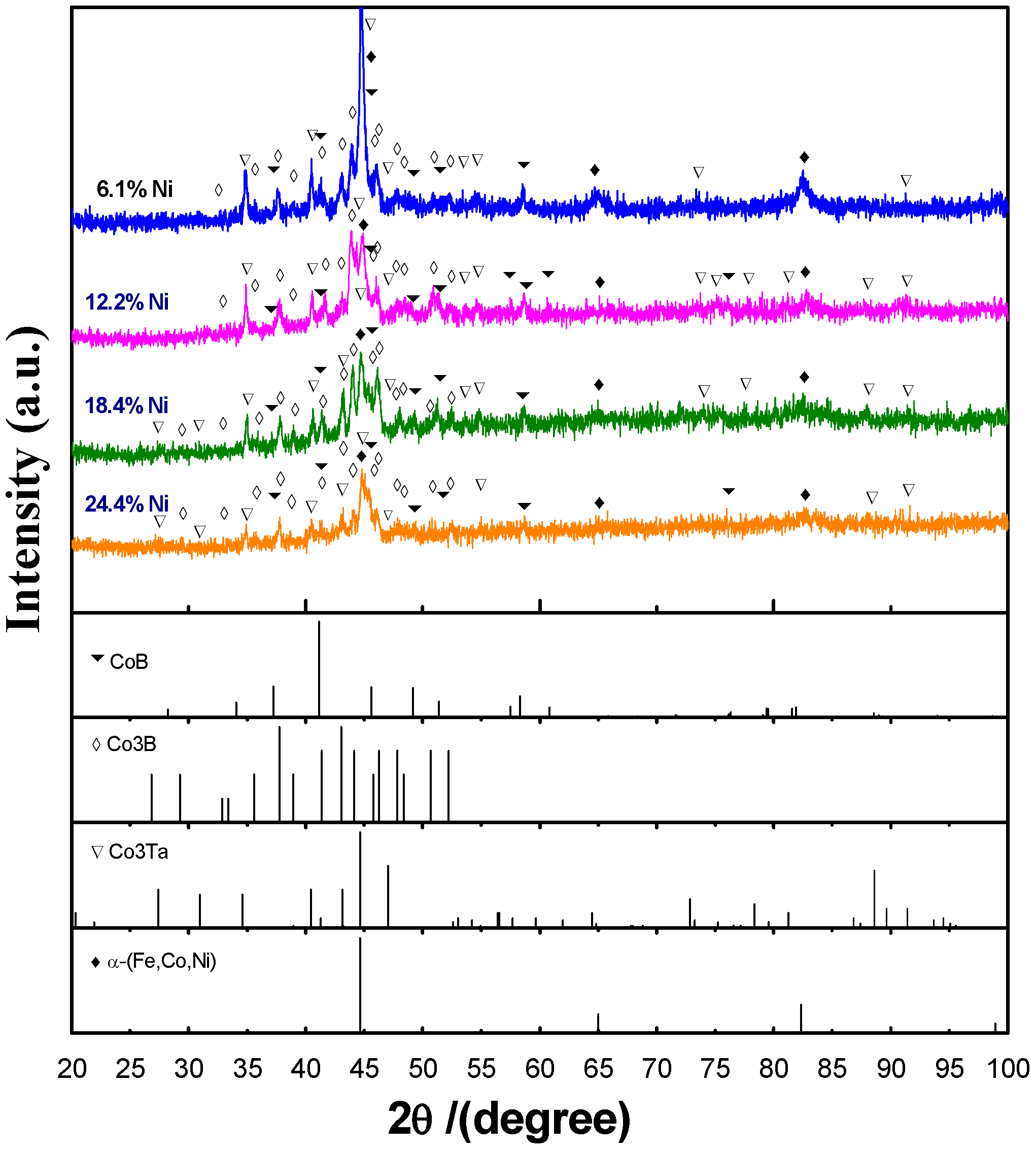
Figure 2 shows the X-ray diffraction patterns taken at a distance of 0.3 mm away from the top surface of the cladding layers. The patterns show strong peaks of α-(Fe, Co, Ni) plus CoB, Co3B, and Co3Ta (structural types only as they all contain Fe, Co, and Ni) phases. In sharp contrast to previous Co-B-Si-Ta cladding layers [15], here the amorphous phase is absent, which may be caused by the notable melting of the substrate carbon steel that dilutes the clad alloys.
Figure 3 shows SEM images of the typical cross-section morphologies at different zones of the four coatings. In the surface area of each cladding layer, with the increasing of Ni content, the microstructure is refined. The middle of the cladding layer consists of precipitates on α solid solution background without contrast. The bottom of the cladding layer, that is, the bonding zone, is also the region with the largest dilution and temperature gradient. The formation of these different solidified structures is determined by the interface shape stability factor, solid-liquid interface temperature gradient, solidification rate, etc. [17]. It can be seen that the increase of Ni is beneficial to grain refinement.

4.2. Mechanical Properties

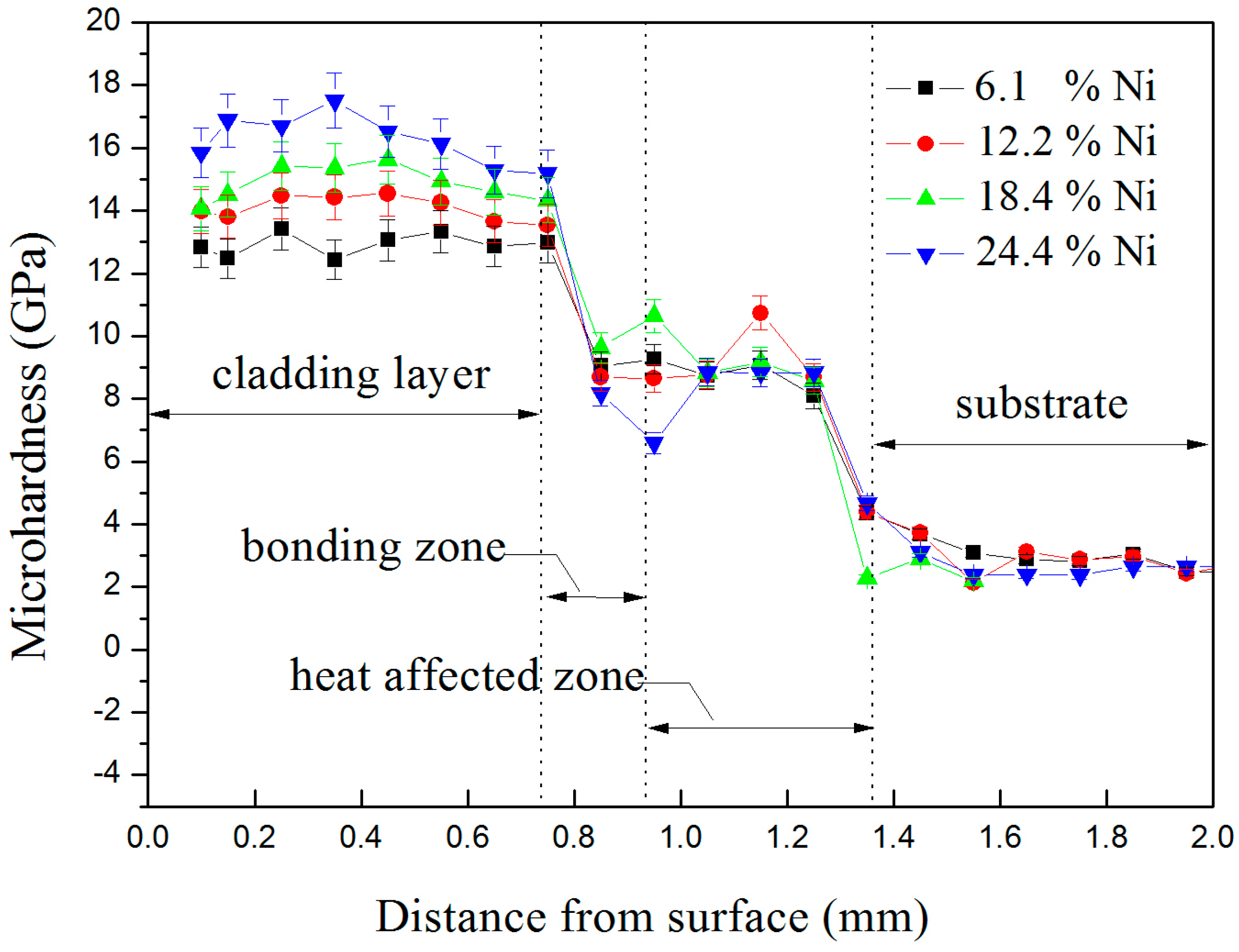
Figure 4 is the micro-hardness distribution along the depth direction for the four alloys with different Ni contents. In correspondence with the middle zone, bonding zone, and the heat-affected zone, the micro-hardness also decreases along the depth direction with obvious three-stair drops. The middle zone, consisting of the α-(Fe, Co, Ni) matrix strengthened by intermetallic compounds, shows the highest hardness. The bottom zone is softened by the Fe dilution from the substrate, which has the same hardness as the heat-affected zone. The dendrite surface layer, too thin, is not measured. In the previous research work, the Co61.2B26.2Si7.8Ta4.8 quaternary alloy amorphous rod hardness value was 14.5 GPa [14] and the maximum value of the laser-clad layer reached 15.9 Gpa [15]. When the Ni element is added, the present cladding layers also exhibit hardness values on the same level, with the 6.1% Ni sample showing the highest hardness of about 17 GPa and the 24.4% Ni sample showing the lowest hardness of about 13 GPa.
The average friction coefficient and wear volume of the four kinds of coatings are shown in Figure 5. It can be seen that the highest friction coefficient as well as the maximum wear volume appear when the Ni content is 6.1%, in contrary to our expectation, as this is the hardest sample. The best performance is reached in the 12.2% Ni sample. When the Ni content varies between 12.2% and 24.4%, both the friction coefficient and wear volume increase only slightly. Under the same wear condition, the friction coefficient and the wear volume of the substrate are 0.59 and 1.95 × 10⁻⁴ mm3 [14], respectively, far higher than those of the studied coatings. By comparison with the result of the micro-hardness test, it can be seen that the higher average micro-hardness observed at the lower Ni addition does not exhibit the maximum tribological properties. This is probably because the abrasion resistance of the material is not only related to the hardness of the material, but also to other properties such as elasticity. In contrast to the results of the quaternary alloy cladding, it was found that the hardness of the cladding layer is decreased in the Ni-containing quinary alloys, which may be caused by the formation of the major α solid solution matrix phase after substrate melting during laser cladding.
In order to identify the mechanism underlying the above change, the wear morphology of the alloy coating surface was further observed by scanning electron microscopy. It was revealed that the worn surface of the alloy coating was characterized by abrasive wear characteristics of furrows and debris which increased with increasing Ni contents, as shown in Figure 6. The 12.2% Ni sample shows the least amount of debris on the wear surface; however, the wear resistance is generally lowered in comparison with that of the amorphous composite coatings [14] due to the formation of the α solid solution matrix after substrate melting during laser cladding.

5. Conclusions

Four glass-forming alloys, Co55.1Ni6.1B26.2Si7.8Ta4.8, Co49.0Ni12.2B26.2Si7.8Ta4.8, Co42.8Ni18.4B26.2Si7.8Ta4.8, and Co36.8Ni24.4B26.2Si7.8Ta4.8, were laser-clad on a #45 steel substrate. The major phases in the middle zone were the α-(Fe, Co, Ni) solid solution matrix plus CoB, Co3B, and Co3Ta intermetallic phases. The average hardness of the cladding layer decreased with increasing Ni contents, with the highest micro-hardness being about 17 GPa in the 6.1% Ni sample. Both the minimum friction coefficient (~0.38) and wear volume (~6 × 10⁻⁴ mm3) were reached, however, in the softer 12.2% Ni sample.

Acknowledgments

This work is supported by the Natural Science Foundation of China (Grant No. 11674045) and the National Key Research and Development Program of China (Grant No. 2016YFB1100103).

Author Contributions

Cunshan Wang conceived and designed the experiments; Luan Zhang performed the experiments, analyzed the data, and wrote the paper; Shengnan Qian and Qun Yu provided assistance in the experiments; Chuang Dong discussed the results and modified the paper.

Conflicts of Interest

The authors declare no conflict of interest.

References

  1. Gaskell, P.H. Models for the Structure of Amorphous Metals. In Glassy Metal II; Beck, H., Güntherodt, H.J., Eds.; Springer-Verlag: Berlin/Heidelberg, Germany, 1983; Volume 53, pp. 5–49. [Google Scholar]
  2. Greer, A.L. Metallic glasses. Science 1995, 267, 1947–1953. [Google Scholar] [CrossRef] [PubMed]
  3. Inoue, A.; Takeuchi, A. Recent development and applications of bulk glassy alloys. Int. J. Appl. Glass Sci. 2010, 1, 273–295. [Google Scholar] [CrossRef]
  4. Qiao, J.; Jia, H.; Liaw, P.K. Metallic glass matrix composites. Mater. Sci. Eng. R Rep. 2016, 100, 1–69. [Google Scholar] [CrossRef]
  5. Wang, W.H.; Dong, C.; Shek, C.H. Bulk metallic glasses. Mater. Sci. Eng. R Rep. 2004, 44, 45–89. [Google Scholar] [CrossRef]
  6. Viswanathan, A. Laser Processing on Metals and Metal Alloys; VDM Verlag: Saarbrucken, Germany, 2010. [Google Scholar]
  7. Hong, X.; Tan, Y.; Wang, X.; Xu, T.; Gao, L. Microstructure and wear resistant performance of TiN/Zr-base amorphous-nanocrystalline composite coatings on titanium alloy by electrospark deposition. Surf. Coat. Technol. 2016, 305, 67–75. [Google Scholar] [CrossRef]
  8. Huang, K.; Xie, C.; Yue, T.M. Microstructure of Cu-based amorphous composite coatings on AZ91D magnesium alloy by laser cladding. J. Mater. Sci. Technol. 2009, 25, 492–498. [Google Scholar]
  9. Jin, Y.J.; Li, R.F.; Zheng, Q.C.; Li, H.; Wu, M.F. Structure and properties of laser-cladded Ni-based amorphous composite coatings. Mater. Sci. Technol. 2016, 32. [Google Scholar] [CrossRef]
  10. Chang, Z.K.; Gong, J.; Sun, C. Co-based Amorphous/nanocrystalline composite coatings deposited by arc ion plating. J. Mater. Sci. Technol. 2013, 29, 806–812. [Google Scholar] [CrossRef]
  11. Zhu, Q.J.; Wang, X.H.; Qu, S.Y.; Zou, Z.D. Microstructure and wear properties of laser clad Fe based amorphous composite coatings. Surf. Eng. 2009, 25, 201–205. [Google Scholar] [CrossRef]
  12. Hitit, A.; Şahin, H.; Öztürk, P.; Aşgın, A.M. A new Ni-based metallic glass with high thermal stability and hardness. Metals 2015, 5, 162–171. [Google Scholar] [CrossRef]
  13. Inoue, A.; Shen, B.L.; Chang, C.T. Fe-and Co-based bulk glassy alloys with ultrahigh strength of over 4000 MPa. Intermetallics 2006, 14, 936–944. [Google Scholar] [CrossRef]
  14. Zhu, C.L.; Wang, Q.; Wang, Y.M.; Qiang, J.B.; Dong, C. Co-B-Si-Ta bulk metallic glasses designed using cluster line and alloying. J. Alloys Compd. 2010, 504, 34–37. [Google Scholar] [CrossRef]
  15. Zhang, L.; Wang, C.S.; Han, L.Y.; Dong, C. Influence of laser power on microstructure and properties of laser clad Co-based amorphous composite coatings. Surf. Interfaces 2017, 6, 18–23. [Google Scholar] [CrossRef]
  16. Zhu, C.L. Compositions Design and Properties of (Co,Ni,Fe)-B-Based Bulk Metallic Glasses Designed from Eutectic Cluster Formulae. Ph.D. Thesis, Dalian University of Technology, Dalian, China, 16 January 2011. [Google Scholar]
  17. Kurz, W.; Fisher, D.J. Fundamentals of Solidification, 4th ed.; Trans Tech Publications Ltd.: Stafa-Zurich, Switzerland, 1998; pp. 86–88. [Google Scholar]
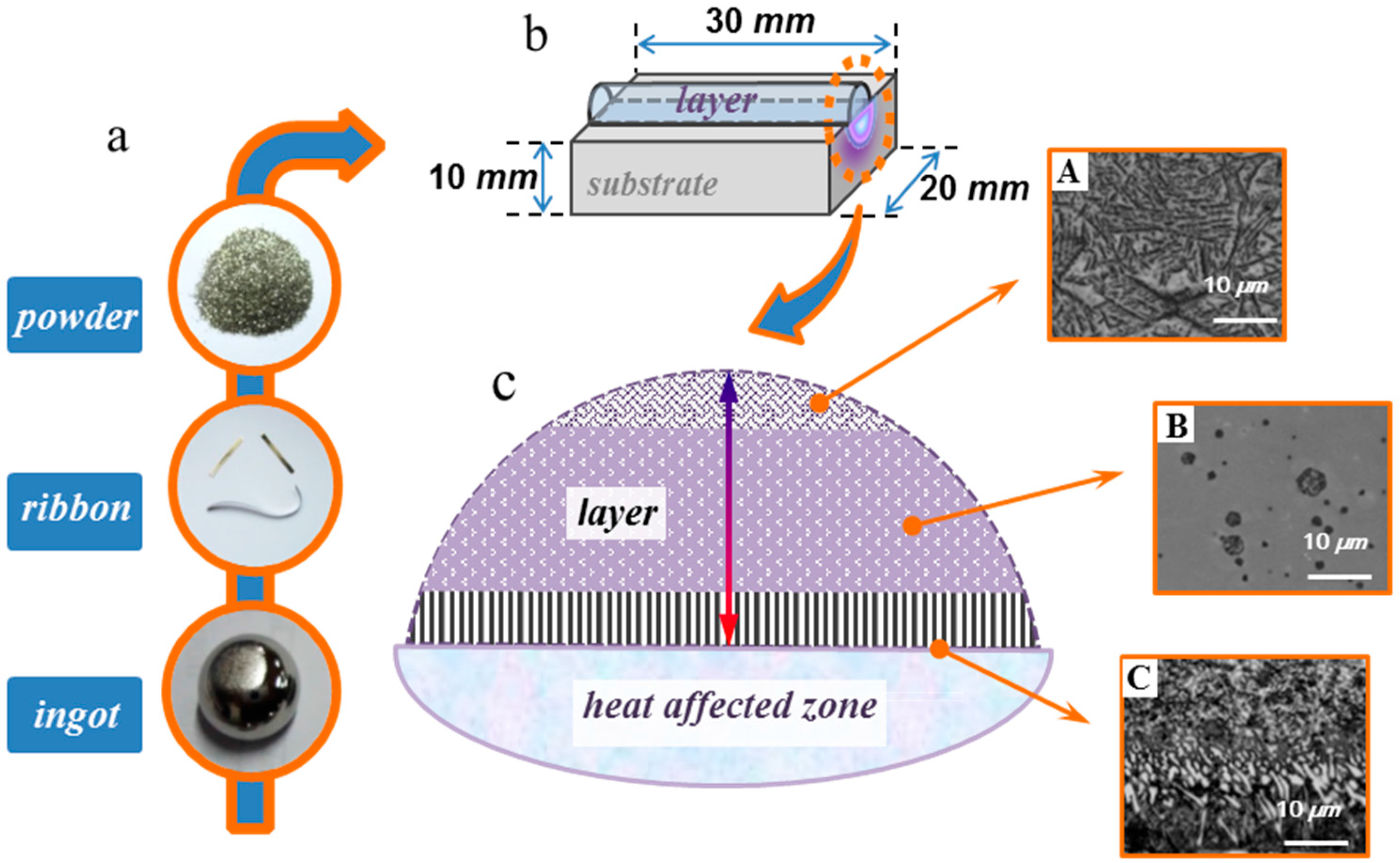
Figure 1. Laser cladding process including: (a) Preparation of the cladding alloy; (b) cladding sample; (c) cross-section views of different regions in the clad.
Metals 07 00419 g001
Figure 2. X-ray diffraction patterns with different Ni contents.
Metals 07 00419 g002
Figure 3. SEM images of the coating cross-section for 6.1% Ni, 12.2% Ni, 18.4% Ni, and 24.4% Ni.
Metals 07 00419 g003
Figure 4. Cross-section hardness curves of the Co-base alloy coatings with different Ni contents.
Metals 07 00419 g004
Figure 5. Curves of the friction coefficient and wear volume of the coatings with different Ni contents for 30 min.
Metals 07 00419 g005
Figure 6. The worn morphologies of the coatings with different Ni contents: (a) Co55.1Ni6.1B26.2Si7.8Ta4.8; (b) Co49.0Ni12.2B26.2Si7.8Ta4.8; (c) Co42.8Ni18.4B26.2Si7.8Ta4.8; (d) Co36.8Ni24.4B26.2Si7.8Ta4.8.
Metals 07 00419 g006