1. Introduction
In the field of applied biocompatible materials in medicine, there is continuous development [
1,
2,
3,
4]. The materials used for biomedical applications must exhibit certain specific characteristics, namely sufficient mechanical properties, corrosion resistance [
5,
6], and biocompatibility. For production reasons, their workability is also a matter of concern.
Titanium and Ti-based alloys are considered to be the most attractive metal materials for biomedical purposes and form a huge part of materials used in the construction of dental and orthopedic implants, as well as facial and plastic surgery [
7]. The strong point is its excellent biocompatibility. It has no allergic or sensitizing effect, and moreover is not carcinogenic or toxic. A layer of titanium oxide even gives bacteriostatic effect. Other beneficial properties of titanium alloys are their low electrical conductivity, high corrosion resistance, predictable thermodynamics, and good strength-to-weight ratio. Titanium has the ability to self-passivate in most corrosive environments, although it belongs to the non-noble metals with high negative potential (−1633 mV). The thickness of TiO
2 passivation layer varies between 20 and 50 nm, it protects the material against corrosion and ensures its bio-inertness. The advantage of this passivation layer is the self-restoration if broken e.g., during the machining of the material. Titanium passes either to the active state, namely in reducing environments with low pH, or in environments where soluble titanium complexes are formed. Hydride layer TiH
2 is formed under conditions with hydrogen depolarization. The layer has the same passivation ability at the small concentrations of non-oxidizing acids. The formation of a hydride or oxide layer is also linked with changes of titanium electrode potentials.
The resistance of titanium against certain substances can be increased either by changing the composition of the Ti alloy, surface treatment of the Ti alloy in various ways [
8], or by change in composition of a corrosive environment. The corrosive environment in biomedical applications is given by conditions in the intrabody environment, the change is not possible. The significant improvement of mechanical properties of Ti alloys can be achieved by alloying elements such as aluminum, vanadium, palladium, zirconium, chromium, and copper, however these components may not be tolerated by a human body environment [
9]. Another possibility of influencing the resistance of titanium alloys is a surface treatment, especially anodic oxidation. Utilizing suitable voltage can increase the resistance of titanium against some acids at elevated temperatures. Annealing also allows the increase of corrosion resistance of titanium alloys by forming a continuous surface layer of oxides. Another possibility is modifying the surface morphology of implants mechanically—abrasive blasting. Blasting enables to change the morphology of surfaces to roughen or smooth out according to individual requirements [
10,
11,
12]. Abrasive blasting lead to changes in a surface area size and roughness parameters, the removal of both the surface layers and the subsurface work hardening occur together with changes of mechanical properties and surface activity.
Blasting parameters influencing the quality of the surface, according to [
13]:
material and grain size of blasting abrasive,
distance between the surface and blasting nozzle,
abrasive impact angle,
abrasive velocity,
intensity of blasting (given by applied abrasive mass per area or by blasting time).
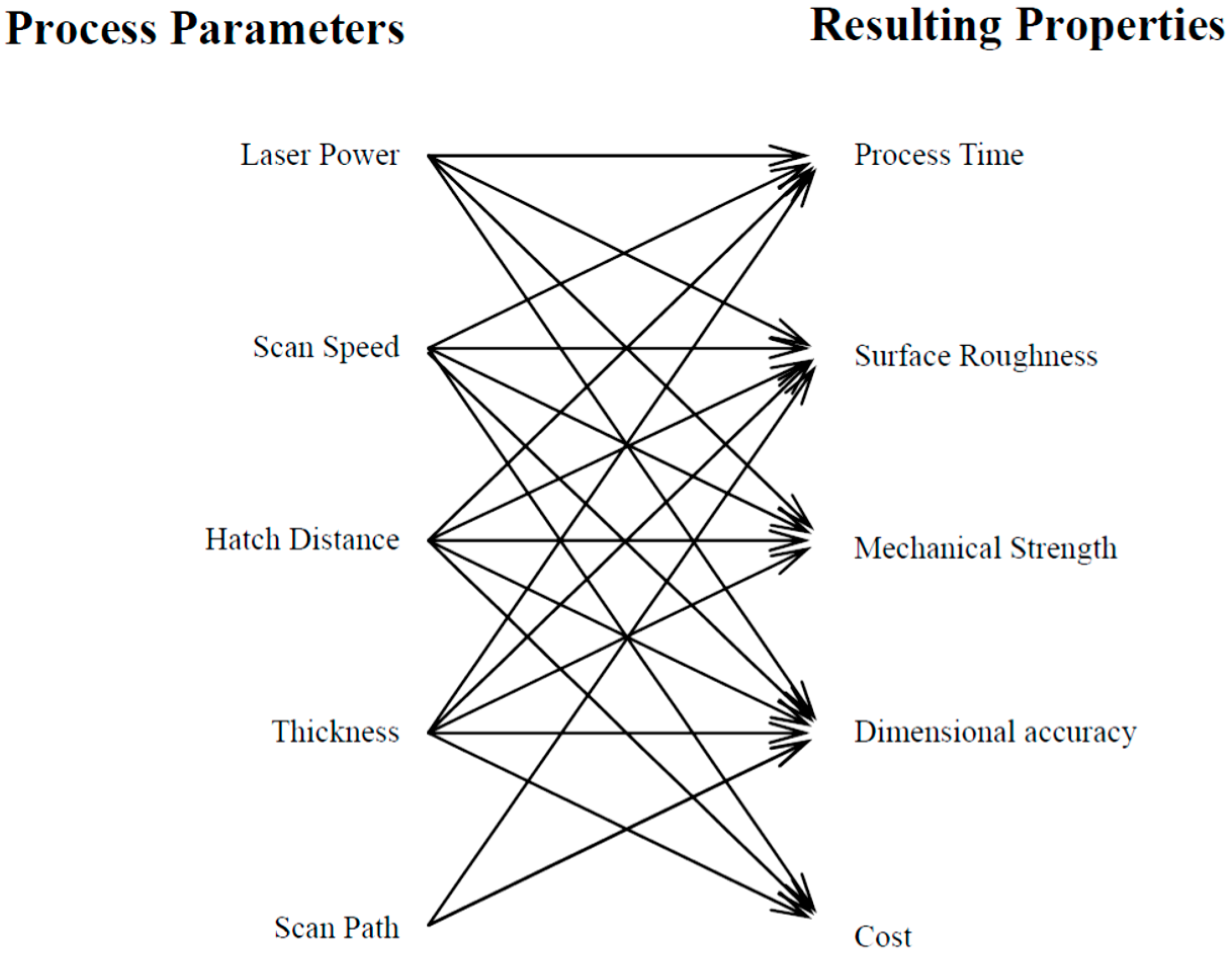
The technology and parameters of the production of the implants are also involved in the final properties,
Figure 1. Influence of particular DMLS parameters on the final implant properties was investigated by many researchers [
14,
15,
16,
17,
18,
19,
20]. Manufacturing of fitted implants are often implemented by a rapid prototyping (RP) technology, since each product possesses the unique shape. RP technologies are an additive technology using CAD models that transforms into thin horizontal layers and then shapes particular material to the final product. In DMLS (Direct Metal Laser Sintering) technology, remelting of powder with a laser beam occurs [
21,
22].
The aim of this paper is to determine the impact of the laser power in Ti6Al4V powder sintering on the microstructure, mechanical properties, and corrosion resistance of the final product. The opportunity to modify the surface morphology of implants by an abrasive blasting with two blasting abrasives is verified as well.
2. Materials and Methods
For the realization of experimental work, a powder of Ti6Al4V alloy has been used,
Table 1. This commercial powder had spherical morphology with an average particle size of 50 μm. Test samples were prepared by DMLS technology using EOSINT M280 (nominal power 200 W, EOS Electro Optical Systems, Munich, Germany),
Figure 2.
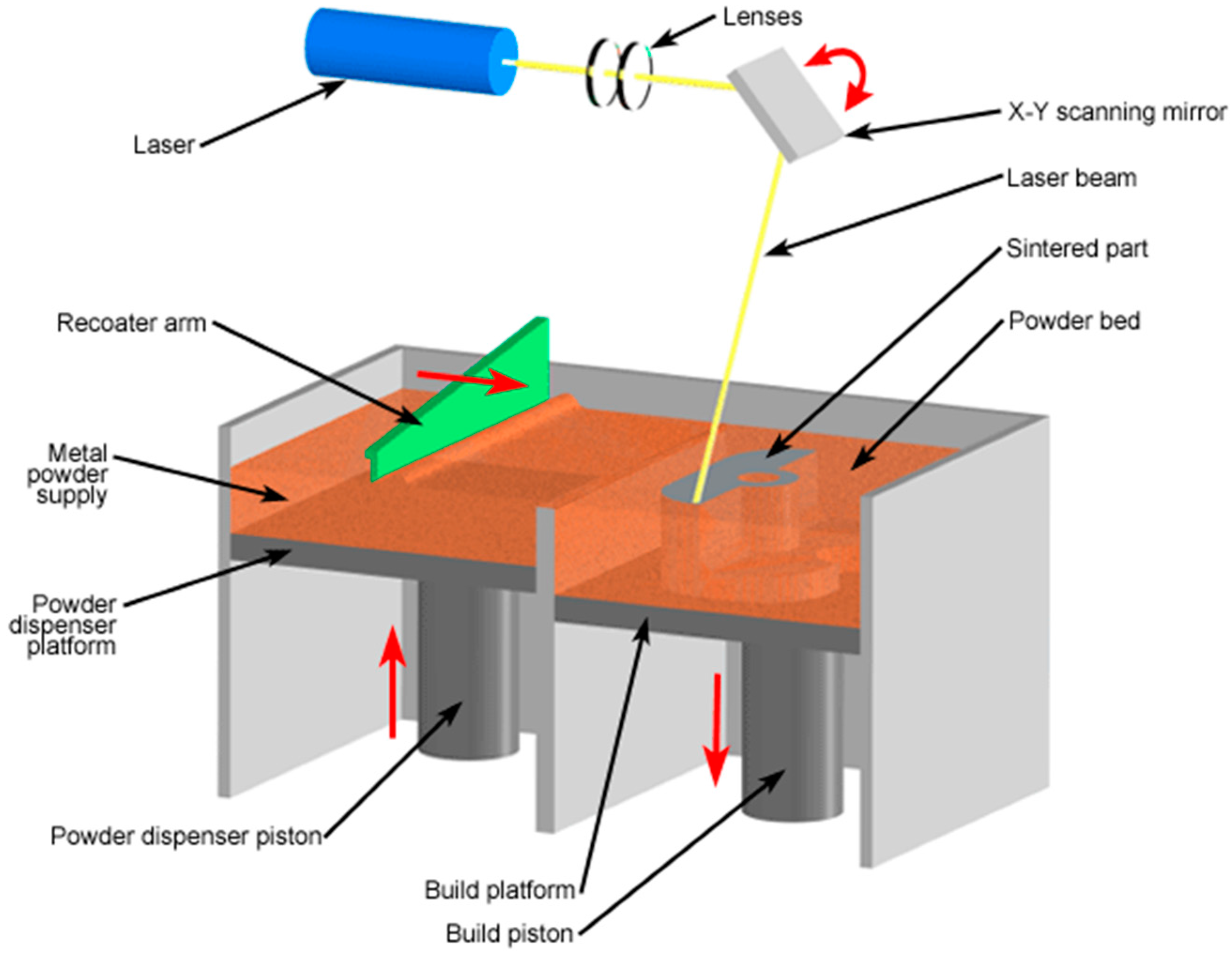
In DMLS technology the powder is provided to the working cylinder in a thin layer of a fixed thickness. Simultaneously, the powder surface in the working cylinder is scanned with a high-energy Yb-fiber laser system according a defined pattern. The scanner has a significant impact on the part accuracy. It guides the laser beam arriving from the beam expander optics along a defined path over the building area using two mirrors operated by galvanometers. An integrated autocalibration feature (home-in function) checks the mirror positions and regulates the positions if necessary. In this way offset drift and gain drift are significantly reduced. The laser beam is focused on the building area using an F-Theta objective.
The layer sintering process is repeated till the whole part is created. The powder is locally melted at the laser beam track and then solidified. A steel platform serves as structural support and heat dissipation during sintering. To protect from oxidation, the process takes place in an argon atmosphere.
3. Results
Microstructures of the materials sintered using different laser powers are shown in
Figure 6 and
Figure 7.
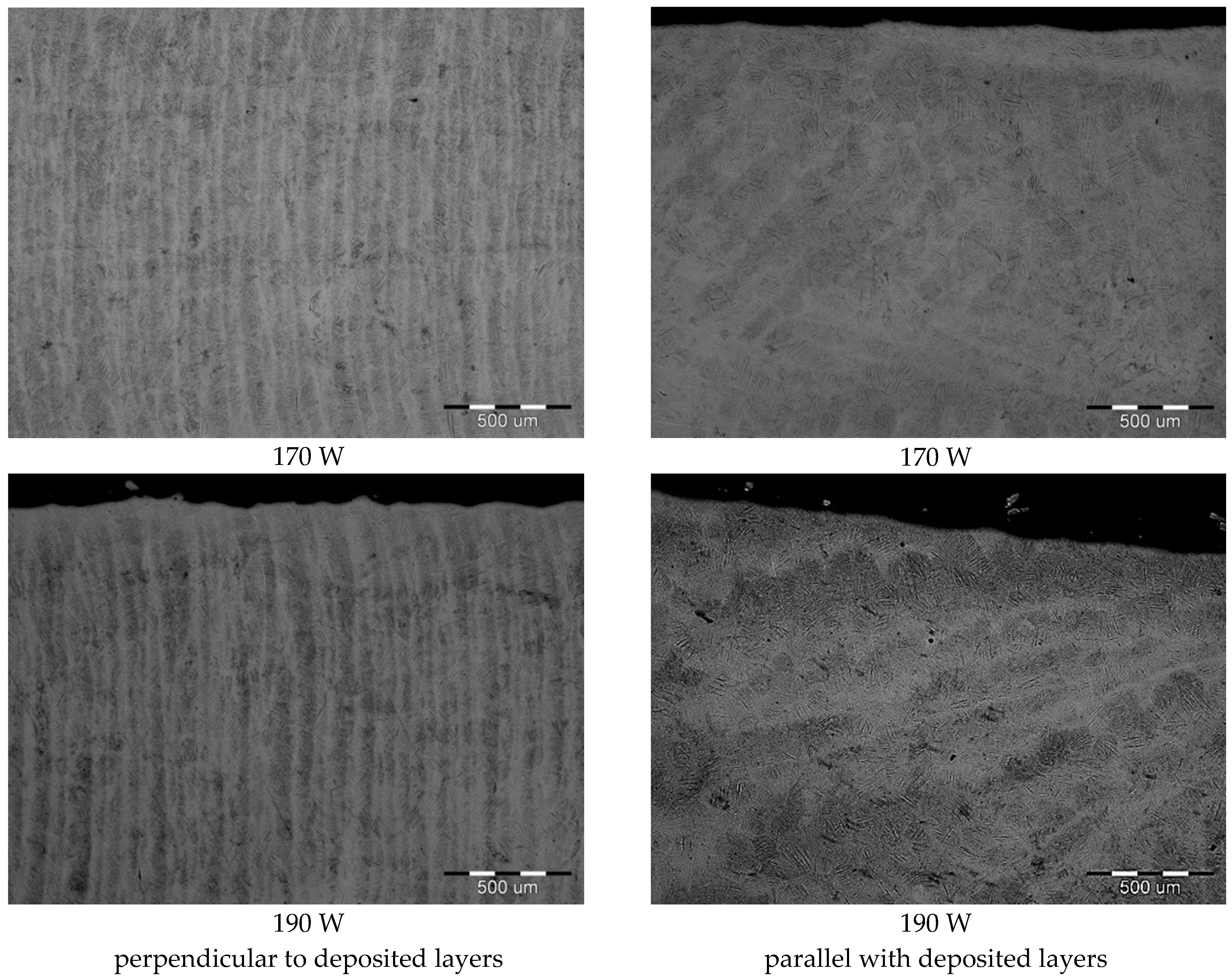
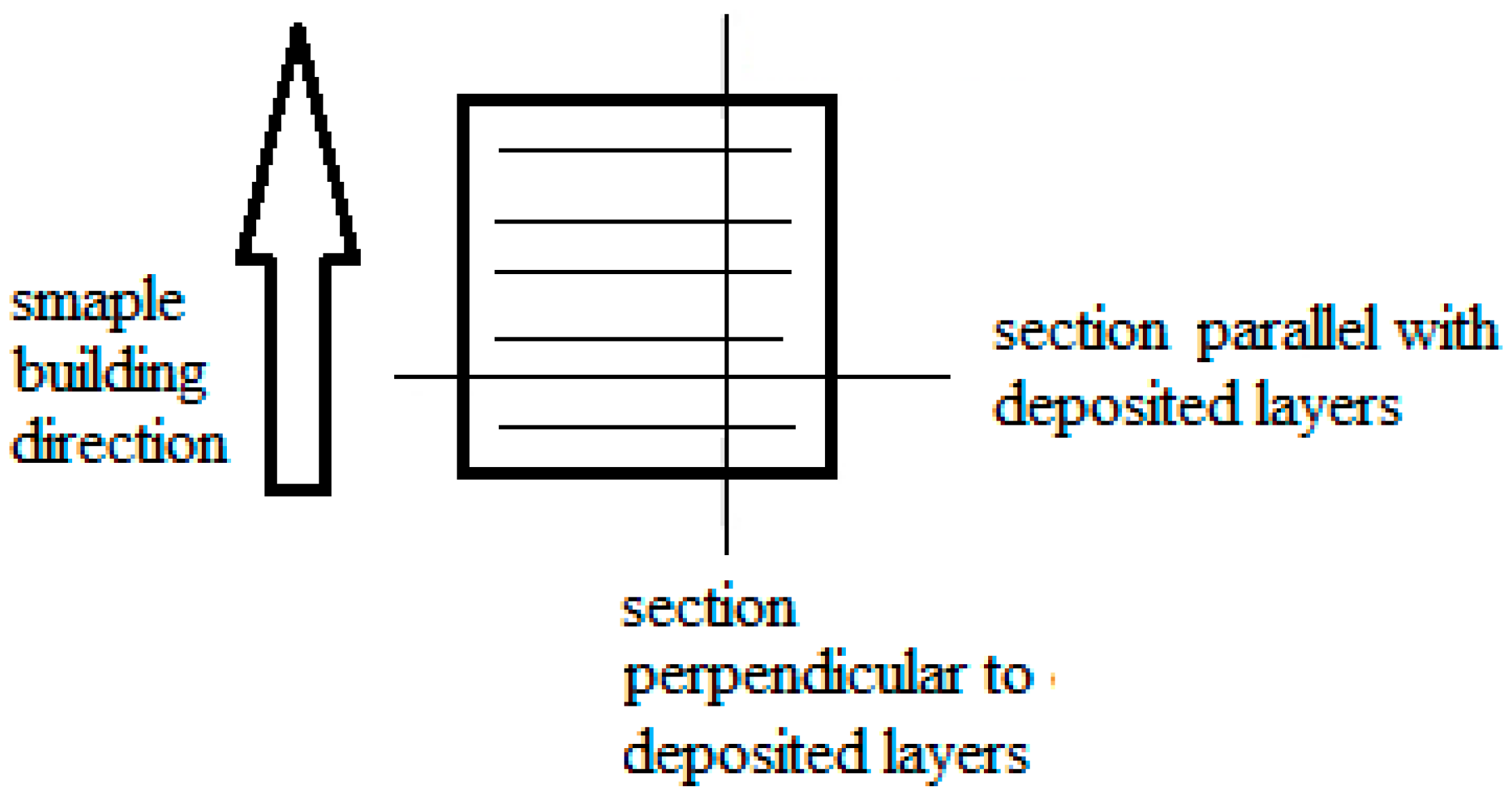
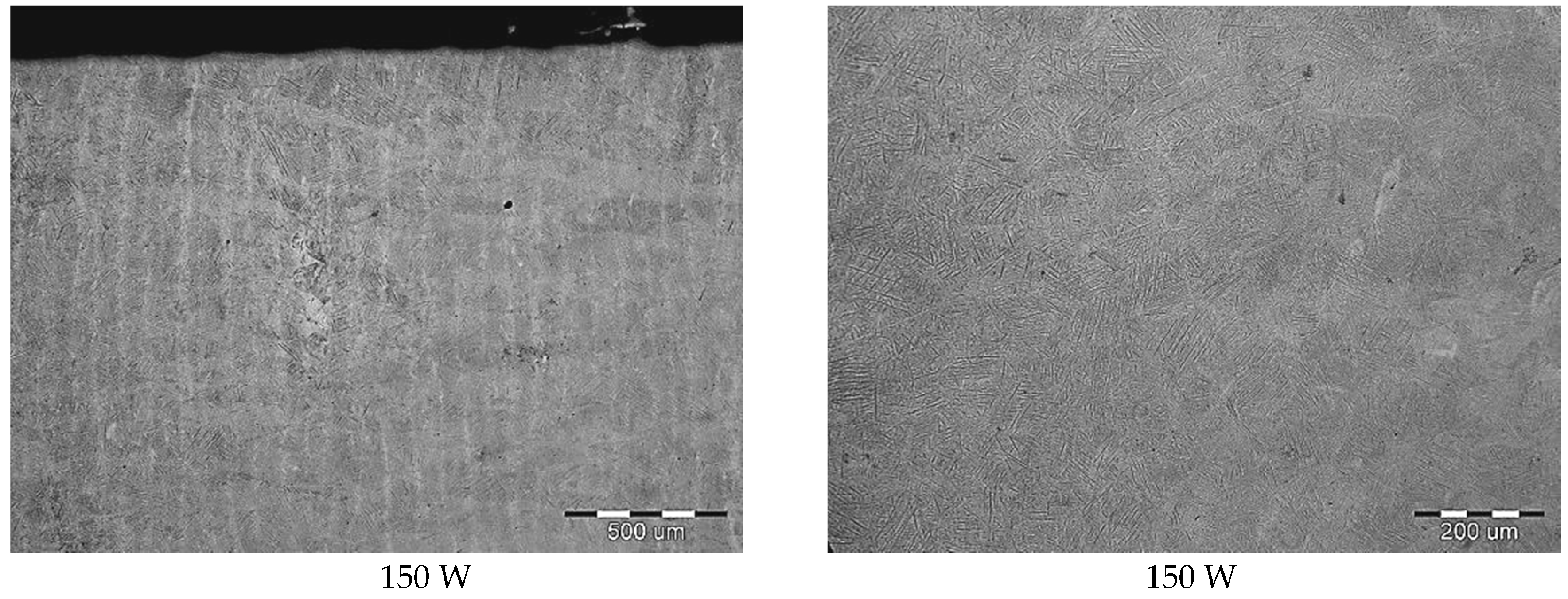
At low magnification (
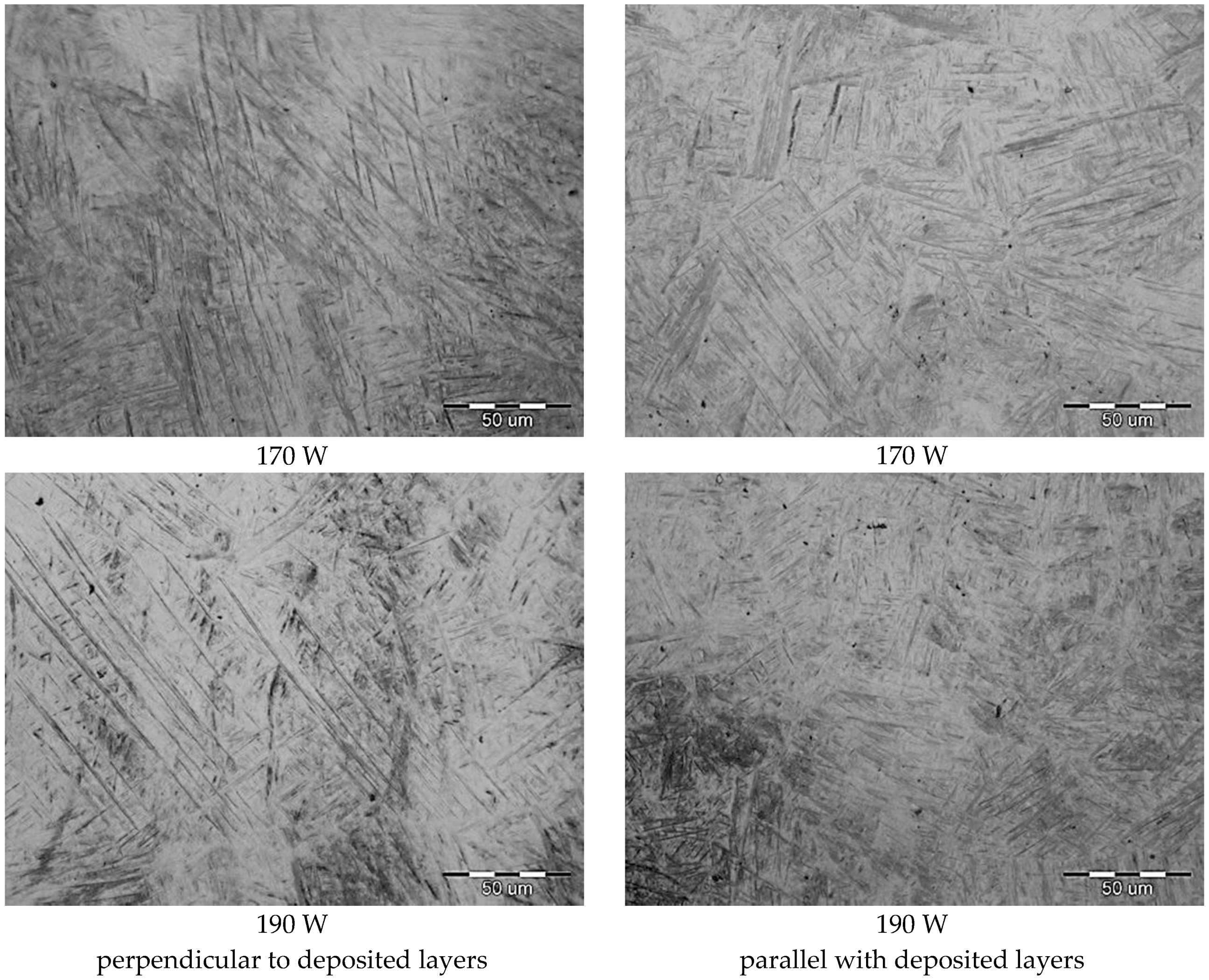
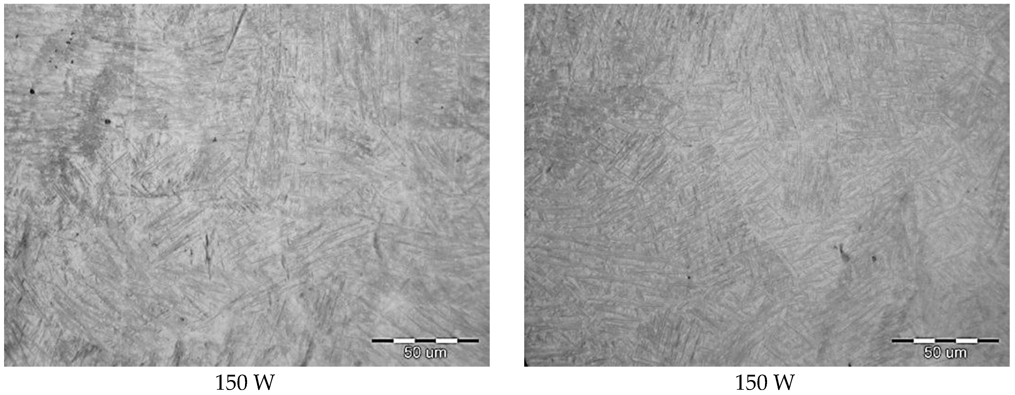
Figure 6), a pattern relating to sintering particular powder layers in section perpendicular to the layers deposition can be observed. The pattern appears to be columnar grains orientated to the direction of build. The microstructure of the sintered material at a magnification of 500× are shown in
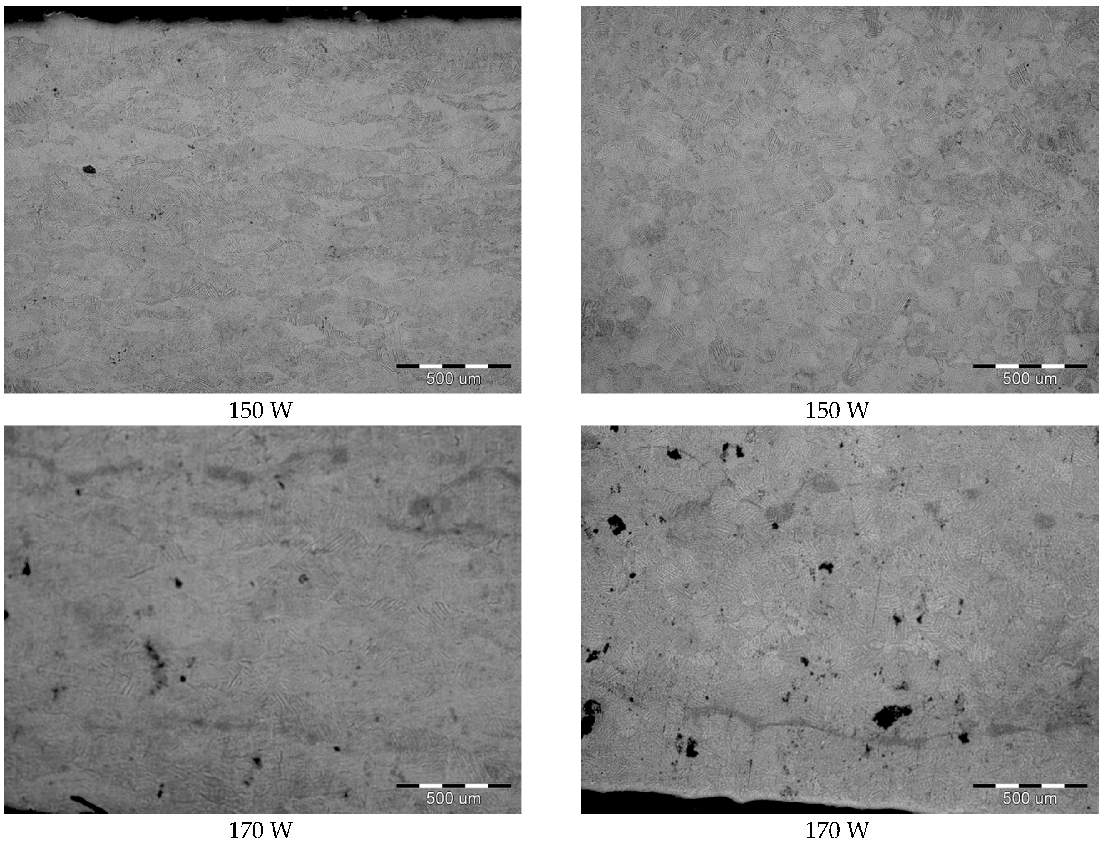
Figure 7.
Microstructure of materials after stress-relief annealing are shown in
Figure 8.
From metallographic analysis we can conclude:
annealing leads to structure pattern dissolving
due to the fact that the analyzed alloy is of (α + β)-type, the primary structure after sintering is lamellar, it has a fine morphology consisting of primary α phase and the acicular phase of probably α’-phase martensite, the rest of structure consists of β phase
in all analyzed materials, after annealing occurs, there is white acicular phase in the structure with a fishbone arrangement, the phase appears on the boundary of some original martensitic needles, although a significant amount of original martensite needles remain unchanged after annealin
since annealing was realized below α → β transition temperature, growth β of the phase has not been recorded
the structure in metallographic sections parallel with deposited layers before and after annealing is equiaxed polyhedric, without visible porosity, high density, and integrity of the material
microstructures do not show any significant differences with respect to different laser powers
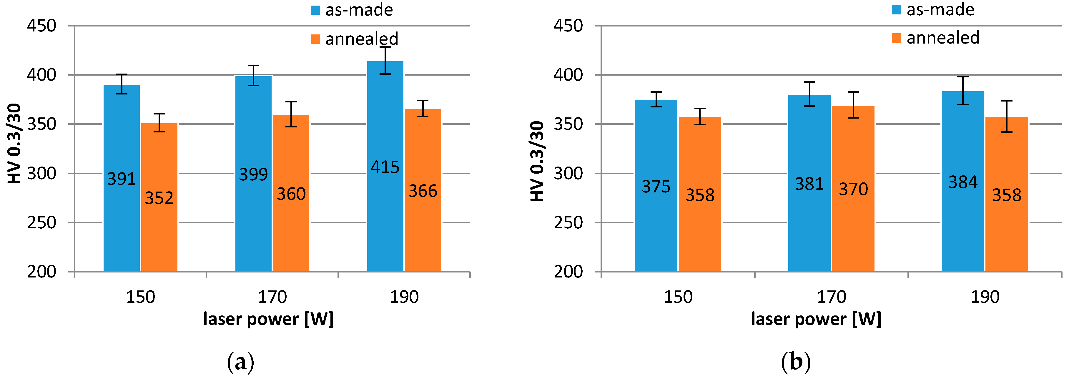
The hardness of sintered materials depending on the laser power measured in two directions is shown in
Figure 9.
The measured results showed the increase of laser power led to an increase in hardness of materials in both measuring directions. In the direction perpendicular to deposited layers there was recorded higher hardness than in parallel direction. After annealing, the hardness of materials for all laser powers and both measuring directions decreased. More remarkable decrease of materials hardness was recorded in perpendicular direction compared to parallel direction. This fact can due to dissolving of structure pattern and material structure homogenization.
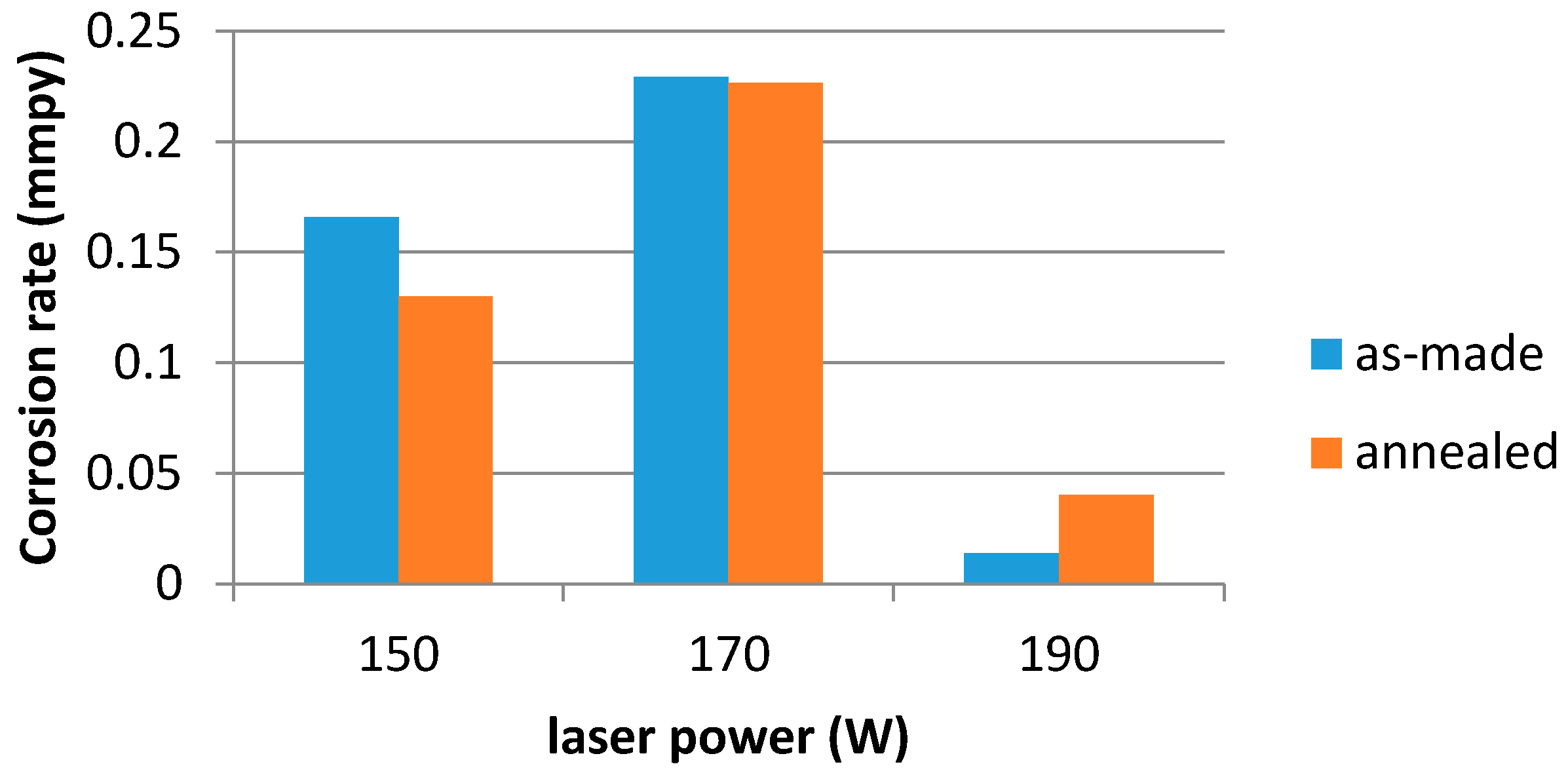
Corrosion rate of materials after 144 h exposure in the test solution, depending on the laser power and heat treatment, is provided in
Figure 10.
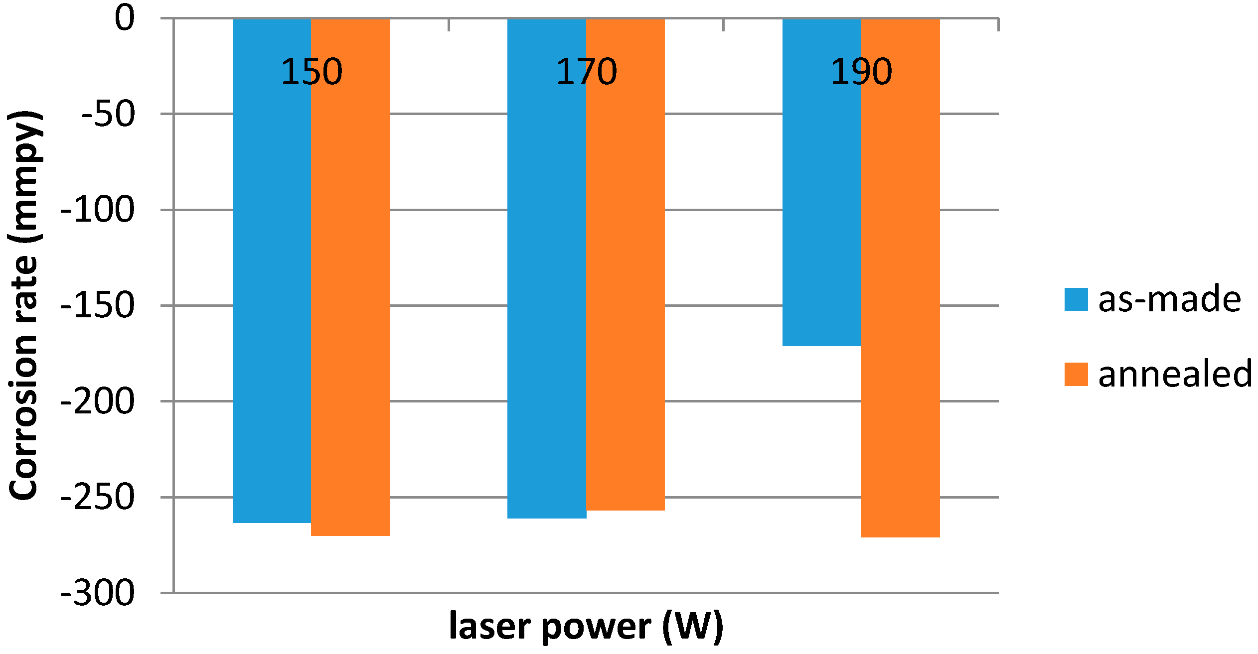
Figure 10 indicates that the laser power effects the corrosion rate of the material. The lowest corrosion rate was recorded at maximum laser power (190 W). Heat treatment does not effect the corrosion rate remarkably, however it leads to stabilization of corrosion potential of materials Ecorr,
Figure 11.
All corrosion parameters are listed in
Table 4.
Considering the measured values of corrosion rate, laser power 190 W can be recommended for implant sintering. However, for determining the suitability of production technology parameters, it is necessary to consider all properties of the material.
With respect to acceptance of the material by the human body, requirements for the surface roughness of the implants can vary. Therefore, experiments aimed at surface morphology modification by blasting were carried out. There were used two types of abrasives of different material and shape and three values of air pressure for blasting. The values of the roughness parameters measured on the material as-made and on materials blasted at different air pressures are shown in
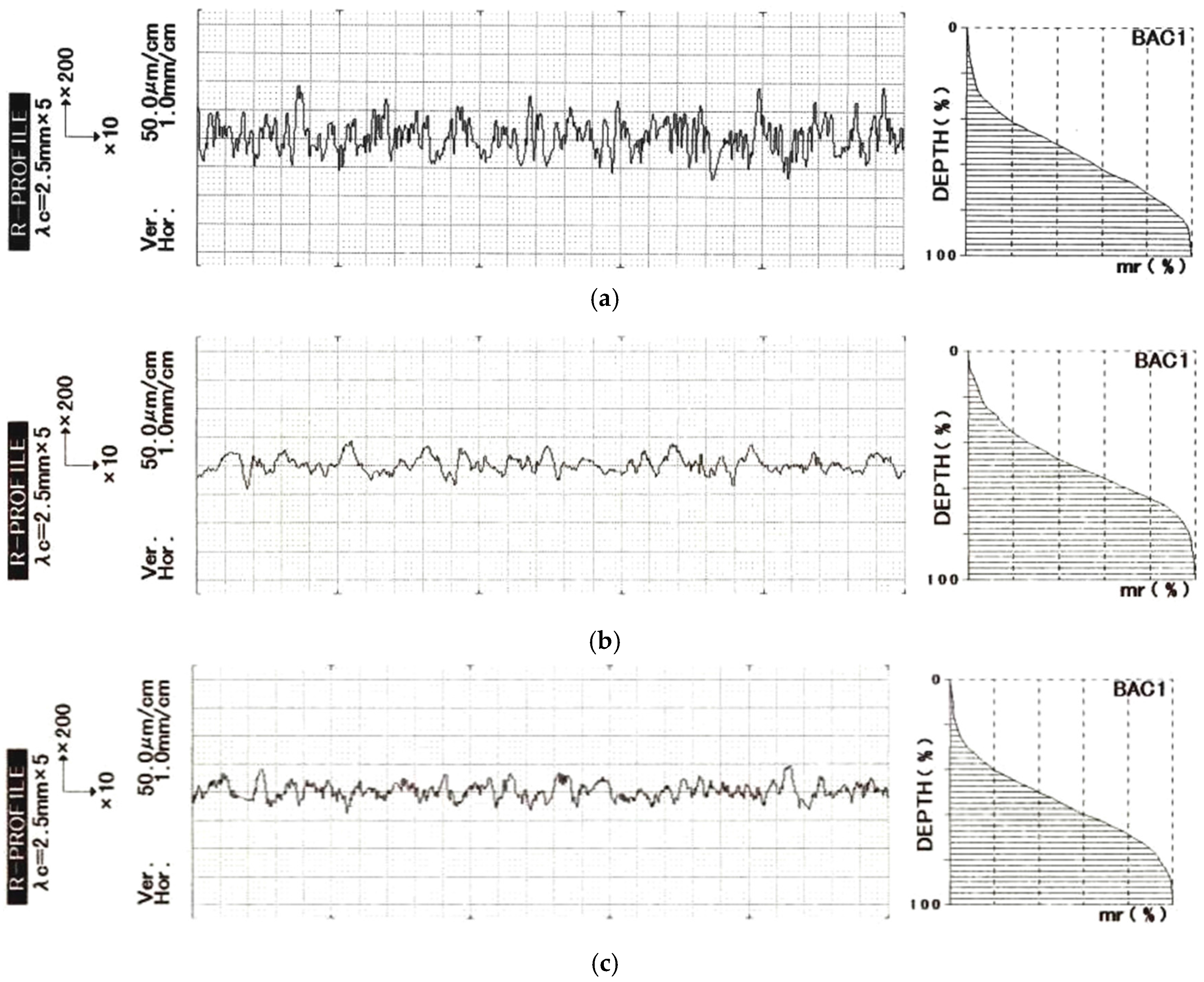
Table 5. Change of surface character is clear from profiles and Abbot-Firestone curve,
Figure 12.
The results of blasting with Zirblast showed that increasing the air pressure lead to decreasing of Ra. This result can be attributed to the ratio of hardness of Ti6Al4V vs. Zirblast. When comparing the parameters Rz and Rt it was shown their gradual decrease. Surface roughness in horizontal direction was characterized by parameters RSm and RPc. There was recorded increasing of RSm parameter at all air pressures by more than 100%, the value of the parameter RPc analogically decreased.
The group of sharp-edged blasting abrasives was represented by white corundum. The values of the parameters Ra, Rz, and Rt decreased with air pressure increasing, but reached higher values compared to surface blasted with Zirblast. The RSm value increased compared to as-made material by 85% and the value of RPc parameter decreased by 100%. For both abrasives, despite their shape and material difference, a similar course of roughness parameters was recorded, but the values were higher for white corundum. Recommendation of appropriate blasting parameters and abrasives depends on the specific demands on the implant surface.
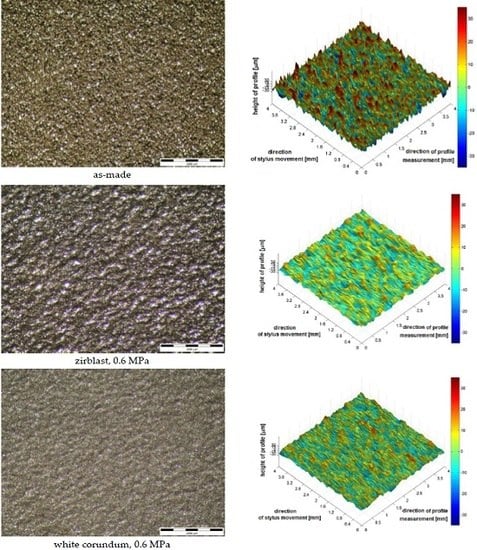
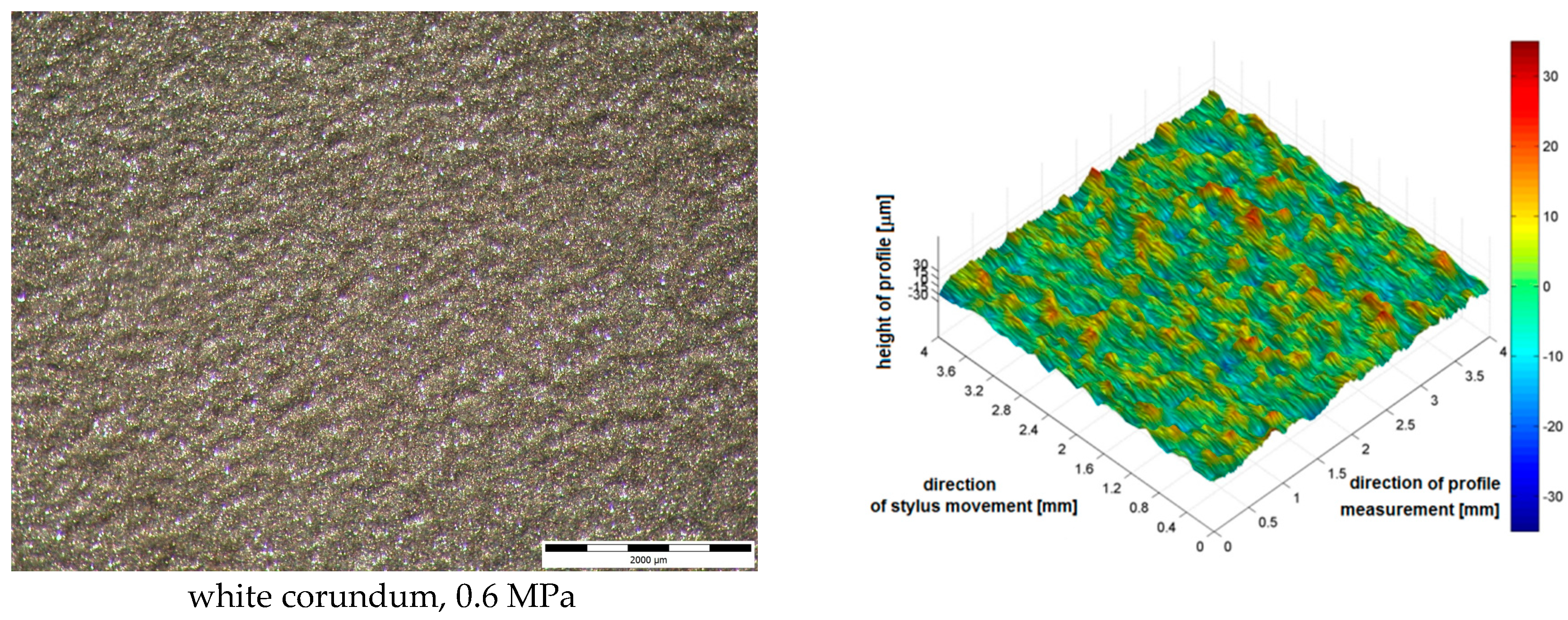
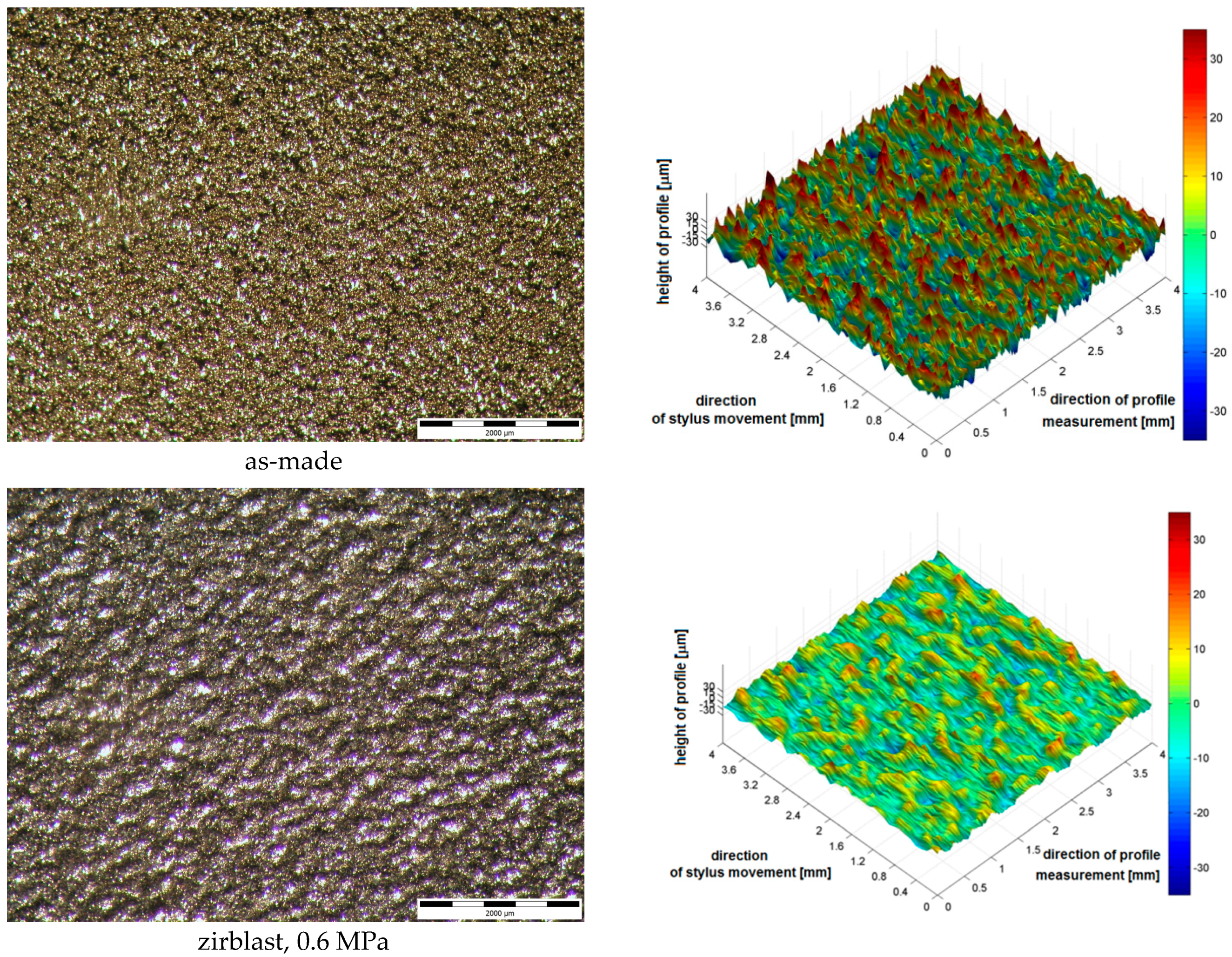
Blasted surfaces were visualized using 3D maps and optical microscopy,
Figure 13. 3D image of surfaces clearly showed the influence of blasting abrasives used to the final character of the surface. Surfaces blasted with spherical abrasive—Zirblast—are characterized by mutually intersecting indentations of spherical cap shape. Surfaces blasted with white corundum consist of large number of sharp notches.
Surface volume (
Vp) of evaluated surfaces is shown in
Table 6. The results showed that the
Vp is higher in surfaces blasted with corundum. It confirms the assumption that the surface is more rugged when blasting with sharp-edged abrasive. These values correspond with results of surface roughness mentioned above. Increasing air pressure led to smoothing surface and lower surface volume.
In
Table 7, we present the calculated
p-values for the individual parameters measured on the samples which have been blasted with two blasting media. For the
Ra,
Rz, and
Rt is a statistical difference in both blasting media. It means that the pressure effects the value of the parameter. For parameters
RSm and
RPc the sample blasted by Zirblast the difference is not statistically significant (pressure does not affect the value of the parameter) for the sample blasted white corundum difference is not statistically significant only for α = 0.01.
The average values of the Zirblast blasted and blasted by white aluminum oxide were compared using the
t-test. The results of
p-values at different pressure are depicted in the
Table 8. At a working pressure of 2 bar, the difference is statistically significant. It means that the type of blasting media has an effect on the value of the parameter. At an operating pressure of 6 bars and 4, it is not statistically significant difference only for the
Ra parameter (type of blasting media has no influence on the value of parameter). Therefore, the type of the blasting media has an influence on characteristics of profile roughness, in particular to its parameters.
Acknowledgments
This work was supported by scientific grant agency of the Ministry of Education of the Slovak Republic VEGA No. 1/0600/13. The authors are grateful to the CEIT-KE, Ltd. in Košice, Slovak Republic for using of their laboratory facilities for experiments.
Author Contributions
Metallography analysis, hardness testing—J.B., A.G.; production and thermal treatment of test samples—R.H.; analysis of surface roughness—D.D.; statistical analysis of measured data—G.I.; measurement of corrosion rate—J.K.
Conflicts of Interest
The authors declare no conflict of interest.
References
- Elias, C.N.; Lima, J.H.C.; Valiev, R.; Meyers, M.A. Biomedical applications of titanium and its alloys. JOM 2008, 60, 46–49. [Google Scholar] [CrossRef]
- Mrázová, M.; Pilc, J. Research of titanium materials in medicine. Acta Tech. Corviniensis Bull. Eng. Fasc. 2012, 2, 85–86. [Google Scholar]
- Niinomi, M.; Nakai, M. Titanium-based biomaterials for preventing stress shielding between implant devices and bone. Int. J. Biomater. 2011, 1–10. [Google Scholar] [CrossRef] [PubMed]
- Schnitzer, M.; Lisý, M.; Hudák, R.; Živčák, J. Experimental measuring of the roughness of test samples made using DMLS technology from the Titanium alloy Ti-6Al-4V. In Proceedings of the SAMI 2015: IEEE 13th International Symposium on Applied Machine Intelligence and Informatics, Herlany, Slovakia, 22–24 January 2015; pp. 31–36.
- Maya-Johnson, S.; López, D. Effect of the cooling rate in the corrosion behavior of a hot worked Ti-6Al-4V extra-low interstitial alloy. Mater. Des. 2014, 58, 175–181. [Google Scholar] [CrossRef]
- Pavón, J.; Jiménez-Piqué, E.; Anglada, M.; López-Esteban, S.; Saiz, E.; Tomsia, A.P. Stress-corrosion cracking by indentation techniques of a glass coating on Ti6Al4V for biomedical applications. J. Eur. Ceram. Soc. 2006, 26, 1159–1169. [Google Scholar] [CrossRef]
- Bărbînţă, A.C.; Chelariu, R.; Crimu, C.I.; Istrate, B.; Nazarie, S.; Earar, K.; Munteanu, C. Metallographic characterization of a new biomedical titanium-based alloy for orthopedic applications. Bull. Transilv. Univ. Braşov Ser. I Eng. Sci. 2013, 6, 86–88. [Google Scholar]
- Moravec, H.; Fojt, J.; Filip, V.; Joska, L. Modifikace povrchu titanu pro medicínské aplikace. Chem. Listy 2014, 108, 40–45. [Google Scholar]
- Joshi, V.A. Titanium Alloys: An Atlas of Structures and Fracture Features; CRC Press: Boca Raton, FL, USA, 2006; p. 248. [Google Scholar]
- Svoboda, E.; Bartošík, P.; Dvořáková, R.; Tran, Q.D. Influence of the measurement conditions on the surface roughness parameters. Hutn. Listy 2011, 64, 56–63. [Google Scholar]
- Ali, S.H.R. Advanced nanomeasuring techniques for surface characterization, review article. Int. Sch. Res. Netw. ISRN Opt. 2012, 1–23. [Google Scholar] [CrossRef]
- Draganovská, D.; Ižaríková, G.; Brezinová, J.; Guzanová, A. The study of parameters of surface roughness by the correlation analysis. Mater. Sci. Forum 2015, 818, 15–18. [Google Scholar] [CrossRef]
- Brezinová, J.; Guzanová, A.; Draganovská, D. Abrasive Blast Cleaning and Its Application; Trans Tech Publications: Pfaffikon, Switzerland, 2015; p. 107. [Google Scholar]
- Yadroitsev, I.; Krakhmalev, P.; Yadroitsava, I. Selective laser melting of Ti6Al4V alloy for biomedical applications: Temperature monitoring and microstructural evolution. J. Alloy. Compd. 2014, 583, 404–409. [Google Scholar] [CrossRef]
- Song, B.; Dong, S.; Liao, H.; Coddet, C. Process parameter selection for selective laser melting of Ti6Al4V based on temperature distribution simulation and experimental sintering. Int. J. Adv. Manuf. Technol. 2012, 61, 967–974. [Google Scholar] [CrossRef]
- Hudák, R.; Šarik, M.; Dadej, R.; Živčák, J.; Harachová, D. Material and thermal analysis of laser sintered products. Acta Mech. Automat. 2013, 7, 15–19. [Google Scholar]
- Pyka, G.; Kerckhofs, G.; Papantoniou, I.; Speirs, M.; Schrooten, J.; Wevers, M. Surface roughness and morphology customization of additive manufactured open porous Ti6Al4V structures. Materials 2013, 6, 4737–4757. [Google Scholar] [CrossRef]
- Ivanov, M.B.; Manokhin, S.S.; Kolobov, Y.R.; Nechayenko, D.A. Phase composition and microstructure of Ti-6Al-4V alloy after hydrogen-plastic working. Mater. Phys. Mech. 2010, 10, 62–71. [Google Scholar]
- Qiu, C.; Adkins, N.J.E.; Attallah, M.M. Microstructure and tensile properties of selectively laser-melted and of HIPed laser-melted Ti-6Al-4V. Mater. Sci. Eng. A 2013, 578, 230–239. [Google Scholar] [CrossRef]
- Wang, J.H.; Cheng, J.; Li, Y.X.; Bai, P.K. Influence of laser scan speed on density and mechanical properties of a Ti6Al4V part produced by means of selective Laser Melting (SLM). Lasers Eng. 2012, 23, 395–401. [Google Scholar]
- Živčák, J.; Hudák, R.; Dadej, R. Výroba implantátov pomocou metódy Rapid Prototyping. Transf. Inov. 2013, 15, 24–30. [Google Scholar]
- Bertol, L.S.; Júnior, W.K.; da Silva, F.P.; Aumund-Kopp, C. Medical design: Direct metal laser sintering of Ti-6Al-4V. Mater. Des. 2010, 31, 3982–3988. [Google Scholar] [CrossRef]
- Ning, Y. Process Parameter Optimization for Direct Metal Laser Sintering (DMLS). Ph.D. Thesis, National University of Singapore, Singapore, 2005. [Google Scholar]
- Custompart.net—Direct Metal Laser Sintering. Available online: http://www.custompartnet.com/wu/direct-metal-laser-sintering (accessed on 10 April 2015).
Figure 1.
The influence of sintering parameters on final properties of material in DMLS technology [
23].
Figure 2.
Scheme of DMLS technology [
24].
Figure 3.
Way of material collection for metallographic observation.
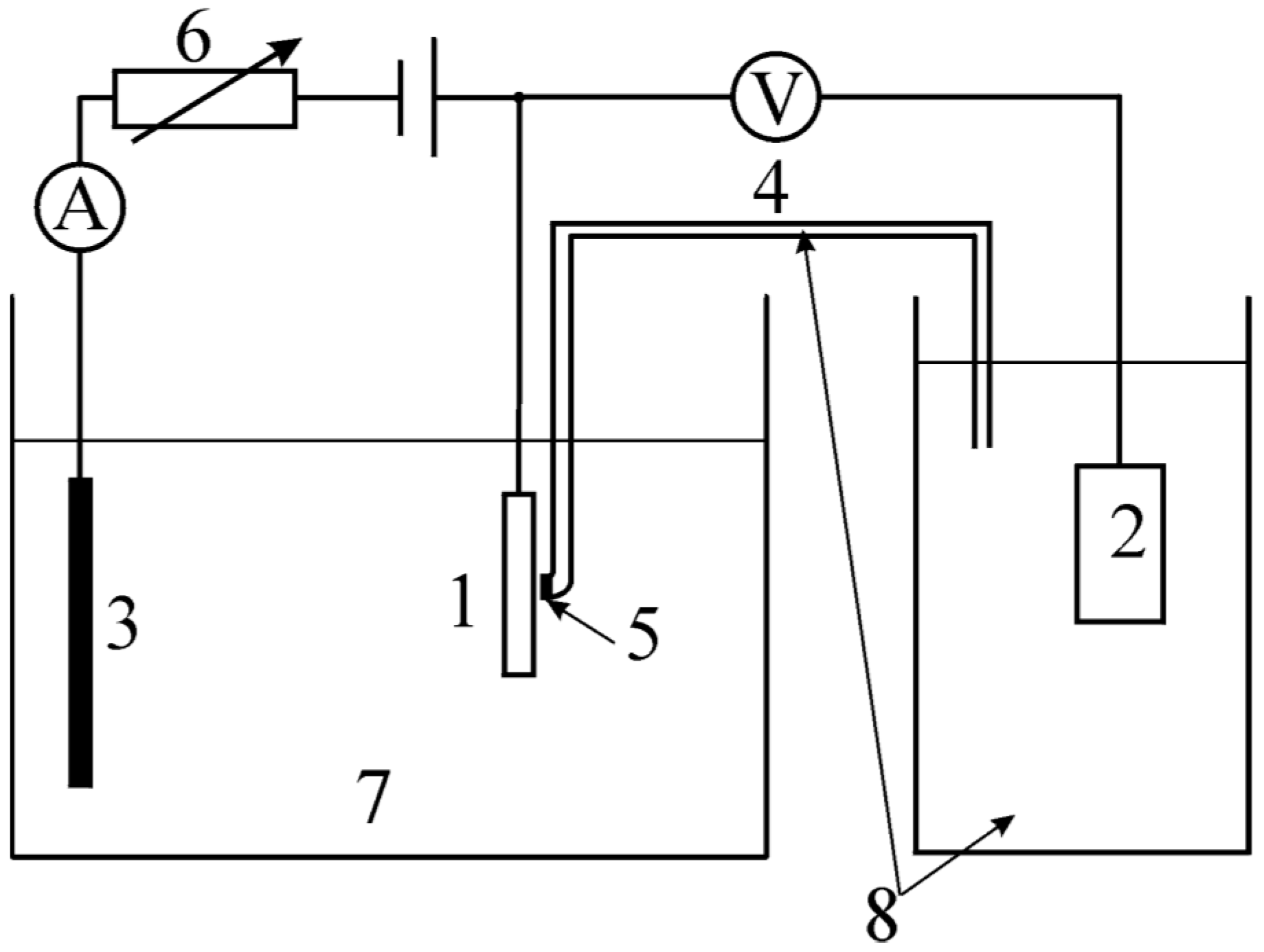
Figure 4.
Three electrode system: 1—working electrode; 2—reference electrode; 3—auxiliary electrode; 4—salt bridge; 5—semipermeable membrane; 6—adjustable voltage source; 7—electrolyte; 8—solution of own ions of reference electrode.
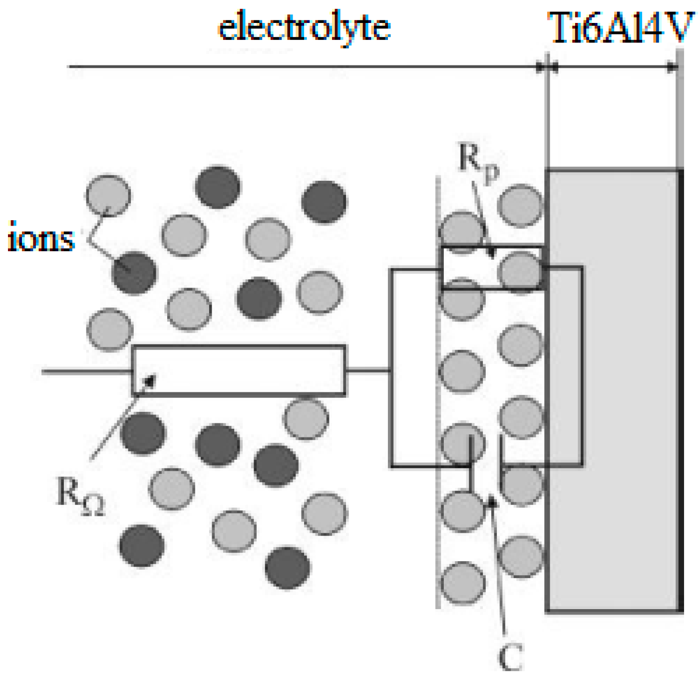
Figure 5.
Interpretation of equivalent circuit for a simple corrosion system.
Figure 6.
Microstructure of sintered materials, 50× mag., LM.
Figure 7.
Microstructure of sintered materials, mag. 500×, LM.
Figure 8.
Microstructure of annealed materials, mag. 500×, LM.
Figure 9.
Hardness of materials depending on the laser power and the direction. (a) Perpendicular to deposited layers; (b) parallel with deposited layers.
Figure 10.
Corrosion rate after 144 h exposure in the test solution.
Figure 11.
Corrosion potential Ecorr after 144 h exposure in the test solution.
Figure 12.
Profiles of materials as-made and blasted. (a) as-made; (b) Zirblast, 0.6 MPa; (c) White corundum, 0.6 MPa.
Figure 13.
3D maps and macro views on evaluated surfaces.
Table 1.
Chemical composition of powder used (wt. %).
| Al | V | Fe | O | N | H | C | Ti |
|---|
| 5.75–6.75 | 3.5–4.5 | max. 0.25 | max. 0.20 | max. 0.05 | max. 0.015 | max. 0.08 | balance |
Table 2.
Chemical composition of abrasives in wt. %.
| Abrasive | Al2O3 | ZrO2 | SiO2 | Fe2O3 | TiO2 | CaO | Na2O | Others |
|---|
| Zirblast | - | 67 | 30 | - | - | - | - | <3 |
| White corundum | >99.6 | - | <0.03 | <0.04 | <0.01 | <0.01 | <0.20 | <0.2 |
Table 3.
Physical properties of abrasives.
| Property | Zirblast | White Corundum |
|---|
| Grain size | 0.125–0.250 mm | 0.09–0.125 mm |
| Shape/Colour | spherical/white | Sharp-edged/white |
| Hardness | 8 Mohs | 9 Mohs |
| Density | 3.85 kg·dm−3 | 3.9 kg·dm−3 |
Table 4.
Corrosion parameters of investigated materials.
| Laser Power (W) | Treatment | Immersion Time (h) | Ecorr (mV vs. SCE) | Icorr (µA) | Beta c (mV) | Beta a (mV) | Rcorr (mmpy) |
|---|
| 150 | sintered | 0 | −288.8 | 0.31 | 141.1 | 115.3 | 0.02 |
| 144 | −263.4 | 3.03 | 213.3 | 234.3 | 0.16 |
| annealed | 0 | −265.3 | 0.55 | 220.1 | 324.4 | 0.03 |
| 144 | −270.1 | 2.38 | 192.2 | 227.6 | 0.13 |
| 170 | sintered | 0 | −220.9 | 0.02 | 48.9 | 36.7 | 0.94 |
| 144 | −260.9 | 4.20 | 215.1 | 231.5 | 0.23 |
| annealed | 0 | −217.0 | 0.02 | 11.0 | 15.0 | 0.75 |
| 144 | −256.7 | 4.14 | 197.2 | 284.9 | 0.23 |
| 190 | sintered | 0 | −337.8 | 0.56 | 253.5 | 70.6 | 0.03 |
| 144 | −171.1 | 0.25 | 82.8 | 518.2 | 0.01 |
| annealed | 0 | −416.0 | 5.00 | 514.0 | 208.9 | 0.24 |
| 144 | −270.9 | 0.74 | 117.6 | 299.7 | 0.04 |
Table 5.
Average values of the roughness parameters.
| Surface | Roughness Parameters |
|---|
| Ra (μm) | Rz (μm) | Rt (μm) | RSm (μm) | RPc (cm−1) |
|---|
| As-made | 11.44 | 65.51 | 70.65 | 216.94 | 47.24 |
| Blasted with Zirblast | 0.2 MPa | 6.24 | 37.96 | 42.23 | 458.87 | 22.65 |
| 0.4 MPa | 5.74 | 35.91 | 41.11 | 476.37 | 22.08 |
| 0.6 MPa | 4.93 | 29.35 | 32.59 | 469.09 | 21.93 |
| Blasted with white corundum | 0.2 MPa | 7.35 | 45.99 | 52.15 | 397.57 | 26.17 |
| 0.4 MPa | 6.02 | 37.88 | 41.91 | 396.44 | 25.90 |
| 0.6 MPa | 5.14 | 32.86 | 35.99 | 360.58 | 28.51 |
Table 6.
Surface volume of evaluated surfaces (108 µm3).
| As-Made | Blasted with Zirblast | Blasted with White Corundum |
| 8.32 | 0.2 MPa | 5.93 | 0.2 MPa | 6.69 |
| 0.4 MPa | 4.38 | 0.4 MPa | 4.93 |
| 0.6 MPa | 3.89 | 0.6 MPa | 3.96 |
Table 7.
p-Values for the individual parameter.
| Roughness Parameters | Zirblast | White Corundum |
|---|
| Ra | 6.36 × 10⁻¹³ p < α | 5.56 × 10⁻²⁷ p < α |
| Rz | 1.29 × 10⁻¹⁶ p < α | 1.21 × 10⁻²⁶ p < α |
| Rt | 1.86 × 10⁻¹⁴ p < α | 1.51 × 10⁻²⁴ p < α |
| RSm | 0.7255 p > α | 0.0403 p < α |
| RPc | 0.7229 p > α | 0.0323 p < α |
Table 8.
p-Values at different pressure.
| Roughness Parameter | Pressure 2 bar | Pressure 4 bar | Pressure 6 bar |
|---|
| Ra | 2.78 × 10−09 p < α | 0.0818 p > α | 0.1239 p > α |
| Rz | 1.84 × 10⁻¹¹ p < α | 0.0354 p < α | 1.68 × 10−05 p < α |
| Rt | 2.09 × 10⁻¹⁰ p < α | 0.04948 p > α | 0.0011 p < α |
| RSm | 0.0031 p < α | 0.0003 p < α | 1.07 × 10−08 p < α |
| RPc | 0.0011 p < α | 0.0003 p < α | 5.96 × 10−09 p < α |
© 2016 by the authors; licensee MDPI, Basel, Switzerland. This article is an open access article distributed under the terms and conditions of the Creative Commons Attribution (CC-BY) license (http://creativecommons.org/licenses/by/4.0/).


