
Low Cycle Fatigue Behaviors of Alloy 617 (INCONEL 617) Weldments for High Temperature Applications


Abstract
: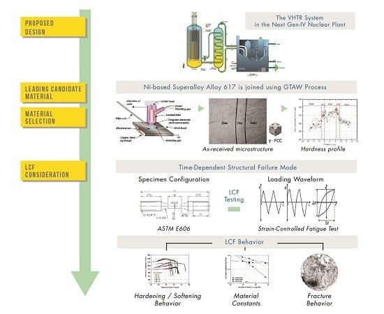
1. Introduction
2. Materials and Methods
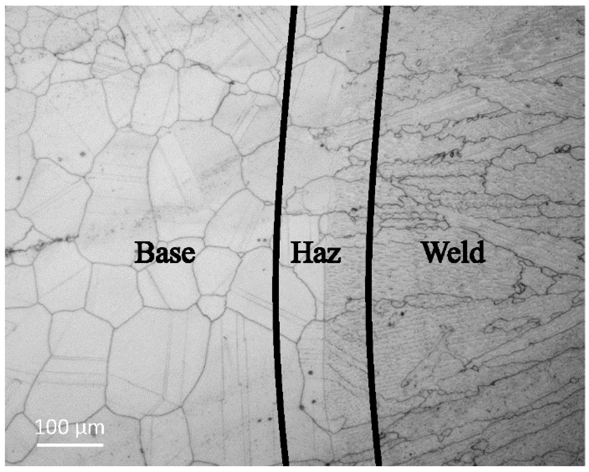
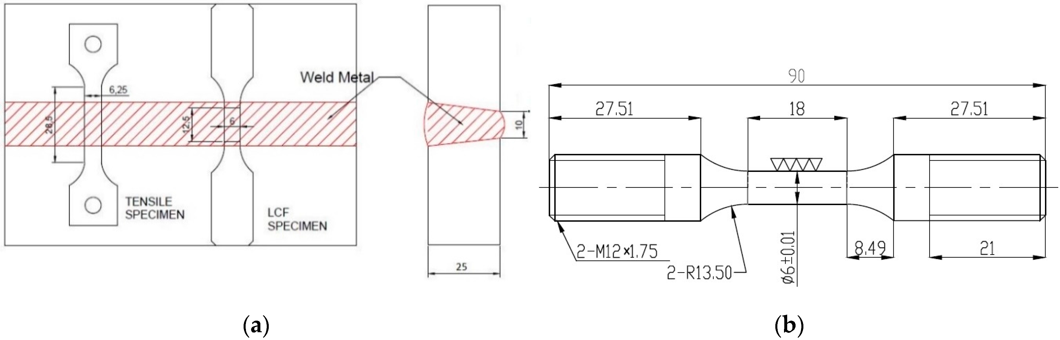
2.1. As-Received Alloy 617 Weldments
2.2. Experimental Methods
3. Results and Discussion
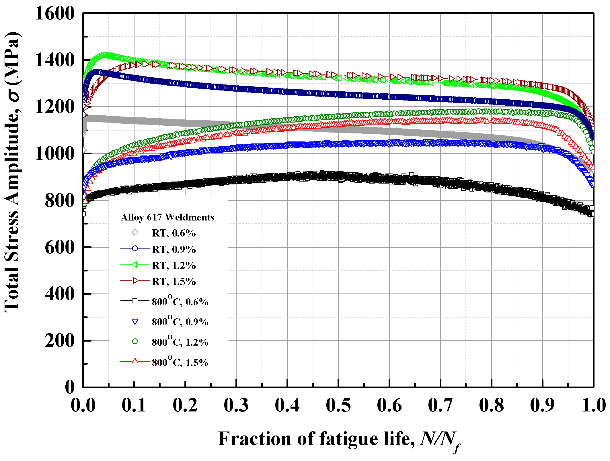
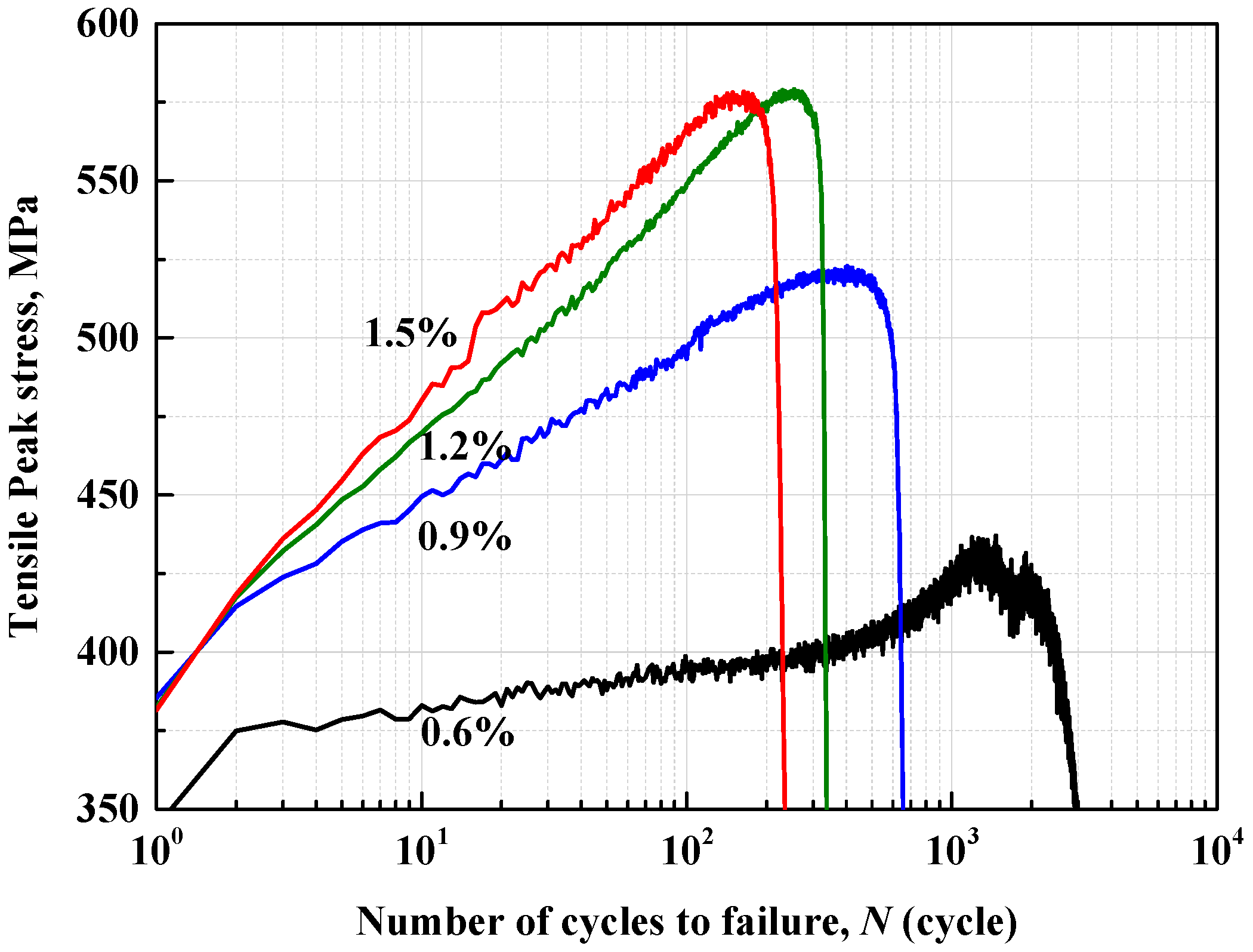
3.1. Low Cycle Fatigue Behaviors of Alloy 617 Weldments
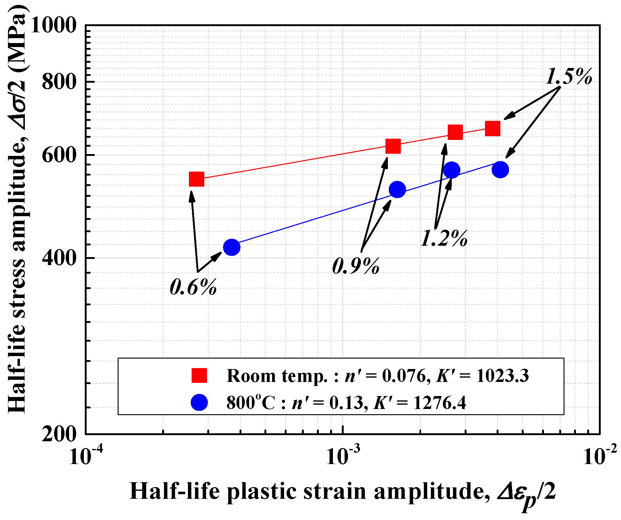
3.2. Low Cycle Fatigue Life Prediction
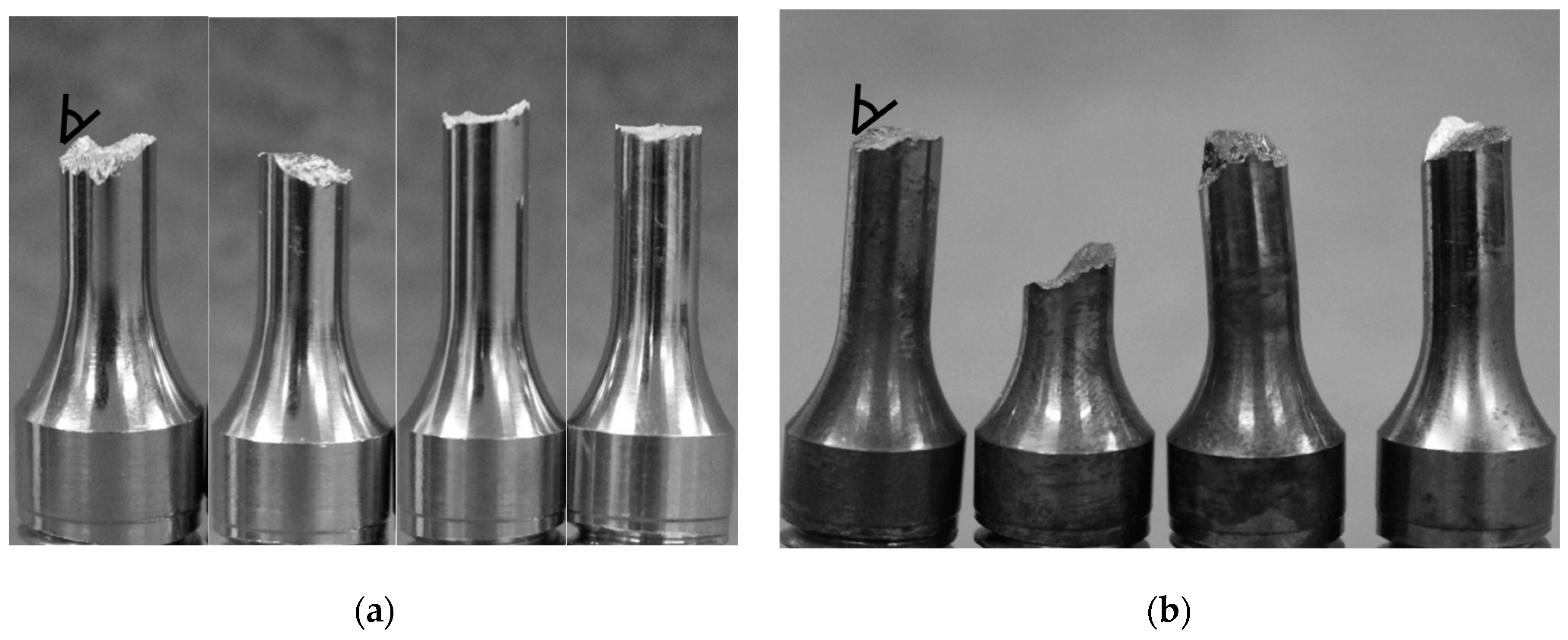
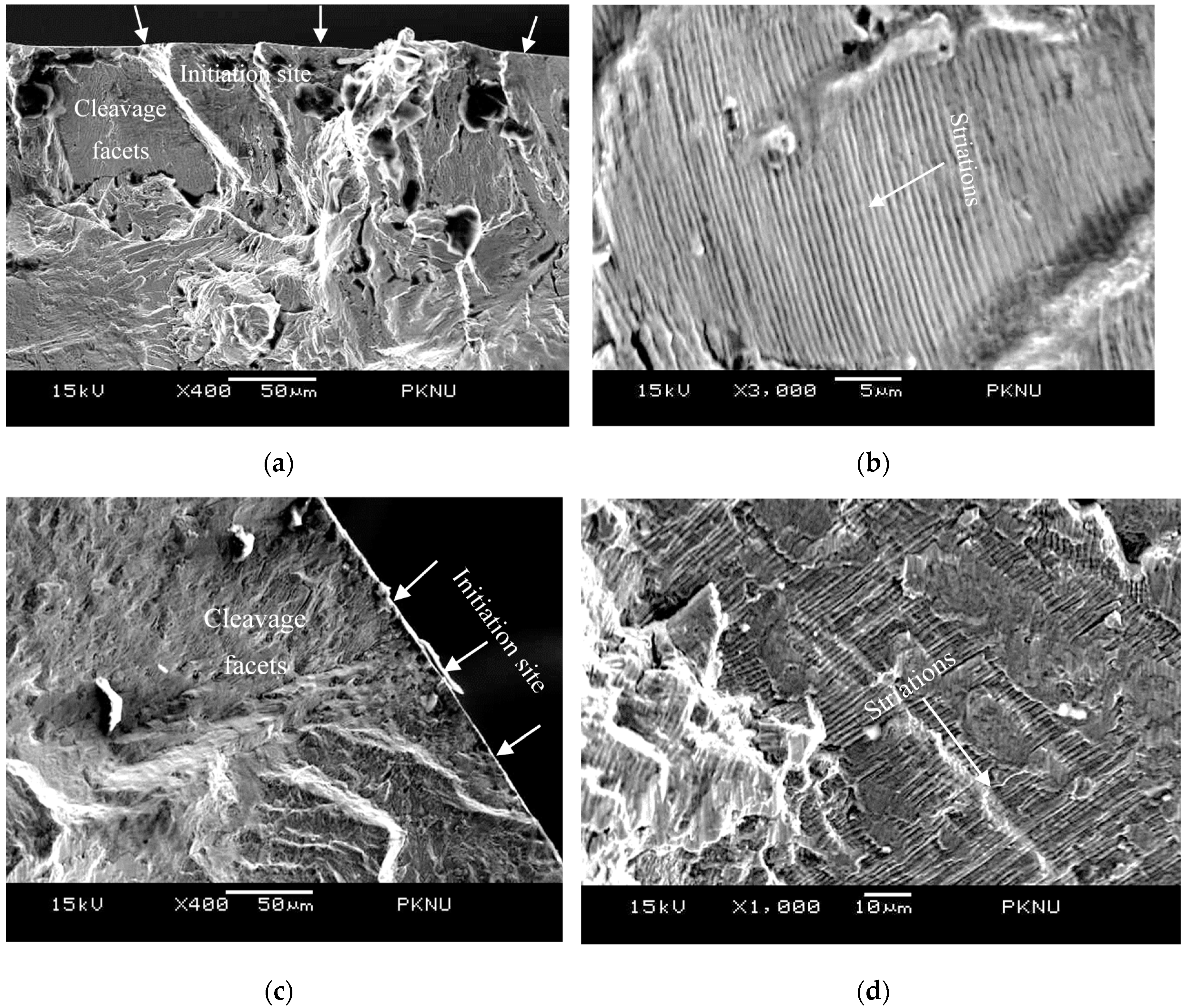
3.3. Fracture Morphologies of Alloy 617 Weldments
4. Conclusions
- The increasing of strain ranges and temperature condition resulted in a reduction of fatigue life. From the results, we can deduce that the higher plastic strain deformation and the material ductility of the 800 °C testing conditions have a major role in the shorter fatigue life.
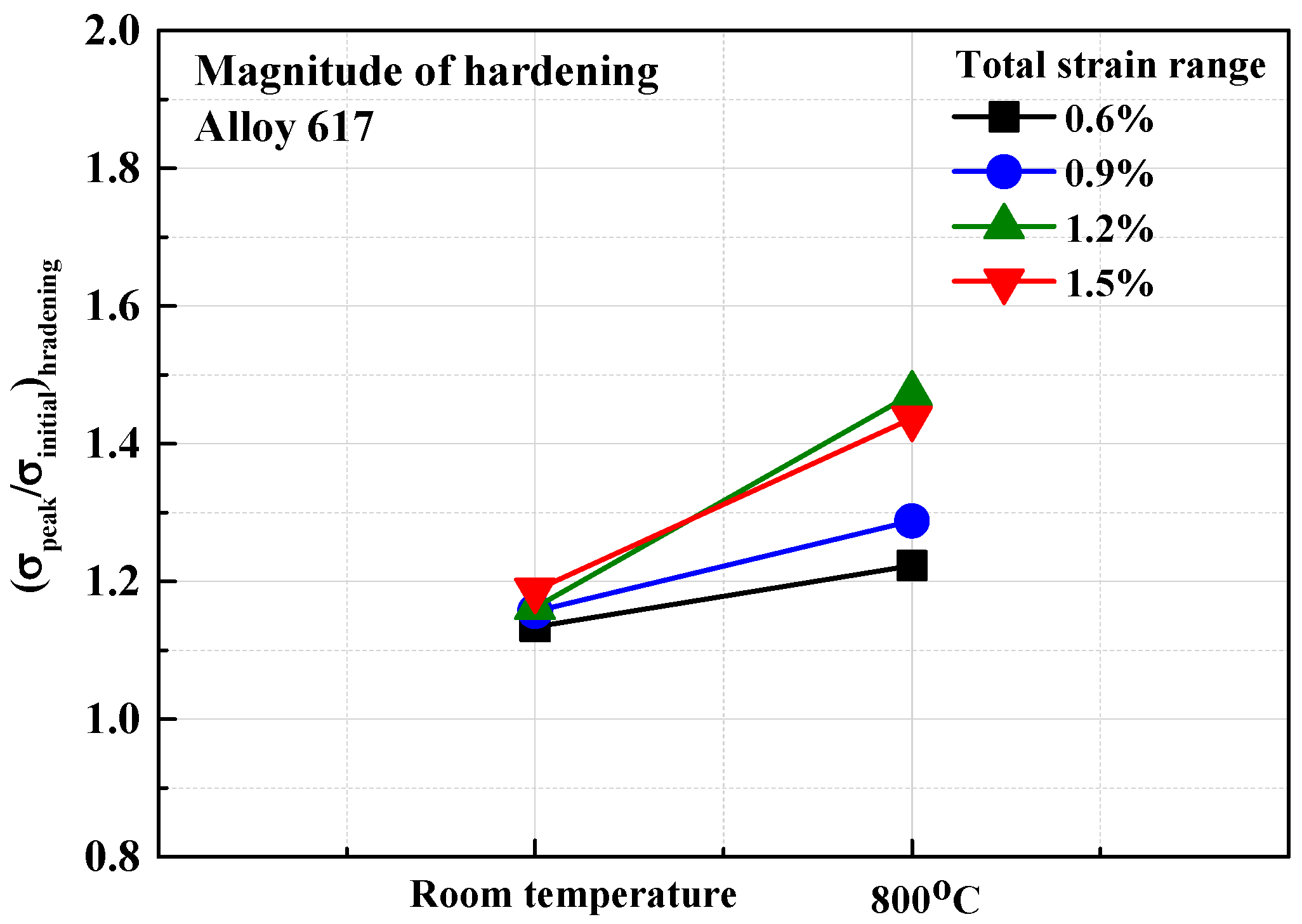
- For room temperature conditions, initial hardening was observed below 200 cycles, after that softening was observed until failure. Meanwhile, the 800 °C condition distinctly showed a cyclic hardening for the major portion of the fatigue life. In the 800 °C condition, we synchronously noticed the serrated flows on the tension-compression stresses at all testing conditions as dynamic strain aging (DSA) phenomena. Since the DSA-induced work hardening process due to atoms interactions may cause the rapid crack propagation, the fatigue life will also decrease in the regime of DSA.
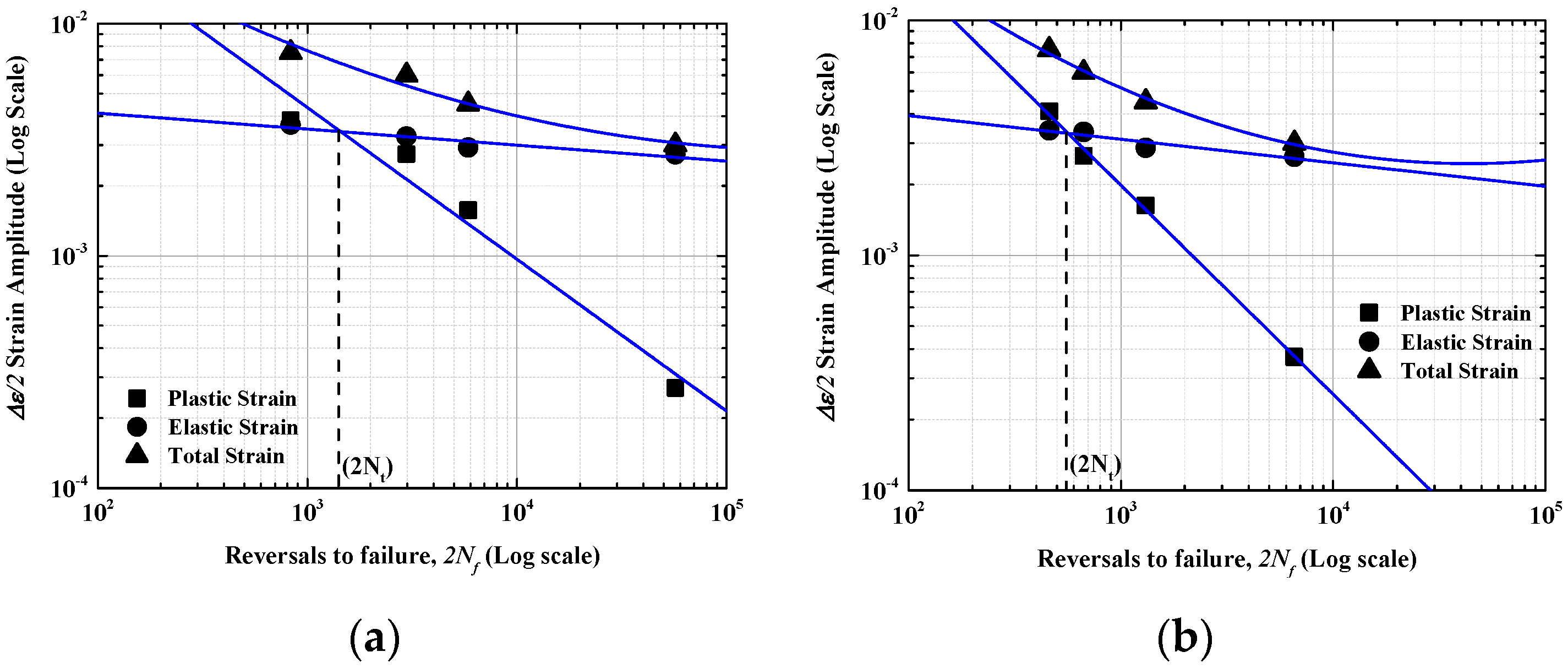
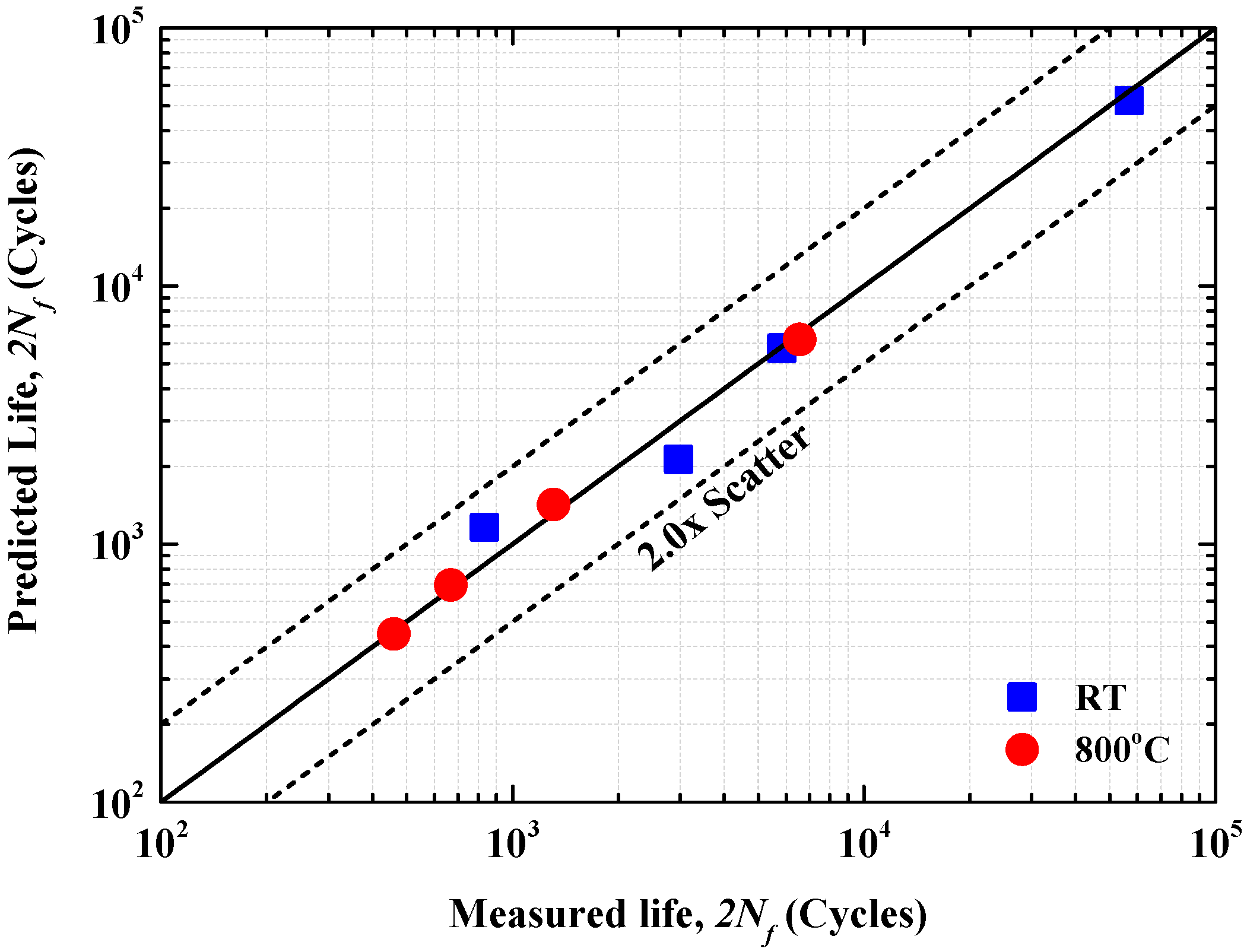
- The observed LCF life was well characterized by the Coffin-Manson relationship, and they are well compared with previous works. The parameter of c slope typically varied from −0.5~−1.0, and, in this study, the c slope was obtained by −0.654 and −0.889 at room temperature and 800 °C conditions, respectively.
- The LCF cracking in weldments occurred inside of the gauge section in the WM region, and showed a wedge-type crack with some deviations oriented at 45° to the loading direction. A transgranular crack initiation with some cleavage facets (stage I) and propagation with some striations (stage II) along with the interdendritic paths were observed.
Acknowledgments
Author Contributions
Conflicts of Interest
References
- Kim, W.G.; Park, J.Y.; Ekaputra, I.M.W.; Kim, S.J.; Kim, M.H.; Kim, Y.W. Creep deformation and rupture behavior of Alloy 617. Eng. Fail. Anal. 2015, 58, 441–451. [Google Scholar] [CrossRef]
- Kim, W.G.; Yin, S.N.; Kim, Y.W.; Ryu, W.S. Creep behaviour and long-term creep life extrapolation of alloy 617 for a very high temperature gas-cooled reactor. Trans. Indian Inst. Met. 2010, 63, 145–150. [Google Scholar] [CrossRef]
- Wright, J.K.; Carroll, L.J.; Wright, R.N. Creep and Creep-Fatigue of Alloy 617 Weldments; Annual Report Idaho National Laboratory: Fremont, CA, USA, August 2014. [Google Scholar]
- Kim, S.J.; Dewa, R.T.; Kim, W.G.; Kim, M.H. Cyclic Stress Response and fracture behaviors of Alloy 617 base metal and weldments under LCF loading. Adv. Mater. Sci. Eng. 2015, 2015. [Google Scholar] [CrossRef]
- Kim, S.J.; Choi, P.H.; Dewa, R.T.; Kim, W.G.; Kim, M.H. Low cycle fatigue properties of Alloy 617 base metal and weldment at room temperature. Proc. Mater. Sci. Eur. Conf. Fract. 2014, 3, 2201–2206. [Google Scholar]
- Prasad Reddy, G.V.; Sandhya, R.; Valsan, M.; Bhanu Sankara Rao, K. High temperature low cycle fatigue properties of 316(N) weld metal and 316L(N)/316(N) weldments. Int. J. Fatigue 2008, 30, 538–546. [Google Scholar] [CrossRef]
- Bhanu Sankara Rao, K.; Schiffers, H.; Schuster, H.; Nickel, H. Influence of time and temperature dependent processes on strain controlled LCF behavior of Alloy 617. Metall. Trans. A 1988, 19A, 359–371. [Google Scholar]
- Meurer, H.P.; Gnirss, G.K.H.; Mergler, W.; Raule, G.; Schuster, H.; Ullrich, G. Investigations on the fatigue behavior of high temperature gas cooled reactor components. Nucl. Technol. 1984, 66, 315–323. [Google Scholar]
- Totemeier, T.C.; Tian, H. Creep-fatigue interactions in INCONEL 617. Mater. Sci. Eng. A 2007, 468–470, 81–87. [Google Scholar] [CrossRef]
- Carroll, L.J.; Cabet, C.; Wright, R.N. The role of environment on high temperature creep-fatigue behaviour of Alloy 617. In Proceedings of the ASME 2010 Pressure Vessel and Piping Division Conference, Bellevue, WA, USA, 18–22 July 2010; pp. 907–916.
- Wright, J.K.; Carroll, L.J.; Simpson, J.A.; Wright, R.N. Low cycle fatigue of Alloy 617 at 850 °C and 950°C. J. Eng. Mater. Technol. ASME 2013, 135, 1–8. [Google Scholar] [CrossRef]
- Chen, X.; Sokolov, M.A.; Sham, S.; Erdman, D.L.; Busby, J.T.; Mo, K.; Stubbins, J.F. Experimental and modeling results of creep-fatigue life of Inconel 617 and Haynes 230 at 850 °C. J. Nucl. Mater. 2013, 432, 94–101. [Google Scholar] [CrossRef]
- Kewther Ali, M.; Hashmi, M.S.J.; Yilbas, B.S. Fatigue properties of the refurbished INCO-617 Alloy. J. Mater. Process. Technol. 2001, 118, 45–49. [Google Scholar] [CrossRef]
- Totemeier, T.C. High-temperature creep-fatigue of Alloy 617 base metal and weldments. In Proceedings of ASME 2007 Pressure Vessels and Piping Conference, San Antonio, TX, USA, 22–26 July 2007; pp. 255–260.
- ASTM E 606-92. Standard Practice for Strain-Controlled Fatigue Testing. In Annual Book of ASTM Standards; ASTM International: Baltimore, MD, USA, 2002; p. 569.
- Hong, J.D.; Lee, J.; Jang, C.; Kim, T.S. Low cycle fatigue behavior of alloy 690 in simulated PWR water—Effects of dynamic strain aging and hydrogen. Mater. Sci. Eng. A 2014, 611, 37–44. [Google Scholar] [CrossRef]
- Gallo, P.; Berto, F.; Lazzarin, P. High temperature fatigue tests of notched specimens made of titanium Grade 2. Theor. Appl. Fract. Mech. 2015, 76, 27–34. [Google Scholar] [CrossRef]
- Louks, R.; Susmel, L. The linear-elastic Theory of Critical Distances to estimate high-cycle fatigue strength of notched metallic materials at elevated temperatures. Fatigue Fract. Eng. Mater. Struct. 2015, 38, 629–940. [Google Scholar] [CrossRef]
- Hong, S.G.; Lee, S.B. Mechanism of dynamic strain aging and characterization of its effect on the low-cycle fatigue behavior in type 316L stainless steel. J. Nucl. Mater. 2005, 340, 307–314. [Google Scholar] [CrossRef]


| C | Ni | Fe | Si | Mn | Co | Cr | Ti | P | S | Mo | Al | B | Cu | ||
|---|---|---|---|---|---|---|---|---|---|---|---|---|---|---|---|
| ASTM Spec | Min | 0.05 | Bal. | - | - | - | 10 | 20 | - | - | - | 8 | 0.8 | - | - |
| Max | 0.15 | Bal. | 3.0 | 1.0 | 1.0 | 15 | 24 | 0.6 | 0.015 | 0.015 | 10 | 1.5 | 0.006 | 0.5 | |
| Alloy 617 | - | 0.08 | 53.11 | 0.95 | 0.08 | 0.03 | 12.3 | 22 | 0.41 | 0.003 | <0.002 | 9.5 | 1.06 | <0.002 | 0.027 |
| Temperature (°C) | YS (MPa) | UTS (MPa) | EL (%) |
|---|---|---|---|
| Room temperature | 462 | 764.9 | 24.6 |
| 800 °C | 314 | 382.7 | 27.3 |
| Specimen Reference | Cycles to Failure | Elastic Strain Amp (mm/mm) | Plastic Strain Amp (mm/mm) | Stress Amp (MPa) | |
|---|---|---|---|---|---|
| Temperature | Total Strain Amp (mm/mm) | ||||
| Room temperature | 0.0075 | 416 | 0.0037 | 0.0038 | 665.9 |
| 0.0060 | 1485 | 0.0033 | 0.0027 | 656.2 | |
| 0.0045 | 2924 | 0.0029 | 0.0016 | 621.1 | |
| 0.0030 | 28422 | 0.0027 | 0.0003 | 545.6 | |
| 800 °C | 0.0075 | 230 | 0.0034 | 0.0041 | 566.3 |
| 0.0060 | 334 | 0.0034 | 0.0026 | 565.3 | |
| 0.0045 | 655 | 0.0029 | 0.0016 | 523.9 | |
| 0.0030 | 3282 | 0.0026 | 0.0004 | 417.2 | |
| Temperature | εf' | c | σf' (MPa) | b | E (GPa) | n‘ | K‘ (MPa) |
|---|---|---|---|---|---|---|---|
| Room temperature | 0.398 | −0.654 | 1213 | −0.104 | 214.4 | 0.118 | 1086.43 |
| 800℃ | 0.924 | −0.889 | 973 | −0.100 | 155.9 | 0.14 | 1276.4 |
| Temperature | 2Nt | Δε/2 |
|---|---|---|
| Room temperature | 1410 | 0.0035 |
| 800℃ | 554 | 0.0033 |
© 2016 by the authors; licensee MDPI, Basel, Switzerland. This article is an open access article distributed under the terms and conditions of the Creative Commons Attribution (CC-BY) license (http://creativecommons.org/licenses/by/4.0/).
Share and Cite
Dewa, R.T.; Kim, S.J.; Kim, W.G.; Kim, E.S. Low Cycle Fatigue Behaviors of Alloy 617 (INCONEL 617) Weldments for High Temperature Applications. Metals 2016, 6, 100. https://doi.org/10.3390/met6050100
Dewa RT, Kim SJ, Kim WG, Kim ES. Low Cycle Fatigue Behaviors of Alloy 617 (INCONEL 617) Weldments for High Temperature Applications. Metals. 2016; 6(5):100. https://doi.org/10.3390/met6050100
Chicago/Turabian StyleDewa, Rando Tungga, Seon Jin Kim, Woo Gon Kim, and Eung Seon Kim. 2016. "Low Cycle Fatigue Behaviors of Alloy 617 (INCONEL 617) Weldments for High Temperature Applications" Metals 6, no. 5: 100. https://doi.org/10.3390/met6050100