Article

Improving Beneficiation of Copper and Iron from Copper Slag by Modifying the Molten Copper Slag

School of Mineral Processing and Bioengineering, Central South University, Changsha 410083, China
*
Authors to whom correspondence should be addressed.
Metals 2016, 6(4), 86; https://doi.org/10.3390/met6040086
Submission received: 26 February 2016 / Revised: 4 April 2016 / Accepted: 7 April 2016 / Published: 14 April 2016

Abstract

:
In the paper, a new technology was developed to improve the beneficiation of copper and iron components from copper slag, by modifying the molten slag to promote the mineralization of valuable minerals and to induce the growth of mineral grains. Various parameters, including binary basicity, dosage of compound additive, modification temperature, cooling rate and the end point temperature of slow cooling were investigated. Meanwhile, optical microscope, scanning electron microscope and energy dispersive spectrometer (SEM-EDS) was employed to determine the mineralogy of the modified and unmodified slag, as well as to reveal the mechanisms of enhancing beneficiation. The results show that under the proper conditions, the copper grade of rougher copper concentrate was increased from 6.43% to 11.04%, iron recovery of magnetic separation was increased significantly from 32.40% to 63.26%, and other evaluation indexes were changed slightly, in comparison with unmodified copper slag. Moreover, matte and magnetite grains in the modified slag aggregated together and grew obviously to the mean size of over 50 μm, resulting in an improvement of beneficiation of copper and iron.

1. Introduction

Pyrometallurgy is the dominant technology for current copper extraction, by which almost 80% of total copper in the word has been generated [1]. Approximately 2.0–3.0 tons of copper slag are generated per ton of copper production, depending on the properties of copper concentrates and operating conditions in the pyrometallurgical process [2,3,4,5]. It has been roughly estimated that approximately 12 million tons of copper slag is produced every year, and the amount of accumulated waster copper slag reached 140 million ton by 2015 in China [6]. Generally, copper slag contains about 35–45 wt. % iron and 0.5–1.5 wt. % copper, indicating that it is a valuable secondary resource for recycling and utilization [3]. However, more than 80% of copper slag has not been effectively utilized, which not only wastes the valuable resources, but also potentially causes severe damages to the ecological environment, such as heavy metal pollution to surrounding soils and watercourses [7,8]. Hence, it is extremely urgent to develop appropriate technology for comprehensive utilization of copper slag characterized as hazardous materials, due to the increasing environmental concern for disposal of copper slag.
In recent years, extensive studies have been carried out to recover the valuable metals from copper slag. Basically, they can be classified into three main categories, namely physical separation process, pyrometallurgical process and hydrometallurgical process, such as flotation [9,10,11,12], roasting [13,14] and leaching [15,16]. Indeed, these are effective routes to recover and utilize the copper and other non-ferrous metals. Particularly, it is considerably successful to recovery copper from slow-cooled copper slag by flotation process. However, these methods may suffer secondary pollutants or a difficulty in further treatments, and the recovery of iron is neglected.
An earlier work noted that magnetic separation is a feasible way to recover iron from the tailings of waste copper slag flotation. Unfortunately, the iron grade of magnetic products and the recovery of iron by the magnetic separation process is relatively low, only 52.21% and 38.09%, respectively, due to the fact that iron constituents mainly exist in the form of fayalite (Fe2SiO4) [17]. Therefore, regarding the recovery of iron from copper flotation slag, more prior works focused mostly on the pyrometallurgical process, such as roasting-magnetic process and smelting reduction process. The roasting-magnetic separation process is the route to convert the metals into a desired phase, which can be easily separated from the slag through mixing copper slag with calcium oxide as fluxes and carbon as a reducing agent, then roasting the mixture at a temperature of about 1200–1300 °C, followed by magnetic separation to recover iron from the copper flotation slag [18,19,20,21,22]. The smelting reduction process is a method where waste slag is carbothermally smelted to acquire molten iron by reducing “FeO” to metallic iron at very high temperatures (above 1350 °C) [23]. However, these processes have some disadvantages such as high temperature, energy consumption and production cost. In brief, it is difficult to recover copper and iron in the slag technically, effectively and economically by traditional separation technologies, and much latent heat is wasted when discharging the molten slag from the furnace at 1250–1300 °C to slowly cool for recovery copper as well as other non-ferrous metals by flotation and heating the tailings again to recover iron. In addition, previous researchers have only focused on cold copper slag when slag-recycling issues are studied; however, once the slag cools down from its molten state to its solidification, the cold slag and its physical properties are often considered to be fixed. Generally, there is a significantly potential to affect the functional properties of the cold slag during the hot stage of slag processing [24]. If the high temperature slag treatment process is applied to molten slag, the properties of slag can be tailored to the requirements of the targeted application.
Herein, an innovative technology has been developed to transform fayalite to magnetite and to induce the grain growth of copper matte and magnetite by modifying the molten copper slag. As a result, it is effective to improve recovery and separation of copper and iron from the copper slag; meanwhile, the latent heat energy of the molten slag was effectively utilized and the energy consumption is also reduced. Therefore, the employment of the new technology promises many significant benefits, such as a reduction in the wastes or recycling byproducts in non-ferrous metallurgy process, and provides solutions for future metal security.

2. Materials and Methods

2.1. Materials

2.1.1. Copper Slag

The copper slag used in the experiments is a byproduct generated during the cleaning of electric furnace slag and refining of copper in Tongling Non-ferrous Metals Group Holding Co., Ltd (Tongling, China). As shown in Table 1, the main chemical compositions contained in the waste slag are 42.85 wt. % FeO and 31.11 wt. % SiO2, and the content of Cu reached 0.80 wt. %. The X-ray diffraction (XRD) spectrum of an average sample is shown in Figure 1, indicating that the main crystal phases in the slag are fayalite (Fe2SiO4) and magnetite (Fe3O4).
Chemical phase analysis of the sample was determined to measure the quantitative distribution characteristic of iron and copper in the copper slag, and the results are illustrated in Table 2 and Table 3, respectively. Iron mainly exists in the form of fayalite and magnetite, which will result in relatively low recovery of iron by traditional magnetic separation process, and copper mainly occurs in the form of copper sulfide and metallic copper, and combined copper oxide fraction is also as high as 17.50%.
Figure 2 presents the micrographs of copper slag, which confirms that fayalite and magnetite are the main minerals in the copper slag, and they are closely combined with copper matte and glassy phase. It is also observed that matte, as the copper-bearing mineral, and magnetite are characterized by super fine particle size of a few micro inclusions being homogeneously dispersed in the slag.

2.1.2. Flux

CaO of analytic grade was used as flux in this work to adjust the binary basicity (ratio of CaO/SiO2) of mixture, and its particle size is less than 74 μm.

2.1.3. Compound Additive

The compound additive containing hematite, sulfide and viscosity reducer was produced by Central South University, in a powder form with over 80% passing 43 μm, and the major chemical constituents as shown in Table 4.

2.2. Experimental Methods

As depicted in Figure 3, the proposed procedure mainly includes the steps of: (1) crushing copper slag; (2) mixing the slag with additives; (3) subjecting the mixture to modification reactions at high temperature and then slowly cooling; (4) recovering copper from the cooled slag obtained in Step 3 by flotation; and (5) separating iron from the tailings of Step 4 by wet magnetic separation.

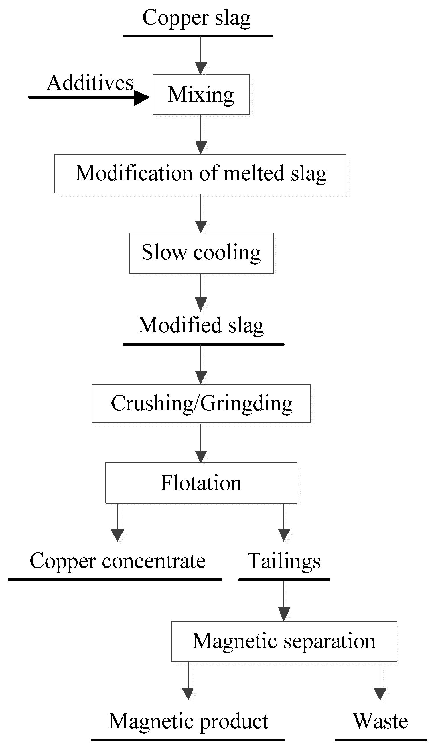
2.2.1. Modification of Copper Slag

The modification and slow cooling of copper slag was conducted in a MoSi2 electric furnace under the high purity N2 (nitrogen) flow of 10 L/min. In the study, the copper slag was crushed to below 0.15 mm by a hammer and a pulverizer. Then, the raw slag was mixed with a certain quantity of additives (burnt lime and compound additive) according to the required amount in alumina crucible. The raw mixture was completely mixed manually for about 15 min. After that, the uniformly mixed raw materials were charged into an electric resistance furnace and were heated up in nitrogen atmosphere. After reaching the target temperature, the furnace was kept at that temperature for 120 min so that the temperature inside the furnace and the slag had enough time to become uniform and constant, and then it was slowly cooled to a certain temperature (end point temperature of slow cooling) at different cooling rates. Once the slow cooling stage was concluded, the samples were taken out of the furnace and cooled to ambient temperature under the protection of nitrogen for the subsequent beneficiation processes.

2.2.2. Flotation and Magnetic Separation

In this research, direct one stage flotation (rougher) and magnetic separation (rougher) has been used. The experimental results were evaluated by modification efficiency and phase transformation degree.
Prior to grinding, the modified copper slag was crushed to a particle size below 1 mm. Then, a 100 g batch of slag (as crushed) was mixed with 100 mL of water and ground in a small stainless steel ball mill (model: XMQ240×90, Wuhan Rock Crush & Grand Equipment Manufacture Co., Wuhan, China). Grind establishment tests determined the time required to produce a P90 of 45 μm. After grinding, flotation experiment was conducted in a 0.5 L RK/FD-60 cell with 2500 rpm impellor speed. Meanwhile, air was delivered to the cell at 8 dm3/min and pulp pH at 9–9.5. In the flotation, the collector and frother used were a commercial sodium butyl xanthate (KBX) and terpineol, respectively. The flotation process involved the addition of KBX (200 g/t, 3 min conditioning), followed by the addition of terpineol (20 g/t, 3 min conditioning), after which flotation concentrates were collected for 5 min.
After flotation, a 30 g batch of dry waste slag (flotation tailings) was subjected to wet magnetic separation using a magnetic field intensity of 0.17 Tesla for 10 min in a Davis Tube (model: XCGS-73, Changsha Research Institute of Mining and Metallurgy Co., Changsha, China). Iron concentrate was produced as product, and the non-magnetic part of the tailings would probably be utilized as a material for cement manufacture.
These dosages of reagent and parameters were fixed based on various previous experiments to achieve a copper and iron recovery in the laboratory.
In order to demonstrate the effect of modification process on the beneficiation of copper and iron, the unmodified copper slag was beneficiated in parallel by floatation-magnetic separation under the same conditions as for modified slag.

2.2.3. Mechanism of Modification

X-ray diffraction (XRD) patterns were recorded by a diffractometer (RIGAKU D/Max 2500, Rigaku Co., Tokyo, Japan). Microstructures of slag were performed by Leica DMLP optical microscopy, FEI Quata-200 scanning electron microscope (FEI Company, GG Eindhoven, The Netherlands) and EDAX32 genesis spectrometer (Ametek Inc., Paoli, CO, USA). Scanning electron microscope (SEM) images were recorded in backscatter electron modes operating in low vacuum mode at 0.5 Torr and 20 keV.

2.3. Evaluation Indexes

The modification results were assessed by the recovery of copper and iron, but copper recovery was the main priority in the present research.
In the flotation process, the yield of copper concentrate and recovery of copper were calculated according to Equations (1) and (2), respectively.
γ = m/m0 × 100%
ε = γ × β/α × 100%
where γ is the yield of cooper concentrate (%); m0 is the feed mass of modified slag subjected to flotation (g); m is the mass of obtained copper concentrate (g); ε is the recovery of copper (%); α is the copper grade in the feed (%); and β is the copper grade in the concentrate (%).
Similarly, the yield of magnetite concentrate and recovery of iron were calculated like Equations (1) and (2), respectively.

3. Results and Discussion

3.1. Thermodynamic Analysis

In the modification process, the calcium oxide and compound additive were added because they help reconstruct the mineral phase of copper slag.
It has been found that calcium oxide can preferentially combine with “SiO2” to form “CaSiO3” and readily replace the “FeO” in the fayalite resulting in an increase in the activity of ‘‘free’’ FeO in the slag [25,26,27,28]. Hence, with more “FeO” released, the Fe2O3 reacted with that to form more Fe3O4, as shown in Equations (3) and (4).
CaO + 2FeO·SiO2 → CaO·SiO2 + 2FeO
FeO + Fe2O3 → Fe3O4
In addition, on account of partial copper presenting as copper oxide and combine copper oxide (as seen in Table 3), the sulfuring treatment of copper slag to recover copper sulfide is necessary by adding compound additive. The most likely sulfuration reactions in the modification process in the presence of compound additive are listed as Equations (5) and (7) [25,27]:
FeS + Cu2O → FeO + Cu2S
GTθ = − 144750 + 13.05T, J/mol
FeS + 3Fe3O4 → 10FeO + SO2
GTθ = 654720 − 381.95T, J/mol
The equilibrium constant for Equation (5) can be calculated at various modification temperatures from 1250 to 1350 °C by Equation (6), and the results are shown in Table 5.
It is inferred from Table 5 that Cu2O (or other oxidized copper, such as CuO and CuO·Fe2O3) is completely sulfurized to Cu2S by FeS readily at modification temperature from the view of thermodynamics as the equilibrium constant is relative high.
At SO2 partial pressure of 10−2 atm, the relationship between aFeS and aFe3O4 in molten slag with different value of aFeO was calculated by Equation (5), and the result is plotted in Figure 4.
As shown in Figure 4, with an increase in aFeS, the aFe3O4 decreases obviously; moreover, increasing temperature tends to inhibit generating of Fe3O4.

3.2. Modification of Molten Copper Slag

3.2.1. Reconstruction Phase of Copper Slag through Modifying

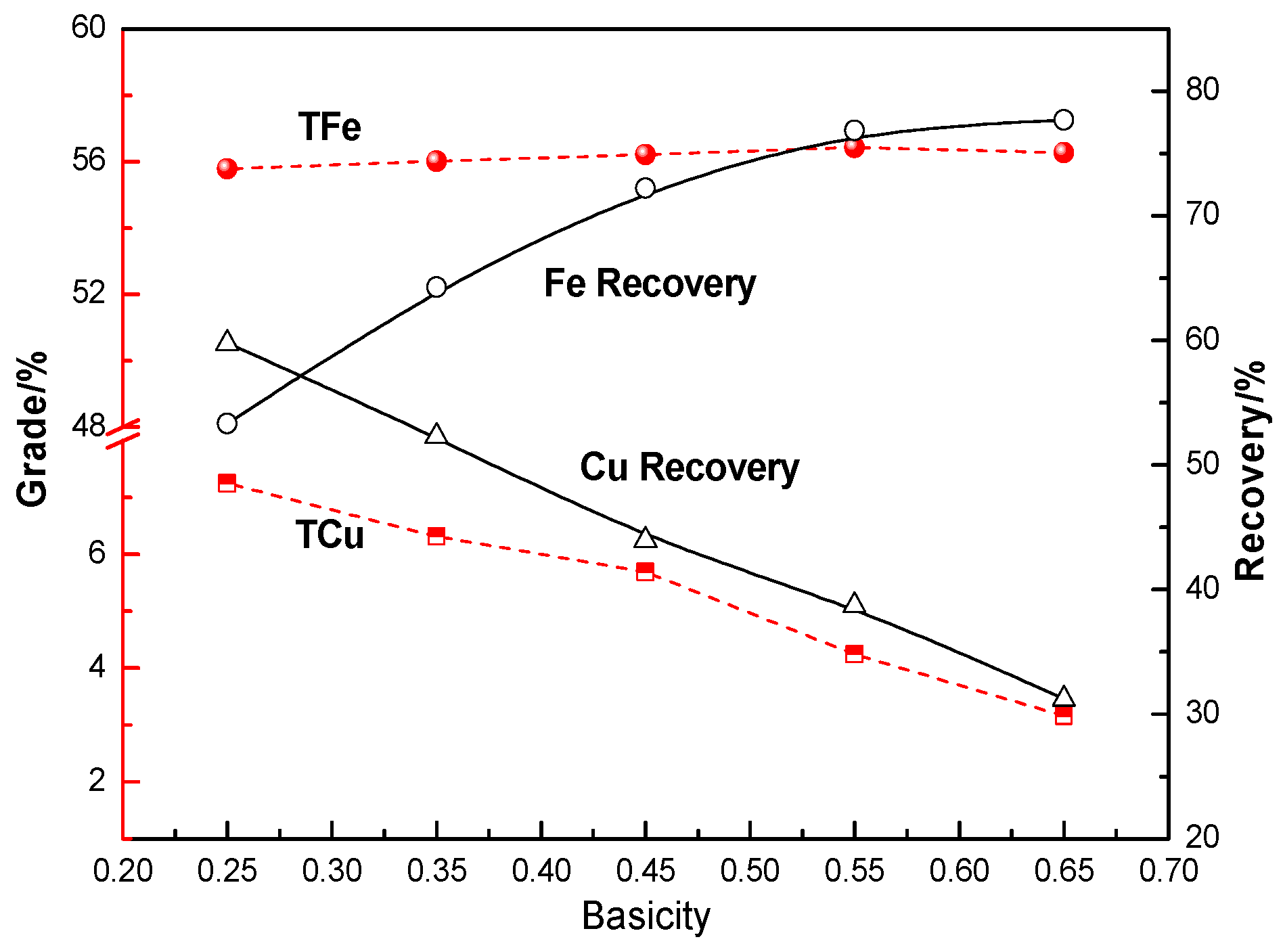
Effects of Binary Basicity on Recovery of Copper and Iron

The effect of binary basicity on modification of copper slag is presented in Figure 5. As can be seen in Figure 5, it is clear that with an increase in binary basicity from 0.25 to 0.65, the total iron grade of concentrate increases from 55.79% to 56.27% and iron recovery significantly increases from 53.32% to 77.68%. On the contrary, the copper grade of copper concentrate decreases from 7.25% to 3.16% and the copper recovery obviously decreases from 59.78% to 31.21%. This means that by adjusting the binary basicity, more iron-bearing mineral was transformed from fayalite to magnetite, resulting in higher magnetic separation recovery. This effect can be explained by the fact that the presence of calcium oxide in the sample benefited the decomposition of 2FeO·SiO2 through replacing the “FeO”, which led to an increase of the activity of free “FeO” in the slag and promoted more magnetite generation, as illustrated in Equations (3) and (4).
However, with more magnetite generated and firstly precipitated in modification and slow cooling process, the viscosity of copper slag was increased sharply, which has extremely negative influence on aggregation and growth of the particles of the copper bearing minerals, leading to more fine copper minerals formation. Thus, it is very difficult to recover the copper by flotation separation. After comprehensive consideration of recovery of iron and copper, the binary basicity was fixed at 0.45 in the subsequent experimental series.

Effects of Compound Additive Dosage on the Recovery of Copper and Iron

The flotation and magnetic separation results of cooper slag modified with variable dosages of compound additive (ranging between 3% and 15%) are shown in Figure 6.
It can be seen in Figure 6 that as the compound additive increases from 3% to 15%, the total copper grade of copper concentrate and copper recovery increases obviously, the total iron grade of magnetite concentrate changes slightly, and the iron recovery decreases sharply from 73.03% to 54.85%.
As described above, the compound additive contains sulfide, which played an important role in the modification process: The sulfide, as a kind of reducing agent, lowered the production of magnetite through reducing the Fe3O4 to FeO (as shown in Equation (7) and Figure 4), while benefiting from the viscosity of the molten slag decreasing obviously. In addition, sulfide can be added for another purpose as it helps to ensure sulfidation of all copper present in the sample so that it enters into the matte phase, since Cu2O is very easy to sulfurized to Cu2S by FeS. Thus, the content of copper sulfide, as the favorable mineral for flotation, was improved in the modified slag.
In other words, adjusting the dosage of the compound additive can improve recovery of copper through accelerating the generation of matte particles, yet the iron recovery is inhibited. Therefore, in order to comprehensively recovery copper and iron, the dosage of 12% is recommended under the experimental conditions.

3.2.2. Heating Treatment System

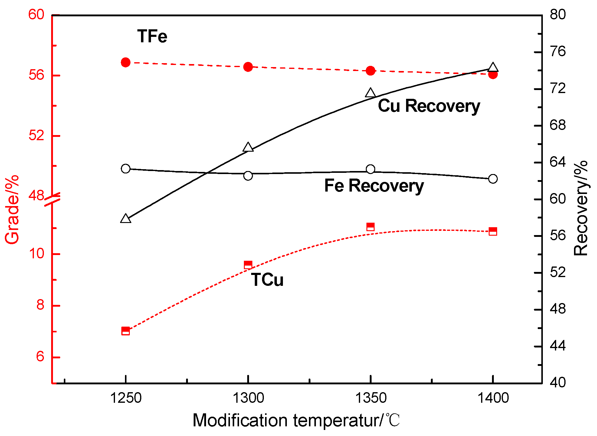
Effects of Modification Temperature on the Recovery of Copper and Iron

The effect of modification temperature on modification of copper slag is illustrated in Figure 7. As seen in Figure 7, the total copper grade of copper concentrate and copper recovery increased dramatically when the modification temperature increased from 1250 to 1400 °C, whereas the total iron grade of magnetite concentrate and iron recovery decreased slightly in the range of test temperatures.
With increasing temperature, bonded silicate anions were broken, which caused a decrease in the viscosity and an increase in fluidity of the molten slag, which contributed to collision and aggregation of matte particles. Moreover, with an increase in the temperature, the interfacial tension between two phases (copper matte and slag) ascended; on the contrary, the adhesion force of two phases descended, leading to the decrease in the dissolution and mechanical inclusion of copper in slag [25].
Therefore, from a practical point of view, the reducing temperature is fixed at 1350 °C in the subsequent experimental series.

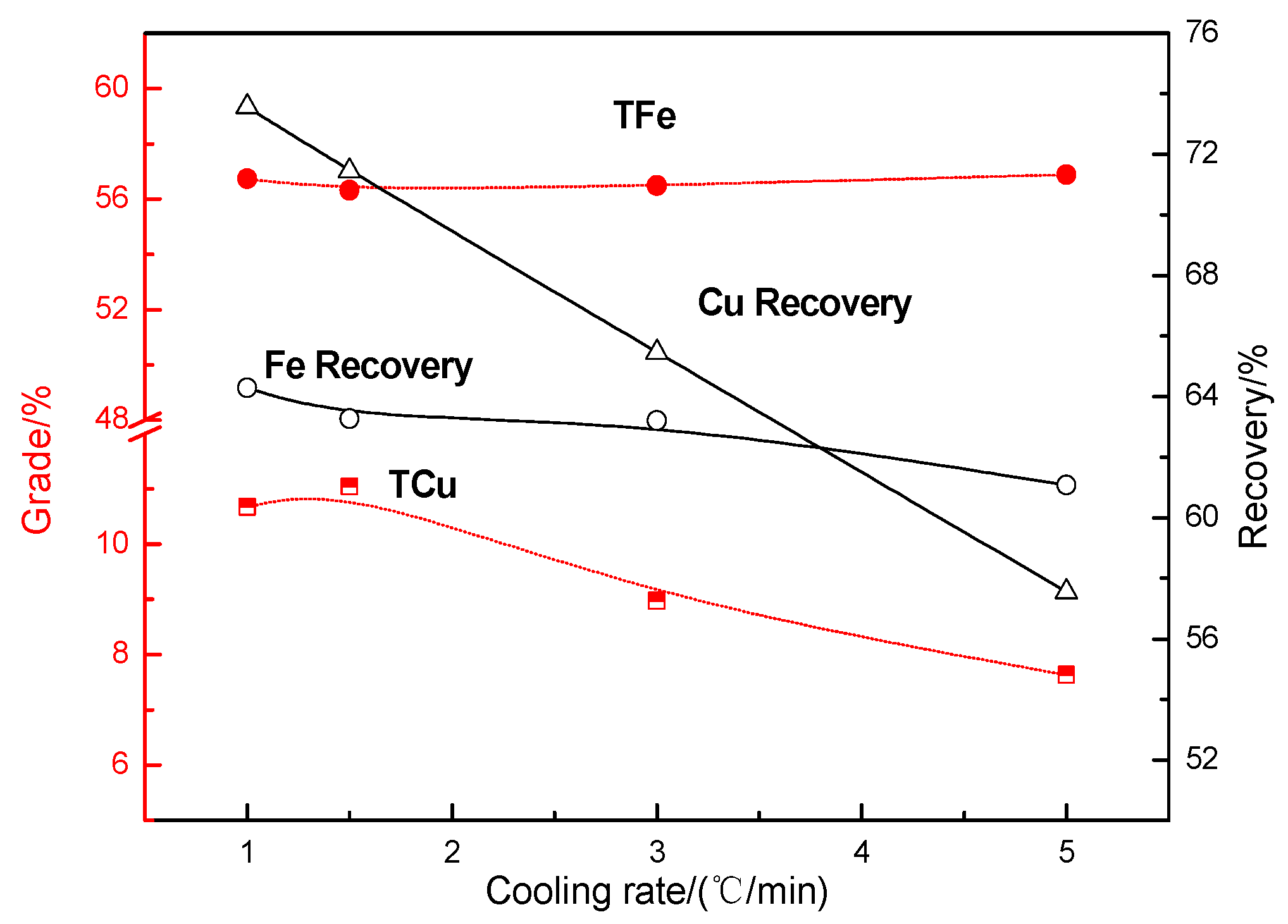
Effects of Cooling Rate on the Recovery of Copper and Iron

Figure 8 demonstrates the effect of slow cooling rate on recovery of copper and iron. It can be seen that as the slow cooling rate elevated from 1 to 5 °C/min, the total copper grade of copper concentrate decreased from 10.68% to 7.63%, the recovery of copper prominently decreased by 21.79%, the iron recovery reduced gradually from 64.29% to 61.07% and the total iron grade of magnetite concentrates remained stable. A possible explanation for this is that slow cooling of slag from its molten state to its solidification ensures full growth for the particles of valuable mineral and increases the size of the particles, thereby creating ideal mineralogy conditions for subsequent flotation and magnetic separation. In contrast, fast cooling may produce an amorphous phase to prevent diffusion and aggregation of particles, and hence the slag is more homogeneous in metal distribution and more super fine grains of valuable minerals would be generated, which is detrimental for physical separation.
In brief, the above results show that the slow cooling rate significantly influences the modification of copper slag, and the lower the cooling rate, the larger the mineral phases grow and the more valuable metals are recovered. However, in view of production efficiency, the slow cooling rate of 1.5 °C/min is recommended.

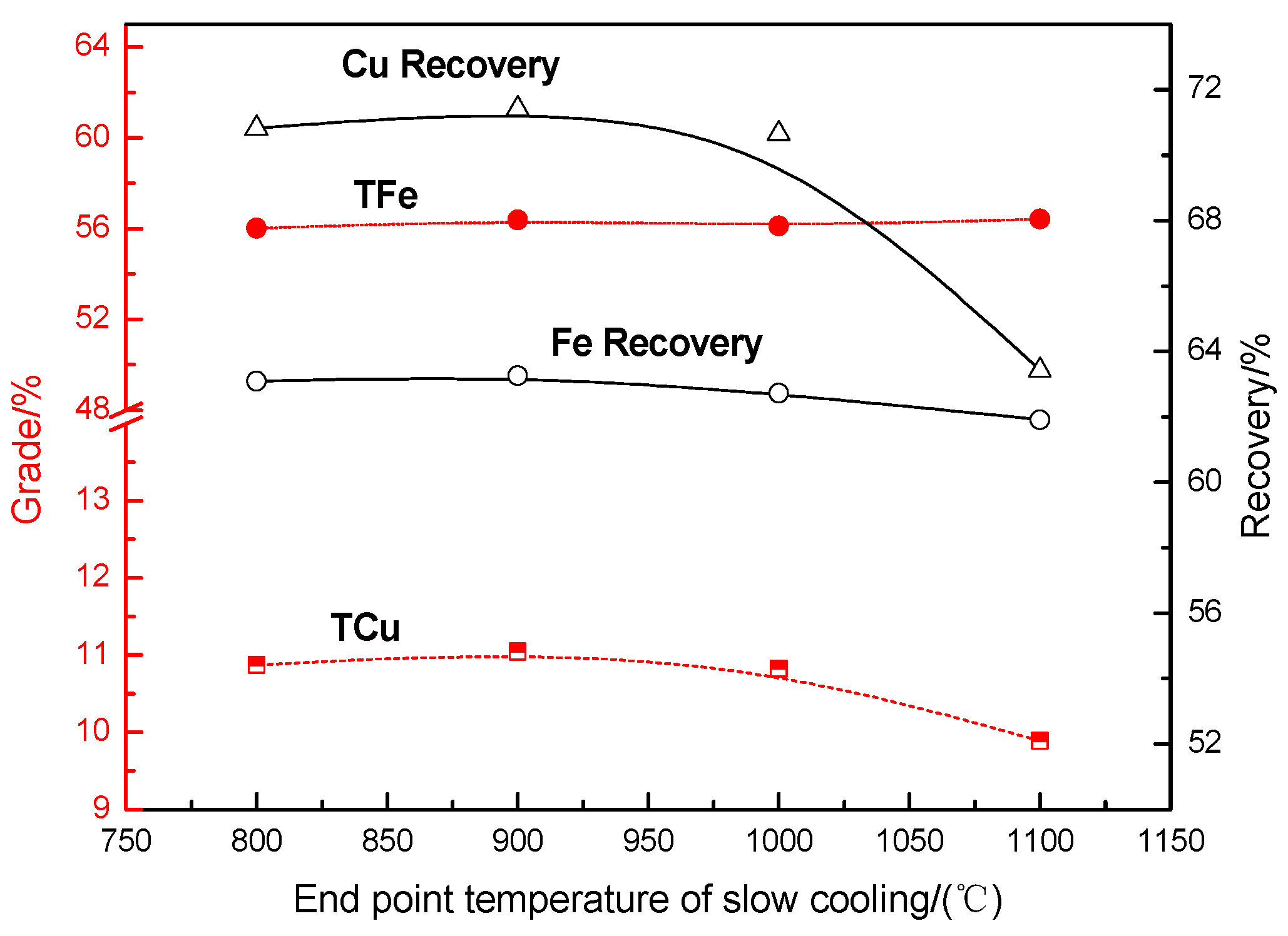
Effects of the End Point Temperature on the Recovery of Copper and Iron

The effect of the end point temperature of slow cooling on recovery of copper and iron was conducted and the results are shown in Figure 9. The results show that with the increase of end point temperature of slow cooling from 800 to 1000 °C, there is no obvious change in all evaluation indexes. However, when the end point temperature was beyond 1000 °C, the total copper grade of the rough copper concentrate and copper recovery decreased dramatically; concurrently, the total iron grade of magnetite concentrate and iron recovery change slightly. Because of high phase transition temperature and strong crystallizability of magnetite, the influence of the end point temperature of cooling in the range of tests on growth of magnetite grain is very small [28].
It is generally considered that the copper matte mainly consists of 35%–70% Cu, 20%–26% S and 10%–30% Fe, which possesses different melting point for various compositions. And the Cu-Fe-S ternary diagram indicates that the phase transition temperature of the copper matte with that consists is approximately range from 950 to 1100 °C [25]. Table 6 demonstrates the phase transition temperature of the major valuable minerals.
The molten phase is responsible for the rapid grain coarsening, where smaller particles will go into solution preferentially and precipitate on larger particles, accelerating the transport rate and fluidity as liquid diffuse much faster than solid [29,30]. Therefore, in order to ensure full aggregation and growth of mineral particles from molten state to solidification, the end point temperature of slow cooling should be below the lowest phase transition temperature of valuable minerals. Thus, it is reasonable that the end point temperature of slow cooling is fixed at 900 °C.

3.2.3. Comparison of Separation Indexes between Modified Slag and Unmodified Slag

Based on the above results, a modified slag was obtained under the conditions of 0.45 of binary basicity, blending with 12% of compound additives, modifying at 1350 °C for 120 min and cooling at 1.5 °C/min from 1350 to 900 °C. The conditions of flotation and magnetic separation process for unmodified copper slag is similar to modified copper slag, and the results compared with each other are shown in Figure 10.
As seen in Figure 10, the iron recovering from flotation tailings of two types of slag, presents a great difference in the magnetic separation process. The iron recovery was increased significantly from 32.40% to 63.26%, while the iron grade of the magnetite concentrates was similar. The improved magnetic separation efficiency of the copper slag is a result of the simultaneous increase of the content and grain size of magnetite in the slag during the modification, as the fayalite had been broken and converted into magnetite and hedenbergite, which can be confirmed by XRD pattern and microstructure characterization of copper slag (as shown in Figure 11 and Figure 12).
It can also be seen in Figure 10 that, through the modification of molten copper slag, the total copper grade of rougher copper concentrate was increased from 6.43% to 11.04%. Meanwhile, the copper recovery was changed slightly.
In addition, the chemical compositions of magnetic concentrates are shown in Table 7. It can be seen that, although the SiO2 content is a little high, impurities components such as copper and other heavy metals (Pb) are not too high. Therefore, the iron concentrates could be used to sinter blending with low SiO2 fine for iron making.

3.3. Intensification Mechanisms of Modification of Copper Slag on Cu and Fe Separation

3.3.1. Phase Transformation by Modification

In order to find the function of the modification process on phase transformation, XRD analysis was carried out to reveal the difference between modified copper slag and unmodified slag. The results are shown in Figure 11.
It can be seen from Figure 11 that in the unmodified slag, the major minerals constituents are fayalite (Fe2SiO4) and magnetite (Fe3O4). With the modification process, the peak intensity of magnetite increased significantly, and that of fayalite decreased obviously; simultaneously, hedenbergite, as a new phase, was detected in modified slag. When the binary basicity is low (less than 1), the CaO is reactive with fayalite (Fe2SiO4) to form hedenbergite (CaFeSi2O6) instead of wollastonite (CaSiO3) [26], which is not helpful with recovering of iron.
Generally, analysis of XRD assumes that the ratio of the peak heights in the XRD patterns is proportional to the mineral content, and that, for the same mineral, the variation in the diffraction intensity can approximately reflect the change in its content [31]. Thus, this implies that the amount of magnetite increases significantly in the modified copper slag, leading to an obvious improvement of iron recovery in magnetic separation.
Hence, the results above further indicate recycling potential may be enhanced by post-process additions to the high temperature slag to change its composition (that is, modifying stage of slag processing) for obtaining the target minerals—without interfering with the metallurgical process.

3.3.2. Microstructure Character of Copper Slag

Although beneficiation of copper and iron may be improved by modifying process from a perspective of mineral phases, the effects of physical separation also depend on embedded characters of slag and the size of target mineral particles. To further reveal the mechanism of the modification on improvement of mineralography and the growing character of valuable mineral particles, the microstructures of the slag were studied using an optical microscope, scanning electron microscope and energy dispersive spectrometer (SEM-EDS). The results are shown in Figure 12 and Figure 13.
Figure 12A,B is the microstructure of unmodified slag. It can be seen that the matte phase occurs as brilliant yellow prill within the silicates, which is finely disseminated throughout the slag. In addition, all prills have the same spheroidal shape, and their size has a wide range between about 5 and 30 μm with an average of approximately 15 μm. Meanwhile, magnetite was seen to be present as patches or tiny laths, showing dendritic texture and stars of various shapes with fine sizes embedded in the silicates. However, the fine dissemination of the minerals responds very poorly to flotation and magnetic separation due to the insufficient mineral liberation from the gangue mineral through grinding. Therefore, the main purpose of modifying the copper slag in molten stage is that the particles of valuable minerals were induced to grow up. As seen in Figure 12C,D most of the matte particles in the slag aggregate together as well as grow obviously; the size of which is mostly over 50 μm. Moreover, the magnetite not only presents a very large particle size but also has agglomeration to some extent, which is extremely beneficial to magnetite separation.
Moreover, the liberation of minerals is important for flotation and magnetic separation. Thus, liberation degree of valuable metal minerals under different grinding sizes for modified slag was determined, and the results are shown in Table 8, indicating that when the grinding fineness of the slag is up to 70% passing through 74 μm, copper matte and magnetic minerals are liberated enough and the grain size is favorable to the separation process.
Mineral compositions of modified slag were determined by spot analysis of minerals using SEM-EDS, and the results are shown in Figure 13. The analysis on point 1 indicates that it predominantly consists of Fe and O (magnetite) along with traces of Al, Mg and Zn. According to EDS analysis of point 2 in Figure 13, the major gangue minerals mainly consist of hedenbergite (CaO·FeO·2SiO2), which is in agreement with the XRD results in Figure 11. Meanwhile, the point analysis of the spherical shaped phase (point 3) contains high copper percentage with little iron and sulfur, as anticipated, which exhibits Cu bearing phase similar to matte (Cu2S-FeS). As can be seen in Figure 14, that FeS has a high affinity with copper to form a solid solution with Cu2S of a limited solubility. Taken together with the thermodynamic analysis, adding the additives with FeS is favorable to form matte in the slag, leading to promoted recovery of copper.

4. Conclusions

The feasibility of an integrated technological route to improve beneficiation of copper and iron components from copper slag through modification of molten slag was investigated, and the following conclusions were achieved:
(1)
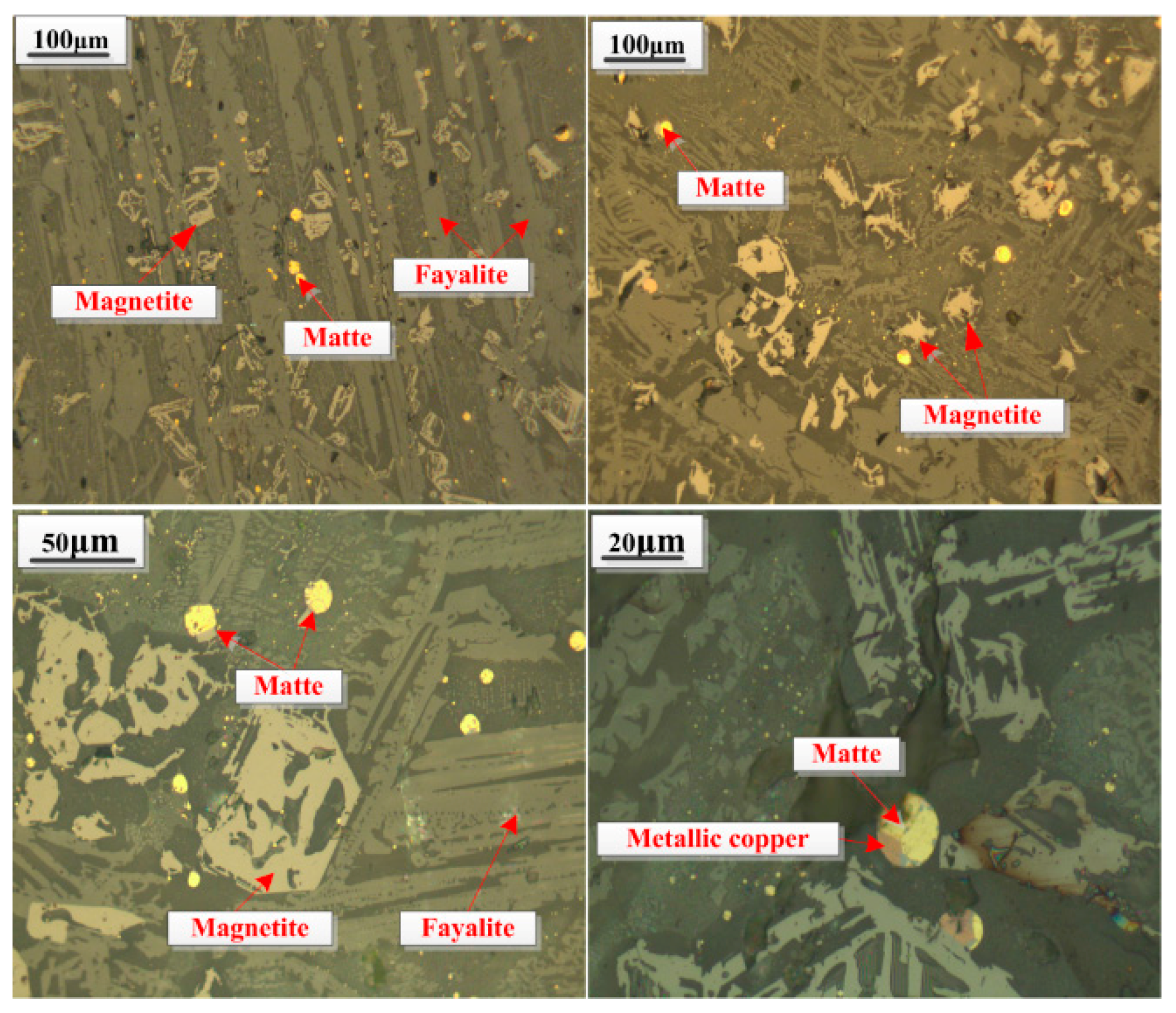
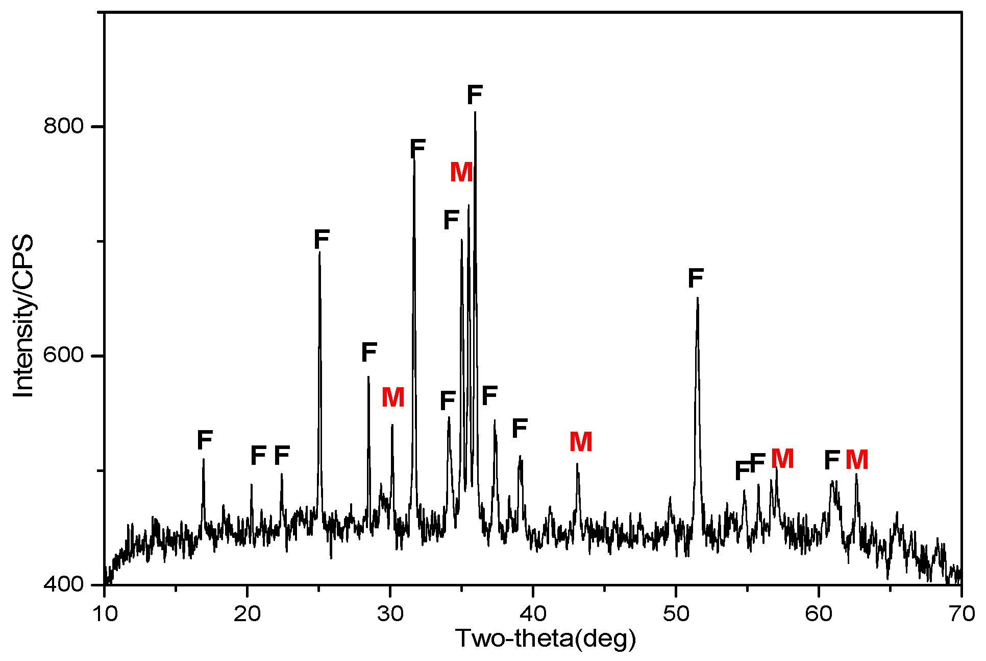
Iron element in the copper slag mainly existed in the form of fayalite and magnetite, and the copper is present in sulfide form with fine size as well as being closely embedded in the fayalite matrix, revealing that traditional physical beneficiation process may result in poor valuable metal recovery.
(2)
The modification process for copper slag was conducted to improve the recovery of copper and iron with the optimized conditions at 0.45 binary basicity, 12% compound additive, modifying at 1350 °C for 120 min, and cooling at 1.5 °C/min down to 900 °C. The physical beneficiation studies showed that compared with unmodified slag, copper grade of rougher copper concentrate was increased from 6.43% to 11.04%; meanwhile, the copper recovery was kept about 72%, the corresponding iron recovery was increased significantly from 32.40% to 63.36%, and the total iron grade of magnetite concentrate was similar.
(3)
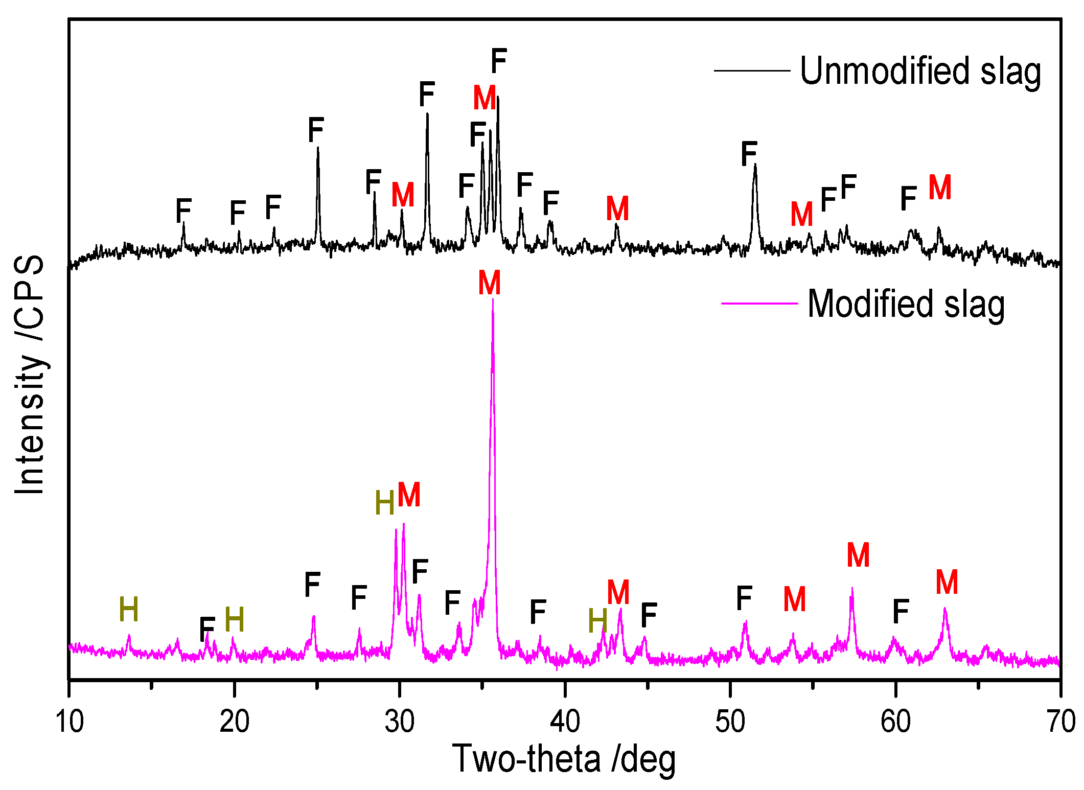
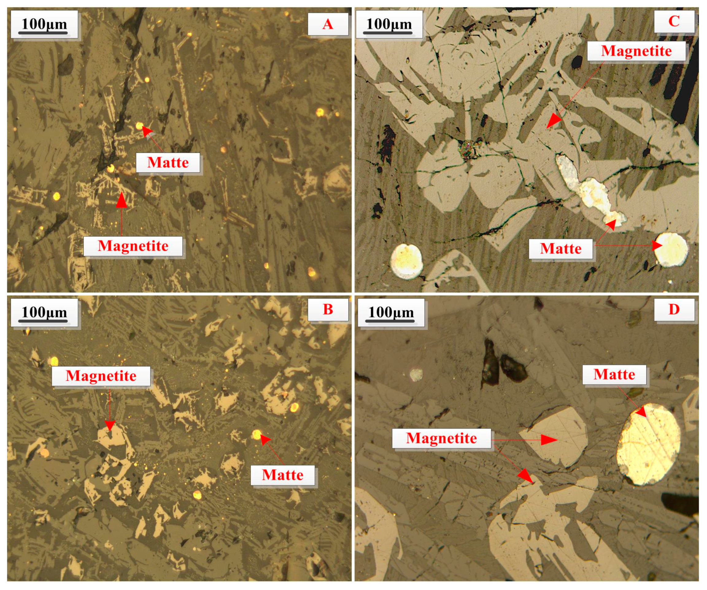
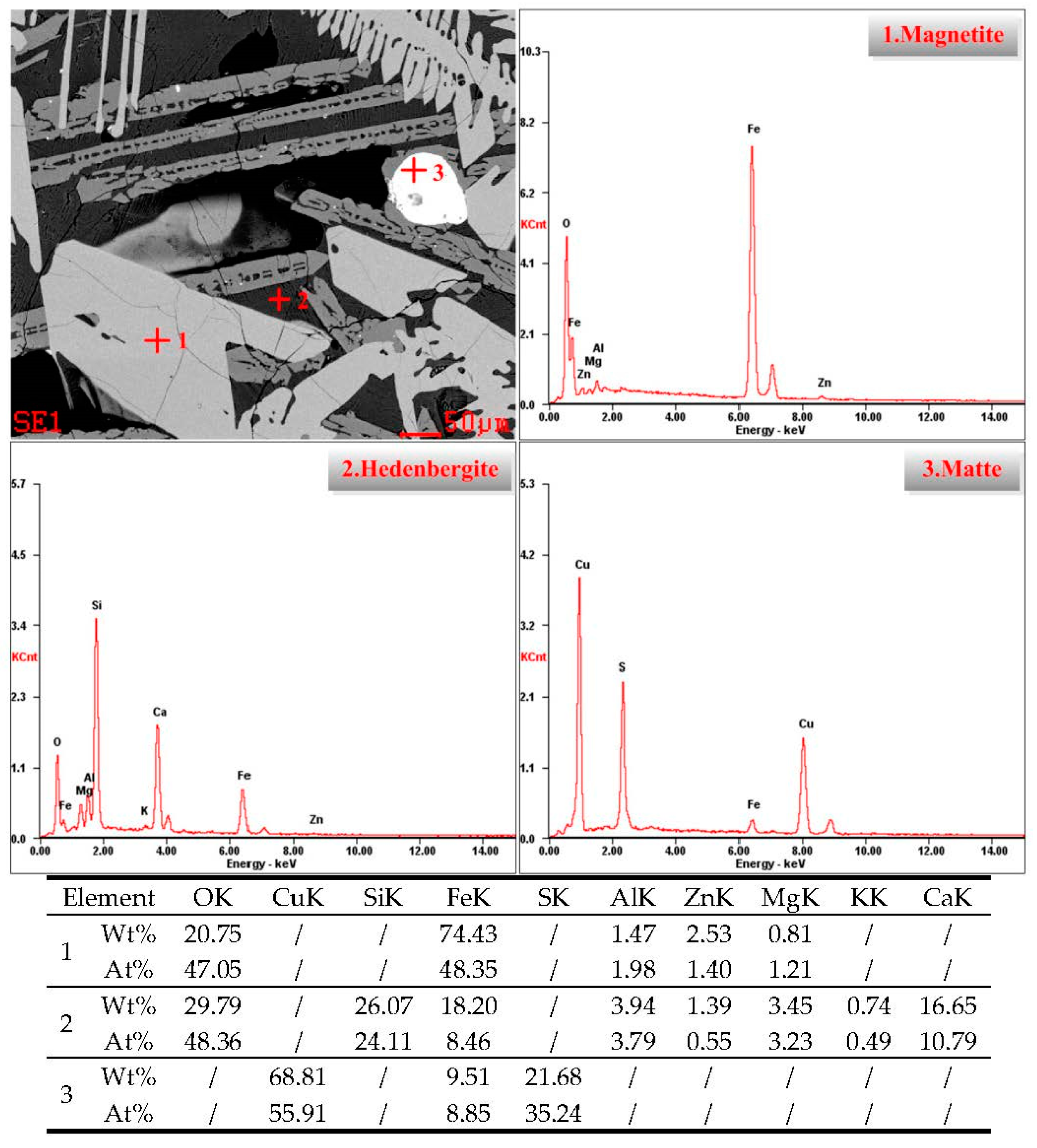
XRD analysis showed that the reconstruction of mineral phases for copper slag is effective because more fayalite was transformed to magnetite, which is beneficial to magnetic separation. Optical microscopy and ESEM-EDS analysis of modified slag indicated that valuable mineral (matte and magnetite) particles in the slag aggregate together and grow obviously, and the size is mostly over 50 μm, which is extremely favorable to the beneficiation of copper and iron.

Acknowledgments

The authors wish to express their thanks to the National Key Technology R & D Program of China (NO. 2013BAB03B04) for the financial support of this research, and also would like to thank Co-Innovation Center for Clean and Efficient Utilization of Strategic Metal Mineral Resources of Hunan Province, which supplied us the facilities and funds to fulfill the experiments.

Author Contributions

Deqing Zhu, Zhengqi Guo and Jian Pan conceived and designed the experiments; Zhengqi Guo, Feng Zhang and Tengjiao Wu performed the experiments; Zhengqi Guo wrote the paper; and Deqing Zhu and Jian Pan modified the paper.

Conflicts of Interest

The authors declare no conflict of interest.

References

  1. Davenport, W.G.L.; King, M.; Schlesinger, M.; Biswas, A.K. Extractive Metallurgy of Copper; Pergamon Press: Oxford, UK, 2002. [Google Scholar]
  2. Gorai, B.; Jana, R.; Premchand, M. Characteristics and utilization of copper slag—A review. Resour. Conserv. Recycl. 2003, 39, 299–313. [Google Scholar] [CrossRef]
  3. Shen, H.; Forssberg, E. An overview of recovery of metals from slags. Waste Manag. 2003, 23, 933–949. [Google Scholar] [CrossRef]
  4. Shi, C.; Meyer, C.; Behnood, A. Utilization of copper slag in cement and concrete. Resour. Conserv. Recycl. 2008, 52, 1115–1120. [Google Scholar] [CrossRef]
  5. Alpa, I.; Deveci, H.; Sungun, H. Utilization of flotation wastes of copper slag as raw material in cement production. J. Hazard. Mater. 2008, 159, 390–395. [Google Scholar] [CrossRef] [PubMed]
  6. Wang, H. Recovery of copper and iron in the converter slag from a copper smelter (in Chinese). J. Guangdong Nonferr. Met. 2003, 13, 83–88. [Google Scholar]
  7. Al-Jabri, K.; Taha, R.; Al-Ghassani, M. Use of copper slag and cement by-pass dust as cementitious materials. Cem. Concr. Aggreg. 2002, 24, 7–12. [Google Scholar]
  8. Antonijevica, M.M.; Dimitrijevic, M.D.; Stevanovic, Z.O.; Serbula, S.M.; Bogdanovic, G.D. Investigation of the possibility of copper recovery from the flotation tailings by acid leaching. J. Hazard. Mater. 2008, 158, 23–34. [Google Scholar] [CrossRef] [PubMed]
  9. Roy, S.; Rehani, S. Flotation of copper sulphide from copper smelter slag using multiple collectors and their mixtures. Int. J. Miner. Process. 2015, 143, 43–49. [Google Scholar] [CrossRef]
  10. Sarrafi, A.; Rahmati, B.; Hassani, H.R. Recovery of copper from reverberatory furnace slag by flotation. Miner. Eng. 2004, 17, 457–459. [Google Scholar] [CrossRef]
  11. Barnes, C.; Lumsdaine, J.; Hare, S. Copper converter slag treatment at Mount Isa Mines Limited, Mount Isa, Qld. AusIMM Proc. 1993, 298, 31–35. [Google Scholar]
  12. Bruckard, W.J.; Somerville, M.; Hao, F. The recovery of copper, by flotation, from calcium-ferrite-based slags made in continuous pilot plant smelting trials. Miner. Eng. 2004, 17, 495–504. [Google Scholar] [CrossRef]
  13. Mawejaa, K.; Mukongob, T.; Mutomboc, I. Cleaning of a copper matte smelting slag from a water-jacket furnace by direct reduction of heavy metals. J. Hazard. Mater. 2009, 164, 856–862. [Google Scholar] [CrossRef] [PubMed]
  14. Altundogan, H.S.; Tumen, F. Metal recovery from copper converter slag by roasting with ferric sulphate. Hydrometallurgy 1997, 44, 261–267. [Google Scholar] [CrossRef]
  15. Urosevic, D.; Dimitrijevic, M.; Jankovic, Z.; Antic, D. Recovery of copper from copper slag and copper slag floatation tailings by oxidative leaching. Physicochem. Probl. Miner. Process. 2015, 51, 71–82. [Google Scholar]
  16. Muravyov, I.; Fomchenko, V.; Usoltsev, V.A.; Vasilyev, F.K. Leaching of copper and zinc from copper converter slag flotation tailings using H2SO4 and biologically generated Fe2(SO4)3. Hydrometallurgy 2012, 119, 40–46. [Google Scholar] [CrossRef]
  17. Zheng, J.; Xiao, K. The research on using dispersant agent to lron recovery in copper slag (in Chinese). Nonferr. Met. Sci. Eng. 2011, 6, 71–73. [Google Scholar]
  18. Yang, T.; Hu, J.; Wang, H. Concentration of Fe3O4 in roasted slag from copper impoverishment smelting (in Chinese). Chin. J. Process Eng. 2011, 11, 613–619. [Google Scholar]
  19. Yang, H.; Jing, L.; Dang, C. Iron recovery from copper-slag with lignite-based direct reduction followed by magnetic separation (in Chinese). Chin. J. Nonferr. Met. 2011, 21, 1165–1170. [Google Scholar]
  20. Yucel, O.; Sahin, F.; Sirin, B.; Addemir, O. A reduction study of copper slag in DC arc furnace. Scand. J. Metall. 1999, 28, 93–99. [Google Scholar]
  21. Zhou, X.L.; Zhu, D.Q.; Pan, J.; Wu, T.J. Utilization of waste copper slag to produce directly reduced Iron for weathering resistant steel. Int. ISIJ 2015, 55, 1347–1352. [Google Scholar]
  22. Kim, S.B.; Jo, S.K.; Shin, D.; Lee, J.C.; Jeong, S.B. A physico-chemical separation process for upgrading iron from waste copper slag. Int. J. Miner. Process. 2013, 124, 124–127. [Google Scholar] [CrossRef]
  23. Heo, J.H.; Kim, B.S.; Park, J.H. Effect of CaO addition on iron recovery from copper smelting slags by solid carbon. Metall. Mater. Trans. B 2013, 44, 1352–1363. [Google Scholar] [CrossRef]
  24. Durincka, D.; Engströmb, F.; Arnouta, S.; Heulensa, J.; Jonesa, P.T.; Björkmanb, B.; Blanpaina, B.; Wollants, P. Hot stage processing of metallurgical slags. Resour. Conserv. Recycl. 2008, 52, 1121–1131. [Google Scholar] [CrossRef]
  25. Fu, C. Nonferrous Metallurgy Principle; Metallurgical Industry Press: Beijing, China, 1984; pp. 1132–1145. [Google Scholar]
  26. Fu, J.; Jiang, T.; Zhu, D. Sintering and Pelletizing; Central South University of Technology Press: Changsha, China, 1996; pp. 100–142. [Google Scholar]
  27. Zhu, Z.Z.; He, J.Q. Metallurgy of Copper; Science Press: Sunyang, China, 2003; pp. 356–432. [Google Scholar]
  28. Zhang, L.N.; Zhang, L.; Wang, M.Y.; Che, Y.C.; Sui, Z.T. Thermodynamics of phase transformations in oxidation process of CaO-FeOx-SiO2 system with high iron content (in Chinese). Acta Phys. Sin. 2008, 24, 1540–1546. [Google Scholar]
  29. Chang, Y.A. Phase Relationships and Thermodynamics of the Ternary Copper-Iron-Sulfur System, Extractive Metallurgical of Copper; The Metallurgical Society of AIME: New York, NY, USA, 1976; pp. 367–397. [Google Scholar]
  30. German, R.M.; Suri, P.; Park, S.J. Review: Liquid phase sintering. J. Mater. Sci. 2009, 44, 1–39. [Google Scholar] [CrossRef]
  31. Konga, L.X.; Bai, J.; Li, W. The internal and external factor on coal ash slag viscosity at high temperatures, Part 1: Effect of cooling rate on slag viscosity, measured continuously. Fuel 2015, 158, 968–975. [Google Scholar] [CrossRef]
Figure 1. X-ray diffraction patterns of copper slag (F—fayalite; M—magnetite).
Metals 06 00086 g001
Figure 2. Microstructure of copper slag.
Metals 06 00086 g002
Figure 3. Schematic flow sheet of the modification-beneficiation process of copper slag.
Metals 06 00086 g003
Figure 4. Relationship between aFeS and aFe3O4 in molten slag.
Metals 06 00086 g004
Figure 5. Effects of binary basicity on recovering of copper and iron (Modifying at 1350 °C for 120 min with 6% of compound additive and cooling at 1.5 °C/min from 1350 to 900 °C).
Metals 06 00086 g005
Figure 6. Effects of compound additive dosage on recovering of copper and iron (0.45 of binary basicity, modifying at 1350 °C for 120 min and cooling at 1.5 °C/min from 1350 to 900 °C).
Metals 06 00086 g006
Figure 7. Effects of slag modification temperature on recovering of copper and iron (0.45 of binary basicity, blending with 12% of compound additive, modifying for 120 min and cooling at 1.5 °C/min from 1350 to 900 °C).
Metals 06 00086 g007
Figure 8. Effects of slow cooling rate on recovering of copper and iron (0.45 of binary basicity, blending with 12% of compound additive, modifying at 1350 °C for 120 min and cooling down to 900 °C).
Metals 06 00086 g008
Figure 9. Effects of end point temperature of slow cooling on the recovering of copper and iron (0.45 of binary basicity, blending with 12% of compound additive, modifying at 1350 °C for 120 min and cooling at 1.5 °C/min).
Metals 06 00086 g009
Figure 10. Comparison of beneficiation indexes of copper and iron between two kinds of slags.
Metals 06 00086 g010
Figure 11. XRD patterns of the copper slag (0.45 of binary basicity, blending with 12% of compound additive, modifying at 1350 °C for 120 min and cooling at 1.5 °C/min from 1350 to 900 °C) (F—fayalite; M—magnetite; H—hedenbergite).
Metals 06 00086 g011
Figure 12. Microstructures of the copper slag (0.45 of binary basicity, blending with 12% of compound additive, modifying at 1350 °C for 120 min and cooling at 1.5 °C/min down to 900 °C): (A,B) unmodified slag; and (C,D) modified slag.
Metals 06 00086 g012
Figure 13. Scanning electron microscope and energy dispersive spectrometer (SEM-EDS) analyses of the modified slag (0.45 of binary basicity, blending with 12% of compound additive, modifying at 1350 °C for 120 min and cooling at 1.5 °C/min down to 900 °C).
Metals 06 00086 g013
Figure 14. Cu2S-FeS1.08 binary phase diagram.
Metals 06 00086 g014
Table 1. Chemical compositions of copper slag (wt. %).
ElementTFeFeOSiO2CaOMgOAl2O3CuPbSPLOI
Percentage39.1042.8531.112.441.792.290.800.130.450.100.88
Table 2. The distribution of iron in associated minerals (wt. %).
MineralFerric SulfateMagnetiteIron SulfideHematiteFayaliteFetotal
Content0.4112.850.013.7522.0839.10
Fraction1.0532.860.039.5956.47100.00
Table 3. The distribution of copper in associated minerals (wt. %).
MineralCopper OxideMetallic CopperCopper SulfideCombined Copper OxideCutotal
Content0.020.180.460.140.80
Fraction2.5022.5057.5017.50100.00
Table 4. Chemical compositions of compound additive (wt. %).
ElementTFeSiO2CaOMgOAl2O3MnOCuS
Percentage52.442.090.770.681.639.31.2312.13
Table 5. Equilibrium constants for Equation (5) at different modification temperatures.
Modification Temperature/°C1250130013501400
Equilibrium constant1.91 × 1041.33 × 1040.94 × 1040.69 × 104
Table 6. Phase transition temperature of the main valuable minerals (°C).
MineralFeSCu2SCuCu2S-FeS (Matte)
temperature119011261083950–1100
Table 7. Chemical compositions of iron concentrate (mass fraction, %).
ElementTFeSiO2CaOMgOAl2O3SPCuPbZn
Percentage56.317.222.590.642.750.030.040.150.030.03
Table 8. Liberation degree of metal minerals under different grinding sizes for modified slag/%.
MineralsGrinding Size/(−0.074 mm %)
53586470768285
Copper matte76.3484.3488.6593.2195.6897.1298.03
Magnetic89.6393.2394.5695.7896.8297.5198.32

