1. Introduction
Industrial structures, including ships and offshore structures, are subject to periodic and arbitrary loadings. These phenomena lead to crack propagation and fracture of the structures. In order to prevent such catastrophic disaster, fatigue analysis and fatigue life assessment should be carried out prior to the design steps.
Miner’s accumulative damage calculation and Goodman fatigue calculation are the representative fatigue life evaluation methods under regular and irregular cyclic loading. If there is an initial crack included in the material or structural member, the fatigue life and fatigue crack growth rate can change under the operating environments of the structure. For this reason, the fatigue crack growth rate (FCGR) test is commonly adopted to investigate the crack growth characteristics of materials [
1].
The estimation of FCGR characteristics has mainly been performed by an experimental approach. Through the test, the correlation between the crack growth rate d
a/d
N and the applied stress intensity factor range ∆
K can be estimated [
2].
However, it requires enormous time and cost to establish the required experimental facilities and conditions. In addition, it is extremely difficult to reproduce harsh environments such as cryogenic and high temperatures. For this reason, there are many limitations to carrying out the FCGR test effectively. As a result, computational simulation has been considered as an alternative method to solve these problems.
In computational simulation, two kinds of approaches have been principally adopted, namely, a cohesive zone model (CZM) and an extended finite element method (XFEM).
In the CZM theory, a crack is propagated through the separation surface (or cohesive zone) when the cohesive separation force is greater than the cohesive traction force. The crack propagation problems of brittle/cementitious materials, in which a nonlinear zone ahead of the crack tip is generated because of plasticity and microcracking near the cracked region, can be analyzed using the CZM [
3]. There are many researchers who solve the fatigue crack growth problem using the CZM. For example, de-Andres
et al. have solved a three-dimensional fatigue crack phenomenon and estimated the fatigue life of an aluminum shaft under axial loading using a three-dimensional cohesive element and an irreversible cohesive law [
4]. Yang
et al. have proposed a simulation method for fatigue crack initiation and propagation in quasi-brittle materials using the CZM [
5], and Roe and Siegmund have studied fatigue crack growth along an interface using the actual process of material separation, and not by using Paris’ law [
6]. In their research, it was found that the traction-separation behavior does not follow a predefined traction-separation path as posited by the classical CZM. Hence, an improved CZM has been proposed on the basis of three types of viewpoints, namely, (i) the consideration and application of a traction-separation law considering unloading in both normal and shear separation in the cohesive zone; (ii) the development of an evolutionary damage law in order to analyze failure under subcritical loading in dependence of the accumulated separation and the current resultant traction in the cohesive zone; and (iii) the establishment of a contact model. In addition, Bouvard
et al. have carried out a numerical analysis of the fatigue and creep-fatigue crack growth of single crystal superalloys using an irreversible CZM [
7]. In order to calculate the fatigue damage accumulation under cyclic loads, a damage-coupled CZM has been proposed, and damage accumulation and stagnation phenomena under loading and unloading conditions have been quantitatively predicted. Ural
et al. have developed a damage-based cohesive model in which the coupled model is fabricated by the combination of the linear damage-dependent traction-separation relation and the damage evolution equation [
8].
On the other hand, the handicaps of the classical finite element method (FEM) for crack propagation simulation, such as an impractical crack growth shape and node singularity, have been improved by the XFEM. For using XFEM, a standard displacement-based approximation has been enriched near a crack by incorporating both the discontinuous fields and the near-tip asymptotic fields through a partition of unity method. On the basis of this technique, the entire crack is represented independently of the mesh; hence, a remeshing technique is not necessary to describe the crack growth [
9]. The XFEM is most recent proposed method, and outstanding studies have been carried out since 1999. Stolarska
et al. have developed a level set method (LSM)-coupled XFEM algorithm [
10]. The LSM and XFEM were adopted to represent the crack tip location prior to the crack growth and the rate of crack growth, respectively. In addition, Sukumar
et al. have proposed a fast marching method (FMM)-coupled XFEM technique [
11]. In order to describe the crack front in an FE model, the FMM was combined with Paris’ law. Moreover, the stress intensity factor for planar three-dimensional cracks was calculated, and the fatigue crack growth was simulated using the XFEM. Shi
et al. have programmed an ABAQUS user-defined material subroutine (UMAT) and element subroutine (UEL) for the practical simulation of fatigue crack growth of a compact tension specimen using the FMM-XFEM technique [
12].
The aforementioned studies using both types of methods show good agreement with the fatigue crack growth experiments using a compact tension specimen, a notched plate, etc. In other words, the correlation between da/dN and ∆K in the stable crack growth region, i.e., region II, has been well predicted. However, these methods require experiments prior to simulation to identify the material parameters of the governing equation, which is a function of the critical stress intensity factor, the cohesive fracture energy variable, and the critical crack opening value. Although these numerical methods have been verified sufficiently for simulating fatigue crack growth, a large number of experiments are required to determine the moment and realm of crack occurrence while considering information about the initial crack such as shape and position.
In contrast with these techniques, damage mechanics has been introduced as a new method for expressing the fatigue crack growth phenomena. Damage mechanics is based on thermodynamic micromechanical approaches, and has provided governing equations that can be incorporated into the material constitutive equation to express the material degradation that causes crack initiation and propagation [
13,
14,
15,
16,
17].
One of the distinctive factors of damaged materials under arbitrary loads is material degradation due to void and slip. In particular, the elastic stiffness variable/matrix is degraded because of these micro-defects. There is an inverse relationship between elastic stiffness and material defects. In the case of the damage mechanism, degradation of elastic stiffness and void/slip growth can be represented by an effective elastic stiffness model and a damage evolution model, respectively. On the basis of the correlation between these two models, the material/structural degradation under various loads, such as fatigue, creep, brittle, and ductile failures, can be evaluated and predicted quantitatively [
18,
19,
20]. Furthermore, in order to analyze the damage/failure behavior of materials precisely, it is crucial to select a suitable damage evolution model from among the possible choices.
There are a few damage evolution models that describe the various types of material failures, such as elastic-plastic ductile damage [
19,
21,
22,
23], fatigue damage [
24,
25,
26,
27], creep and creep-fatigue damage [
28,
29,
30], and elastic-brittle damage [
31,
32,
33,
34]. In the case of low-cycle fatigue, some research has been performed. Hamon
et al. proposed a damage model for fatigue crack propagation. The model is based on two damage mechanisms that consider static and cyclic damage on fatigue crack propagation. In this study, d
a/d
N and ∆
K curves at different load ratios were obtained numerically (typical results for FCGR tests) and the proposed model showed good agreement with experimental results. However, there are few studies on how to predict fatigue life under high-cycle fatigue for various types of metal and nonmetal materials. Additional mechanisms such as two-scale damage are required to express crack propagation under high-cycle fatigue that occurs in an elastic regime.
Three difficulties must be overcome to computationally assess the fatigue crack grow rate using a finite element analysis (FEA) based on damage mechanics: (i) the selection of an appropriate material constitutive model to express the material’s plastic behavior and evolution of the damage; (ii) a method for simulating the crack propagation based on the calculation results using the material constitutive model; and (iii) the time costs for the computation, which can be more difficult in the case of high cycle fatigue problems.
In the authors’ previous study, simulations of the crack propagation were performed under monotonic loading conditions at room and cryogenic temperatures and moreover, the fracture capacities of SUS304L were also estimated computationally at both temperatures [
35]. A previously proposed method based on a material constitutive model is verified by the comparison of the results, such as the strain energy release rate,
GIC, failure mode, and force-displacement relationship, from the experimental and computational fracture tests. This computational method could be a solution for first two difficulties mentioned above. The constitutive model used sufficiently expressed the materials’ plastic behavior including strong hardening at cryogenic temperatures and the evolution of damage of SUS304L. Crack propagations, including fracture mode, are also simulated based on a calculated damage variable using the element weakening method [
35,
36]. Therefore, in the present study, for the numerical estimation of fatigue fracture, the aforementioned computational method using a material constitutive model including damage evolution model is employed again. In addition, the jump-in-cycles procedure and a numerical approach rearranging critical damage are employed for fatigue damage analysis, in order to reduce the computational times and to consider the fatigue fracture phenomenon differently from ductile fracture under static loading, respectively (these numerical approaches can be solution for the last difficulty as presented before). The aforementioned procedure and numerical approach for fatigue damage analysis are also implemented in ABAQUS UMAT. Finally, in the present study, a computational FCGR tests using the proposed ABAQUS UMAT for 7% nickel steel are carried out at room and cryogenic temperatures. The obtained numerical results were verified by comparing them with the experimental results.
2. Experimental FCGR Tests
Before the numerical evaluation of the fatigue crack growth rate for 7% nickel steel, experimental tests are performed. The experimental test results are compared with the numerical results in order to validate the computational method proposed in the present study. Compact tension (CT) type specimens for fatigue tests were tested at both the room temperature and the cryogenic temperature (−163 °C). The cryogenic temperature was selected in consideration of the temperature at which liquefied natural gas (LNG) is stored.
The FCGR test is conducted according to ASTM E647 [
37]. The test method involves cyclic loading of notched specimens that have been acceptably precracked by fatigue. The crack size is measured, either visually or by an equivalent method, as a function of the elapsed fatigue cycles, and these data are subjected to numerical analysis to establish the rate of crack growth. Crack growth rates are expressed as a function of the stress-intensity factor range, ∆
K, which is calculated from expressions based on linear elastic stress analysis.
2.1. Test Specimens
Nickel is recognized to enhance fracture toughness of materials at low temperatures. Therefore, nickel is widely employed as an ingredient in materials for constructing industrial structures, such as LNG carrier storage systems. In particular, 7% nickel steel has being recently applied in LNG carrier storage systems in order to replace 9% nickel steel, which requires a considerable amount of expensive welding materials. However, only a few studies have been carried out to assess the fracture capacity of 7% nickel steel at both the room temperature and the cryogenic temperature.
The chemical composition of 7% nickel steel, which is selected for the study of the fatigue crack growth rate test, is summarized in
Table 1.
Table 1.
Chemical composition of 7% nickel steel (wt. %).
| Element | C | Si | Mn | P | S | Cu | Ni |
|---|
| weight % | 0.05 | 0.05 | 0.80 | 0.001 | 0.001 | 0.03 | 7.13 |
| Element | Cr | Mo | Nb | V | Ti | Sol. Al |
| weight % | 0.41 | 0.04 | <0.003 | <0.003 | <0.003 | 0.030 |
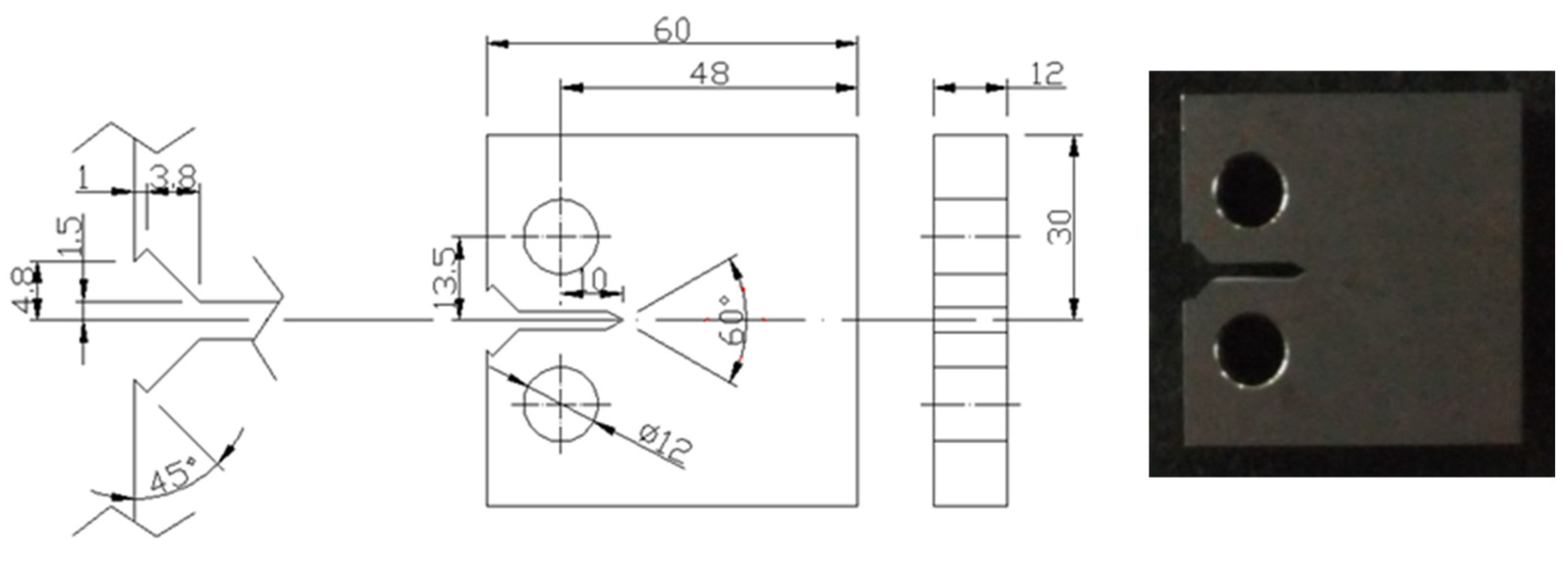
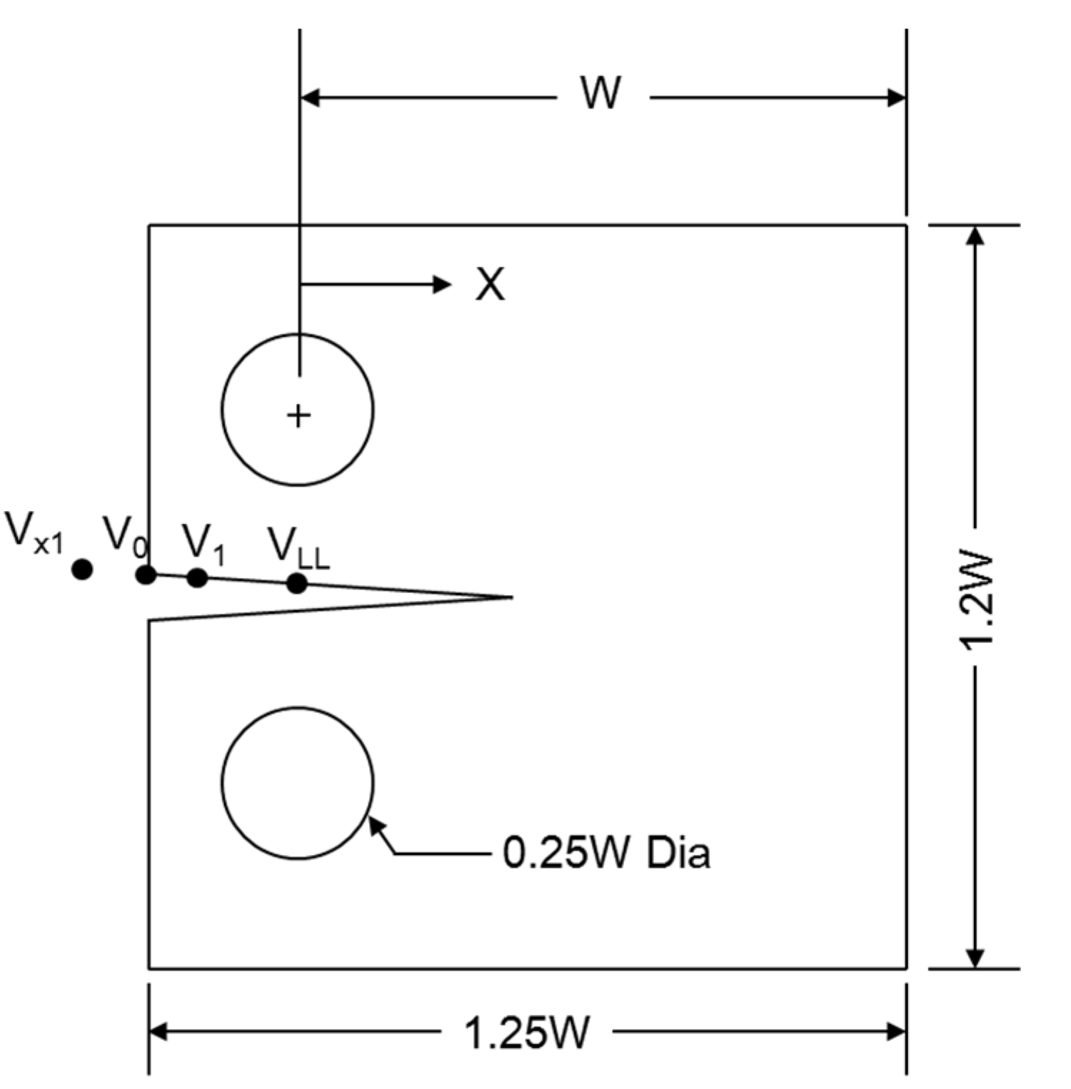
The geometry of the standard CT specimen is shown in
Figure 1 based on ASTM E647 [
37]. Thickness
B and width
W may be varied independently within the following limits. For CT specimens, it is recommended that the thickness be within the range W/20 ≤
B ≤ W/4. Specimens having thicknesses up to and including W/2 may also be employed.
Figure 1.
Geometry of the test specimen [
37].
The fatigue precrack is made in the specimen using the
K (stress intensity factor)-decreasing procedure based on ASTM E647 [
37].
K-decreasing procedure requires that the final
Kmax during precracking shall not exceed the initial
Kmax for which test data are to be obtained. Therefore, forces corresponding to higher
Kmax values used to initiate cracking at the machined notch and the force range shall be stepped-down.
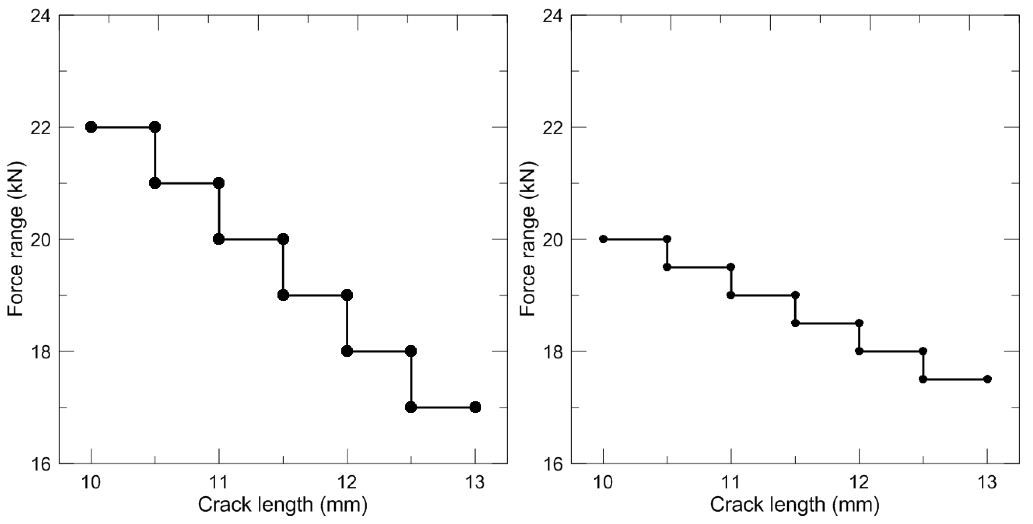
Figure 2 shows the actual stepped-down force histories for precracking according to
K-decreasing procedure. The frequency of fatigue loading is 10 Hz. The initial
Kmax and final
Kmax during the
K-decreasing procedure at both the room temperature and the cryogenic temperature are 34.44 and 31.64 MPa
and 32.57 and 31.31 MPa
, respectively.
Figure 2.
Actual K-decreasing by stepped force shedding at room temperature (left) and cryogenic temperature (right).
2.2. Test Facilities
Servo-hydraulic testing machines with a maximum load capacity of ±50 tons (IST-8800) were used for the fatigue crack growth rate test of 7% nickel steel. To maintain the cryogenic temperature, a special-purpose cryogenic chamber was fabricated and installed in the testing machine.
All the tests were terminated at the point where a through-width fracture occurred. A load control mode was used a 10 Hz as same as precracking procedure. The maximum loads of 18 kN are applied to specimens tested at both the room temperature and the cryogenic temperature. The stress ratios are zero for both tests.
2.4. Test Results and Discussion
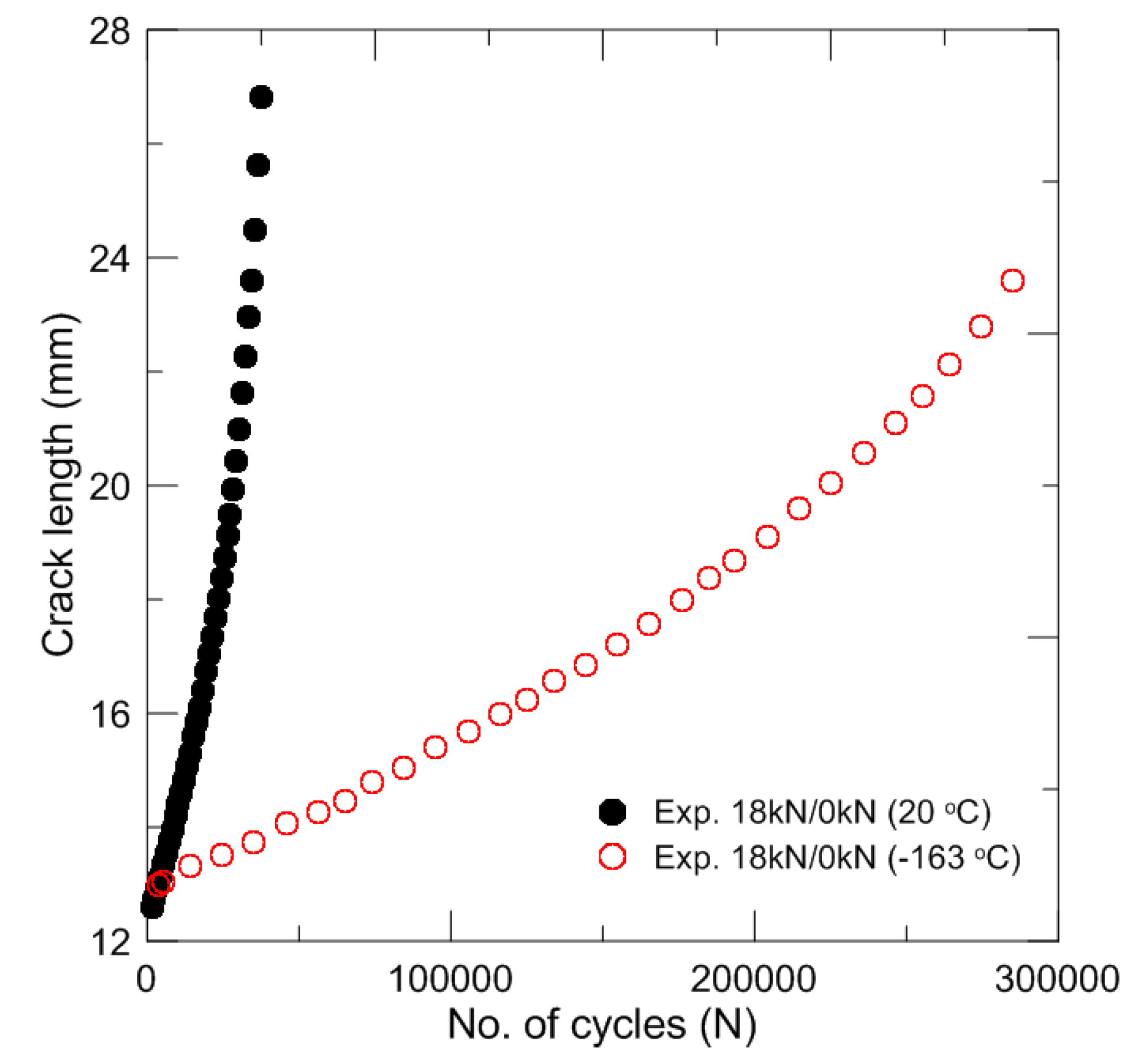
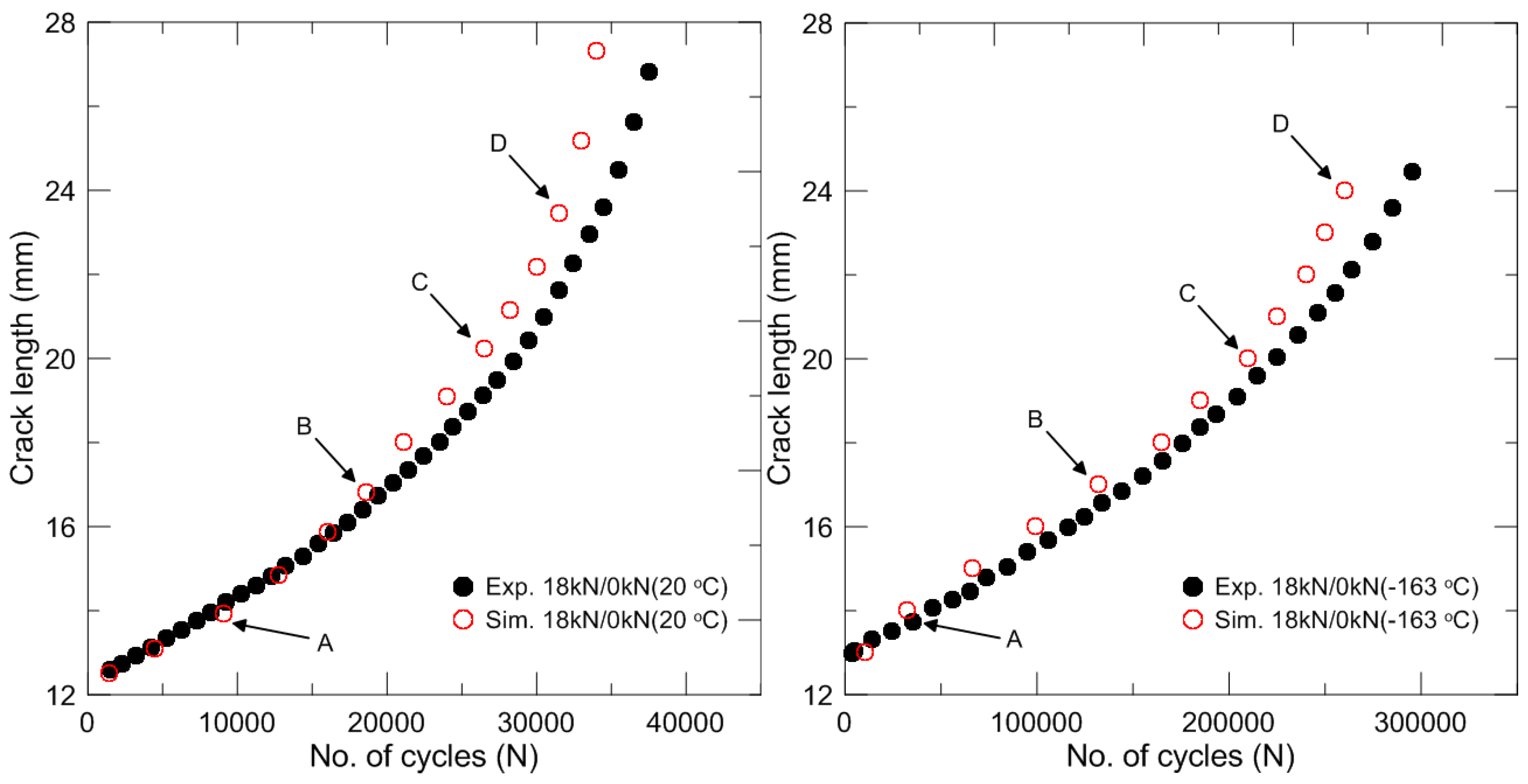
The results of the experimental fatigue crack growth rate tests are shown in
Figure 4 and
Figure 5. The test results at both temperatures are presented together.
Figure 4 shows the relationship between the number of cycles and the crack length. As shown in the figure, 7% nickel steel exhibits enhanced fracture resistance under fatigue loading at cryogenic temperature.
Figure 4.
Relationship between the crack length and the number of cycles at the room and cryogenic temperatures.
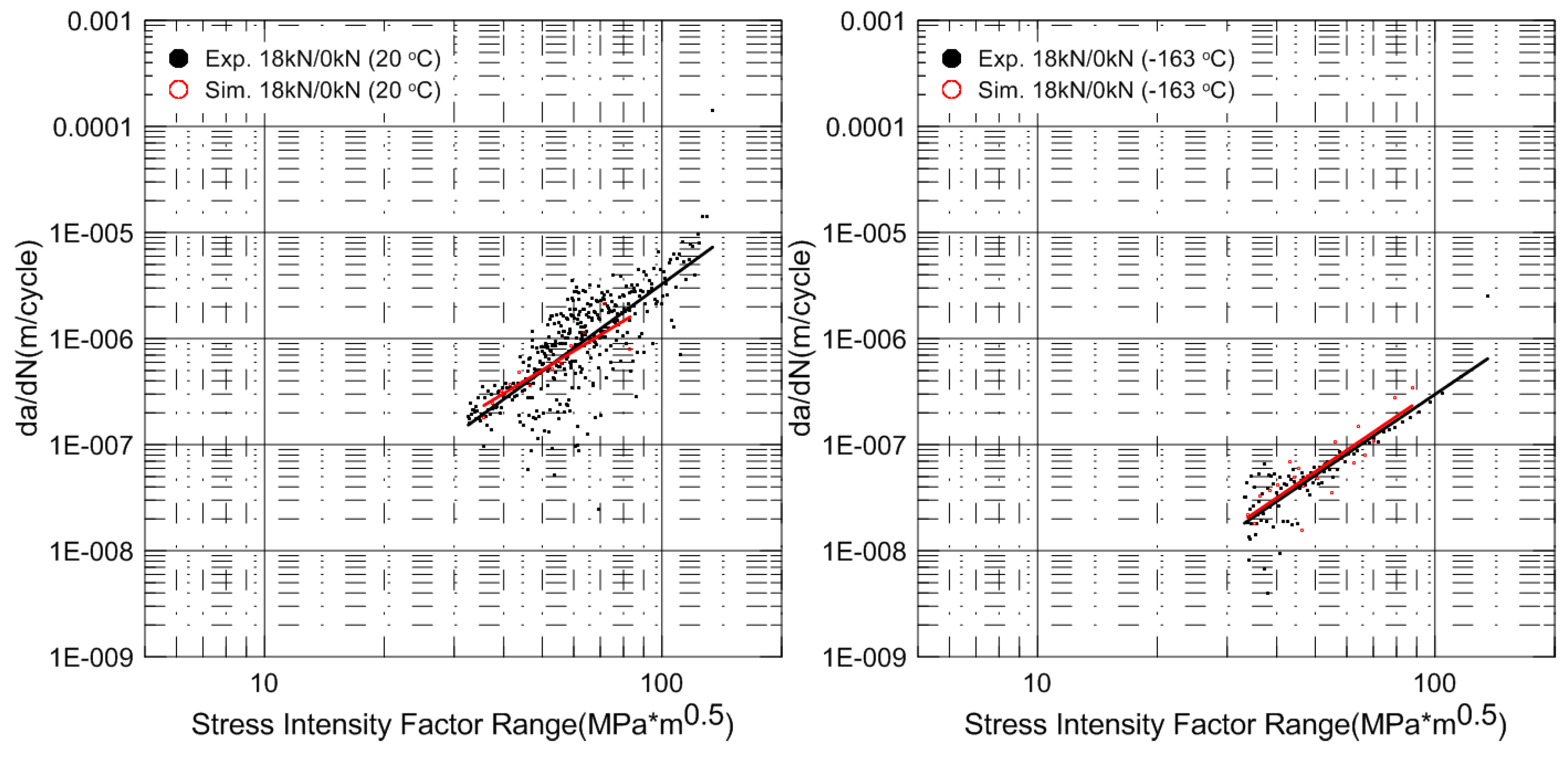
Figure 5 shows a log-log plot of the relationship between d
a/d
N and ∆
K. The material parameters in terms of Paris’ law,
C and
m, are determined from this result. The experimental fatigue crack growth rate test results, including the material parameters
C and
m, are summarized in
Table 3.
Figure 5.
Relationship between da/dN and ∆K at room and cryogenic temperatures.
Table 3.
Summary of experimental fatigue crack growth rate test results.
| Material | Temperature | Max. Load (kN) | Min. Load (kN) | Cycle (Nf) | C | m |
|---|
| 7% Ni | RT | 18 | 0 | 40,019 | 2.17 × 10⁻¹¹ | 2.57 |
| CT (−163 °C) | 18 | 0 | 349,541 | 21.61 × 10⁻¹² | 2.71 |
In the present study, d
a/d
N and ∆
K curves are obtained from two neighboring points of experimental results as follows:
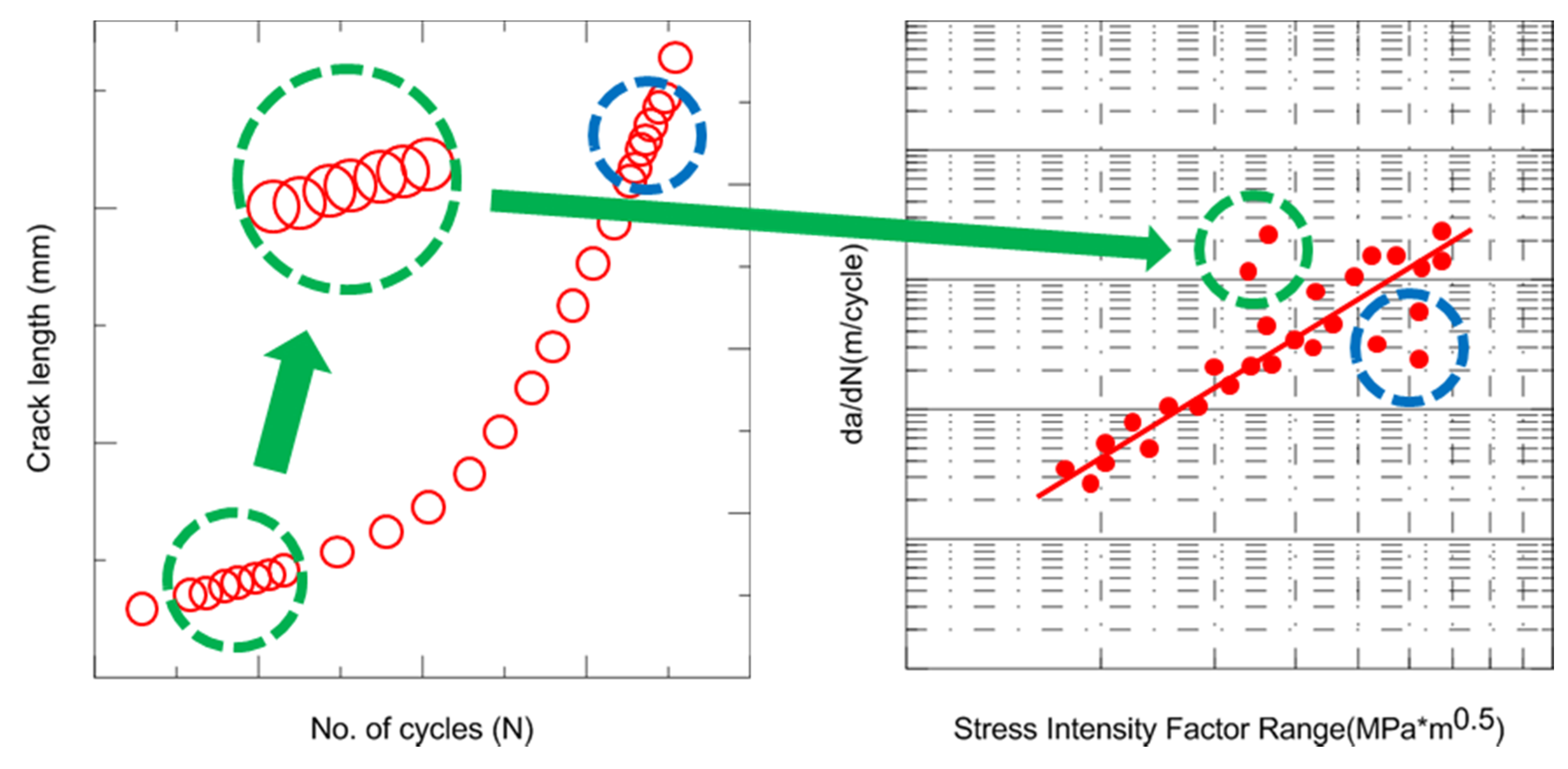
In
Figure 5, scatters are presented around a line representing Paris’ Law. The large scatter is explained by
Figure 6. Here, assuming that the two neighboring points shown in the green-outlined section in the left frame have almost the same crack length (
i.e., ∆
K, a function of ∆
P and the crack length, is almost the same) at different numbers of cycles, the related point in the graph of d
a/d
N with respect to ∆
K is located in the green-outlined section in the right frame. As in the previous case, if the two neighboring points have different crack lengths at almost the same number of cycles, scatters appear in
Figure 6 (blue-outlined section). The fatigue crack is not propagated at every cycle during the experiments. Therefore, some scatters in
Figure 5 are negligible in view of the total fatigue-crack propagation during the FCGR tests, and the relationship between the crack length and number of cycles represented in
Figure 4 is not affected by the scatters in
Figure 5.
Figure 6.
Schematics of scatters induced on da/dN − ∆K curve.
As shown in the test results, the fracture resistances of 7% nickel steel under fatigue loading are considerably different between room temperature and cryogenic temperature (see
Figure 4). Retained austenite is known to improve the toughness and strength of steels such as nickel-alloyed steels including austenitic stainless steels [
35,
36,
38]. The nickel decreases the temperature of the martensite transformation and thermally stabilizes the austenite. Retained austenite enhances the fracture toughness by strain-induced martensite transformation within the temperature range of room temperature to 70 K. Increasing the content of retained austenite strengthens the effect of the strain-induced martensite transformation and thereby elevates the fracture toughness. Notably, these results indicate that both the composition and microstructure can influence low-temperature strengthening mechanisms [
39,
40]. These phenomena reveal the importance of understanding material nonlinearities, such as temperature dependency, which result in an increased fracture-resistance capacity.
The details of the fatigue crack growth test render it difficult to perform at a low temperature. The reasons for this include the special equipment required, the special care necessary for data acquisition, the cost, and the time needed. However, prior to the industrial utilization of a new type of material, the evaluation of the fracture resistance capacity under fatigue loading is essential for safe design. Therefore, a low-cost, efficient test method is required, particularly for low-temperature conditions.
3. Coupling Damage Analysis for Computational FCGR Tests
In the present study, a method for computationally estimating the fatigue crack growth rate was proposed based on a structural damage analysis using FEA. Generally, it is known that there are two types of representative approaches for applying damage variables in conjunction with internal state variables such as the stress and strain to predict the failure of a structure: fully coupled and uncoupled approaches [
36].
In an uncoupled approach, the failure prediction of a structure is carried out using a threshold value for the damage, and the damage variable is calculated using a damage evolution equation, with the stress fields obtained from a structural analysis. Although an uncoupled approach is relatively comfortable and can save calculation time, this approach cannot ensure precise results because there is no coupling between the strain and damage field during the structural analysis [
17,
41,
42].
In a fully coupled approach, the damage variable is calculated using a damage evolution equation during a structural analysis, and the stress, strain, and damage fields are mutually affected. Therefore, the full coupling process produces more accurate results, but it requires a relatively large amount of time for the calculation, which is conducted throughout the entire FEA process [
17,
41,
42].
The proposed computational method for estimating the fatigue crack growth rate (FCGR) was carried out by adopting both approaches in computational FCGR tests. A fully coupled analysis was primarily performed during the computational tests, and the damage variable was calculated using the material constitutive equation, which included a damage evolution equation. An uncoupled damage analysis was restrictively performed between the fully-coupled analyses of stable regions of the damage evolution.
3.1. Fully-Coupled Analysis: Damage-Coupled Constitutive Model
In this study, the Bodner-Partom material model was employed as a material constitutive model for the computational fatigue crack growth rate evaluation of 7% nickel steel [
18]. This model is an elastic-viscoplastic model describing rate-dependent plasticity and creep. This means that material behavior is always being modeled as having a certain degree of inelasticity. Therefore, the Bodner-Partom material model is recognized as a unified viscoplastic model, because it can express the yield phenomenon of materials over a wide range of strain rates and temperatures quite effectively, despite the absence of yield functions. This distinguishing feature is intended so that the overall framework expressing the macroscopic response properties, such as strain rate sensitivity and temperature dependency, are consistent with the essential physics of elastic and inelastic deformation. Therefore, this model was developed in the form of macroscopic equations, and specific microscopic mechanisms were not necessary. The employed viscoplastic model is described as in the following [
18].
where
,
and
are the total strain, the elastic strain and the plastic strain rate tensor, respectively.
D0 is the assumed maximum plastic strain rate,
Z is the total hardening variable, and
n is the material parameter that controls the rate sensitivity. σ
eff is the effective stress. The total hardening variable is defined as follows:
where
Z0 and
Z1 are the initial and saturated values of the isotropic hardening variable, respectively;
mh is the rate of isotropic hardening; and
WP is the plastic work. σ
ij is the stress tensor.
Generally, a two-scale damage model is adopted for expressing material degradation under high-cycle fatigue loading [
21,
43,
44,
45]. The two-scale damage model is based on the notion that initiation and evolution of the damage in brittle fractures and high-cycle fatigue fractures are governed by plastic deformation in a microscopic region of a material [
21]. A two-scale damage model includes a scale transition law that links the mesoscopic and microscopic scales. Therefore, a large number of experiments are required to define a scale transition law and determine the internal state variable in a microscopic region, such as accumulated plastic strain.
In this study, a Bodner-Chan damage model was used to express the material degradation and crack growth of 7% nickel steel during the simulation of crack growth under high-cycle fatigue loading [
18]. Instead of the two-scale damage model, rearrangement of the critical damage was adopted for the material degradation under high-cycle fatigue loading. As previously mentioned, the damage-coupled constitutive model employed in this study is always modeled as having a certain degree of plasticity. This feature is effective for expressing material failure under high-cycle fatigue. A scale for rearrangement of the critical damage was obtained from some simulations described in
Section 4.2.
The viscoplastic model described above was incorporated in the damage model expressed below [
18]:
where ω is the damage parameter which is the material internal state variable and
Sij is the deviatoric stress tensor.
b and
h are the material parameters that control the characteristics of damage, and
is the multiaxial stress function proposed by Hayhurst and Leckie [
46].
, σ
eff, and
are the maximum tensile principal stress, effective stress, and first stress invariant, respectively.
C1,
C2,
C3 and
r are constants of the material, such that
C1 +
C2 +
C3 = 1.
3.2. Uncoupled Analysis: Jump-in-Cycles Procedure
In the present study, the jump-in-cycles procedure is adopted to calculate fatigue damage in order to reduce the computation time. This procedure can be classified with the uncoupled method in structural damage analysis [
19]. The jump-in-cycles procedure is a method to “jump” full blocks of
cycles in a damage calculation based on the postulation that damage accumulation is progressed linearly in the stable region of damage accumulation.
is expressed as follows:
where
is the blocks of number of cycles, and
is the accumulated damage for the jumped blocks.
is also a given value that determines the accuracy of the procedure.
(
is the critical damage) is a good compromise between accuracy and time cost [
19].
NS is a stabilized cycle, and
is the accumulated damage increment over this single cycle. The accumulated damage is updated as
3.3. Algorithm for Computational FCGR Tests
As mentioned previously, computational method for FCGR tests based on damage-coupled FEA is comprised of fully coupled and uncoupled approaches coped with material constitutive model and jump-in-cycles procedure, respectively. Each of procedures for analysis was implemented into ABAQUS user defined subroutine UMAT and algorithm for mutual calculation of damage accumulation from fully and uncoupled analyses was carried out. UMAT is well known that the commercial FE code ABAQUS allows the definition of the material state at every integration point within the FE element. In this regard, the ABAQUS user-defined subroutine UMAT is commonly used to implement a specific constitutive model in the finite element analysis. This can give a significant improvement in the FE analysis results, especially if there is no adequate material model within the ABAQUS libraries.
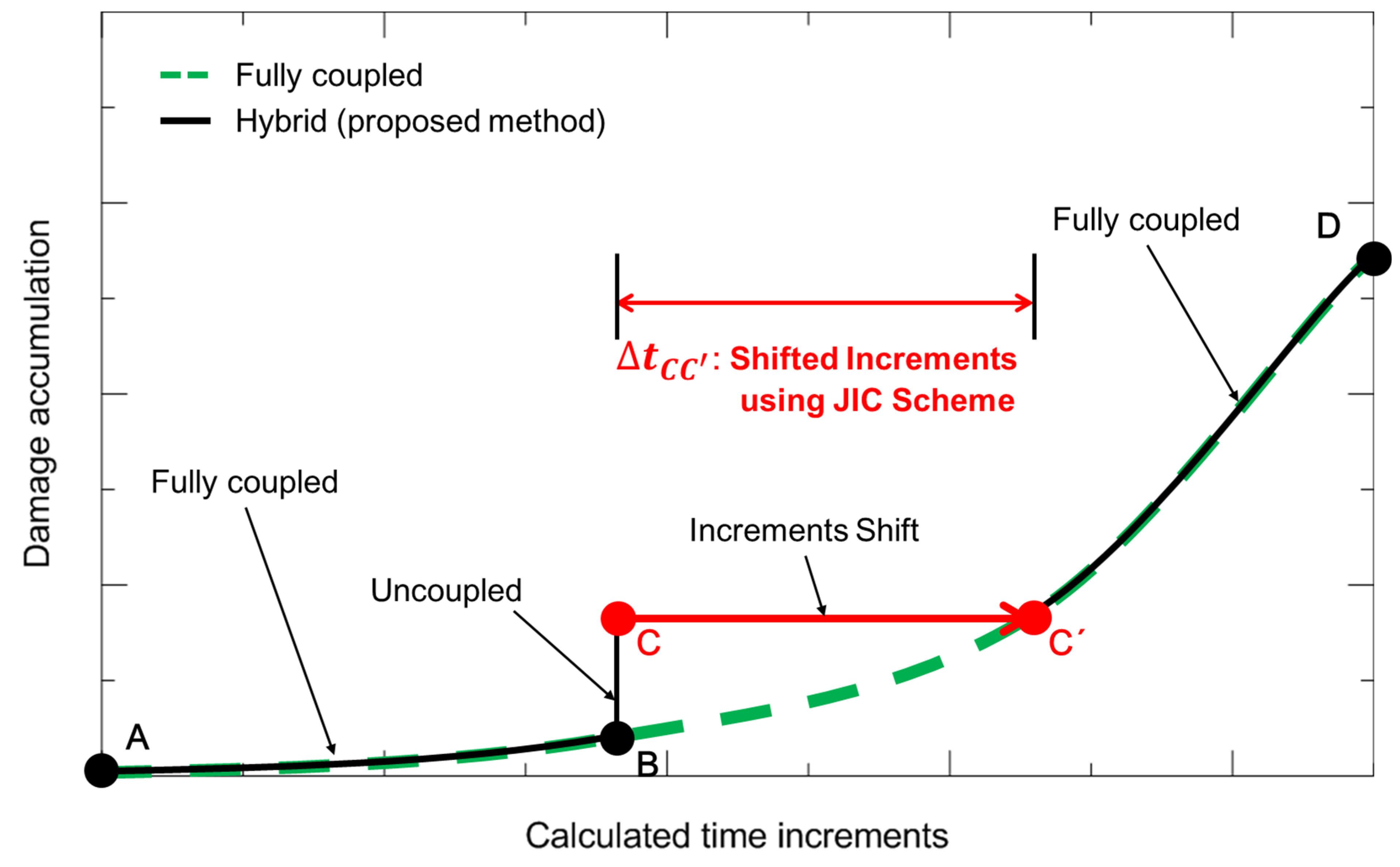
Figure 7 shows a schematic of the accumulated damage during the fatigue analysis using the proposed method comprised of the fully and uncoupled damage analyses (hereafter referred to as the “hybrid method”). First, the fatigue damage was calculated using the fully coupled approach (using the damage-coupled material constitutive model). This process was relevant to the section from point A to point B in
Figure 7. If the damage accumulation calculated by the damage-coupled material constitutive model was stable at point B, the jump-in-cycles procedure was conducted, and the accumulated damage was updated as point C, as follows:
where
is the accumulated damage during jump-in-cycles procedure and
is calculated by
where
is the jumped blocks of number of cycles for the accumulation of damage updated by the jump-in-cycles procedure. In other words,
is the saved computation time (number of cycles) for the fatigue damage analysis. This uncoupled approach to the damage analysis is relevant to the section from point B to point C shown in
Figure 7. Subsequently, the time increment is shifted to point C' from point C, and the uncoupled process is terminated. As shown in
Figure 7,
is the shifted time increment that resulted from the jump-in-cycles procedure, and this parameter is the other value along with
. This was because the fatigue damage analysis was performed in the real-time domain rather than using the number of cycles. In this study, the adopted damage-coupled constitutive model was formulated based on the real-time domain.
and
represented the saved number of cycles and saved time increments, respectively. When a
value obtained from the jump-in-cycles procedure was 1000 cycles, there was a 100 s time increment shift in the structural analysis (assuming a time increment of 0.1 s was required for the structural analysis for a 1-cycle load). Finally, in the section from point C' to point D, the fatigue damage was again calculated based on the damage-coupled material constitutive model. The systematic process for fatigue damage analysis proposed here can be briefly summarized as follows: (1) fully coupled analysis; (2) uncoupled analysis; (3) increment shift; and (4) fully coupled analysis again.
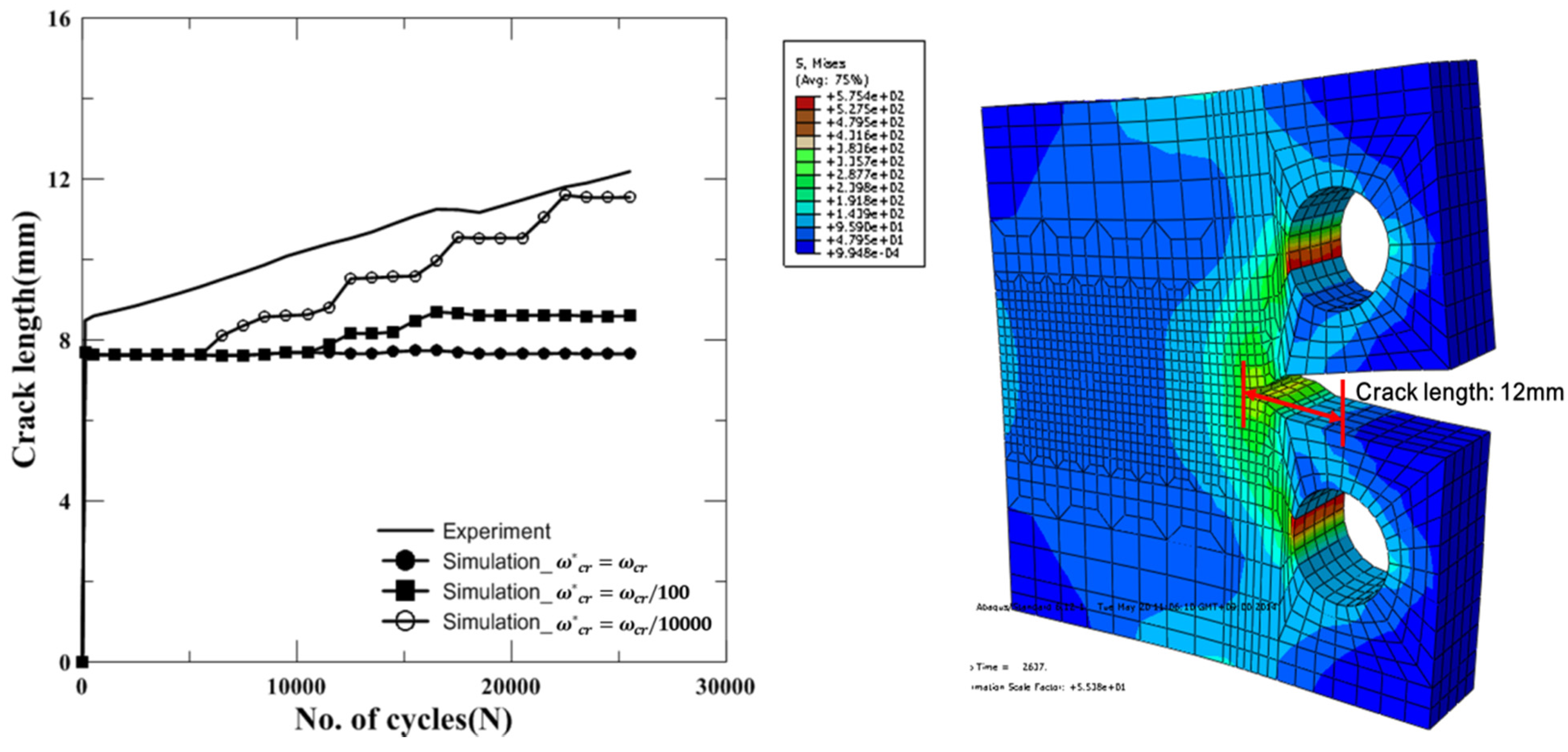
In the present study, the parameter was predetermined to calculate the accumulated damage by the jump-in-cycles procedure because the ratio of the accumulated damage increment and the increment in the number of cycles in the stable region was difficult to obtain numerically. Therefore, and were predetermined, and the value of was checked using . In the present study, values of 1000 and 10,000 cycles were used at room and cryogenic temperatures, respectively. The increment used for the number of cycles in the stable region was 100 cycles for both temperatures. It was postulated that the stable regions appeared when the accumulated damage reached 1.0 × 10⁻¹⁰ and 1.0 × 10⁻²⁰ in the room and cryogenic temperature cases, respectively.
Figure 7.
Schematic of accumulated damage under fatigue analysis using proposed method comprised with fully and uncoupled damage analysis approaches.
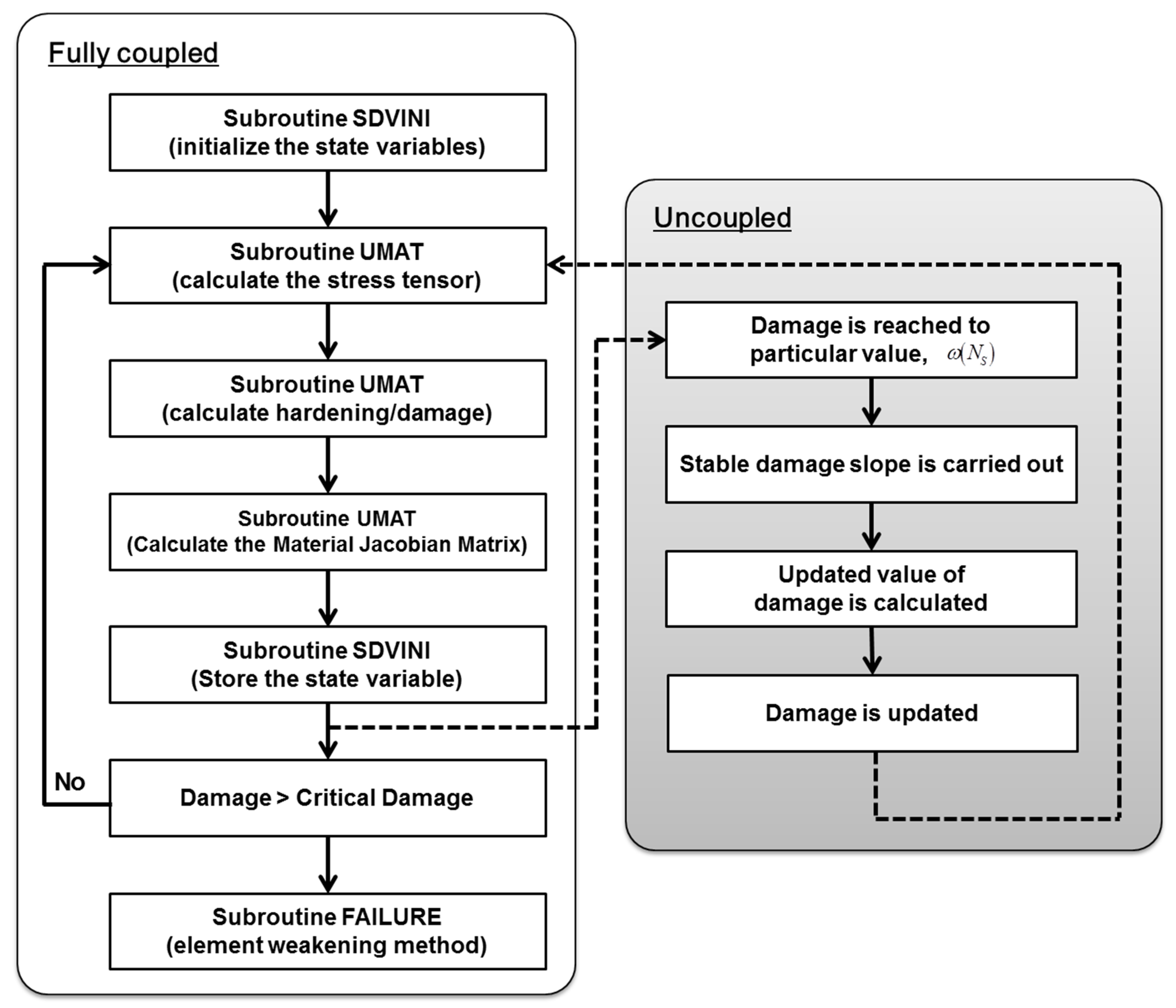
The aforementioned process for calculating the accumulated damage using jump-in-cycles procedure was implemented into ABAQUS user defined subroutine UMAT and damage-coupled material constitutive model classified as a fully coupled approach was also implemented into ABAQUS UMAT. The computational algorithm of UMAT for FCGR test simulation is presented in
Figure 8. The most of times for structural damage analysis is carried out using the fully coupled method based on a damage-coupled constitutive model. The jump-in-cycles procedure is used as an uncoupled method for reducing the computation time. The jump-in-cycles procedure for damage analysis was already adopted in the author’s previous study and was verified for calculating the high cycle fatigue damage, although fatigue analyses were carried out using PATRAN/NASTRAN [
17].
The implicit formulation of the damage-coupled constitutive model is also carried out and implemented into ABAQUS UMAT. All of these incremental values and the damage parameter ω must be updated in the calculation procedure by the definition of the solution-dependent state variables (SDVs). SDVs are initialized in the subroutine SDVINI of ABAQUS. The value of ω progressively increases, and the subroutine FAILURE is called to reduce the corresponding element stiffness when ω reaches the predetermined critical value ωcr.
Figure 8.
Computational algorithm of UMAT for FCGR test simulation.
The optimal time increment ∆
t and the corresponding strain increment, which are computed at the end of the previous time increment, are determined using the Jacobian matrix. The numerical integration scheme used in the present study is described below. The incremental strain is given by
The corresponding elastic trial stress tensor is computed from
where
Dijkl is the elastic stiffness tensor. The updates of the stresses can then be obtained from
where
is the plastic multiplier. The scalar ∆λ, defined by ∆λ = λ∆
t, can be calculated on the basis of the damage using
At the end of the increment, the time history values of each solution-dependent state variable are stored using the STATEV array. The following equations are representative state variables of the constitutive equation:


 ,
, 