<?xml version="1.0" encoding="UTF-8"?>
<!DOCTYPE article PUBLIC "-//NLM//DTD Journal Publishing DTD v2.3 20070202//EN" "journalpublishing.dtd">
<article xmlns:mml="http://www.w3.org/1998/Math/MathML" xmlns:xlink="http://www.w3.org/1999/xlink" xml:lang="en" article-type="research-article">
  <front>
    <journal-meta>
      <journal-id journal-id-type="publisher-id">metals</journal-id>
      <journal-title>Metals</journal-title>
      <abbrev-journal-title abbrev-type="publisher">Metals</abbrev-journal-title>
      <abbrev-journal-title abbrev-type="pubmed">Metals</abbrev-journal-title>
      <issn pub-type="epub">2075-4701</issn>
      <publisher>
        <publisher-name>MDPI</publisher-name>
      </publisher>
    </journal-meta>
    <article-meta>
      <article-id pub-id-type="doi">10.3390/met2020143</article-id>
      <article-id pub-id-type="publisher-id">metals-02-00143</article-id>
      <article-categories>
        <subj-group>
          <subject>Article</subject>
        </subj-group>
      </article-categories>
      <title-group>
        <article-title>Influence of Nickel Particle Reinforcement on Cyclic Fatigue and Final Fracture Behavior of a Magnesium Alloy Composite</article-title>
      </title-group>
      
      <contrib-group>
        <contrib contrib-type="author">
          <name>
            <surname>Srivatsan</surname>
            <given-names>Tirumalai S.</given-names>
          </name>
          <xref rid="af1-metals-02-00143" ref-type="aff">1</xref>
          <xref rid="c1-metals-02-00143" ref-type="corresp">*</xref>
        </contrib>
        <contrib contrib-type="author">
          <name>
            <surname>Manigandan</surname>
            <given-names>K.</given-names>
          </name>
          <xref rid="af2-metals-02-00143" ref-type="aff">2</xref>
        </contrib>
        <contrib contrib-type="author">
          <name>
            <surname>Godbole</surname>
            <given-names>Chinmay</given-names>
          </name>
          <xref rid="af1-metals-02-00143" ref-type="aff">1</xref>
        </contrib>
        <contrib contrib-type="author">
          <name>
            <surname>Paramsothy</surname>
            <given-names>Muralidharan</given-names>
          </name>
          <xref rid="af2-metals-02-00143" ref-type="aff">2</xref>
        </contrib>
        <contrib contrib-type="author">
          <name>
            <surname>Gupta</surname>
            <given-names>Manoj</given-names>
          </name>
          <xref rid="af2-metals-02-00143" ref-type="aff">2</xref>
        </contrib>
      </contrib-group>
      <aff id="af1-metals-02-00143"><label>1 </label>Division of Materials Science and Engineering, Department of Mechanical Engineering, The University of Akron, Akron, OH 44309, USA; Email: <email>chinmaygodbole@gmail.com</email></aff>
      <aff id="af2-metals-02-00143"><label>2 </label>Department of Mechanical Engineering, National University of Singapore, Singapore 117-576, Singapore; Email: <email>mk77@zips.uakron.edu</email> (K.M.); <email>mpemp@nus.edu.sg</email> (M.P.); <email>mpegm@nus.edu.sg</email> (M.G.)</aff>
      <author-notes>
        <corresp id="c1-metals-02-00143"><label>*</label> Author  to whom correspondence should be addressed; Email: <email>tsrivatsan@uakron.edu</email>; Tel.: +13-309-726-196; Fax: +13-309-726-027.</corresp>
      </author-notes>
      <pub-date pub-type="epub">
        <day>07</day>
        <month>06</month>
        <year>2012</year>
      </pub-date>
      <pub-date pub-type="collection"><month>06</month>
        <year>2012</year>
      </pub-date>
      <volume>2</volume>
      <issue>2</issue>
      <fpage>143</fpage>
      <lpage>169</lpage>
      <history>
        <date date-type="received">
          <day>12</day>
          <month>04</month>
          <year>2012</year>
        </date>
        <date date-type="rev-recd">
          <day>25</day>
          <month>05</month>
          <year>2012</year>
        </date>
        <date date-type="accepted">
          <day>29</day>
          <month>05</month>
          <year>2012</year>
        </date>
      </history>
      <permissions>
        <copyright-statement>©  2012 by the authors; licensee MDPI, Basel, Switzerland.</copyright-statement>
        <copyright-year>2012</copyright-year>
        <license xmlns:xlink="http://www.w3.org/1999/xlink" license-type="open-access" xlink:href="http://creativecommons.org/licenses/by/3.0/">
          <p>This article is an open-access article distributed under the terms and conditions of the Creative Commons Attribution license (http://creativecommons.org/licenses/by/3.0/).</p>
        </license>
      </permissions>
      <abstract>
        <p>The microstructure, tensile properties, cyclic stress amplitude fatigue response and final fracture behavior of a magnesium alloy, denoted as AZ31, discontinuously reinforced with nano-particulates of aluminum oxide and micron size nickel particles is presented and discussed. The tensile properties, high cycle fatigue and final fracture behavior of the discontinuously reinforced magnesium alloy are compared with the unreinforced counterpart (AZ31). The elastic modulus and yield strength of the dual particle reinforced magnesium alloy is marginally higher than of the unreinforced counterpart. However, the tensile strength of the composite is lower than the monolithic counterpart. The ductility quantified by elongation to failure over 0.5 inch (12.7 mm) gage length of the test specimen showed minimal difference while the reduction in specimen cross-section area of the composite is higher than that of the monolithic counterpart. At the microscopic level, cyclic fatigue fractures of both the composite and the monolithic alloy clearly revealed features indicative of the occurrence of locally ductile and brittle mechanisms. Over the range of maximum stress and at two different load ratios the cyclic fatigue resistance of the magnesium alloy composite is superior to the monolithic counterpart. The mechanisms responsible for improved cyclic fatigue life and resultant fracture behavior of the composite microstructure are highlighted.</p>
      </abstract>
      <kwd-group>
        <kwd>magnesium alloy</kwd>
        <kwd>particulate reinforcements</kwd>
        <kwd>aluminum oxide</kwd>
        <kwd>nano-size</kwd>
        <kwd>cyclic fatigue</kwd>
        <kwd>fracture</kwd>
      </kwd-group>
    </article-meta>
  </front>
  <body>
    <sec sec-type="intro">
      <title>1. Introduction</title>
      <p>The sustaining need for materials that can be put to use in a spectrum of performance-critical and even non-performance critical applications coupled with their ability to be light in weight and offer beneficial mechanical properties spanning the domains of strength, ductility, toughness, fatigue resistance and even fracture behavior has become both essential and is required in order to facilitate their selection and use for a range of weight-critical applications. This has provided the much needed impetus, interest, incentive and inclination for both material scientists and material engineers to initiate and execute systematic and sustained research efforts with the prime objective of engineering and developing metal-based composites. Commensurate with developing these material there existed a concurrent need for the engineering of effective, efficient and economically viable techniques to process them using laboratory scale infrastructure. Magnesium and its alloys, due to their inherent low density (ρ = 1.74 g cm<sup>3</sup>), are potentially viable and economically affordable candidates for the development of metal matrix composites (MMCs) [<xref ref-type="bibr" rid="B1-metals-02-00143">1</xref>]. In more recent years, since the early 1980s, sustained research and development efforts have been meticulously undertaken with the prime objective of enhancing the mechanical properties of magnesium alloys by selective reinforcement with either ceramic or metallic phases coupled with the use of novel and innovative processing techniques such that the resultant magnesium-based composite offered high specific strength (σ/ρ), high specific stiffness (E/ρ), good damping capacity and importantly the required and essential mechanical properties [<xref ref-type="bibr" rid="B2-metals-02-00143">2</xref>,<xref ref-type="bibr" rid="B3-metals-02-00143">3</xref>,<xref ref-type="bibr" rid="B4-metals-02-00143">4</xref>,<xref ref-type="bibr" rid="B5-metals-02-00143">5</xref>,<xref ref-type="bibr" rid="B6-metals-02-00143">6</xref>].</p>
      <p>The physical properties of the engineered magnesium-based MMCs are based entirely on properties of the key constituents, <italic>i.e.</italic>, the matrix and the reinforcing phase [<xref ref-type="bibr" rid="B3-metals-02-00143">3</xref>,<xref ref-type="bibr" rid="B6-metals-02-00143">6</xref>,<xref ref-type="bibr" rid="B7-metals-02-00143">7</xref>]. The volume fraction, size, shape and distribution of the reinforcing phase, be it particulates, whiskers, or short fibers, do exert a profound influence on both the kinetics and microscopic mechanisms governing the movement of dislocations through the composite microstructure and resultant mechanical behavior of the magnesium-based composite. This finding has in recent years provided the much needed impetus for reinforcing selected few magnesium alloys with hard, brittle and essentially elastically deforming particulates of either a ceramic or metallic phase with the underlying objective of improving mechanical properties to include cyclic fatigue resistance of the matrix alloy [<xref ref-type="bibr" rid="B8-metals-02-00143">8</xref>,<xref ref-type="bibr" rid="B9-metals-02-00143">9</xref>,<xref ref-type="bibr" rid="B10-metals-02-00143">10</xref>,<xref ref-type="bibr" rid="B11-metals-02-00143">11</xref>,<xref ref-type="bibr" rid="B12-metals-02-00143">12</xref>,<xref ref-type="bibr" rid="B13-metals-02-00143">13</xref>,<xref ref-type="bibr" rid="B14-metals-02-00143">14</xref>,<xref ref-type="bibr" rid="B15-metals-02-00143">15</xref>,<xref ref-type="bibr" rid="B16-metals-02-00143">16</xref>]. Over the years, few of the reinforcements that have been tried, studied and whose results have been documented in the “open” literature are silicon carbide [<xref ref-type="bibr" rid="B4-metals-02-00143">4</xref>], particulates of copper [<xref ref-type="bibr" rid="B5-metals-02-00143">5</xref>], titanium carbide [<xref ref-type="bibr" rid="B17-metals-02-00143">17</xref>], and even aluminum oxide [<xref ref-type="bibr" rid="B18-metals-02-00143">18</xref>]. Of the reinforcements that have been tried and successfully used fine particulates of alumina or aluminum oxide (Al<sub>2</sub>O<sub>3</sub>) have engineered both attention and interest among researchers in the pursuit of developing magnesium-based composites [<xref ref-type="bibr" rid="B18-metals-02-00143">18</xref>]. It has also been reported in the published literature that use of nano-sized reinforcements in a magnesium alloy metal matrix promises to exert a beneficial influence on ductility when compared one-on-one with the use of micron-size reinforcements [<xref ref-type="bibr" rid="B10-metals-02-00143">10</xref>,<xref ref-type="bibr" rid="B11-metals-02-00143">11</xref>]. This innovative finding in conjunction with processing-related advancements has provided the much needed incentive for the use of a hybrid reinforcement mixture, <italic>i.e.</italic>, essentially a combination of ceramic and metal, for the magnesium alloy metal matrix so as to complement well with the properties of the reinforcements used. It was felt that the use of a hybrid mixture of reinforcements would help in achieving properties of the material that could not be easily obtained by exclusively using one reinforcement to the metal matrix [<xref ref-type="bibr" rid="B11-metals-02-00143">11</xref>,<xref ref-type="bibr" rid="B16-metals-02-00143">16</xref>,<xref ref-type="bibr" rid="B18-metals-02-00143">18</xref>,<xref ref-type="bibr" rid="B19-metals-02-00143">19</xref>,<xref ref-type="bibr" rid="B20-metals-02-00143">20</xref>].</p>
      <p>For this research study nano-sized aluminum oxide (Al<sub>2</sub>O<sub>3</sub>) particles and fine nickel powder were used as the hybrid reinforcement mixture for a magnesium alloy metal matrix. The resultant composite was synthesized using the technique of Disintegrated Melt Deposition (DMD). In this research paper, the intrinsic influence of nature of the two reinforcements (nano-size Al<sub>2</sub>O<sub>3 </sub>powder and micron-size nickel powder) and the extrinsic influence of processing on microstructural development, tensile properties, cyclic fatigue response under conditions of stress amplitude control and final fracture behavior of the magnesium alloy based metal matrix composite, <italic>i.e.</italic>, AZ31/1.5 vol.% Al<sub>2</sub>O<sub>3</sub>/1.5 vol.% Ni is presented and discussed. To facilitate better understanding of the ceramic (Al<sub>2</sub>O<sub>3</sub>) nanoparticle and metal (nickel) particle reinforcements the test results are compared with the monolithic alloy (AZ31). An examination of the fatigue fracture surfaces of the composite is made to understand and establish the specific role and influence of the dual phase reinforcement in synergism with processing and resultant microstructure on microscopic mechanisms governing cyclic deformation and fracture.</p>
    </sec>
    <sec>
      <title>2. Materials and Processing</title>
      <sec>
        <title>2.1. Materials</title>
        <p>The magnesium alloy used in this research study had a nominal chemical composition, which is summarized in <xref ref-type="table" rid="metals-02-00143-t001">Table 1</xref>. This alloy was provided to the National University of Singapore (NUS, Singapore) by Tokyo Magnesium Company Limited (Yokohama, Japan). Blocks of the as-provided AZ31 alloy were carefully sectioned into smaller pieces and then precision machined to remove any and all oxide layers and other visible scales on the surface. All of the surfaces of the magnesium alloy were washed thoroughly with ethanol subsequent to machining. The alumina particles (Al<sub>2</sub>O<sub>3p</sub>) having a size of 50 nanometers (nm) along with micron-size nickel particles having a size of 44 microns (µm) were used as reinforcements for the AZ31 magnesium alloy to engineer the magnesium alloy-based metal matrix composite. The reinforcing (Al<sub>2</sub>O<sub>3</sub>)<sub>p</sub> particles were procured from Baikowski (Japan) and the reinforcing nickel powder was obtained from Johnson Matthey (USA).</p>
        <table-wrap id="metals-02-00143-t001" position="anchor">
          <object-id pub-id-type="pii">metals-02-00143-t001_Table 1</object-id>
          <label>Table 1</label>
          <caption>
            <p>Nominal chemical composition of Magnesium alloy AZ31.</p>
          </caption>
          <table>
            <thead>
              <tr>
                <th align="center" valign="middle">Element</th>
                <th align="center" valign="middle">Al</th>
                <th align="center" valign="middle">Zn</th>
                <th align="center" valign="middle">Mn</th>
                <th align="center" valign="middle">Si</th>
                <th align="center" valign="middle">Cu</th>
                <th align="center" valign="middle">Ca</th>
                <th align="center" valign="middle">Fe</th>
                <th align="center" valign="middle">Ni</th>
                <th align="center" valign="middle">Others</th>
                <th align="center" valign="middle">Mg</th>
              </tr>
            </thead>
            <tbody>
              <tr>
                <td align="center" valign="middle">Max</td>
                <td align="center" valign="middle">3.5</td>
                <td align="center" valign="middle">1.3</td>
                <td align="center" valign="middle">–</td>
                <td align="center" valign="middle">0.05</td>
                <td align="center" valign="middle">0.05</td>
                <td align="center" valign="middle">0.04</td>
                <td align="center" valign="middle">0.005</td>
                <td align="center" valign="middle">0.10</td>
                <td align="center" valign="middle">0.40</td>
                <td align="center" valign="middle">Balance</td>
              </tr>
              <tr>
                <td align="center" valign="middle">Min</td>
                <td align="center" valign="middle">2.5</td>
                <td align="center" valign="middle">0.7</td>
                <td align="center" valign="middle">0.20</td>
                <td align="center" valign="middle"> </td>
                <td align="center" valign="middle"> </td>
                <td align="center" valign="middle"> </td>
                <td align="center" valign="middle"> </td>
                <td align="center" valign="middle"> </td>
                <td align="center" valign="middle"> </td>
                <td align="center" valign="middle"> </td>
              </tr>
            </tbody>
          </table>
        </table-wrap>
      </sec>
      <sec>
        <title>2.2. Processing</title>
        <sec>
          <title>2.2.1. Magnesium Alloy AZ31</title>
          <p>The technique of disintegrated melt deposition (DMD) [<xref ref-type="bibr" rid="B12-metals-02-00143">12</xref>,<xref ref-type="bibr" rid="B13-metals-02-00143">13</xref>,<xref ref-type="bibr" rid="B14-metals-02-00143">14</xref>,<xref ref-type="bibr" rid="B15-metals-02-00143">15</xref>,<xref ref-type="bibr" rid="B16-metals-02-00143">16</xref>] was used to cast the monolithic alloy. This process essentially required heating the blocks of AZ31 to 750 °C. This heating was accomplished by using resistance heating on a graphite crucible and in an inert atmosphere of argon gas. The graphite crucible had an arrangement for pouring at the bottom. To ensure a near-uniform distribution of the heat, the melt was continuously stirred at 460 rpm for full five minutes. This was made possible using a twin-blade mild steel impeller that had a pitch angle of 45 degrees. To minimize or even avoid interactions between the melt and the mild steel impeller, the impeller was coated with Zirtex 25 (a chemical compound containing 86 pct ZrO<sub>2</sub>, 8.8 pct Y<sub>2</sub>O<sub>3</sub>, 3.6 pct SiO<sub>2</sub>, 1.2 pct K<sub>2</sub>O and Na<sub>2</sub>O with 0.3 pct trace of being inorganic). The molten melt was then released through a 10-mm diameter orifice located at the base of the crucible. At a distance of 265-mm from the pouring point the melt was disintegrated using two jets of argon gas (maintained at a flow rate of 25 L/min) oriented normal to the melt stream. The disintegrated melt slurry was then deposited onto a metallic substrate located 500 mm from the point of disintegration. The deposition resulted in an ingot whose diameter measured 40 mm.</p>
        </sec>
        <sec>
          <title>2.2.2. The Magnesium Alloy Composite (AZ31 + 1.5 vol.% Al<sub>2</sub>O<sub>3</sub> + 1.5 vol.% Ni)</title>
          <p>To form the magnesium alloy composite that contained 1.5 vol. pct alumina (aluminum oxide [Al<sub>2</sub>O<sub>3</sub>]) and 1.5 pct nickel (44 µm size powder), fine powders of both the reinforcing phases, <italic>i.e.</italic>, alumina nano-powder and nickel powder particles, were wrapped together in an aluminum foil having minimum weight (less than 0.5 weight pct) with respect to the magnesium alloy (AZ31). All of the other parameters related to the technique of Disintegrated Melt Deposition (DMD) were essentially unchanged to that used for the monolithic alloy (AZ31).</p>
          <p>Billets of both the monolithic alloy and the dual-phase reinforced composite were precision machined to a size of 35 mm in diameter and subsequently hot extruded on a 150 ton hydraulic press using an extrusion ratio of 20.25. The extrusion was carried out at an elevated temperature of 350 °C. The billets were held at a temperature of 400 °C in a furnace for a period of a full 60 min prior to extrusion. Colloidal graphite was the lubricant chosen and used during extrusion. The rods obtained following extrusion measured 8.0 mm in diameter.</p>
        </sec>
      </sec>
    </sec>
    <sec sec-type="methods">
      <title>3. Experimental Procedures</title>
      <sec>
        <title>3.1. Sample Preparation</title>
        <p>The extruded rods of the monolithic AZ31 alloy and dual particle-reinforced magnesium alloy composite (diameter = 8 mm and length = 300 mm) were precision machined to obtain cylindrical specimens that had threaded ends for use in both uniaxial tension tests and stress-controlled high cycle fatigue tests. The machining was carried out in conformance with specifications outlined in Standard E-8 of American Society for Testing Materials (ASTM) [<xref ref-type="bibr" rid="B21-metals-02-00143">21</xref>]. The major stress axis was taken to be along the extrusion direction of the rod stock. The overall length of the specimen measured 2.3 inches (58 mm) with a diameter of 0.25 inch (6.3 mm) at a thread section and diameter of 0.125 inch (3 mm) at the gage section. The gage length measured 0.5 inch (12.5 mm).</p>
      </sec>
      <sec>
        <title>3.2. Initial Microstructure Characterization</title>
        <p>To understand the specific influence of processing on (a) grain size and shape, and (b) size, shape and distribution of the second-phase particles in the monolithic alloy (AZ31), and (c) the effect of dual particles, <italic>i.e.</italic>, nano-size alumina particulates (Al<sub>2</sub>O<sub>3</sub>) <sub> p </sub>and micron-size nickel powder, reinforcements on intrinsic microstructural features of the magnesium alloy composite, initial microstructural characterization of the as-provided composite material was carried out. No attempt was made in this study to determine the size of the reinforcing Al<sub>2</sub>O<sub>3</sub> particulates dispersed in the magnesium alloy metal matrix. The as-provided extruded rods of the alloy (AZ31) and the composite [AZ31/1.5 vol.%(Al2O3)<sub> P</sub>/1.5 vol.%Ni] were prepared for examination in a light optical microscope (Model: Mitutoyo FS70) and photographed using standard bright field illumination technique. Preparation involved first cutting samples that were perpendicular to the direction of extrusion. The cut samples were then mounted in bakelite. The mounted samples were prepared for optical microscopy observation using standard metallography preparation techniques. Coarse polishing was performed on progressively finer grades (320 grit, 400 grit, and 600 grit) of silicon carbide (SiC) impregnated emery paper. Finish polishing to obtain a mirror-like surface finish was accomplished using 1 micron alumina powder suspended in distilled water as the lubricant. The finish polished samples were then etched using an etchant. The etchant was acetic-picral, <italic>i.e.</italic>, a solution mixture of 5 mL acetic acid, 6 g picric acid, 10 mL water and 100 mL ethanol. The polished surface of the test specimen was subsequently immersed in the etchant till a brown film formed, and then immediately rinsed in running water followed by drying using a hot air gun.</p>
      </sec>
      <sec>
        <title>3.3. Mechanical Testing</title>
        <p>Uniaxial tension tests and stress-controlled high-cycle fatigue tests were performed on a fully automated, close-loop servohydraulic mechanical test machine (Model: INSTRON: 8500 Plus) in a laboratory environment (Relative Humidity of 55 pct) and at room temperature (25 °C). The servohydraulic machine was equipped with a 22 kip (100 KN) load cell and the tensile tests were performed at a constant strain rate of 0.0001 per second. A PC-based Data <bold>A</bold>cquisition <bold>S</bold>oftware (DAS) was used to record the stress and strain measurements during the monotonic tension test.</p>
        <p>The stress amplitude-controlled high cycle fatigue tests were performed on both the monolithic alloy (AZ31) and the composite (AZ31/1.5 vol.% Al<sub>2</sub>O<sub>3</sub>/1.5 vol.% Ni) using a sinusoidal waveform and at stress ratios (R = minimum stress/maximum stress) of 0.1 and 1.0. The tests were conducted at a constant frequency of 5 Hz with the objective of establishing the variation of maximum stress (σ<sub>maximum</sub>) with cyclic fatigue life (N<sub>f</sub>). Under stress amplitude controlled fatigue testing the maximum stress was taken to be a fraction of the yield stress of the candidate material as obtained from the uniaxial tension test. The number of cycles to cause complete failure or separation is taken as the fatigue life (N<sub>f</sub>).</p>
      </sec>
      <sec>
        <title>3.4. Failure-Damage Analysis</title>
        <p>A high magnification Scanning Electron Microscope (Model: FEI Quanta 200) was used to examine the fracture surfaces of the deformed and failed fatigue specimens. Observations were made over a range of magnifications to identify the macroscopic fracture mode and to concurrently establish the microscopic features and intrinsic mechanisms causing failure. Samples for observation were obtained from the fully deformed and failed fatigue test specimens by sectioning parallel to the fracture surface.</p>
      </sec>
    </sec>
    <sec sec-type="results">
      <title>4. Results and Discussion
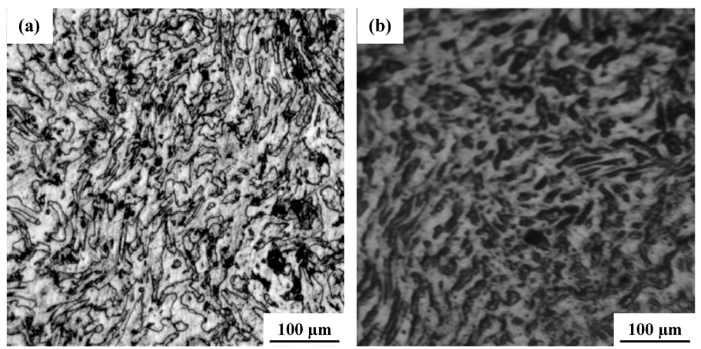
</title>
      <sec>
        <title>4.1. Microstructure</title>
        <p>The optical microstructures of the monolithic alloy AZ31 and the dual particle, <italic>i.e.</italic>, nanosize alumina particle and micron-sized nickel powder, reinforced composite were taken using bright a field illumination technique and are shown in <xref ref-type="fig" rid="metals-02-00143-f001">Figure 1</xref>. Both the unreinforced alloy and the reinforced magnesium alloy or composite revealed a poly-grained structure but with an observable difference in their microstructural features or microstructural intricacies. The dual particle reinforced magnesium alloy composite (<xref ref-type="fig" rid="metals-02-00143-f001">Figure 1</xref>b) revealed an observable difference in intrinsic microstructural features when compared one-on-one to the monolithic counterpart (<xref ref-type="fig" rid="metals-02-00143-f001">Figure 1</xref>a). Most noticeable was the difference in both size and volume fraction of the two phases, <italic>i.e.</italic>, the primary phase (the matrix) and the second phase (the eutectic). No attempt was made in this study to determine both the size and volume fraction of the phases present in the monolithic alloy and the dual particle reinforced magnesium alloy composite. The observed difference in intrinsic microstructural features of the dual particle-reinforced magnesium alloy composite is ascribed to the mutually interactive influences of the following competing mechanisms:</p>
        <list list-type="simple">
          <list-item>
            <p>(1) A high extrusion temperature of 350 °C (T = 0.675 T<sub>M</sub>), resulting in conditions conducive to the occurrence of dynamic recrystallization.</p>
          </list-item>
          <list-item>
            <p>(2) The presence of a near uniform dispersion of the two reinforcing phases, <italic>i.e.</italic>, nanosize alumina particles and micron-size nickel powder, which act as potential sites that favor heterogeneous nucleation during solidification. This was made possible by minimizing gravity-related segregation due to a proper selection of the stirring parameters during processing of the composite [<xref ref-type="bibr" rid="B12-metals-02-00143">12</xref>].</p>
          </list-item>
        </list>
        <fig id="metals-02-00143-f001" position="anchor">
          <label>Figure 1</label>
          <caption>
            <p>Optical micrographs showing the undeformed microstructure of : (<bold>a</bold>) alloy AZ31 and (<bold>b</bold>) alloy AZ31 reinforced with nano Al<sub>2</sub>O<sub>3</sub>particulates and micron size nickel powder particles.</p>
          </caption>
          <graphic xmlns:xlink="http://www.w3.org/1999/xlink" xlink:href="metals-02-00143-g001.tif"/>
        </fig>
        
        <p>The monolithic alloy (AZ31) revealed a duplex microstructure consisting of light colored alpha (α) phase and the dark colored eutectic phase (β), which was found to be distributed both at and along the grain boundaries (<xref ref-type="fig" rid="metals-02-00143-f001">Figure 1</xref>a). The alumina nanoparticulate and nickel particle reinforced magnesium alloy revealed a heterogeneous distribution of the reinforcing nickel particles through the microstructure with pockets of particle agglomeration resulting in nickel-particle-rich and nickel-particle-depleted regions (<xref ref-type="fig" rid="metals-02-00143-f001">Figure 1</xref>b). Earlier studies have used the technique of X-ray diffraction and identified the eutectic phase (β) to be the intermetallic particle (Mg<sub>17</sub>Al<sub>12</sub>) [<xref ref-type="bibr" rid="B22-metals-02-00143">22</xref>,<xref ref-type="bibr" rid="B23-metals-02-00143">23</xref>]. An observable higher volume fraction of the eutectic phase (β) was observed in the reinforced magnesium alloy when compared one-on-one with the unreinforced counterpart (<xref ref-type="fig" rid="metals-02-00143-f001">Figure 1</xref>a). However, no attempt was made in this study to determine the volume fraction of the phases present in the two materials, <italic>i.e.</italic>, monolithic alloy and the composite. The influence of an increased volume fraction of the eutectic phase on the tensile properties and high cycle fatigue resistance is discussed in the following section.</p>
      </sec>
      <sec>
        <title>
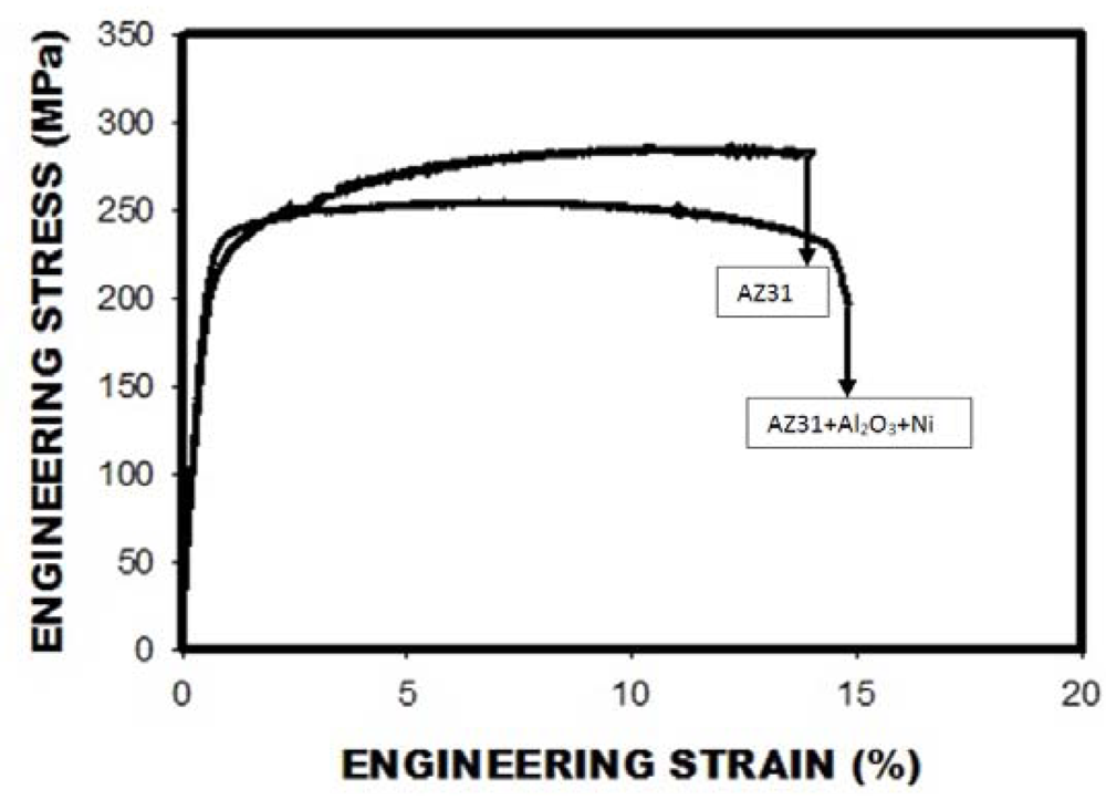
4.2. Tensile Properties</title>
        <p>The uniaxial tensile properties of this dual particle reinforced magnesium alloy composite along with the monolithic or unreinforced matrix alloy (AZ31) are summarized in <xref ref-type="table" rid="metals-02-00143-t002">Table 2</xref>. The values recorded are the mean values based on duplicate tests. An attempt is made to understand the synergistic and mutually interactive influences of the two reinforcing particles in governing the fine microscopic mechanisms and the resultant macroscopic mechanical behavior of the magnesium alloy composite under uniaxial loading. This enables us to make the following observations from the test results.</p>
        <list list-type="simple">
          <list-item>
            <p>(1) Only a seven percent increase was found in the Young’s Modulus [E] of the AZ31/1.5 vol.% Al<sub>2</sub>O<sub>3</sub>/Ni composite when compared to the monolithic alloy AZ31.</p>
          </list-item>
          <list-item>
            <p>(2) A five percent increase was found in the yield strength of the dual particle reinforced magnesium alloy composite when compared to the monolithic alloy (AZ31).</p>
          </list-item>
          <list-item>
            <p>(3) The ultimate tensile strength of the nickel particle reinforced magnesium alloy composite was 15 pct lower than the monolithic unreinforced (AZ31) counterpart.</p>
          </list-item>
          <list-item>
            <p>(4) The dual particle reinforced magnesium alloy based composite showed hardly any change in elongation to failure but a 45 pct-increase in reduction-in-cross-sectional area (RA = 23.7 pct) when compared one-on-one with the monolithic counterpart (AZ31) [RA = 16.4 pct].</p>
          </list-item>
        </list>
        <table-wrap id="metals-02-00143-t002" position="anchor">
          <object-id pub-id-type="pii">metals-02-00143-t002_Table 2</object-id>
          <label>Table 2</label>
          <caption>
            <p>Room temperature tensile properties of the candidate materials. (Values are the mean based on duplicate tests).</p>
          </caption>
          <table>
            <thead>
              <tr>
                <th rowspan="2" align="center" valign="middle">Specimen</th>
                <th colspan="2" align="center" valign="middle">Elastic Modulus</th>
                <th colspan="2" align="center" valign="middle">Yield Strength</th>
                <th colspan="2" align="center" valign="middle">UTS</th>
                <th align="center" valign="middle">Elongation GL = 0.5"</th>
                <th align="center" valign="middle">Reduction in Area</th>
                <th align="center" valign="middle">Tensile Ductility ln(A<sub>o</sub>/A<sub>r</sub>)</th>
              </tr>
              <tr style="border-top: solid thin">
                <th align="center" valign="middle">ksi</th>
                <th align="center" valign="middle">GPa</th>
                <th align="center" valign="middle">ksi</th>
                <th align="center" valign="middle">MPa</th>
                <th align="center" valign="middle">Ksi</th>
                <th align="center" valign="middle">MPa</th>
                <th align="center" valign="middle">(%)</th>
                <th align="center" valign="middle">(%)</th>
                <th align="center" valign="middle">(%)</th>
              </tr>
            </thead>
            <tbody>
              <tr>
                <td align="center" valign="middle">AZ31</td>
                <td align="center" valign="middle">6567.0</td>
                <td align="center" valign="middle">45.30</td>
                <td align="center" valign="middle">29.55</td>
                <td align="center" valign="middle">203.85</td>
                <td align="center" valign="middle">42.7</td>
                <td align="center" valign="middle">294.0</td>
                <td align="center" valign="middle">13.15</td>
                <td align="center" valign="middle">16.40</td>
                <td align="center" valign="middle">17.95</td>
              </tr>
              <tr>
                <td align="center" valign="middle">AZ31 + Al<sub>2</sub>O<sub>3</sub> + Ni</td>
                <td align="center" valign="middle">6921.1</td>
                <td align="center" valign="middle">47.61</td>
                <td align="center" valign="middle">31.275</td>
                <td align="center" valign="middle">214.94</td>
                <td align="center" valign="middle">37.1</td>
                <td align="center" valign="middle">256.4</td>
                <td align="center" valign="middle">13.64</td>
                <td align="center" valign="middle">23.70</td>
                <td align="center" valign="middle">23.73</td>
              </tr>
            </tbody>
          </table>
        </table-wrap>
        
        <p>The engineering stress <italic>versus</italic> engineering strain curve of the AZ31/1.5 vol.% Al<sub>2</sub>O<sub>3</sub>/1.5 vol.% Ni composite and the monolithic alloy are compared in <xref ref-type="fig" rid="metals-02-00143-f002">Figure 2</xref>. This figure reveals the dual particle reinforced magnesium alloy composite to have noticeably lower tensile strength but improved tensile ductility quantified by a reduction in the cross section area when compared to the monolithic alloy (AZ31).</p>
        <fig id="metals-02-00143-f002" position="anchor">
          <label>Figure 2</label>
          <caption>
            <p>A comparison of the engineering stress <italic>versus</italic> engineering strain curves of the unreinforced alloy (AZ31) with the dual particle reinforced magnesium alloy (AZ31 + Al<sub>2</sub>O<sub>3</sub> + Ni).</p>
          </caption>
          <graphic xmlns:xlink="http://www.w3.org/1999/xlink" xlink:href="metals-02-00143-g002.tif"/>
        </fig>
      </sec>
      <sec>
        <title>
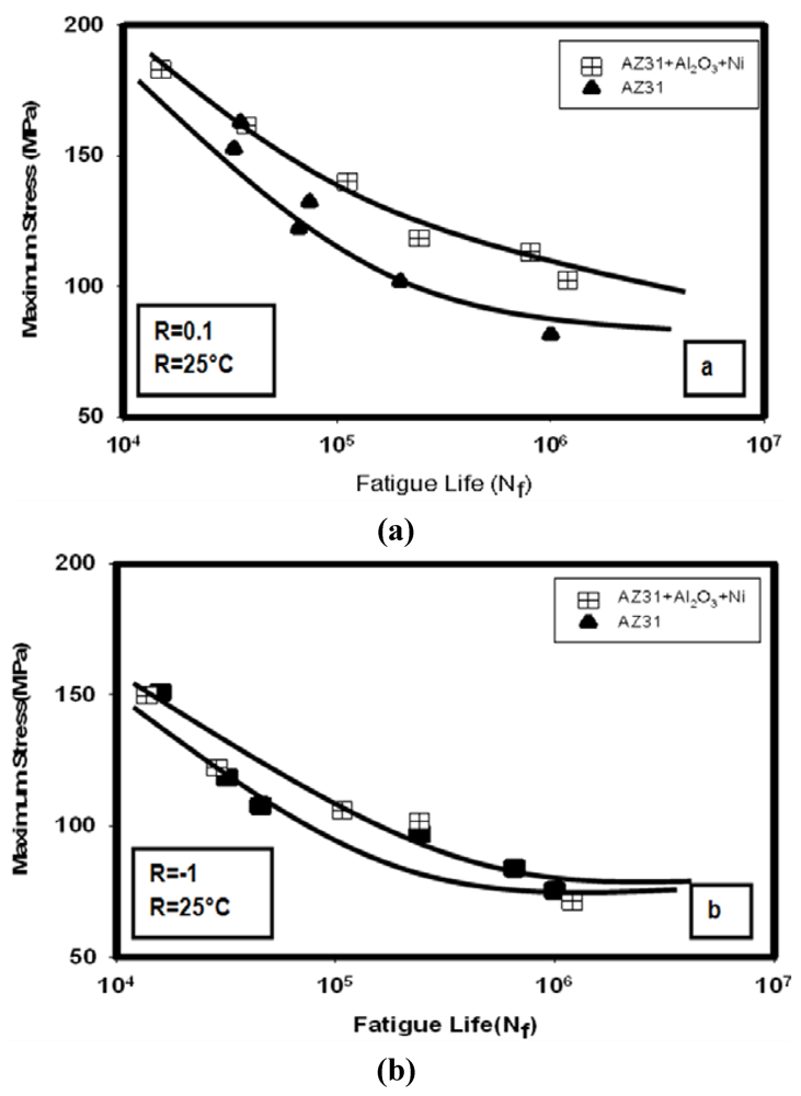
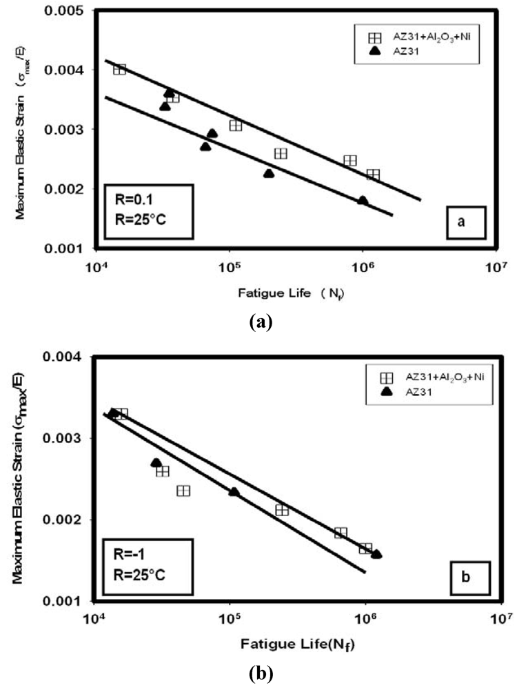
4.3. Stress Amplitude Controlled High Cycle Fatigue Response</title>
        <p>The results of the stress-controlled high cycle fatigue tests are shown in <xref ref-type="fig" rid="metals-02-00143-f003">Figure 3</xref>–<xref ref-type="fig" rid="metals-02-00143-f006">Figure 6</xref>. The maximum strains generated during fatigue testing are predominantly elastic in nature while the maximum applied stresses are well below the tensile yield strength of both the composite material and the monolithic counterpart. The plastic deformation is confined to occur at the microscopic heterogeneities in the microstructure and is conducive to the initiation of a crack, which is essentially microscopic in nature. Continued growth of the fine microscopic cracks through the microstructure of this magnesium alloy-based composite during repeated cyclic stressing results in their eventual coalescence to form a visible macroscopic crack. Concurrent growth of both the fine microscopic and macroscopic cracks through the microstructure of the composite results in failure of the test specimen. During stress amplitude-controlled cyclic loading the property changes, if any, are expected to occur both at the crack tip and the region immediately in front of an advancing crack tip, while the material in the far field remains essentially unaffected. Further, under conditions of stress-controlled fatigue, the most part of the fatigue life is spent in the initiation of an observable crack that is macroscopic in size. The stress-amplitude-controlled fatigue test provides a useful measure of the endurance limit of the candidate composite material at the chosen load ratio (R = σ<sub>minimum</sub>/σ<sub>maximum</sub>).</p>
        
        
        <sec>
          <title>4.3.1. Load Ratio [R] = 0.1</title>
          <p>The stress amplitude controlled tension-tension type tests were carried out over a maximum stress ranging from 102 MPa to 183 MPa and shown in <xref ref-type="fig" rid="metals-02-00143-f003">Figure 3</xref> to <xref ref-type="fig" rid="metals-02-00143-f006">Figure 6</xref>. The variation of maximum stress (σ<sub>maximum</sub>) with cyclic fatigue life (N<sub>f</sub>) is shown in <xref ref-type="fig" rid="metals-02-00143-f003">Figure 3</xref>a. The endurance limit of the dual-particle reinforced magnesium alloy composite, taken at 10<sup>6</sup> cycles, was 100 MPa while the endurance limit of the unreinforced alloy (AZ31), taken at 10<sup>6 </sup>cycles, was only 80 MPa. Thus, there occurs a twenty-five percent improvement in the cyclic endurance limit of the dual particle-reinforced magnesium alloy composite over the contending monolithic alloy (AZ31). Also observed was that at all values of maximum stress the fatigue life of the dual particle reinforced magnesium alloy composite was superior or better than the unreinforced magnesium alloy. At equivalent values of maximum stress the improvement in fatigue life was as high as 100 pct. In fact, the difference in cyclic fatigue life between the two materials increased with a decrease in maximum stress and resultant enhanced fatigue life. To have a better understanding of the intrinsic influence of ductility of this material on high cycle fatigue response the test data shown in <xref ref-type="fig" rid="metals-02-00143-f003">Figure 3</xref>a is replotted in terms of maximum elastic strain (defined as σ<sub>maximum</sub>/E). This is shown in <xref ref-type="fig" rid="metals-02-00143-f004">Figure 4</xref>a and clearly reveals the monolithic alloy (AZ31) to be inferior to the dual particle-reinforced magnesium alloy composite (AZ31/1.5 Al<sub>2</sub>O<sub>3</sub>/1.5 Ni) at all values of the ratio of maximum elastic strain. A viable reason for the observed reduction in cyclic fatigue life, or low fatigue life, at the higher values of maximum stress is primarily because high stress facilitates the early initiation of one or more fine microscopic cracks. During continued cyclic deformation a gradual growth of the fine microscopic cracks through the microstructure of the composite culminates in their eventual coalescence to form a macroscopic crack or the microscopic crack merely grows in size to become a macroscopic crack. Concurrent growth of both the fine microscopic and macroscopic cracks through the microstructure of both the unreinforced and reinforced magnesium alloy composite gradually reduces the stress carrying capability of the material culminating in its failure.</p>
           <p>From a design engineering perspective the variation of maximum stress to yield stress (σ<sub>maximum</sub>/σ<sub>yield</sub>) as a function of cyclic fatigue life (N<sub>f</sub>) is shown in <xref ref-type="fig" rid="metals-02-00143-f005">Figure 5</xref>a. At all values of this ratio the dual particle-reinforced magnesium alloy composite revealed improved fatigue life when compared to the unreinforced monolithic counterpart. At high values of this ratio (σ<sub>maximum</sub>/σ<sub>yield</sub>), the improvement in cyclic fatigue life over the monolithic counterpart is observable and between 50 to 100 pct and gradually increases with a decrease in the ratio of σ<sub>maximum</sub>/σ<sub>yield</sub>.</p>
           <fig id="metals-02-00143-f003" position="anchor">
          <label>Figure 3</label>
          <caption>
            <p>Comparison of the variation of maximum stress with fatigue life (N<sub>f</sub>) of the dual particle reinforced magnesium alloy (AZ31 + Al<sub>2</sub>O<sub>3</sub> + Ni) with the unreinforced matrix alloy (AZ31) cyclically deformed at room temperature (T = 25 °C) at: (<bold>a</bold>) Load ratio of 0.1 and (<bold>b</bold>) Load ratio of −1.0.</p>
          </caption>
          <graphic xmlns:xlink="http://www.w3.org/1999/xlink" xlink:href="metals-02-00143-g003.tif"/>
        </fig>
          <fig id="metals-02-00143-f004" position="anchor">
            <label>Figure 4</label>
            <caption>
              <p>Comparison of the variation of maximum elastic strain [maximum stress to modulus of elasticity (E)] with fatigue life (N<sub>f</sub>) of the dual particle reinforced magnesium alloy (AZ31 + Al<sub>2</sub>O<sub>3 </sub>+ Ni) with the unreinforced matrix alloy (AZ31) cyclically deformed at room temperature (T = 25 °C) at: (<bold>a</bold>) Load ratio of 0.1; (<bold>b</bold>) Load ratio of −1.0.</p>
            </caption>
            <graphic xmlns:xlink="http://www.w3.org/1999/xlink" xlink:href="metals-02-00143-g004.tif"/>
          </fig>
         
          
          <fig id="metals-02-00143-f005" position="anchor">
            <label>Figure 5</label>
            <caption>
              <p>Comparison of the variation of ratio of maximum stress to yield stress with fatigue life (N<sub>f</sub>) of the dual particle reinforced magnesium alloy (AZ31 + Al<sub>2</sub>O<sub>3 </sub>+ Ni) with the unreinforced matrix alloy (AZ31) cyclically deformed at room temperature (T = 25 °C) at: (<bold>a</bold>) Load ratio of 0.1; (<bold>b</bold>) Load ratio of −1.0.</p>
            </caption>
            <graphic xmlns:xlink="http://www.w3.org/1999/xlink" xlink:href="metals-02-00143-g005.tif"/>
          </fig>
        </sec>
        <sec>
          <title>
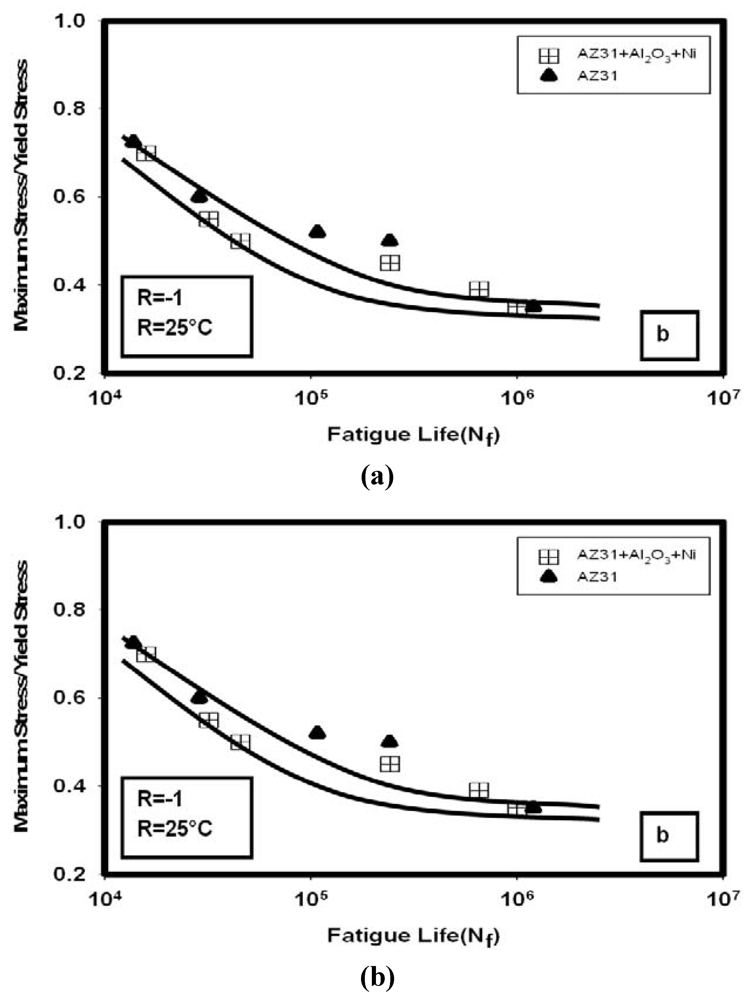
4.3.2. Load Ratio [R] = −1.0</title>
          <p>The results obtained from high cycle fatigue tests, under conditions of fully reversed loading, are shown in <xref ref-type="fig" rid="metals-02-00143-f003">Figure 3</xref>b to <xref ref-type="fig" rid="metals-02-00143-f005">Figure 5</xref>b. The tests were carried out over a maximum stress ranging from 75 MPa to 151 MPa. The variation of maximum stress (σ<sub>maximum</sub>) with cyclic fatigue life (N<sub>f</sub>) is shown in <xref ref-type="fig" rid="metals-02-00143-f003">Figure 3</xref>b. The monolithic alloy has an endurance limit of 70 MPa, taken at 10<sup>6</sup> cycles, while the magnesium alloy composite (AZ31/1.5 Al<sub>2</sub>O<sub>3</sub>/1.5 Ni) has an endurance limit of 95 MPa, taken at 10<sup>6 </sup>cycles. The net improvement in the endurance stress limit of this dual particle-reinforced magnesium alloy composite when compared one-on-one with the unreinforced monolithic counterpart (AZ31) is as high as 35 pct. Further, at equivalent values of maximum stress, the dual particle-reinforced magnesium alloy revealed only a marginal difference in cyclic fatigue life when compared one-on-one with the unreinforced monolithic counterpart (AZ31) (<xref ref-type="fig" rid="metals-02-00143-f003">Figure 3</xref>b).</p>
          <fig id="metals-02-00143-f006" position="anchor">
          <label>Figure 6</label>
          <caption>
            <p>Comparison of the influence of load ratio (0.1 <italic>versus</italic> −1.0) on variation of maximum stress with fatigue life (N<sub>f</sub>) for test specimens cyclically deformed at room temperature (T = 25 °C) for: (<bold>a</bold>) Magnesium alloy AZ31; (<bold>b</bold>) Magnesium composite (AZ31/Al<sub>2</sub>O<sub>3</sub>/Ni).</p>
          </caption>
          <graphic xmlns:xlink="http://www.w3.org/1999/xlink" xlink:href="metals-02-00143-g006.tif"/>
        </fig>
          <p>The variation of elastic strain (σ<sub>maximum</sub>/E) with cyclic fatigue life (N<sub>f</sub>) is shown in <xref ref-type="fig" rid="metals-02-00143-f004">Figure 4</xref>b. From this figure it is clearly seen that the difference in behavior between the monolithic alloy (AZ31) and the composite over the entire range of maximum elastic strain is at best minimal to negligible. A slight difference is noticeable at all of the values of the maximum elastic strain. From a design engineering perspective the variation of the ratio of maximum stress to yield stress (σ<sub>maximum</sub>/σ<sub>yield</sub>) as a function of fatigue life (N<sub>f</sub>) is shown in <xref ref-type="fig" rid="metals-02-00143-f005">Figure 5</xref>b. At high values of this ratio the difference in cyclic fatigue life between the two materials is minimal and can be ascribed to the short fatigue lives of the two materials. The differences in fatigue behavior gradually decrease at the lower values of the ratio of σ<sub>maximum</sub>/σ<sub>yield</sub> and result in enhanced fatigue life. It is only at intermediate values of this ratio of σ<sub>maximum</sub>/σ<sub>yield</sub> that the difference in fatigue behavior between the monolithic alloy and the composite is evident and noticeable.</p>
        </sec>
        <sec>
          <title>
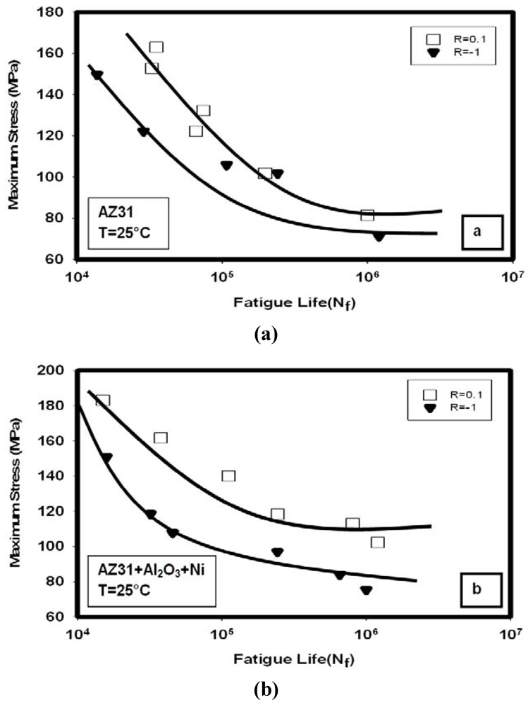
4.3.3. Comparison of Cyclic Fatigue Behavior at load ratios [R] of 0.1 and −1.0</title>
          <p>A comparison of the fatigue behavior of each candidate material, <italic>i.e.</italic>, unreinforced AZ31 and dual particle-reinforced composite (AZ31/Al<sub>2</sub>O<sub>3</sub>/Ni), at the two load ratios is shown in <xref ref-type="fig" rid="metals-02-00143-f006">Figure 6</xref>. For the unreinforced monolithic alloy a decrease in load ratio from 0.1 to −1.0 resulted in a decrease in cyclic fatigue life. The difference in fatigue life between the two load ratios gradually decreased with a decrease in maximum stress and resultant enhanced fatigue life (N<sub>f</sub>) (<xref ref-type="fig" rid="metals-02-00143-f006">Figure 6</xref>a). For the AZ31/Al<sub>2</sub>O<sub>3</sub>/Ni composite a decrease in load ratio from 0.1 to −1.0 also resulted in degradation in cyclic fatigue life. At equivalent values of maximum stress from very low stress to very high stress, the degradation in fatigue life was as high as 100–150 pct. The differences in fatigue life between the two materials became evident at the higher values of maximum stress (<xref ref-type="fig" rid="metals-02-00143-f006">Figure 6</xref>b).</p>
        </sec>
      </sec>
      <sec>
        <title>
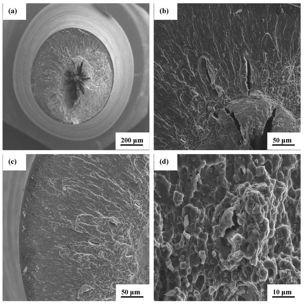
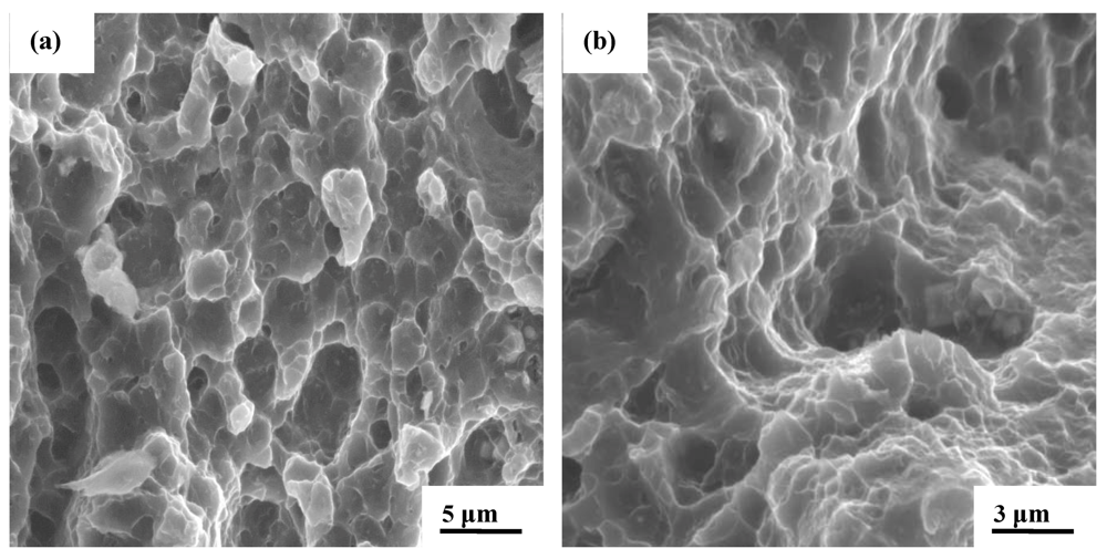
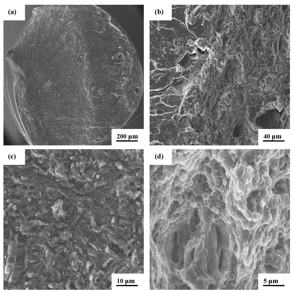
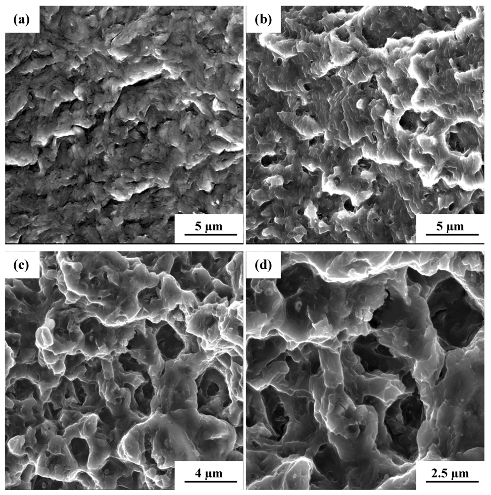
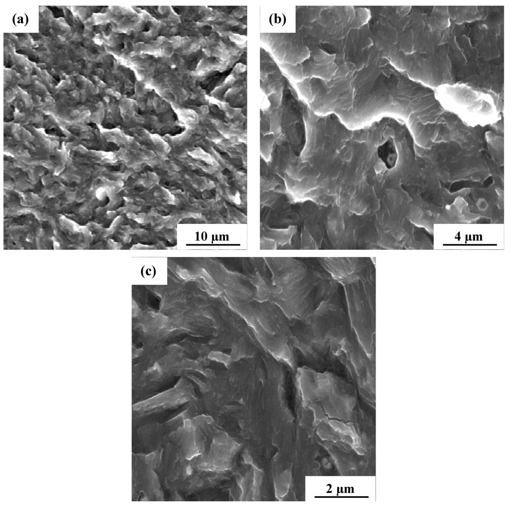
4.4. Cyclic Fatigue Fracture</title>
        <p>The fracture surfaces of the cyclically deformed and failed test specimens were carefully and comprehensively examined in a scanning electron microscope (Model: FEI Quanta 200) to establish the macroscopic fracture mode and to concurrently characterize the intrinsic microscopic features decorating the fracture surface and thereby help establish the mechanisms governing fracture. Only representative fracture features of the nickel-particle reinforced magnesium alloy composite (AZ31/1.5 vol.% Al<sub>2</sub>O<sub>3</sub>/Ni) and the unreinforced magnesium alloy (AZ31) at the two load ratios of 0.1 and −1.0 taken at high value of maximum stress and resultant short fatigue life and low value of maximum stress and resultant enhanced fatigue life are shown in <xref ref-type="fig" rid="metals-02-00143-f007">Figure 7</xref>–<xref ref-type="fig" rid="metals-02-00143-f012">Figure 12</xref>.</p>
        
        <sec>
          <title>4.4.1. Load Ratio [R] = 0.10</title>
        
        <sec>
          <title>(A) The dual-particle reinforced composite: AZ31/1.5 vol.% Al<sub>2</sub>O<sub>3</sub>/Ni</title>
          <p>The test specimen of the dual particle-reinforced magnesium alloy composite that was deformed at a maximum stress of 183.14 MPa and a resultant fatigue life of 15,009 cycles, the key features are shown in <xref ref-type="fig" rid="metals-02-00143-f007">Figure 7</xref>. A macroscopic fracture as shown in <xref ref-type="fig" rid="metals-02-00143-f007">Figure 7</xref>a is the cone region of a typical cup and cone fracture. At this low magnification both the smooth and rough regions representative of fatigue and overload low magnification. Also, the smooth region is representative of early microscopic crack growth while the rough region of the fracture surface is representative of unstable crack growth and overload. Careful examination at higher allowable magnifications of <xref ref-type="fig" rid="metals-02-00143-f007">Figure 7</xref>a revealed the transgranular fracture regions to be essentially flat, smooth and containing isolated macroscopic cracks (<xref ref-type="fig" rid="metals-02-00143-f007">Figure 7</xref>b). The transition region between fatigue and overload was narrow yet visibly distinct (<xref ref-type="fig" rid="metals-02-00143-f007">Figure 7</xref>c). This region contained a noticeable volume fraction of distinctly different fine microscopic features spanning microscopic cracks, shallow dimples and few fine microscopic voids (<xref ref-type="fig" rid="metals-02-00143-f007">Figure 7</xref>d). These fine microscopic features are indicative of the occurrence of ductile and brittle failure mechanisms at the ‘local’ level. Moving onto the region of overload reveals a healthy population of well-defined dimples interdispersed with fine microscopic voids (<xref ref-type="fig" rid="metals-02-00143-f008">Figure 8</xref>a). The very center of the region of overload was covered with a sizeable number of shallow dimples (<xref ref-type="fig" rid="metals-02-00143-f008">Figure 8</xref>b) representative of the occurrence of “locally” operating ductile failure mechanisms.</p>
          <fig id="metals-02-00143-f007" position="anchor">
          <label>Figure 7</label>
          <caption>
            <p>Scanning electron micrographs of the high cycle fatigue fracture surface of AZ31 + Al<sub>2</sub>O<sub>3</sub> containing 1.5 wt pct nickel deformed at maximum cyclic stress of 183.14 MPa at load ratio of 0.1, fatigue life of 15,009 cycles, showing the following: (<bold>a</bold>) Overall morphology of failure; (<bold>b</bold>) High magnification observation of (a) showing the transgranular fracture surface with isolated macroscopic cracks; (<bold>c</bold>) The transition region between fatigue and overload showing the distinctly different features on the fracture surface and (<bold>d</bold>) High magnification observation of the transition region showing isolated pockets of shallow dimples.</p>
          </caption>
          <graphic xmlns:xlink="http://www.w3.org/1999/xlink" xlink:href="metals-02-00143-g007.tif"/>
        </fig>
        <fig id="metals-02-00143-f008" position="anchor">
            <label>Figure 8</label>
            <caption>
              <p>Scanning electron micrographs of the high cycle fatigue fracture surface of AZ31 + Al<sub>2</sub>O<sub>3</sub> containing 1.5 wt pct nickel deformed at maximum cyclic stress of 183.14 MPa at load ratio of 0.1, fatigue life of 15,009 cycles, showing the following: (<bold>a</bold>) The region of overload showing a population of dimples interdispersed with fine microscopic voids and (<bold>b</bold>) At the “heart” of the overload region reveals a noticeable quantity of shallow dimples reminiscent of locally operating ductile failure mechanisms.</p>
            </caption>
            <graphic xmlns:xlink="http://www.w3.org/1999/xlink" xlink:href="metals-02-00143-g008.tif"/>
          </fig>
          <p>At a maximum stress of 113.11 MPa and a resultant enhanced cyclic fatigue life of 805,217 cycles, the key features observed for this test specimen are shown in <xref ref-type="fig" rid="metals-02-00143-f009">Figure 9</xref>. Overall morphology of failure was initially flat and normal to the far-field stress axis and at a slight inclination in the domain of overload, <italic>i.e.</italic>, immediately prior to failure (<xref ref-type="fig" rid="metals-02-00143-f009">Figure 9</xref>a). High magnification observation of <xref ref-type="fig" rid="metals-02-00143-f009">Figure 9</xref>a revealed the transition region between fatigue and overload to be flat, smooth and containing randomly dispersed fine microscopic cracks (<xref ref-type="fig" rid="metals-02-00143-f009">Figure 9</xref>b). Approaching the region of early microscopic crack growth pockets of shallow randomly dispersed striations reminiscent of the occurrence of ‘localized’ microplastic deformation were revealed (<xref ref-type="fig" rid="metals-02-00143-f009">Figure 9</xref>c). The region of overload (<xref ref-type="fig" rid="metals-02-00143-f009">Figure 9</xref>d) revealed an observable population of dimples interdispersed with fine microscopic voids and fine microscopic cracks. These fine microscopic features are representative of the occurrence of both brittle and ductile failure mechanisms at the microscopic level.</p>
          <fig id="metals-02-00143-f009" position="anchor">
            <label>Figure 9</label>
            <caption>
              <p>Scanning electron micrographs of the high cycle fatigue fracture surface of AZ31 + Al<sub>2</sub>O<sub>3</sub> containing 1.5 wt pct nickel deformed at maximum cyclic stress of 113.11 MPa at load ratio of 0.1, fatigue life of 805,217 cycles, showing the following: (<bold>a</bold>) Overall morphology of failure; (<bold>b</bold>) High magnification observation of (a) at the transition region between fatigue and overload; (<bold>c</bold>) Profile of fracture surface and key features in the region of early microscopic crack growth; (<bold>d</bold>) The region of overload revealing an observable population of dimples interdispersed with fine microscopic voids and microscopic cracks.</p>
            </caption>
            <graphic xmlns:xlink="http://www.w3.org/1999/xlink" xlink:href="metals-02-00143-g009.tif"/>
          </fig>
        </sec>
        <sec>
          <title>(B) The Monolithic Alloy AZ31</title>
          <p>The key features observed for the monolithic alloy cyclically deformed at a maximum stress of 152.72 MPa resulting in a fatigue life of 32,940 cycles, as shown in <xref ref-type="fig" rid="metals-02-00143-f010">Figure 10</xref>. The region of early microscopic crack growth was predominantly transgranular. The key features observed in the transgranular fracture regions is shown in <xref ref-type="fig" rid="metals-02-00143-f010">Figure 10</xref>a. High magnification observation of this region and approaching the region of stable crack growth revealed a random distribution of fine microscopic voids intermingled with shallow dimples, features which are indicative of the occurrence of locally operating ductile failure mechanisms (<xref ref-type="fig" rid="metals-02-00143-f010">Figure 10</xref>c). Approaching the region of overload, the fracture surface revealed shallow dimples of varying size and shape when observed at higher magnifications. Intermingled between the sizeable population of dimples were fine microscopic voids (<xref ref-type="fig" rid="metals-02-00143-f010">Figure 10</xref>b).</p>
          <fig id="metals-02-00143-f010" position="anchor">
            <label>Figure 10</label>
            <caption>
              <p>Scanning electron micrographs of the high cycle fatigue fracture surface of AZ31 deformed at maximum cyclic stress of 152.72 MPa at load ratio of 0.1, fatigue life of 32,940 cycles, showing the following: (<bold>a</bold>) Transgranular fracture in the region of early crack growth; (<bold>b</bold>) Shallow dimples of varying size and shape covering the region of overload fracture surface and (<bold>c</bold>) High magnification observation of the region of crack initiation and early microscopic growth showing a random distribution of fine microscopic voids. </p>
            </caption>
            <graphic xmlns:xlink="http://www.w3.org/1999/xlink" xlink:href="metals-02-00143-g010.tif"/>
          </fig>
          <p>The key and intrinsic features observed on the surface of the test specimen that was deformed at a maximum stress of 102 MPa with a resultant fatigue life of 197,813 cycles are shown in <xref ref-type="fig" rid="metals-02-00143-f011">Figure 11</xref>. The region of crack initiation and early microscopic crack growth when observed at low magnifications was rough and covered with a sizeable population of dimples intermingled with both fine microscopic voids and fine microscopic cracks. These fine features are representative of the occurrence of both ductile and brittle failure mechanisms at the fine microscopic level (<xref ref-type="fig" rid="metals-02-00143-f011">Figure 11</xref>a). High magnification observation in this region revealed pockets of randomly dispersed striations indicative of the occurrence of micro-plastic deformation at the ‘local’ level (<xref ref-type="fig" rid="metals-02-00143-f011">Figure 11</xref>b). Gradually traversing through the fracture surface and approaching the region of stable crack growth revealed pockets of well-defined striations, randomly oriented and distinctly evidently covering the fracture surface (<xref ref-type="fig" rid="metals-02-00143-f011">Figure 11</xref>c). In the region immediately prior to the onset of unstable crack growth evident cracking along the grain boundaries was found in addition to shallow pockets of well-defined striations (<xref ref-type="fig" rid="metals-02-00143-f011">Figure 11</xref>d).</p>
          <fig id="metals-02-00143-f011" position="anchor">
            <label>Figure 11</label>
            <caption>
              <p>Scanning electron micrographs of the high cycle fatigue fracture surface of AZ31 deformed at maximum cyclic stress of 102 MPa at load ratio of 0.1, fatigue life of 197,813 cycles, showing the following: (<bold>a</bold>) The region of crack initiation and early microscopic crack growth; (<bold>b</bold>) A random dispersion of fine striations in the region of early microscopic crack growth; (<bold>c</bold>) High magnification observation if (a) showing the nature and distribution of striations in the region of early crack growth; (<bold>d</bold>) Cracking along the grain boundaries observed immediately prior to unstable crack growth. </p>
            </caption>
            <graphic xmlns:xlink="http://www.w3.org/1999/xlink" xlink:href="metals-02-00143-g011.tif"/>
          </fig>
        </sec>
        </sec>
        <sec>
          <title>
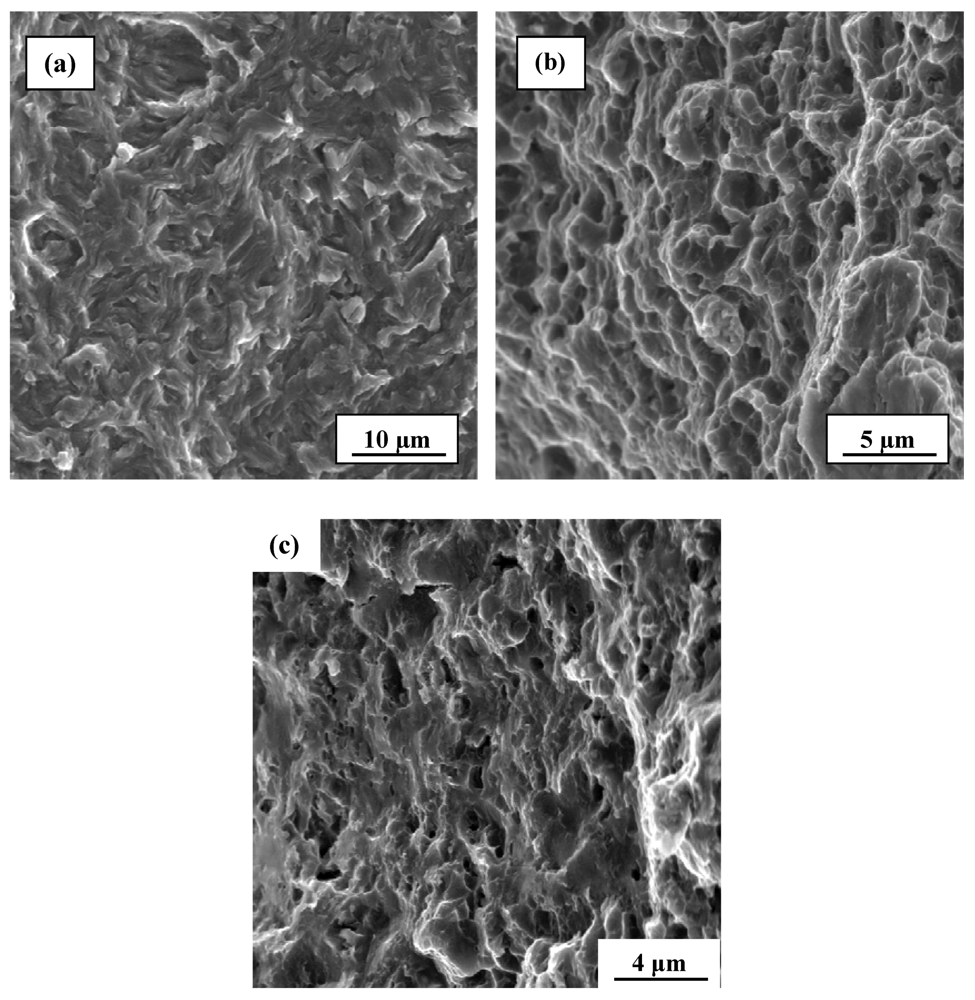
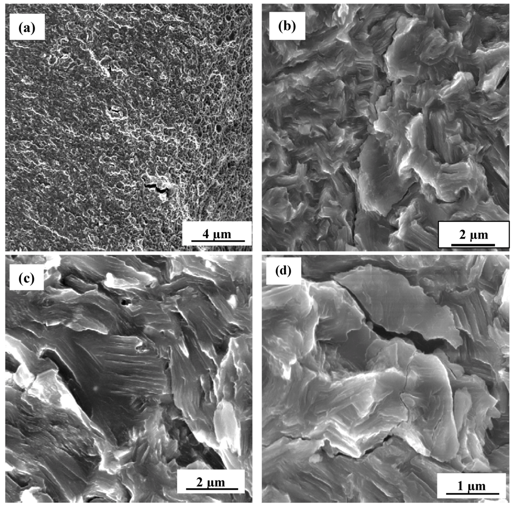
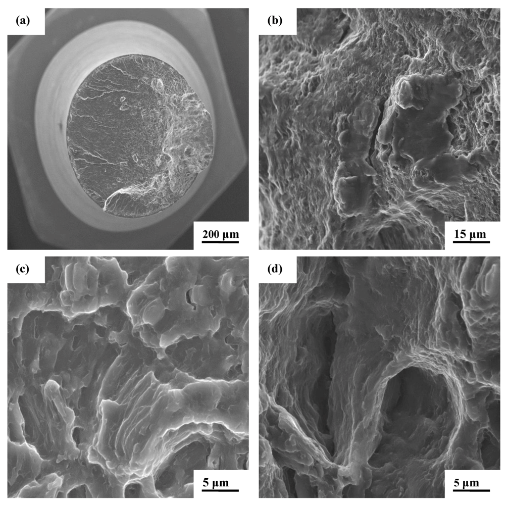
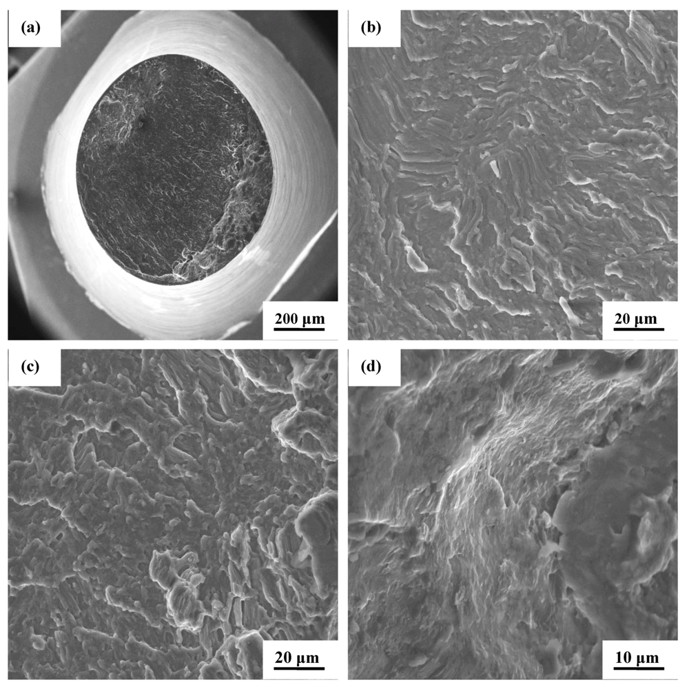
4.4.2. Load Ratio [R] = −1.0</title>
        
        <sec>
          <title>(A) The dual-particle reinforced composite: AZ31/1.5 vol.% Al<sub>2</sub>O<sub>3</sub>/Ni</title>
          <p>The key features observed for the composite test specimen that was cyclically deformed at a maximum stress of 150.82 MPa resulting in a fatigue life of 15,920 cycles is shown in <xref ref-type="fig" rid="metals-02-00143-f012">Figure 12</xref>. The overall morphology of failure was macroscopically smooth and predominantly normal to the far-field stress axis (<xref ref-type="fig" rid="metals-02-00143-f012">Figure 12</xref>a). Gradual high magnification observation of <xref ref-type="fig" rid="metals-02-00143-f012">Figure 12</xref>a revealed the key intrinsic features in the region spanning crack initiation and early microscopic crack growth and is shown in <xref ref-type="fig" rid="metals-02-00143-f012">Figure 12</xref>b. The region of stable crack growth revealed pockets of shallow and well-defined striations (<xref ref-type="fig" rid="metals-02-00143-f012">Figure 12</xref>c). The striations are indicative of the occurrence of microplastic deformations at the “local” level. The region of overload revealed macroscopic voids, few to several fine microscopic cracks, and an observable population of shallow dimples (<xref ref-type="fig" rid="metals-02-00143-f012">Figure 12</xref>d). These fine microscopic features are clearly indicative of the occurrence of both ductile and brittle failure mechanisms at the fine microscopic level.</p>
          <fig id="metals-02-00143-f012" position="anchor">
          <label>Figure 12</label>
          <caption>
            <p>Scanning electron micrographs of the high cycle fatigue fracture surface of AZ31 + Al<sub>2</sub>O<sub>3</sub> containing 1.5 wt pct nickel deformed at maximum cyclic stress of 150.82 MPa at load ratio of −1, fatigue life of 15,920 cycles, showing the following: (<bold>a</bold>) Overall morphology of fracture surface predominantly normal to the far field stress axis; (<bold>b</bold>) High magnification observation of (a) showing key intrinsic features in the region of early crack initiation and early microscopic crack growth; (<bold>c</bold>) Pockets of shallow, yet well defined striations in the region of stable crack growth and (<bold>d</bold>) The overload fracture surface revealing macroscopic void and crack interdispersed with shallow dimples of varying size.</p>
          </caption>
          <graphic xmlns:xlink="http://www.w3.org/1999/xlink" xlink:href="metals-02-00143-g012.tif"/>
        </fig>
          <p>The key features observed for the test specimen of this dual particle reinforced magnesium alloy composite that was cyclically deformed at a maximum stress of 84.03 MPa and had a resultant fatigue life of 655,970 cycles are shown in <xref ref-type="fig" rid="metals-02-00143-f013">Figure 13</xref>. The overall morphology of failure was flat and essentially normal to the far-field stress axis and revealed both smooth and rough regions reminiscent of fatigue deformation and overload (<xref ref-type="fig" rid="metals-02-00143-f013">Figure 13</xref>a). At gradually higher magnification, observation of the fatigue fracture surface in the region of early microscopic crack growth revealed well-defined pockets of randomly dispersed striations (<xref ref-type="fig" rid="metals-02-00143-f013">Figure 13</xref>b). In the region of unstable crack growth immediately prior to overload revealed shallow striations clearly indicative of stable crack growth through the composite microstructure (<xref ref-type="fig" rid="metals-02-00143-f013">Figure 13</xref>c). At the transition region between fatigue and overload the fatigue fracture surface was covered with fine microscopic voids and shallow dimples (<xref ref-type="fig" rid="metals-02-00143-f013">Figure 13</xref>d). These intrinsic features covering the fracture surface are representative of the occurrence of both ductile and brittle failure mechanisms at the fine “microscopic” level.</p>
          
        </sec>
        <sec>
          <title>(B) The Monolithic Alloy AZ31</title>
          <p>The features of the monolithic unreinforced counterpart that was cyclically deformed at a maximum stress of 149.67 MPa with a fatigue life of 13,802 cycles, are shown in <xref ref-type="fig" rid="metals-02-00143-f014">Figure 14</xref>. High magnification observation of the overall fracture surface at permissible magnifications of the SEM revealed a combination of both macroscopic and fine microscopic cracks were evident (<xref ref-type="fig" rid="metals-02-00143-f014">Figure 14</xref>a). In the region of stable crack growth evident fine and shallow striation-like features (<xref ref-type="fig" rid="metals-02-00143-f014">Figure 14</xref>b). The presence of striations is indicative of the occurrence of micro-plastic deformation. The region of overload was covered with a sizeable population of voids of varying sizes and shallow dimples, indicative of limited void growth prior to catastrophic failure (<xref ref-type="fig" rid="metals-02-00143-f014">Figure 14</xref>c). The voids and dimples, though shallow in nature, suggest the occurrence of ductile failure mechanisms at the fine microscopic level. High magnification observation of the overload region revealed the voids to be both irregular in size and shape (<xref ref-type="fig" rid="metals-02-00143-f014">Figure 14</xref>d).</p>
          <fig id="metals-02-00143-f013" position="anchor">
            <label>Figure 13</label>
            <caption>
              <p>Scanning electron micrographs of the high cycle fatigue fracture surface of AZ31 + Al<sub>2</sub>O<sub>3</sub> containing 1.5 wt pct nickel deformed at maximum cyclic stress of 84.03 MPa at load ratio of −1, fatigue life of 655,970 cycles, showing the following: (<bold>a</bold>) Overall morphology of the fracture surface predominantly normal to the far field stress axis; (<bold>b</bold>) High magnification observation of (a) in the region of early microscopic crack growth showing pockets of randomly dispersed striations; (<bold>c</bold>) The key features on the fracture surface with shallow striations in the region immediately prior to overload and (<bold>d</bold>) The transition region between the smooth fatigue region and overload laden with fine microscopic voids and shallow dimples.</p>
            </caption>
            <graphic xmlns:xlink="http://www.w3.org/1999/xlink" xlink:href="metals-02-00143-g013.tif"/>
          </fig>
          <fig id="metals-02-00143-f014" position="anchor">
            <label>Figure 14</label>
            <caption>
              <p>Scanning electron micrographs of the high cycle fatigue fracture surface of AZ31 cyclically deformed at maximum stress of 149.67 MPa and load ratio of −1.0 and fatigue life of 13,802 cycles, showing: (<bold>a</bold>) High magnification observation of (<bold>b</bold>) showing an array of macroscopic cracks and fine microscopic cracks; (<bold>b</bold>) Fine and shallow striation-like features in the region of stable crack growth; (<bold>c</bold>) The overload fracture surface showing voids and shallow dimples reminiscent of locally ductile failure and (<bold>d</bold>) High magnification of (b) showing the irregular size and shape of the voids.</p>
            </caption>
            <graphic xmlns:xlink="http://www.w3.org/1999/xlink" xlink:href="metals-02-00143-g014.tif"/>
          </fig>
          <p>The test sample of the monolithic alloy that was cyclically deformed at a lower maximum stress of 101.82 MPa and the resultant enhanced fatigue life of 240,921 cycles are the key features that are shown in <xref ref-type="fig" rid="metals-02-00143-f015">Figure 15</xref>. The region of early microscopic crack growth was flat and inlaid with randomly distributed microscopic cracks (<xref ref-type="fig" rid="metals-02-00143-f015">Figure 15</xref>a). Gradually traversing the fracture surface and approaching the region of stable crack growth provided evidence of the presence of fine microscopic voids and microscopic cracks, features indicative of the occurrence of both ductile and brittle mechanisms at the fine microscopic level (<xref ref-type="fig" rid="metals-02-00143-f015">Figure 15</xref>b). High magnification observation in the region of stable crack growth immediately prior to the onset of unstable crack growth revealed fine microscopic cracks intermingled with shallow striations (<xref ref-type="fig" rid="metals-02-00143-f015">Figure 15</xref>c). These features are also indicative of the occurrence of both brittle and ductile failure mechanisms at the local level.</p>
          <fig id="metals-02-00143-f015" position="anchor">
            <label>Figure 15</label>
            <caption>
              <p>Scanning electron micrographs of the high cycle fatigue fracture surface of magnesium alloy AZ31 cyclically deformed at maximum stress of 101.82 MPa, at load ratio of −1. And resultant fatigue life of 240,921 cycles, showing: (<bold>a</bold>) Intrinsic features in the region of early microscopic crack growth; (<bold>b</bold>) Microscopic voids and microscopic cracks observed in the region of stable crack growth and (<bold>c</bold>) High magnification observation of the region of stable crack growth prior to the onset of unstable crack growth revealing fine microscopic cracks and shallow nature of striations.</p>
            </caption>
            <graphic xmlns:xlink="http://www.w3.org/1999/xlink" xlink:href="metals-02-00143-g015.tif"/>
          </fig>
        </sec>
      </sec>
      </sec>
      <sec>
        <title>4.5. Microscopic Mechanisms Governing Cyclic Deformation and Fracture</title>
        <p>The constraints to mechanical deformation induced by the physical presence of hard and essentially elastically deforming nano-sized aluminum oxide (Al<sub>2</sub>O<sub>3</sub>) particle and micron-size nickel particle reinforcements on the soft, ductile and essentially plastically deforming magnesium alloy (AZ31) metal matrix coupled with the resultant development of matrix triaxiality does exert an influence of flow stress on deformation capability of the magnesium alloy [<xref ref-type="bibr" rid="B23-metals-02-00143">23</xref>,<xref ref-type="bibr" rid="B24-metals-02-00143">24</xref>]. Under the influence of cyclic loading the fine microscopic voids appeared to have undergone only limited growth confirming a possible contribution from the nanosize Al<sub>2</sub>O<sub>3</sub> and micron-size nickel particulate reinforcements on the failure of the composite. The locally existing triaxial stresses that exist as a direct consequence of far-field loading favor only a limited growth of the fine microscopic voids in the magnesium alloy metal matrix. The limited growth of the fine microscopic voids, during far-field loading, coupled with a lack of their coalescence with each other and companion macroscopic voids to be the dominant fracture mode for this magnesium alloy composite, clearly indicate that the deformation properties of the magnesium alloy (AZ31) are noticeably altered by the presence of both nano-size aluminum oxide and micron-size nickel particle reinforcements.</p>
        <p>In fact, ductile crack initiation in this metal matrix composite results from void growth and eventual coalescence. This is made possible under the combined influence of “local” plastic strain and hydrostatic tensile stress. When the plastic strains exist in the presence of hydrostatic tension stress, the fine microscopic voids that nucleate around the reinforcing particles begin to grow. A gradual increase in size of the growing void intensifies the strain between neighboring voids until void-void interactions result in their coalescence culminating in the formation and presence of a macroscopic crack. Overall, the process of void growth and eventual coalescence leading to ductile crack initiation at the microscopic level are affected by void distribution, anisotropy spacing of the reinforcing particles, nature of void initiation, evolution of void shapes, void-to-void interactions and the nucleation and growth of secondary voids that facilitate coalescence. In this magnesium alloy composite the halves of the limited grown microscopic voids are the shallow dimples visible on the fatigue fracture surface [<xref ref-type="bibr" rid="B25-metals-02-00143">25</xref>,<xref ref-type="bibr" rid="B26-metals-02-00143">26</xref>,<xref ref-type="bibr" rid="B27-metals-02-00143">27</xref>,<xref ref-type="bibr" rid="B28-metals-02-00143">28</xref>]. Failure of the reinforcing aluminum oxide (Al<sub>2</sub>O<sub>3</sub>) particulates either through fracture or by decohesion at their interfaces with the magnesium alloy metal matrix was difficult to observe at the allowable magnifications of the SEM due to the small size (nanometer) of the reinforcing particulates. However, the constraints to mechanical deformation, at the fine microscopic level, during cyclic loading coupled with considering the influence of particle reinforcement on strain hardening of this magnesium alloy metal matrix are factors responsible for the improved ductility and marginally improved cyclic fatigue resistance (quantified by fatigue life) of the composite over the unreinforced counterpart. In regions and/or locations of clustering or agglomeration of the Al<sub>2</sub>O<sub>3</sub> nanoparticle reinforcements, the short inter-particle distance is conducive to the linkage between the neighboring voids and resultant microscopic crack.</p>
        <p>For test specimens of both the magnesium alloy composite and the monolithic alloy that were cyclically deformed under fully-reversed loading, the fracture surface did reveal some evidence of brittle fracture at the fine microscopic level. The compression part of the load cycle caused the voids to collapse into oblate or penny-shaped voids, which tended to create sharper stress concentrations than the spherical voids that form in tension-tension cyclic loading and under monotonic tension. On subsequent loading under tension, the highly localized stresses at the circumference of the collapsed voids will tend to favor earlier ruptures of the ligament between voids by promoting alternate failure mechanisms, including microscopic cleavage and microscopic cracking. Thus, the net result of the collapse of the void under fully-reversed loading helps to reduce the critical size of the void. This explains the presence of smaller voids and fine microscopic cracks on the fracture surface of the test specimen that was cyclically deformed under fully reversed loading.</p>
      </sec>
    </sec>
    <sec sec-type="conclusions">
      <title>5. Conclusions</title>
      <p>Based on a study aimed at understanding the specific role and influence of aluminum oxide (Al<sub>2</sub>O<sub>3</sub>) nano-particulates and micron-size nickel particle reinforcements on the stress amplitude controlled high cycle fatigue and final fracture behavior of the magnesium alloy AZ31, the following key observations and findings are presented:</p>
      <list list-type="simple">
        <list-item>
          <p>(1) The unreinforced and reinforced alloy, <italic>i.e.</italic>, composite revealed a duplex microstructure consisting of light colored regions, identified to be the alpha (α) grains, and the dark regions or spots signifying presence of the eutectic phase or the intermetallic particle Mg<sub>17 </sub>Al<sub>12 </sub>the beta (β) phase. The composite microstructure revealed a marginally higher volume fraction of the intermetallic particle dispersed randomly through the microstructure when compared one-on-one with the unreinforced magnesium alloy counterpart. Also present and evident in the composite microstructure were particles of nickel dispersed in a manner to form particle-rich and particle-depleted regions.</p>
        </list-item>
        <list-item>
          <p>(2) The composite (AZ31/Al<sub>2</sub>O<sub>3</sub>/Ni) had a marginally higher yield strength and an observably lower tensile strength than the monolithic alloy (AZ31). The observed decrease in tensile strength is attributed to the mutually interactive influences of mechanisms, which can be found elsewhere in the published literature.</p>
        </list-item>
        <list-item>
          <p>(3) The AZ31/Al<sub>2</sub>O<sub>3</sub>/Ni composite revealed noticeably improved ductility quantified by a reduction in the cross-section area of the test specimen when compared to the monolithic alloy (AZ31).</p>
        </list-item>
        <list-item>
          <p>(4) At a given value of maximum stress, the dual-particle reinforced magnesium alloy composite revealed an improved fatigue life and a better fatigue limit when compared with the monolithic alloy. At equivalent values of maximum stress over the entire range spanning high maximum stress and short fatigue life to low maximum stress and concomitant high fatigue life, the improvement in cyclic fatigue life of the composite over the monolithic counterpart was as high as 50–100 percent.</p>
        </list-item>
        <list-item>
          <p>(5) The monolithic magnesium alloy (AZ31) revealed a noticeably lower endurance limit at the load ratios of 0.1 and −1.0, when compared one-on-one with the composite (AZ31/1.5 vol.% Al<sub>2</sub>O<sub>3</sub>/1.5 vol.% Ni). This indicates and/or suggests the beneficial influence of the dual particle reinforcements on cyclic fatigue resistance of the magnesium alloy by delaying the early initiation of fine microscopic cracks and their concurrent rapid growth through the composite microstructure and eventual coalescence to firm a macroscopic crack. Subsequent growth of both the fine microscopic and macroscopic cracks through the composite microstructure culminates in failure.</p>
        </list-item>
        <list-item>
          <p>(6) On a macroscopic scale, the nature, morphology and volume fraction of the intrinsic features on the fatigue fracture surfaces were found to vary with load ratio, maximum stress and cyclic fatigue life. For the magnesium alloy composite the shallow and not very distinct striations were indicative of the occurrence of micro-plastic deformation at the ‘local’ level and the role played by the compression portion of the load cycle during fully-reversed loading. Under fully reversed loading, the region of overload of this magnesium-alloy composite revealed a lower population of fine microscopic voids intermingled with not very clear and distinct dimples as observed for the monolithic alloy. This suggests the occurrence of limited ductile failure mechanisms at the fine microscopic level for the composite.</p>
        </list-item>
      </list>
    </sec>
  </body>
  <back>
    <ref-list>
      <title>References</title>
      <ref id="B1-metals-02-00143">
        <label>1.</label>
        <citation citation-type="book">
          <source>Magnesium Alloys—Design, Processing and Properties</source>
          <person-group person-group-type="editor">
            <name>
              <surname>Czerwinski</surname>
              <given-names>F.</given-names>
            </name>
            <name>
              <surname>Trojanova</surname>
              <given-names>Z.</given-names>
            </name>
            <name>
              <surname>Szaraz</surname>
              <given-names>Z.</given-names>
            </name>
            <name>
              <surname>Palcek</surname>
              <given-names>P.</given-names>
            </name>
            <name>
              <surname>Chalupova</surname>
              <given-names>M.</given-names>
            </name>
          </person-group>
          <publisher-name>InTech</publisher-name>
          <publisher-loc>Shanghai, China</publisher-loc>
          <year>2011</year>
        </citation>
      </ref>
      <ref id="B2-metals-02-00143">
        <label>2.</label>
        <citation citation-type="journal">
          <person-group person-group-type="author">
            <name>
              <surname>Lloyd</surname>
              <given-names>D.J.</given-names>
            </name>
          </person-group>
          <article-title>Particle reinforced aluminium and magnesium matrix composites</article-title>
          <source>Int. Mater. Rev.</source>
          <year>1994</year>
          <volume>39</volume>
          <fpage>1</fpage>
          <lpage>24</lpage>
          <pub-id pub-id-type="doi">10.1179/095066094790150982</pub-id>
        </citation>
      </ref>
      <ref id="B3-metals-02-00143">
        <label>3.</label>
        <citation citation-type="journal">
          <person-group person-group-type="author">
            <name>
              <surname>Srivatsan</surname>
              <given-names>T.S.</given-names>
            </name>
            <name>
              <surname>Sudarshan</surname>
              <given-names>T.S.</given-names>
            </name>
            <name>
              <surname>Lavernia</surname>
              <given-names>E.J.</given-names>
            </name>
          </person-group>
          <article-title>Processing of discontinuously-reinforced metal matrix composites by rapid solidification</article-title>
          <source>Prog. Mater. Sci.</source>
          <year>1995</year>
          <volume>39</volume>
          <fpage>317</fpage>
          <lpage>409</lpage>
          <pub-id pub-id-type="doi">10.1016/0079-6425(95)00003-8</pub-id>
        </citation>
      </ref>
      <ref id="B4-metals-02-00143">
        <label>4.</label>
        <citation citation-type="journal">
          <person-group person-group-type="author">
            <name>
              <surname>Morisada</surname>
              <given-names>Y.</given-names>
            </name>
            <name>
              <surname>Fujii</surname>
              <given-names>Y.</given-names>
            </name>
            <name>
              <surname>Nagaoka</surname>
              <given-names>H.</given-names>
            </name>
            <name>
              <surname>Fukusumi</surname>
              <given-names>T.</given-names>
            </name>
          </person-group>
          <article-title>Effect of friction stir processing with SiC particles on microstructure and hardness of AZ31</article-title>
          <source>Mater. Sci. Eng. A</source>
          <year>2006</year>
          <volume>433</volume>
          <fpage>50</fpage>
          <lpage>54</lpage>
          <pub-id pub-id-type="doi">10.1016/j.msea.2006.06.089</pub-id>
        </citation>
      </ref>
      <ref id="B5-metals-02-00143">
        <label>5.</label>
        <citation citation-type="journal">
          <person-group person-group-type="author">
            <name>
              <surname>Ho</surname>
              <given-names>K.F.</given-names>
            </name>
            <name>
              <surname>Gupta</surname>
              <given-names>M.</given-names>
            </name>
            <name>
              <surname>Srivatsan</surname>
              <given-names>T.S.</given-names>
            </name>
          </person-group>
          <article-title>The mechanical behavior of magnesium alloy AZ91 reinforced with fine copper particulates</article-title>
          <source>Mater. Sci. Eng. A</source>
          <year>2004</year>
          <volume>369</volume>
          <fpage>302</fpage>
          <lpage>308</lpage>
          <issue>(1-2)</issue>
          <pub-id pub-id-type="doi">10.1016/j.msea.2003.11.011</pub-id>
        </citation>
      </ref>
      <ref id="B6-metals-02-00143">
        <label>6.</label>
        <citation citation-type="book">
          <person-group person-group-type="author">
            <name>
              <surname>Srivatsan</surname>
              <given-names>T.S.</given-names>
            </name>
            <name>
              <surname>Lewandowski</surname>
              <given-names>J.J.</given-names>
            </name>
          </person-group>
          <source>Advanced Structural Materials: Processing, Design Optimization and Applications</source>
          <person-group person-group-type="editor">
            <name>
              <surname>Soboyejo</surname>
              <given-names>W.</given-names>
            </name>
            <name>
              <surname>Srivatsan</surname>
              <given-names>T.S.</given-names>
            </name>
          </person-group>
          <publisher-name>CRC Press</publisher-name>
          <publisher-loc>New York, NY, USA</publisher-loc>
          <year>2009</year>
          <fpage>2699</fpage>
          <lpage>3477</lpage>
        </citation>
      </ref>
      <ref id="B7-metals-02-00143">
        <label>7.</label>
        <citation citation-type="journal">
          <person-group person-group-type="author">
            <name>
              <surname>Llorca</surname>
              <given-names>J.</given-names>
            </name>
          </person-group>
          <article-title>Fatigue of particle-and whisker-reinforced metal-matrix composites</article-title>
          <source>Prog. Mater. Sci.</source>
          <year>2002</year>
          <volume>47</volume>
          <fpage>283</fpage>
          <lpage>353</lpage>
          <pub-id pub-id-type="doi">10.1016/S0079-6425(00)00006-2</pub-id>
        </citation>
      </ref>
      <ref id="B8-metals-02-00143">
        <label>8.</label>
        <citation citation-type="journal">
          <person-group person-group-type="author">
            <name>
              <surname>Nguyen</surname>
              <given-names>Q.B.</given-names>
            </name>
            <name>
              <surname>Gupta</surname>
              <given-names>M.</given-names>
            </name>
          </person-group>
          <article-title>Increasing significantly the failure strain and work of fracture of solidification processed AZ31B using nano-Al<sub>2</sub>O<sub>3</sub> particulates</article-title>
          <source>J. Alloy. Compd.</source>
          <year>2008</year>
          <volume>459</volume>
          <fpage>244</fpage>
          <lpage>250</lpage>
          <pub-id pub-id-type="doi">10.1016/j.jallcom.2007.05.038</pub-id>
        </citation>
      </ref>
      <ref id="B9-metals-02-00143">
        <label>9.</label>
        <citation citation-type="journal">
          <person-group person-group-type="author">
            <name>
              <surname>Paramsothy</surname>
              <given-names>M.</given-names>
            </name>
            <name>
              <surname>Hasan</surname>
              <given-names>S.F.</given-names>
            </name>
            <name>
              <surname>Srikanth</surname>
              <given-names>N.</given-names>
            </name>
            <name>
              <surname>Gupta</surname>
              <given-names>M.</given-names>
            </name>
          </person-group>
          <article-title>Enhancing tensile/compressive response of magnesium alloy AZ31by integrating with Al<sub>2</sub>O<sub>3</sub>nanoparticles</article-title>
          <source>Mater. Sci. Eng. A</source>
          <year>2009</year>
          <volume>527</volume>
          <fpage>162</fpage>
          <lpage>168</lpage>
          <pub-id pub-id-type="doi">10.1016/j.msea.2009.07.054</pub-id>
        </citation>
      </ref>
      <ref id="B10-metals-02-00143">
        <label>10.</label>
        <citation citation-type="journal">
          <person-group person-group-type="author">
            <name>
              <surname>Paramsothy</surname>
              <given-names>M.</given-names>
            </name>
            <name>
              <surname>Chan</surname>
              <given-names>J.</given-names>
            </name>
            <name>
              <surname>Kwok</surname>
              <given-names>R.</given-names>
            </name>
            <name>
              <surname>Gupta</surname>
              <given-names>M.</given-names>
            </name>
          </person-group>
          <article-title>The synergistic ability of Al2O3 nanoparticles to enhance mechanical response of hybrid alloy AZ31/AZ91</article-title>
          <source>J. Alloy. Compd.</source>
          <year>2011</year>
          <volume>509</volume>
          <fpage>7572</fpage>
          <lpage>7578</lpage>
        </citation>
      </ref>
      <ref id="B11-metals-02-00143">
        <label>11.</label>
        <citation citation-type="journal">
          <person-group person-group-type="author">
            <name>
              <surname>Paramsothy</surname>
              <given-names>M.</given-names>
            </name>
            <name>
              <surname>Chan</surname>
              <given-names>J.</given-names>
            </name>
            <name>
              <surname>Kwok</surname>
              <given-names>R.</given-names>
            </name>
            <name>
              <surname>Gupta</surname>
              <given-names>M.</given-names>
            </name>
          </person-group>
          <article-title>Enhanced mechanical response of hybrid alloy AZ31/AZ91 based on the addition of Si<sub>3</sub>N<sub>4</sub> nanoparticles</article-title>
          <source>Mater. Sci. Eng. A</source>
          <year>2011</year>
          <volume>528</volume>
          <fpage>6545</fpage>
          <lpage>6551</lpage>
          <pub-id pub-id-type="doi">10.1016/j.msea.2011.05.003</pub-id>
        </citation>
      </ref>
      <ref id="B12-metals-02-00143">
        <label>12.</label>
        <citation citation-type="journal">
          <person-group person-group-type="author">
            <name>
              <surname>Tham</surname>
              <given-names>L.M.</given-names>
            </name>
            <name>
              <surname>Gupta</surname>
              <given-names>M.</given-names>
            </name>
            <name>
              <surname>Cheng</surname>
              <given-names>L.</given-names>
            </name>
          </person-group>
          <article-title>Influence of processing parameters during disintegrated melt deposition processing on near net shape synthesis of aluminium based metal matrix composites</article-title>
          <source>Mater. Sci. Technol.</source>
          <year>1999</year>
          <volume>15</volume>
          <fpage>1139</fpage>
          <lpage>1146</lpage>
        </citation>
      </ref>
      <ref id="B13-metals-02-00143">
        <label>13.</label>
        <citation citation-type="journal">
          <person-group person-group-type="author">
            <name>
              <surname>Gupta</surname>
              <given-names>M.</given-names>
            </name>
            <name>
              <surname>Lai</surname>
              <given-names>M.O.</given-names>
            </name>
            <name>
              <surname>Lim</surname>
              <given-names>S.C.</given-names>
            </name>
          </person-group>
          <article-title>Regarding the processing associated microstructure and mechanical properties improvement of an Al-4.5 Cu alloy</article-title>
          <source> J. Alloy. Compd.</source>
          <year>1997</year>
          <volume>260</volume>
          <fpage>250</fpage>
          <lpage>255</lpage>
          <pub-id pub-id-type="doi">10.1016/S0925-8388(97)00156-4</pub-id>
        </citation>
      </ref>
      <ref id="B14-metals-02-00143">
        <label>14.</label>
        <citation citation-type="journal">
          <person-group person-group-type="author">
            <name>
              <surname>Gupta</surname>
              <given-names>M.</given-names>
            </name>
            <name>
              <surname>Srivatsan</surname>
              <given-names>T.S.</given-names>
            </name>
          </person-group>
          <article-title>Microstructure and grain growth behavior of an aluminum alloy metal matrix composite processed by disintegrated melt deposition</article-title>
          <source>J. Mater. Eng. Perform.</source>
          <year>1999</year>
          <volume>8</volume>
          <fpage>473</fpage>
          <lpage>478</lpage>
          <issue>4</issue>
          <pub-id pub-id-type="doi">10.1361/105994999770346792</pub-id>
        </citation>
      </ref>
      <ref id="B15-metals-02-00143">
        <label>15.</label>
        <citation citation-type="journal">
          <person-group person-group-type="author">
            <name>
              <surname>Ling</surname>
              <given-names>P.S.</given-names>
            </name>
            <name>
              <surname>Gupta</surname>
              <given-names>M.</given-names>
            </name>
            <name>
              <surname>Lai</surname>
              <given-names>M.O.</given-names>
            </name>
            <name>
              <surname>Srivatsan</surname>
              <given-names>T.S.</given-names>
            </name>
          </person-group>
          <article-title>Recycling an aluminum matrix composite using the technique of disintegrated melt deposition</article-title>
          <source>Alum. Trans.</source>
          <year>2000</year>
          <volume>2</volume>
          <fpage>209</fpage>
          <lpage>215</lpage>
          <issue>2</issue>
        </citation>
      </ref>
      <ref id="B16-metals-02-00143">
        <label>16.</label>
        <citation citation-type="journal">
          <person-group person-group-type="author">
            <name>
              <surname>Ganesh</surname>
              <given-names>V.V.</given-names>
            </name>
            <name>
              <surname>Gupta</surname>
              <given-names>M.</given-names>
            </name>
            <name>
              <surname>Srivatsan</surname>
              <given-names>T.S.</given-names>
            </name>
          </person-group>
          <article-title>Disintegrated melt deposition technique: A near net shape manufacturing process for metal-based materials</article-title>
          <source>J. Recent Res. Dev. Mater. Sci. Eng.</source>
          <year>2002</year>
          <fpage>119</fpage>
          <lpage>136</lpage>
        </citation>
      </ref>
      <ref id="B17-metals-02-00143">
        <label>17.</label>
        <citation citation-type="journal">
          <person-group person-group-type="author">
            <name>
              <surname>Wang</surname>
              <given-names>J.-J.</given-names>
            </name>
            <name>
              <surname>Guo</surname>
              <given-names>J.-H.</given-names>
            </name>
            <name>
              <surname>Chen</surname>
              <given-names>L.-Q.</given-names>
            </name>
          </person-group>
          <article-title>TiC/AZ91D composites fabricated by in situ reactive infiltration process and its tensile deformation</article-title>
          <source>Trans. Nonferrous Met. Soc. China</source>
          <year>2006</year>
          <volume>16</volume>
          <fpage>892</fpage>
          <lpage>896</lpage>
          <issue>4</issue>
          <pub-id pub-id-type="doi">10.1016/S1003-6326(06)60346-4</pub-id>
        </citation>
      </ref>
      <ref id="B18-metals-02-00143">
        <label>18.</label>
        <citation citation-type="journal">
          <person-group person-group-type="author">
            <name>
              <surname>Habibnejad-Korayema</surname>
              <given-names>M.</given-names>
            </name>
            <name>
              <surname>Mahmudia</surname>
              <given-names>R.</given-names>
            </name>
            <name>
              <surname>Pooleb</surname>
              <given-names>W.J.</given-names>
            </name>
          </person-group>
          <article-title>Enhanced properties of Mg-based nano-composites reinforced with Al<sub>2</sub>O<sub>3</sub>nano-particles</article-title>
          <source>Mater. Sci. Eng. A</source>
          <year>2009</year>
          <volume>519</volume>
          <fpage>198</fpage>
          <lpage>203</lpage>
          <pub-id pub-id-type="doi">10.1016/j.msea.2009.05.001</pub-id>
        </citation>
      </ref>
      <ref id="B19-metals-02-00143">
        <label>19.</label>
        <citation citation-type="journal">
          <person-group person-group-type="author">
            <name>
              <surname>Hassan</surname>
              <given-names>S.F.</given-names>
            </name>
            <name>
              <surname>Gupta</surname>
              <given-names>M.</given-names>
            </name>
          </person-group>
          <article-title>Effect of particulate size of Al<sub>2</sub>O<sub>3</sub> reinforcement on microstructure and mechanical behavior of solidification processed elemental Mg</article-title>
          <source>J. Alloy. Compd.</source>
          <year>2006</year>
          <volume>419</volume>
          <fpage>84</fpage>
          <lpage>90</lpage>
          <issue>1-2</issue>
          <pub-id pub-id-type="doi">10.1016/j.jallcom.2005.10.005</pub-id>
        </citation>
      </ref>
      <ref id="B20-metals-02-00143">
        <label>20.</label>
        <citation citation-type="book">
          <source>Standard Test Method for Tension Testing of Metallic Materials Standard E-8</source>
          <publisher-name>American Society for Testing Materials (ASTM)</publisher-name>
          <publisher-loc>Philadelphia, PA, USA</publisher-loc>
          <year>2008</year>
        </citation>
      </ref>
      <ref id="B21-metals-02-00143">
        <label>21.</label>
        <citation citation-type="journal">
          <person-group person-group-type="author">
            <name>
              <surname>Nguyen</surname>
              <given-names>Q.B.</given-names>
            </name>
            <name>
              <surname>Tun</surname>
              <given-names>K.S.</given-names>
            </name>
            <name>
              <surname>Chan</surname>
              <given-names>J.</given-names>
            </name>
            <name>
              <surname>Kwok</surname>
              <given-names>R.</given-names>
            </name>
            <name>
              <surname>Kuma</surname>
              <given-names>J.V.M.</given-names>
            </name>
            <name>
              <surname>Gupta</surname>
              <given-names>M.</given-names>
            </name>
          </person-group>
          <article-title>Enhancing strength and hardness of AZ31B through simultaneous addition of nickel and nano-Al<sub>2</sub>O<sub>3</sub> particulates</article-title>
          <source>Mater. Sci. Eng. A</source>
          <year>2011</year>
          <volume>528</volume>
          <fpage>888</fpage>
          <lpage>894</lpage>
          <issue>3</issue>
          <pub-id pub-id-type="doi">10.1016/j.msea.2010.10.021</pub-id>
        </citation>
      </ref>
      <ref id="B22-metals-02-00143">
        <label>22.</label>
        <citation citation-type="journal">
          <person-group person-group-type="author">
            <name>
              <surname>Zhao</surname>
              <given-names>H.L.</given-names>
            </name>
            <name>
              <surname>Guan</surname>
              <given-names>S.K.</given-names>
            </name>
            <name>
              <surname>Zheng</surname>
              <given-names>F.Y.</given-names>
            </name>
            <name>
              <surname>Li</surname>
              <given-names>Q.K.</given-names>
            </name>
            <name>
              <surname>Wang</surname>
              <given-names>L.G.</given-names>
            </name>
          </person-group>
          <article-title>Microstructure and properties of AZ31 magnesium alloy with rapid solidification</article-title>
          <source>Trans. Nonferrous Met. Soc. China</source>
          <year>2005</year>
          <volume>15</volume>
          <fpage>144</fpage>
          <lpage>148</lpage>
        </citation>
      </ref>
      <ref id="B23-metals-02-00143">
        <label>23.</label>
        <citation citation-type="book">
          <source>Magnesium Alloys—Design, Processing and Properties</source>
          <person-group person-group-type="editor">
            <name>
              <surname>Czerwinski</surname>
              <given-names>F.</given-names>
            </name>
          </person-group>
          <publisher-name>InTech</publisher-name>
          <publisher-loc>Shanghai , China</publisher-loc>
          <year>2011</year>
          <fpage>95</fpage>
          <lpage>112</lpage>
        </citation>
      </ref>
      <ref id="B24-metals-02-00143">
        <label>24.</label>
        <citation citation-type="journal">
          <person-group person-group-type="author">
            <name>
              <surname>Srivatsan</surname>
              <given-names>T.S.</given-names>
            </name>
            <name>
              <surname>Al-Hajri</surname>
              <given-names>M.</given-names>
            </name>
            <name>
              <surname>Lam</surname>
              <given-names>P.C.</given-names>
            </name>
          </person-group>
          <article-title>The quasi-static, cyclic fatigue and final fracture behavior of a magnesium alloy metal-matrix composite</article-title>
          <source>Compos. Part B</source>
          <year>2005</year>
          <volume>36</volume>
          <fpage>209</fpage>
          <lpage>222</lpage>
          <pub-id pub-id-type="doi">10.1016/j.compositesb.2004.09.004</pub-id>
        </citation>
      </ref>
      <ref id="B25-metals-02-00143">
        <label>25.</label>
        <citation citation-type="journal">
          <person-group person-group-type="author">
            <name>
              <surname>Jayamathi</surname>
              <given-names>M.</given-names>
            </name>
            <name>
              <surname>Kailas</surname>
              <given-names>S.V.</given-names>
            </name>
            <name>
              <surname>Kumar</surname>
              <given-names>K.</given-names>
            </name>
            <name>
              <surname>Seshan</surname>
              <given-names>S.</given-names>
            </name>
            <name>
              <surname>Srivatsan</surname>
              <given-names>T.S.</given-names>
            </name>
          </person-group>
          <article-title>The compressive deformation and impact response of a magnesium alloy: influence of reinforcement</article-title>
          <source>Mater. Sci. Eng. A</source>
          <year>2005</year>
          <volume>393</volume>
          <fpage>27</fpage>
          <lpage>35</lpage>
          <pub-id pub-id-type="doi">10.1016/j.msea.2004.09.070</pub-id>
        </citation>
      </ref>
      <ref id="B26-metals-02-00143">
        <label>26.</label>
        <citation citation-type="book">
          <person-group person-group-type="author">
            <name>
              <surname>Starke</surname>
              <given-names>E.A.</given-names>
              <suffix>Jr.</suffix>
            </name>
          </person-group>
          <source>Fatigue and Microstructure</source>
          <person-group person-group-type="editor">
            <name>
              <surname>Meshii</surname>
              <given-names>M.</given-names>
            </name>
          </person-group>
          <publisher-name>American Society for Metals</publisher-name>
          <publisher-loc>Metals Park, OH, USA</publisher-loc>
          <year>1979</year>
        </citation>
      </ref>
      <ref id="B27-metals-02-00143">
        <label>27.</label>
        <citation citation-type="journal">
          <person-group person-group-type="author">
            <name>
              <surname>Srivatsan</surname>
              <given-names>T.S.</given-names>
            </name>
            <name>
              <surname>Annigeri</surname>
              <given-names>R.</given-names>
            </name>
          </person-group>
          <article-title>The quasi-static and cyclic fatigue fracture behavior of 2014 aluminum alloy metal-matrix composites</article-title>
          <source>Metall. Mater. Trans.</source>
          <year>2000</year>
          <volume>31</volume>
          <fpage>959</fpage>
          <lpage>974</lpage>
        <pub-id pub-id-type="doi">10.1007/s11661-000-0038-x</pub-id></citation>
      </ref>
      <ref id="B28-metals-02-00143">
        <label>28.</label>
        <citation citation-type="book">
          <person-group person-group-type="author">
            <name>
              <surname>Moll</surname>
              <given-names>F.</given-names>
            </name>
            <name>
              <surname>Kainer</surname>
              <given-names>K.U.</given-names>
            </name>
          </person-group>
          <source>Magnesium Alloys and Technology</source>
          <person-group person-group-type="editor">
            <name>
              <surname>Kainer</surname>
              <given-names>K.U.</given-names>
            </name>
          </person-group>
          <publisher-name>Wiley</publisher-name>
          <publisher-loc>Dresden, Germany</publisher-loc>
          <year>2002</year>
          <fpage>197</fpage>
          <lpage>217</lpage>
        </citation>
      </ref>
    </ref-list>
  </back>
</article>
