Article

A Laser-Induced TIG Arc Narrow-Gap Welding Technique for TC4 Titanium Alloy Thick Plates Based on the Spatial Position Control of Laser, Arc and Filler Wire

1
School of Materials Science and Engineering, Dalian University of Technology, Dalian 116024, China
2
Key Laboratory of Liaoning Advanced Welding and Joining Technology, Dalian University of Technology, Dalian 116024, China
*
Author to whom correspondence should be addressed.
Metals 2024, 14(5), 510; https://doi.org/10.3390/met14050510
Submission received: 29 March 2024 / Revised: 19 April 2024 / Accepted: 23 April 2024 / Published: 26 April 2024
(This article belongs to the Special Issue Laser Processing and Surface Modification of Materials (Volume 2))

Abstract

:
In this paper, a novel laser-induced TIG arc narrow-gap welding technology is proposed for thick plates of TC4 titanium alloy. The feasibility of achieving high-performance welding joints is investigated by adjusting the spatial deviation position of the laser, arc, and filler wire. The results exhibited remarkable capabilities. By augmenting the laser-arc malposition, a stable deflection of the arc can be achieved, resulting in enhanced heat input to the sidewall adjacent to the laser side and improved fusion capability. Moreover, an inclined weld can be obtained through increased malposition between the filler wire and arc, which helps to improve interlayer fusion and suppress porosity defects. This method, involving alternating bilateral offsets between passes, successfully achieved narrow-gap welding of 24 mm-thick TC4 titanium alloy with an average tensile strength of 880.68 MPa (equivalent to 95.05% of base material strength). Therefore, this technology exhibits promising potential as an automated welding technique for achieving high-quality narrow-gap welding in titanium alloys.

1. Introduction

Titanium alloys are extensively utilized in aerospace, the nuclear industry, marine engineering, and other sectors owing to their high specific strength, specific stiffness, excellent fatigue, and corrosion resistance [1,2,3]. The employment of thick plate titanium alloy structures has become increasingly prevalent with the widespread use of large welded components in these fields, making welding quality a critical factor in component performance [4,5,6].
Electron beam welding has been employed for the production of numerous thick plate titanium alloy structures. However, this technique is characterized by high costs and necessitates a vacuum environment, which is constrained by the size of the workpiece [7,8]. In addition, the method of high-performance hybrid Plasma-MAG welding is also an efficient deep welding technology, but the application of this welding method on titanium alloy thick plates requires further development [9]. The complex sizes and structures of thick plate titanium alloy components posed significant challenges to the present welding technology. Consequently, the efficient and practical development of a welding technology for titanium alloy plates plays a pivotal role in facilitating the manufacturing process of large-scale titanium alloy components.
Narrow-gap welding is a technology that combines conventional welding with a narrow-gap groove. This method significantly reduces the cross-sectional area of the weld and the amount of weld metal required, resulting in more efficient production with lower energy consumption and reduced costs, which is the development trend of large-size thick plate welding [10,11]. Laser welding and tungsten inert gas welding (TIG) are commonly used for narrow-gap welding of titanium alloy plates [12]. However, the heat source of traditional TIG welding is prone to fluctuations, which can result in arcing on the sidewall and unstable layer height during narrow-gap welding. This can lead to poor fusion of the sidewall and welding-layers. And laser welding requires higher assembly accuracy which is a challenge for large and complex components. Traditional welding heat sources mainly transmit heat downwards, resulting in less heating of the sidewall when welding thick plates with narrow gaps, which can lead to poor sidewall fusion [13].
Solving the fusion problem and improving the stability of the heat source is the key to realize the narrow-gap welding of titanium alloy. Previous studies have shown that applying a transverse magnetic field can control the transverse swing of the arc due to the Lorentz force. This is beneficial for expanding the heat source area. To improve the fusion problem of narrow-gap titanium alloy welding, Ding et al. [14] introduced a transverse magnetic field in TIG welding. This controlled the periodic deflection of the arc, allowing heat to better act on the sidewall. As a result, they achieved successful welding of 30 mm-thick titanium alloy with a narrow gap. In order to control the poor fusion of sidewall and welding layers in narrow-gap laser welding of titanium alloy, Long et al. [15] welded 30 mm titanium alloy by narrow-gap laser welding with beam wobbling and filler wire. The problem of sidewall fusion was solved by adjusting the amplitude of beam wobbling and welding parameters, and the tensile strength of the joint reached 99.6% of the base metal. However, the essential characteristics of arc welding and laser welding limit the range of process parameters, making it difficult to meet the needs of automatic welding and welding process control for large and complex components.
Laser-arc hybrid welding combines the advantages of laser and arc heat sources and has the advantages of low heat input, high process adaptability and wide process parameters [16]. In the past, the research on laser-arc hybrid welding of titanium alloy mainly focused on the influence of the laser-arc distance (Dla) in the welding direction [17]. In the early stage, our team combined a low-power pulsed laser with a TIG arc and discovered the phenomenon of the pulsed laser attracting and compressing the arc. It has been demonstrated that this technology can improve process adaptability and achieve efficient and stable welding [18,19,20]. In addition, by changing the laser-arc malposition in the vertical welding direction, it was found that the laser could induce the arc to deflect stably and increase the width of the heat source [21].
To achieve high efficiency and quality welding of large and complex titanium alloy components, this paper utilized low-power pulsed laser-TIG hybrid welding to perform narrow-gap welding of titanium alloy. To address the issue of poor fusion, the arc was directed towards the sidewall by adjusting the laser-arc malposition, enabling control of the arc discharge position and energy distribution. The position of the filler wire and the arc was adjusted, causing the weld to shift towards the sidewall. Using these adjustments, a 24 mm-thick joint of TC4 titanium alloy was welded using narrow-gap laser-TIG. The resulting microstructure and mechanical properties of the joint were then studied.

2. Materials and Methods

The base metal (BM) was TC4 titanium alloy plates (Western Titanium Technologies Co., Ltd., Xi’an, China) with dimensions of 10 mm × 30 mm × 10 mm and 300 mm × 100 mm × 24 mm. The 10 mm-thick plates were only used for the preliminary experiment to investigate the laser-arc malposition and the filler wire-arc malposition. In addition, TC4 titanium alloy filler wire (Baoji Titanium Industry Company Limited sh:600456, Baoji, China) with a diameter of 1.6 mm was used for welding. The main chemical composition of TC4 titanium alloy is shown in Table 1. Before welding, the oxide film on the surface was removed with a stiff brush, and then cleaned with acetone (Tianjin Fuyu Fine Chenmical Co., Ltd., Tianjin, China) to remove grease and oil.
Figure 1a shows the schematic diagram of the welding process. The welding equipment used was a laser-arc hybrid welding system consisting of a Nd: YAG (Neodymiumdoped Yttrium Aluminium Garnet; Nd: Y3Al5O12, Guangzhou Ruitong Laser Technology Co., Ltd., Guangzhou, China) pulsed solid-state laser with a maximum power of 1 kW, a pulse TIG arc welding machine (OTC AVP-500, OTC Electromechanical Qingdao Co., Ltd., Qingdao, China) with a peak current of 500 A, and a TIG wire feeder (DAIHEN HC-71D, OTC Electromechanical Qingdao Co., Ltd., Qingdao, China). A protective system has been designed for narrow-gap TIG welding of titanium alloys. The system uses 99.99% high-purity argon gas and consists of a front protection shield and a back protection device. The gas flow rates for the shield and device are 15 L/min and 10 L/min, respectively. The 24 mm-thick plate adopts a common U-shaped groove. The 10 mm-thick plates were used to explore the process parameters and the gap size was the same as the 24 mm-thick plates. The laser was in front and the arc was behind during welding. The laser-arc malposition (D1) is defined as the horizontal distance between the laser and arc on the Y-O-Z plane, while the filler wire-arc malposition (D2) is defined as the horizontal distance between the filler wire and arc on the Y-O-Z plane, as shown in Figure 1b. The height of the tungsten electrode tip from the base metal (HT) was 2 mm, and the horizontal distance between the tungsten electrode tip and the laser beam in the X-O-Z plane (Dla) was 2 mm.
In this paper, the filled welding process was studied. The results of the same law can be obtained by using the welding parameters shown in Table 2, where PL represents the laser power, I is the TIG arc current, VW is the welding speed, VF is wire feeding speed, and DF is the defocus distance of the laser beam. The welding parameters were fixed in a series of tests and the effects of D1 and D2 on weld formation were discussed.
The MS50K high-speed camera produced by Mega Speed Corp of Canada (Minnedosa, MB, Canada) was used to observe the arc behavior and droplet transfer during welding at a frame rate of 2000 fps, with an exposure time of 300 μs. Following welding, a metallographic analysis sample was cut from the welded joint, ground, polished, and etched using a 5% HF + 25% HNO3 + 70% H2O solution. The microstructure of the joint and the surface morphology of the fracture were observed using an optical microscope (OM, Leica MEF4, Shanghai Tuming Optical Instrument Co., Ltd., Shanghai, China) and a scanning electron microscope (SEM, SUPRA55, Zeiss Optical Instruments Ltd., Oberkochen, Baden-Württemberg, Germany). The phase composition of the base metal (BM) and welding joint was detected using an X-ray diffractometer (XRD, D8 Advance, Brooke Technology Co., Ltd., Beijing, China) with a scanning angle of 20°–90°.
The microhardness test was performed using an electronic microhardness tester (manufactured by MEGA Instruments (Suzhou) Co., Ltd., Suzhou, China). A diamond indenter was used to apply a force of 200 gF for 10 s, and each position was tested three times. The tensile test samples were cut from the top, middle, and bottom of the weld seam in the vertical direction. Figure 1c illustrates the dimensions of the tensile samples. To ensure accurate results, each test was repeated three times using an Instron-type testing machine (Instron 5982, INSTRON CORPORATION, Boston, MA, USA) at a constant speed of 1 mm/min.

3. Results

3.1. The Influence of Process Parameters

After changing the laser-arc malposition (D1), the arc can be deflected under the induction of the laser. In order to find the appropriate D1, the arc behavior in the narrow gap under different D1 was compared under the experimental parameters in Table 3 when the D2 was 0 mm. The arc was stably deflected with the induction of the laser, as shown in Figure 2. To characterize the arc behavior of TIG, the angle αi of the arc action induced by pulsed laser was measured on one side. Since the arc has the characteristics of fluctuation, ten groups of αi were measured and the average value α was taken to represent the action angle of the arc.
When D1 was 0 mm, the arc discharged stably. During pulsed laser-arc welding, the plasma was excited by the laser beam irradiating the base metal. The narrow-gap groove had a restraining effect on the plasma, inducing the arc to amplify the whole. However, the arc angle and morphology did not fluctuate significantly. When D1 was 1 mm, 2 mm and 3 mm, the arc shape was regular and stable. Upon application of the laser, the arc was noticeably deflected, but then restored. Figure 2e illustrates that as D1 increased from 0 mm to 2 mm, the arc angle increased from 74.2° to 88.4°, and the arc deflection increased by 16.06%. This suggests that the arc deflection is directly proportional to the increase in D1. However, when D1 was further increased to 3 mm, the arc angle decreased to 76.8°. This was due to the fact that when the laser was applied, the arc behavior was different from the stationary discharge in Figure 3a. The plasma excited by the laser was affected by the reaction force (FR) of the groove wall when the laser was irradiated on the root radius of the groove. The plasma moved to the other side of the groove, which weakened the arc deflection effect, as shown in Figure 3b.
Figure 4 displays the cross-sectional morphologies of the joint at the stage of welding under different D1. To investigate the effect of D1 on the formation of titanium alloy narrow-gap welding, we compared the angle β between the connecting line at the welded seam height of both sides of the groove and the horizontal line, and the action height HL and HR of the arc on both sides of the sidewall under different D1. To eliminate the randomness of the results caused by the slightly undulating character of the weld, the cross-section obtained under each parameter was measured five times and the average value was taken. A well-formed concave weld was obtained when D1 was 0 mm, as shown in Figure 4a. HL and HR had little difference, measuring 7.16 mm and 7.21 mm, respectively. This indicates that the arc was symmetrical on both sides. The weld did not deflect significantly and when D1 was 1 mm, the cross-section of the weld was concave, as shown in Figure 4b. HL and HR were 6.81 mm and 7.42 mm, respectively, indicating that the arc was deflected under the induction of laser. At this time, β was 2.7°, indicating that the weld was also deflected. In comparison to D1 values of 0 mm and 1 mm, an inclined weld was achieved at a D1 value of 2 mm, as shown in Figure 4c. The height of the left and right sides of the weld, HL and HR, respectively, were 6.67 mm and 8.43 mm, indicating an enhanced effect of the arc on the sidewall at this point. The angle of inclination, β, was 7.2°, and there was a significant difference in height between the left and right sides of the weld, resulting in noticeable shift. At a D1 value of 3 mm, HL and HR were 6.58 mm and 8.45 mm, respectively. Compared to a D1 of 2 mm, the arc deflection decreased, but it was still significant. This indicates that there is a large malposition between the laser and arc. With a further increase in D1, the induction effect of the laser on the arc will not increase any further. However, at this point, β was 9.2°, and the weld was further deflected, resulting in a convex weld morphology as shown in Figure 4d. Adjusting D1 could make the arc deflect stably, apply more heat to the sidewall on the laser side, and improve the fusion ability of the sidewall. At the same time, it could make the weld inclined, which was conducive to the fusion of the weld and the sidewall.
Upon observing the cross-section morphology of the weld, it was discovered that an inclined weld was formed with a noticeable convex in the middle when D1 was 3 mm. In laser-arc hybrid welding, the molten pool metal is affected by the combined effect of arc pressure, gravity, surface tension, and the adhesion force between the molten pool and the base metal [22], as shown in Figure 5a. Formula (1) indicates that the balance of the four forces will be maintained when the molten pool is stable. On the Y-O-Z plane, the molten pool metal was less affected by the arc pressure due to the large malposition between the laser and the TIG arc. This resulted in the generation of the Marangoni effect under the pressure difference. As a result, the molten pool metal flowed from the bottom of the keyhole to the arc side, forming a vortex [23]. Additionally, the arc pressure on the surface of the molten pool was also small, resulting in a convex weld center as shown in Figure 5b.
F ε + F δ = F g + F A sin θ
where F ε is the surface tension, F δ is the adhesion force between the molten pool and the base metal, F g is the gravity, F A is arc pressure, θ is the angle of electrode.
The transfer of droplets was mainly affected by the malposition of filler wire-arc (D2), resulting in varying parameters for weld formation. Therefore, with the D1 fixed at 2 mm, the droplet transfer behaviors were observed at different D2 under the experimental parameters in Table 4, and the welding stability and weld formations were analyzed.
In Figure 6e, the droplet experiences the combined effects of gravity (Fg), plasma flow force (Fp), droplet surface tension (Fs), electromagnetic force (Fem), and plasma recoil force (Fr) from formation to drop [24].
When D2 was 0 mm, the filler wire was aligned with the tungsten electrode, causing the arc to deflect. However, the electromagnetic force was insufficient to make the droplet swing, resulting in a smooth transition and direct drop below the filler wire tip. When D2 was 0.5 mm and 1 mm, the filler wire tip was distant from the tungsten electrode in the Y-axis direction, greatly affecting the droplet due to the arc force. When the laser is applied, the arc deflects and the droplet swings to the laser side due to electromagnetic force. It then swings to the other side due to gravity. Once the droplet accumulates to a certain amount, it drops under the influence of gravity. Therefore, the position where the droplet falls may be unstable. When the distance between D2 and the plate was 1.5 mm, the droplet was moved by electromagnetic force when the laser was applied. However, the filler wire was closer to the bottom of the groove and the droplet did not condense further. As a result, it made contact with the plate and then dropped.
Figure 7 displays the cross-section morphology of the welded joint at the stable stage of welding under different D2, and the cross-section of each parameter was measured five times to find the average. When D2 was 0 mm, the inclined weld in Figure 7a was obtained. At this point, HL and HR were 6.89 mm and 8.91 mm, respectively, and β was 7.2°, indicating a deflection of the arc and an offset of the weld. When D2 was 0.5 mm, HL and HR measured 7.65 mm and 9.16 mm, respectively, with a β angle of 7°. There was no significant difference in the weld section obtained under the same parameters in Figure 4c and Figure 7b, indicating a stable process. As shown in Figure 7c, when D2 was 1 mm, HL and HR were further increased to 7.75 mm and 10 mm, respectively, β was 7.6°, the arc range was further increased, resulting in an overall skew weld and a slightly convex welded joint. When D2 was 1.5 mm, both HL and HR were 10 mm, and β was 7.9°. The welded joint was also inclined and slightly convex, as shown in Figure 7d. It was shown that as the D2 increased, the weld moved towards the sidewall as a whole, improving the transition between the weld and the groove root and suppressing porosity defects. In addition, the inclined weld was obtained, which helped to improve interpass fusion.

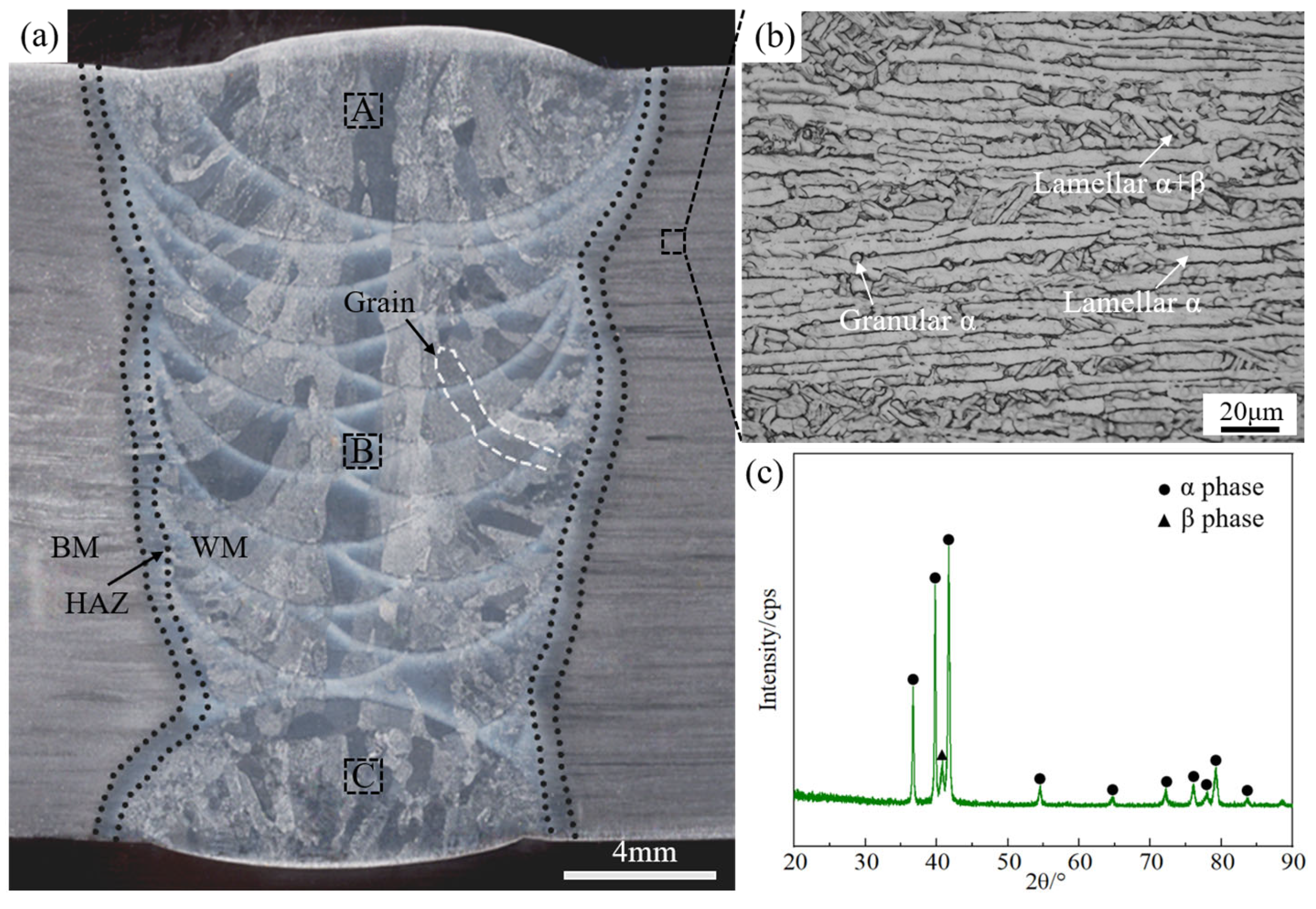
3.2. Weld Morphology and Microstructure

By changing the position of laser, arc and filler wire, the weld was shifted to the sidewall as a whole, and the heat on the sidewall was increased, which promoted the fusion of titanium alloy narrow-gap welding. The weld morphology can be classified into two types: concave and convex. When the parameters of the convex weld were used for welding, the lack of fusion might occur during the next pass of filled welding. However, the joint with better fusion can be obtained by filled welding with concave welding parameters [25].
In order to verify the effect of the above technology, the narrow-gap welding of 24 mm-thick TC4 titanium alloy was carried out, where D1 and D2 were 2 mm and 0.5 mm, respectively. The welding process consists of bottom welding, filled welding, and cover welding. In order to achieve a good welding effect, the method of alternating offset on both sides between each pass was adopted in the filled welding. Figure 8 shows the surface morphology of the front and back welded joints of the plate after welding. The welded joint surface appeared silvery white and free from defects such as air pollution, indicating a well-protected welding process.
Figure 9a shows the macroscopic morphology of the welded joint cross-section. The welds are alternately formed and each alternating layer formation has a concave morphology. There are no defects such as pores and incomplete fusion in the joint, which can be divided into three regions: base metal (BM), heat-affected zone (HAZ), and weld material (WM). The microstructure of these regions differs significantly. The welding-layers fusion line is clearly visible in the WM of the welded joint. The titanium alloy has poor thermal conductivity, causing the grains to grow quickly into large columnar crystals in the opposite direction of the temperature gradient. Some of these crystals grow across the layer due to the thermal effect of subsequent welding, and they continue to grow in the previous orientation [26]. The HAZ zone was relatively narrow, which reflects the advantages of using a small heat input in narrow-gap, low-power pulsed laser-TIG hybrid welding.
No significant difference was found in the microstructure of TC4 titanium alloy BM in different positions, as shown in Figure 9b. The BM structure, as seen in Figure 9c, was the typical α + β dual-phase structure after hot rolling. It consisted of a large number of extruded α phase matrices, as well as the β phase structure distributed between the grains. The β phase had not been completely transformed, and the α phase was contained in the β phase. In general, the lamellar structure can improve the fracture toughness of the material. Additionally, the β phase, which contains V element, contributes to good plasticity and toughness [27]. The base metal exhibits good mechanical properties due to the synergistic effect of the lamellar α phase and the intergranular β phase.
During the welding process, the temperature of the molten pool metal was higher than that of the base metal, resulting in a significant temperature gradient between them. This difference in heating led to variations in the microstructure of the Heat Affected Zone (HAZ) at different locations [28]. According to the microstructure characteristics, the HAZ is divided into two regions: HAZ near the base metal (BM) and HAZ near the weld metal (WM). As shown in Figure 10a, the HAZ near the BM was located further away from the center of the heat source, was less heated, and retained the BM matrix. The α phase had a blocky structure, with part of it transforming into the β phase. During cooling, the β phase formed acicular α′ martensite without any noticeable β grain boundary. In Figure 10b, the temperature of the HAZ near the WM was higher than the β phase transition temperature. Due to the faster cooling rate, the β phase underwent a transition structure, forming fine acicular α′ martensite [29].
Because the previous pass will be affected by the thermal cycle of the subsequent welding process, and the cooling rate of the weld zone varied with thickness, the result is differences in the microstructure between layers [30]. Microstructure observation was conducted on the top, middle, and bottom regions of the filling layer (A–C areas in Figure 9), as shown in Figure 11a–c. Figure 11d displays the XRD test results of the filling layer’s WM. The three regions showed high contents of α’ phase and few high temperature residual β phase. The main strong peaks of the three regions were consistent, with slightly different peak width and strength. The α’ peak of the middle weld of the filling layer was the strongest, and the α’ peak of the bottom weld was the weakest. Figure 11 shows that there was little difference in the microstructure of the weld metal (WM) between different layers. The microstructure was mainly composed of acicular α’ martensite in β columnar grains and granular α. During the heating process under the laser-TIG hybrid heat source, the microstructure of the WM underwent β phase transformation and grew rapidly. During the rapid cooling process, the cooling rate of WM exceeded the critical rate of martensitic transformation, the high temperature β phase could not transform into the original α phase, but instead transformed into the α’ phase. The middle weld was significantly affected by the welding thermal cycle, resulting in further refinement of the acicular martensite and a more uniform distribution within the grain. Additionally, the granular α phase precipitated more. The top weld had the fastest heat dissipation and the shortest high temperature residence time. Therefore, compared with the bottom weld, it had smaller organization.

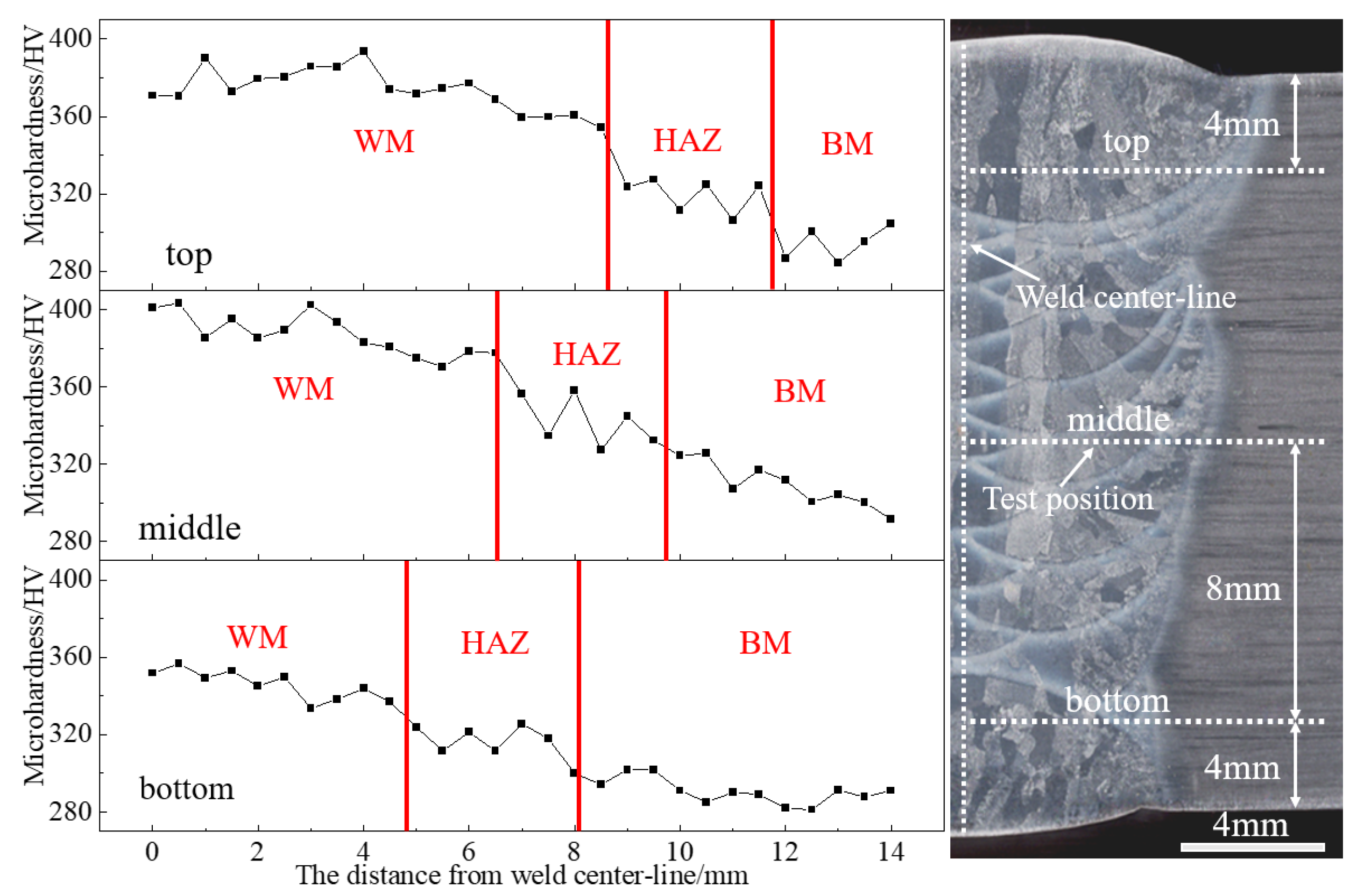
3.3. Microhardness of the Joint

The microhardness order of each phase in the TC4 titanium alloy is α′ > α > β [31]. Figure 12 displays the microhardness distribution of the top, middle, and bottom regions of the welded joint. The microhardness trend of the three parts was similar, decreasing from the weld center line to the base metal. The average microhardness of the base metal was the lowest due to the high content of the β phase. The microhardness of the HAZ and WM was higher than that of the base metal. During the welding process, a large amount of α’ martensite formed in the HAZ and WM, causing the dissolution of Al elements and the generation of a large amount of solute gas atoms. These atoms interacted with dislocations and hindered their movement, resulting in improved strength and microhardness. The microhardness of WM was the highest due to its mainly α’ composition and relatively uniform distribution of α′. The microhardness of the HAZ varied significantly due to its complex microstructure.

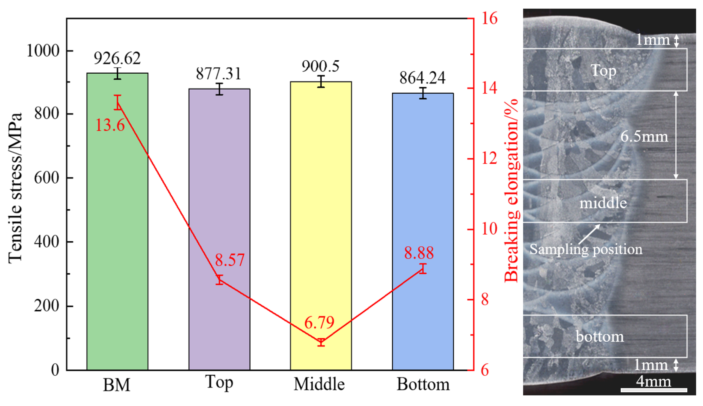
3.4. Tensile Properties of the Joint

Figure 13 shows the tensile properties of the base metal and the top, middle, and bottom parts of the welded joint. The sampling position of the tensile specimen was the same as that of the microhardness test. All of the tensile specimens were broken at the weld. The middle of the welded joint exhibited the highest tensile strength, while the bottom part had the lowest. On average, the strength of the welded joint was 95.05% of the base metal, and the average elongation was 59.42% of the base metal. The tensile strength of the welded joint can be increased through martensite strengthening of the α’ phase, dispersion strengthening of the granular α phase, and solid solution strengthening of the alloying elements in the weld [32]. However, this may lead to a decrease in the plasticity of the welded joint. Shear occurs between adjacent grains under external forces, subjecting each grain to the force of adjacent grains. The Hall-Petch formula states that smaller grain sizes result in larger interface areas, stronger hindering effects on dislocation movement, and greater deformation resistance.
σ s = σ 0 + k d 1 2 ,
where σ0 is the frictional resistance caused by dislocation movement or internal stress, k is a constant related to the material type and grain size, and d is the average diameter of grains.
The weld located in the middle of the joint underwent a welding thermal cycle, which continuously refined the grains and martensite, resulting in the finest and most uniform microstructure and the highest strength. The top weld had the fastest heat dissipation, but it was not affected by the welding thermal cycle, and the microstructure was slightly coarse. The tensile strength conforms to the welding-layers microstructure law.
Figure 14 shows the microscopic tensile fracture. The BM exhibited numerous deep dimples in the tensile fracture, as shown in Figure 14a. The specimen underwent micro-hole necking fracture and micro-crack formation under external tension until it broke, which is a typical example of ductile fracture. The fracture in the middle of the welded joint consisted of dimples with quasi-cleavage planes, resulting in a ductile-brittle mixed fracture, as shown in Figure 14b. Figure 14c shows the fracture morphology of the top part of the joint; in addition to the ductile fracture area, acicular traces were observed in some areas. The cracks were caused by the brittle phase inside the grains and propagated through the grains, resulting in fracture. The fracture exhibited clear cleavage steps due to varying grain plane heights. The top section of the welded joint displayed a mixed ductile-brittle fracture, while the bottom section had shallow, dense, and fine dimples, indicating a ductile fracture.

4. Conclusions

This paper proposes a technique of adjusting the spatial position of laser, arc and filler wire to perform narrow-gap laser-TIG hybrid welding of titanium alloy, aiming to overcome the limitations of traditional welding methods for large and complex components. The welding process was stable, and it solved the problem of poor fusion of sidewall and welding-layers. The main conclusions are made as follows:
(1)
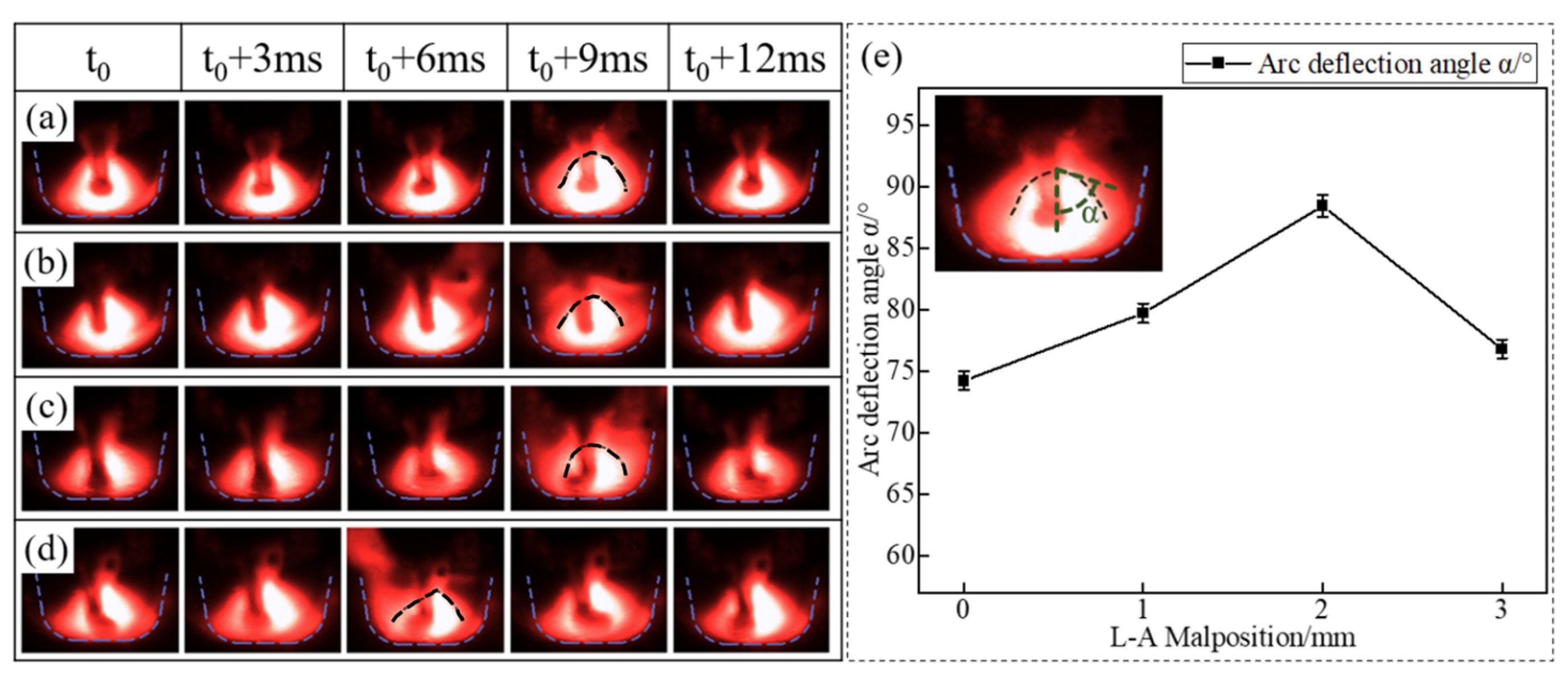
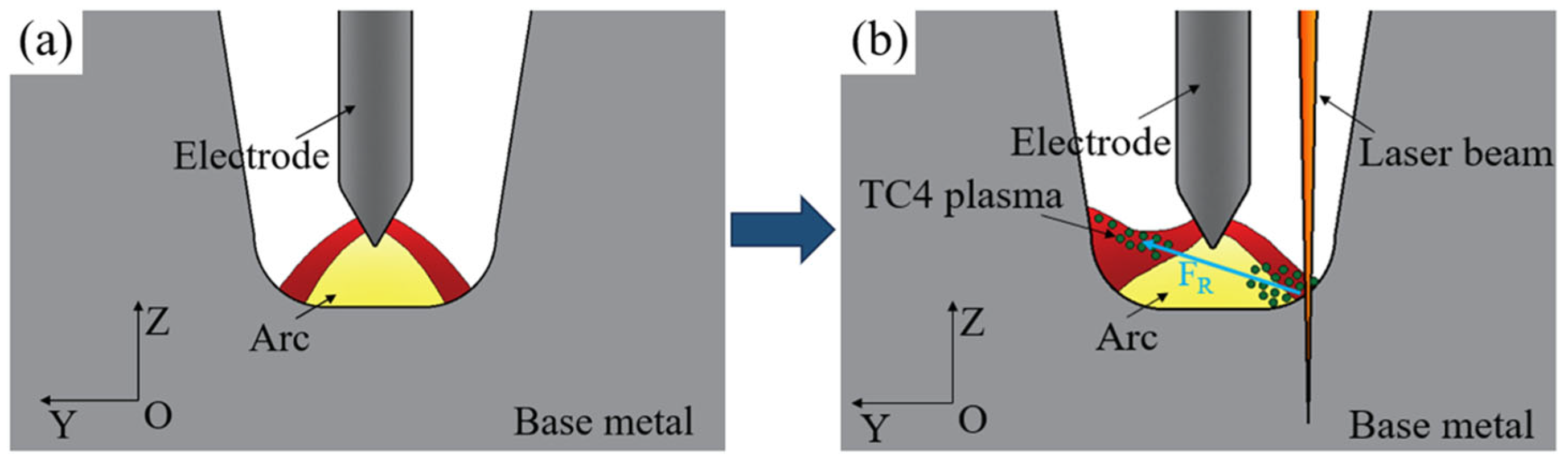
The arc was stably deflected under the induction of the laser after adjusting the laser-arc malposition. Increasing the laser-arc malposition from 0 mm to 2 mm resulted in a 16.06% increase in the arc deflection angle. This improved the problem of poor sidewall fusion by allowing the arc heat to act more effectively on the sidewall of the laser side.
(2)
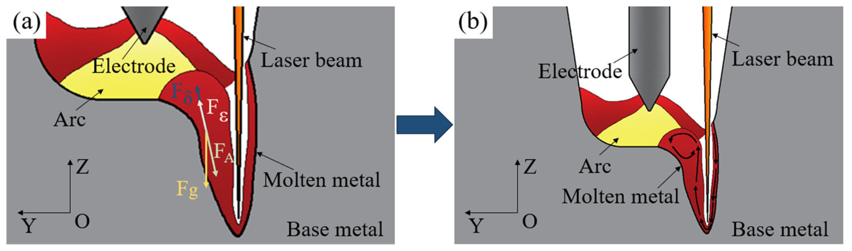
By increasing the filler wire-arc malposition, an inclined weld could be obtained, which was helpful for interlayer fusion. At the same time, the weld was shifted to the sidewall as a whole, improving the transition between the weld and the groove root and suppressing the formation of pores.
(3)
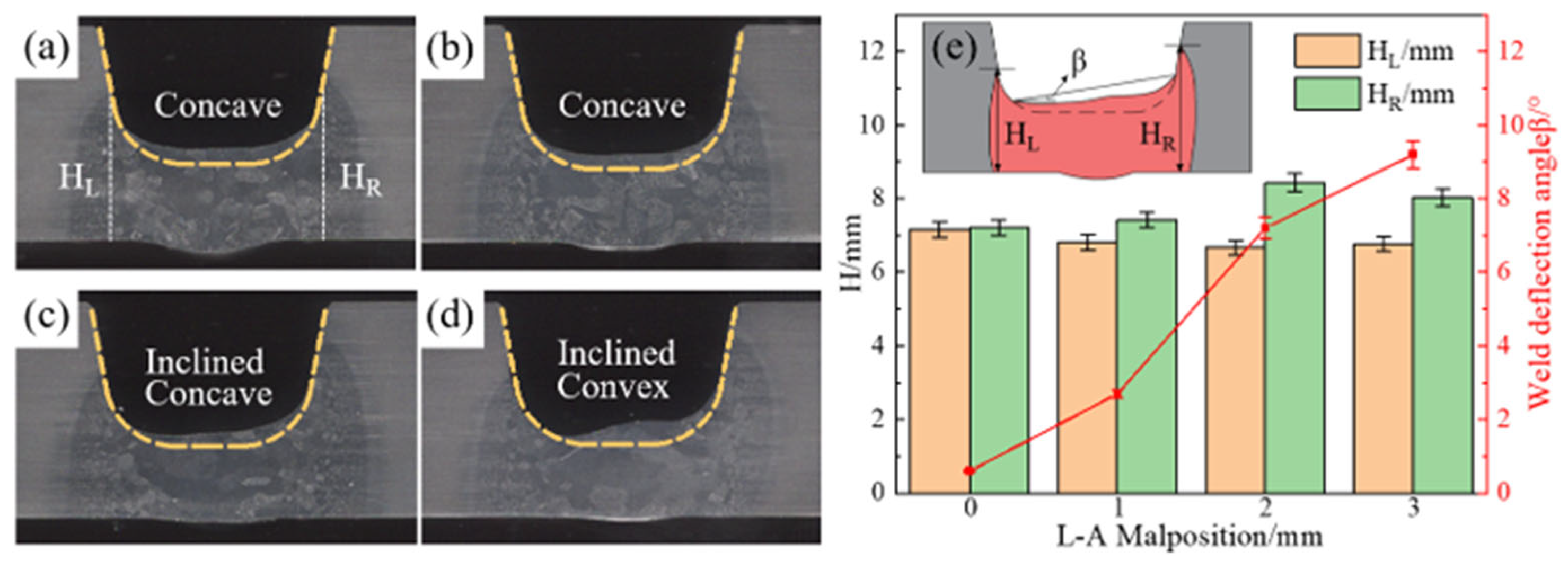
The weld morphology could be divided into two types: concave and convex. In order to obtain a well-fused joint, it is recommended to select concave welding parameters for filled weld. A well-formed concave weld can be achieved with the laser-arc malposition of 1.0–2.0 mm and the filler wire-arc malposition of 0–0.5 mm.
(4)
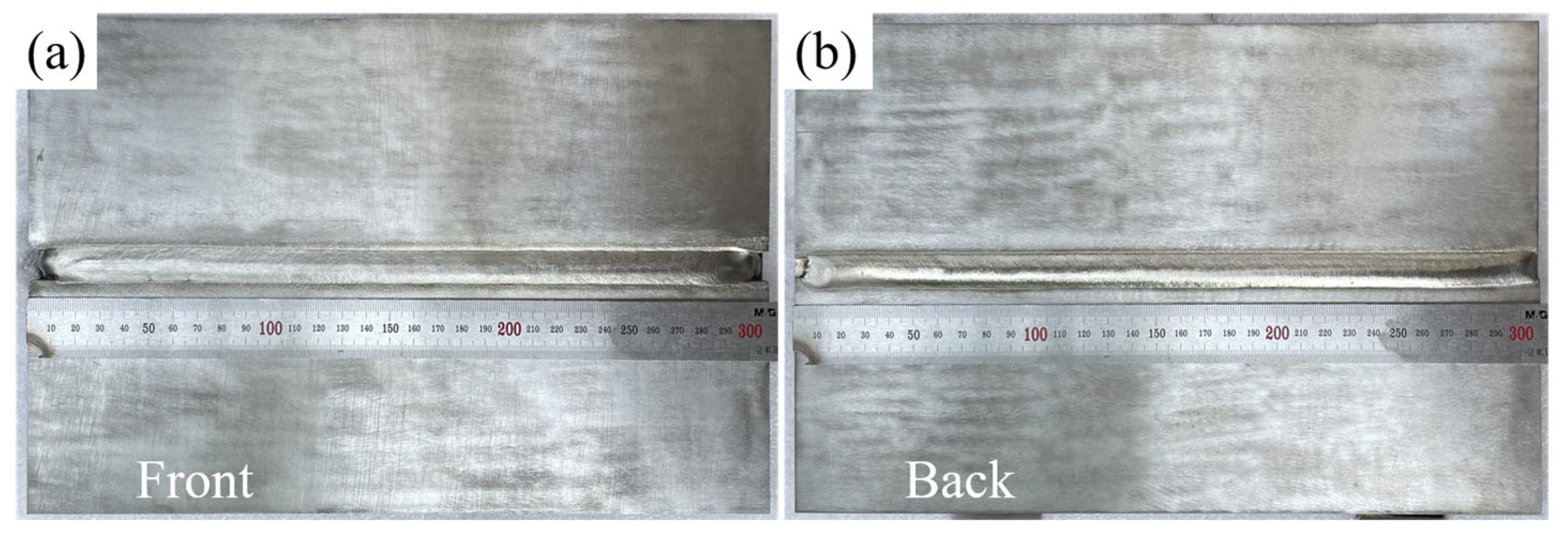
Narrow-gap laser-TIG hybrid welding was used to weld a 24 mm-thick titanium alloy. The sidewall and welding-layer of the joint were effectively fused, resulting in an average tensile strength of 95.05% of the base metal.

Author Contributions

Conceptualization, Z.X., L.L. and Q.L.; methodology, Z.X., H.W. and Q.L.; data curation, Z.X. and X.L.; writing—original draft preparation, Z.X.; writing—review and editing, G.S., Q.L., L.L. and X.L.; supervision, G.S., H.W. and L.L.; funding acquisition, G.S. and L.L. All authors have read and agreed to the published version of the manuscript.

Funding

This paper was funded by the Ministry of Science and Technology (Funding number 2022YFB4600900).

Data Availability Statement

The original contributions presented in the study are included in the article, further inquiries can be directed to the corresponding authors.

Conflicts of Interest

The authors declare no conflict of interest.

References

  1. Kumar, A.; Kumar, N.; Mahto, M.K.; Yadav, S.D.; Vashista, M.; Yusufzai, M.Z.K. Impression creep behaviour of different zones of pulsed gas tungsten arc welded Ti-6Al-4V alloy. Mater. Today Commun. 2023, 36, 106722. [Google Scholar] [CrossRef]
  2. Schneider, A.; Gumenyuk, A.; Lammers, M.; Malletschek, A.; Rethmeier, M. Laser Beam Welding of Thick Titanium Sheets in the Field of Marine Technology. Phys. Procedia 2014, 56, 582. [Google Scholar] [CrossRef]
  3. Chen, J.; Pan, C. Welding of Ti-6Al-4V alloy using dynamically controlled plasma arc welding process. Trans. Nonferrous Met. Soc. China 2011, 21, 1506. [Google Scholar] [CrossRef]
  4. Kumar, K.; Masanta, M. Effect of reducing heat input on autogenous TIG welding of Ti-6Al-4V alloy. Trans. Nonferrous Met. Soc. China 2023, 33, 3712. [Google Scholar] [CrossRef]
  5. Liu, X.; Ling, W.; Li, Y.; Wang, J.; Zhan, X. Interlaminar Microstructure and Mechanical Properties of Narrow Gap Laser Welding of 40-mm-Thick Ti-6Al-4V Alloy. Materials 2022, 15, 7742. [Google Scholar] [CrossRef] [PubMed]
  6. Yang, T.; Liu, J.; Zhuang, Y.; Xu, D. Micro-crystallographically unraveling strength-enhanced behaviors of the heavy-thick Ti-6Al-4V welded joint. Mater. Charact. 2022, 188, 111893. [Google Scholar] [CrossRef]
  7. Safdar, A.; Wei, L.-Y.; Snis, A.; Lai, Z. Evaluation of microstructural development in electron beam melted Ti-6Al-4V. Mater. Charact. 2012, 65, 8. [Google Scholar] [CrossRef]
  8. Wu, M.; Xin, R.; Wang, Y.; Zhou, Y.; Wang, K.; Liu, Q. Microstructure, texture and mechanical properties of commercial high-purity thick titanium plates jointed by electron beam welding. Mater. Sci. Eng. A 2016, 677, 50. [Google Scholar] [CrossRef]
  9. Bieliszczuk, K.; Zręda, J.; Chmielewski, T.M. Influence of Cylindrical Cells Surface Cleaning by Means of Laser Ablation on Wedge Wire Bonding Process. Coatings 2024, 14, 445. [Google Scholar] [CrossRef]
  10. Ramakrishna, V.S.M.R.; Amrutha, P.H.S.L.; Rashid, R.A.R.; Palanisamy, S. Narrow gap laser welding (NGLW) of structural steels—A technological review and future research recommendations. Int. J. Adv. Manuf. Technol. 2020, 111, 2277. [Google Scholar] [CrossRef]
  11. Guo, W.; Crowther, D.; Francis, J.A.; Thompson, A.; Li, L. Process-parameter interactions in ultra-narrow gap laser welding of high strength steels. Int. J. Adv. Manuf. Technol. 2016, 84, 2547. [Google Scholar] [CrossRef]
  12. Wan, L.; Huang, Y.; Lv, S.; Huang, T.; Li, C.; Feng, J. Narrow-gap tungsten inert gas welding of 78-mm-thick Ti-6Al-4V alloy. Mater. Sci. Technol. 2016, 32, 1545. [Google Scholar] [CrossRef]
  13. Li, F.; Liu, Y.; Ke, W.; Jin, P.; Kong, H.; Chen, M.; Sun, Q. A novel pathway to weld forming control and microstructure improvement of duplex stainless steel via alternating magnetic field. J. Manuf. Process. 2022, 80, 581. [Google Scholar] [CrossRef]
  14. Ding, L.; Qin, B.; Ge, K.; Zeng, Z.; Vladyslav, K.; Li, F.; Zhang, Y.; Wang, H. Microstructures and Mechanical Properties of Thick Ti-6Al-3Nb-2Zr-1Mo Joint by Magnetron-Controlled Narrow Gap TIG Welding. Met. Mater. Int. 2023, 29, 2304. [Google Scholar] [CrossRef]
  15. Long, J.; Zhang, L.-J.; Zhuang, M.-X.; Bai, L.-A.; Na, S.-J. Narrow-gap laser welding with beam wobbling and filler wire and microstructural performance of joints of thick TC4 titanium alloy plates. Opt. Laser Technol. 2022, 152, 108089. [Google Scholar] [CrossRef]
  16. Liu, Q.; Wu, D.; Wang, Q.; Zhang, P.; Yan, H.; Sun, T.; Li, R. Progress and perspectives of joints defects of laser-arc hybrid welding: A review. Int. J. Adv. Manuf. Technol. 2023, 130, 111. [Google Scholar] [CrossRef]
  17. Gui, H.; Zhang, K.; Li, D.; Li, Z. Effect of relative position in low-power pulsed-laser–tungsten-inert-gas hybrid welding on laser-arc interaction. J. Manuf. Process. 2018, 36, 426. [Google Scholar] [CrossRef]
  18. Shi, J.; Zhou, Y.; Liu, L. Application of Pulsed Laser-TIG Hybrid Heat Source in Root Welding of Thick Plate Titanium Alloys. Appl. Sci. 2017, 7, 527. [Google Scholar] [CrossRef]
  19. Liu, L.; Shi, J.; Hou, Z.; Song, G. Effect of distance between the heat sources on the molten pool stability and burn-through during the pulse laser-GTA hybrid welding process. J. Manuf. Process. 2018, 34, 697. [Google Scholar] [CrossRef]
  20. Liu, L.M.; Yuan, S.T.; Li, C.B. Effect of relative location of laser beam and TIG arc in different hybrid welding modes. Sci. Technol. Weld. Join. 2012, 17, 441. [Google Scholar] [CrossRef]
  21. Lang, Q.; Zhang, Z.; Wang, Z.; Song, G.; Khan, M.S.; Liu, L. Consumable-free dissimilar joining of Mg to steel using a laser-arc hybrid heat source. Mater. Charact. 2023, 204, 113134. [Google Scholar] [CrossRef]
  22. Shi, J.; Song, G.; Wang, H.; Liu, L. Study on weld formation and its mechanism in laser-TIG hybrid welding with filler wire of a titanium alloy. J. Laser Appl. 2018, 30, 032004. [Google Scholar] [CrossRef]
  23. Fan, X.; Qin, G.; Jiang, Z.; Wang, H. Comparative analysis between the laser beam welding and low current pulsed GMA assisted high-power laser welding by numerical simulation. J. Mater. Res. Technol. 2023, 22, 2549. [Google Scholar] [CrossRef]
  24. Liu, J.; Yang, T.; Zhuang, Y.; Huang, M.; Su, X.; Dong, S. Unveiling arc deflection instability in narrow gap laser-arc hybrid welding of thick Ti-6Al-4V plate. J. Manuf. Process. 2023, 104, 87. [Google Scholar] [CrossRef]
  25. Yu, J.; Cai, C.; Xie, J.; Huang, J.; Liu, Y.; Chen, H. Weld formation, arc behavior, and droplet transfer in narrow-gap laser-arc hybrid welding of titanium alloy. J. Manuf. Process. 2023, 91, 44. [Google Scholar] [CrossRef]
  26. Yang, T.; Xu, D.; Chen, W.; Yang, R.; Lv, S. Microstructure evolution and deformation resistance of heavy-thickness Ti-6Al-4V narrow-gap welded joints. Mater. Lett. 2019, 250, 116. [Google Scholar] [CrossRef]
  27. Guo, P.; Zhao, Y.; Zeng, W.; Hong, Q. The effect of microstructure on the mechanical properties of TC4-DT titanium alloys. Mater. Sci. Eng. A 2013, 563, 106. [Google Scholar] [CrossRef]
  28. Fan, H.; Zhou, P.; Li, J.; Huang, J.; Ni, Y.; Hui, Y. Microstructure and Mechanical Properties of Arc Zone and Laser Zone of TC4 Titanium Alloy Laser–TIG Hybrid Welded Joint. Metals 2022, 12, 1854. [Google Scholar] [CrossRef]
  29. NFang, N.; Guo, E.; Huang, R.; Yin, L.; Chen, Y.; Zeng, C.; Cao, H.; Zou, J.; Xu, K. Effect of welding heat input on microstructure and properties of TC4 titanium alloy ultra-narrow gap welded joint by laser welding with filler wire. Mater. Res. Express 2021, 8, 16511. [Google Scholar]
  30. Su, X.; Tao, W.; Chen, Y.; Fu, J. Microstructure and Tensile Property of the Joint of Laser-MIG Hybrid Welded Thick-Section TC4 Alloy. Metals 2018, 8, 1002. [Google Scholar] [CrossRef]
  31. Hou, N.; Zhang, Y.; Wang, M.; Huang, S.; Kong, X. Discrete characteristic and edge effect during subsurface microhardness measurement of Ti-6Al-4V alloy. Mater. Res. Express 2022, 9, 116503. [Google Scholar] [CrossRef]
  32. Li, P.; Li, L.; Tang, L.; Wang, L.; Xu, J.; Dong, L.; Mao, X.; Liu, Y.; Zhang, Y. Micron-sized SiC particles reinforced TC4 composites: Mechanical properties and strengthening mechanisms. Mater. Today Commun. 2024, 38, 108147. [Google Scholar] [CrossRef]
Figure 1. Schematic diagram of: (a) welding system; (b) Y-O-Z plane diagram; (c) the dimensions of the tensile sample.
Metals 14 00510 g001
Figure 2. Arc behavior under different D1: (a) 0 mm; (b) 1 mm; (c) 2 mm; (d) 3 mm; (e) arc action angle comparison.
Metals 14 00510 g002
Figure 3. Schematic diagram of arc behavior affected by plasma at D1 of 3 mm: (a) arc behavior without laser; (b) arc behavior under laser action.
Metals 14 00510 g003
Figure 4. Cross-section morphology under different D1: (a) 0 mm; (b) 1 mm; (c) 2 mm; (d) 3 mm; (e) cross-section morphology comparison.
Metals 14 00510 g004
Figure 5. Schematic diagram of molten pool at D1 of 3 mm: (a) force condition of the molten pool; (b) Marangoni convection in the molten pool.
Metals 14 00510 g005
Figure 6. Droplet transfer under different D2: (a) 0 mm; (b) 0.5 mm; (c) 1 mm; (d) 1.5 mm; (e) the force on the droplet.
Metals 14 00510 g006
Figure 7. Cross-section morphology under different D2: (a) 0 mm; (b) 0.5 mm; (c) 1 mm; (d) 1.5 mm; (e) cross-section morphology comparison.
Metals 14 00510 g007
Figure 8. Surface morphology of welded joint: (a) front weld; (b) back weld.
Metals 14 00510 g008
Figure 9. (a) Macroscopic morphology of welded joint cross-section; (b) microstructure of BM; (c) XRD pattern of BM.
Metals 14 00510 g009
Figure 10. Microstructure of HAZ: (a) HAZ near BM; (b) HAZ near WM.
Metals 14 00510 g010
Figure 11. (a) Microstructure of top WM; (b) microstructure of middle WM; (c) microstructure of bottom WM; (d) XRD patterns of WM.
Metals 14 00510 g011
Figure 12. Microhardness of welded joints at different positions.
Metals 14 00510 g012
Figure 13. Tensile properties of BM and welded joint.
Metals 14 00510 g013
Figure 14. Tensile microscopic fracture: (a) BM; (b) middle welded joint; (c) top welded joint; (d) bottom welded joint.
Metals 14 00510 g014
Table 1. Chemical composition of TC4 titanium alloy (wt%).
TiAlVFeOCNH
Bal.5.5–6.83.5–4.5≤0.30≤0.20≤0.10≤0.05≤0.015
Table 2. Welding parameters.
PL (W)I (A)VW (mm/min)VF (m/min)
300–500150–200150–5001.0–3.0
Table 3. Experimental parameters.
PL (W)I (A)VW (mm/min)VF (m/min)D1 (mm)D2 (mm)
3501802001.50–3.00
Table 4. Experimental parameters.
PL (W)I (A)VW (mm/min)VF (m/min)D1 (mm)D2 (mm)
3501802001.52.00–1.5
Disclaimer/Publisher’s Note: The statements, opinions and data contained in all publications are solely those of the individual author(s) and contributor(s) and not of MDPI and/or the editor(s). MDPI and/or the editor(s) disclaim responsibility for any injury to people or property resulting from any ideas, methods, instructions or products referred to in the content.

