
Microstructure Formation and Its Effect on Mechanical Properties for Duplex Stainless Steel 2205 Plasma Arc Welded Joint

1
College of Mechanical and Electronic Engineering, Shandong University of Science and Technology, Qingdao 266590, China
2
Shandong Hengtong Expansion Joint Manufacturing Co., Ltd., Tai’an 271000, China
3
College of New Energy, China University of Petroleum (East China), Qingdao 266580, China
*
Author to whom correspondence should be addressed.
Metals 2024, 14(1), 68; https://doi.org/10.3390/met14010068
Submission received: 11 November 2023
/
Revised: 11 December 2023
/
Accepted: 4 January 2024
/
Published: 6 January 2024
(This article belongs to the Special Issue New Technology of Welding/Joining of Metallic Materials)
Abstract
:The control of phase balance has always been a tough challenge for the welding of duplex stainless steel, which heavily restricts its optimal serving performance in engineering. The microstructure development and mechanical characteristics of SAF2205 plasma arc welded joints were thoroughly examined in this paper. It was proven that the phase balance can be well controlled by plasma arc welding, and the austenite content of the welded joints was about 60%. Despite successful phase control, there was still grain coarsening and distortion; i.e., at the center of the welded zone, the gain size was about eight times that of the base metal, and the austenite was mainly in the form of grain boundary austenite and intragranular austenite, while more Widmanstatten austenites were found in the heat-affected zone. In addition, a transition region between the heat affected zone and the center exhibited columnar ferritic grains. Furthermore, the plasticity and toughness of the welded joints were significantly decreased, especially the elongation in the longitudinal direction, which is about 10% lower than that of the base metal, and transversal tensile strength remained comparable to the base metal, with only a slight reduction in longitudinal tensile strength. Lastly, the formation mechanism of microstructure and its correlation with mechanical properties were revealed. This investigation offers valuable insights into the structural integrity of duplex stainless steel welded joints in engineering applications.
1. Introduction
Duplex stainless steel (DSS), characterized by the coexistence of austenite (γ) and ferrite (α), amalgamates the advantages of single-phase stainless steels. These advantages include superior plastic toughness compared to ferritic stainless steel and more than double the yield strength of austenitic stainless steel, coupled with robust resistance to stress corrosion [1]. Therefore, it is widely employed in diverse engineering environments, such as petrochemical equipment, energy and power engineering, and marine engineering [2,3]. The equal ratio (50% each) is an essential precondition for optimizing the service performance of DSS [4]. However, the welding process is easily disturbed due to the rapidly changing and heterogeneous thermal cycle, which may also lead to the precipitation of brittle phases [5].
Consequently, it is challenging to identify an appropriate welding method that would regulate the phase ratio and mechanical properties of the DSS welded joints. Numerous investigations have been performed to analyze the microstructure formation of DSS during the welding process in order to better control the phase balance of austenite and ferrite. If the welding process receives excessive or insufficient energy input, it may lead to an imbalance of austenite or ferrite in duplex stainless steel. Various welding methods, including friction stir welding, argon arc welding, laser welding, and submerged arc welding, have been investigated to analyze the microstructure formation of DSS during welding. Friction stir welding (FSW) has been found to create welded joints featuring grain refinement, but an increase in ferrite content was also observed. However, this welding technique imposes severe plastic deformation and frictional heat on the material, which can lead to the precipitation of brittle phases in the stirred zone and heat-affected zone, ultimately affecting the mechanical properties [6,7,8]. Compared to the solid-state welding method, tungsten argon arc welding is the most frequently used fusion welding process in engineering. It is commonly employed in the dissimilar welding of duplex stainless steel, and for plates with a thickness exceeding 3 mm, the welding must be carried out in multiple passes. The welded joints produced through tungsten inert gas welding (TIG) have a substantial heat-affected zone where there is excess ferrite, but the austenite ratio may approach to 70% at the welded zone due to multipass thermal cycles [9,10,11], as shown in Figure 1a. Laser beam welding (LBW) enables the management of the cross-sectional area of the heat-affected zone in the welded joint by regulating the energy input of the keyhole. This leads to variations in the austenite morphology and proportion as a result of the loss of N elements in the joint, subsequently influencing its mechanical properties [12,13]. At the same time, DSS welded joints produced by the LBW method frequently have an excess of ferrite, as shown in Figure 1b. Furthermore, it has been found that laser welding exhibits differing degrees of susceptibility to phase transition-induced plasticity (YRIP), solid-state phase transition (PT) volume effects, and hydrogen embrittlement [14,15]. While welding duplex stainless steel using submerged arc welding, a two-phase ratio of the welded joints can be achieved by using wire with a higher Ni content than the base material, ranging between 2 and 4% [16]. But the utilization of such wire also results in the occurrence of brittle deposition of the phase in the heat-affected zone [17,18,19].
Plasma arc welding (PAW), as a fusion welding process, employs the high-energy-density plasma arc beam as the heat source for welding [21]. It is commonly used in demanding and high efficiency applications such as aircraft, rockets, and structural steel [22]. Hole-locking plasma arc welding provides many advantages compared to previously discussed welding methods, including high energy density, low heat input, and strong arc penetration. It exhibits significant progress for the plates with a thickness of 12 mm or less in one double-sided welding without beveling or filling wire. Furthermore, for the DSS, the PAW method of filler wire addition has been proven to avoid the loss of elements in the material and produce narrower, high-quality, homogeneous welds and virtually heat-affected zone free duplex stainless steel welds compared to laser beam welding. This may allow for a balanced ratio of the two phases in the joints. However, what still remains to be understood is the process of microstructure development and how it affects the mechanical properties of DDS PAW welded joints.
Therefore, this study firstly manufactured the DSS welded joints with a thickness of 5 mm by the PAW method. Subsequently, a detailed observation of the microstructure was carried out by optical microscopy; meanwhile, the mechanical tests including the uniaxial tensile tests and the measurement of microhardness and impact toughness were performed. Lastly, the microstructure formation mechanism and the correlation between mechanical properties and microstructure were discussed extensively. The unique contribution of this study is the identification that, despite an effective phase ratio control of 2205 duplex steel through plasma welding and preservation of its favorable mechanical properties, the persisting challenge of non-uniform distribution and coarse-grained joints has been uncovered. Furthermore, it has been found that the elongation of the welded joint is 10% lower than that of the base metal and that the tensile strength in the longitudinal direction has slightly decreased. Therefore, it is advisable to avoid tensile stresses in this direction as much as possible in practical applications. This investigation offers valuable insights into the challenges of the structural integrity of the DSS welded components, and its practical relevance in engineering production applications is significant.
2. Experimental Procedures
2.1. Manufacture of Welded Joints by Plasma Arc Welding
The duplex stainless steel SAF2205 (DSS 2205) plate with a thickness of 5 mm was evaluated as the base metal in this study, whose chemical composition is listed in Table 1. Meanwhile, as introduced earlier, ferritization is easily observed for such welding methods, which have a concentrated energy density. Therefore, differently from usual plasma arc welding with no filled metal, the ER2209 wire with relatively high austenite stabilizing element Ni was employed, as listed in Table 1. In addition, a non-open beveled flat-plate butt weld form was considered. The experimental welding equipment is a lock-hole plasma arc welding machine produced by Shanghai Langzhi Welding Equipment (Shanghai, China). The welding process parameters are established through repetitive practice by Shandong Hengtong Expansion Joint Manufacturing Co. (Tai’an, China), as introduced in Table 2. The welding deformation was very small and can be ignored, and the depth of the molten pool was about 6 mm. No anomalies were detected by X-ray examination methods.
2.2. Microstructure Observation
The as-welded microstructure across the whole welded joints was observed by optical microscopy (OM). The small specimens at different characteristic zones were cut by using wire-cut technology, and the surface was grinded and polished using 400, 600, 1000, 1200, and 1500 mesh sandpaper. Then, the corrosive liquid with 1.5 g K2S2O5 + 15 mL HCl + 85 mL H2O was used for 10 s until the surface darkened. The corroded surface was immediately rinsed with water. Finally, the microstructural observation was achieved by using a 15 kV, 7 mm Zeiss scanning electron microscope. Scanning electron microscopy (SEM) was performed with a Hitachi SU3800 (Hitachi High-Tech Co., Tokyo, Japan).
2.3. Characterization of Mechanical Properties
To comprehensively understand the mechanical properties of DSS2205 PAW welded joints, a series of mechanical tests were carried out, including uniaxial tensile tests and the measurement of microhardness and impact toughness. Firstly, the sampling and detailed dimensions of tensile specimens are illustrated in Figure 2a. Note that to better analyze the strength of welded joints, the miniature specimens were prepared and divided into four categories based on the sampling direction and location, i.e., transversal one at welded joints (TWJ) (straight edge section contains weld seam and base metal), longitudinal one at welded joints (LWJ), transversal one at base metal (TBM), and transversal one at base metal (LBM). The detailed procedures of the tensile test follow the ISO 4136:2012 standard [23,24]. The displacement was controlled with a constant speed of 1 mm/min under the condition of 25 °C room temperature, while the load response was recorded by mechanical sensors.
Furthermore, the microhardness across the DSS2205 PAW welded joints was measured based on the American Welding Society (AWS B4.0:2007) Experimental Method for Hardness of Welded Joints [25] by using the FM-700 + SVDM-4R automatic micro-Vickers hardness tester. The path is displayed in Figure 2b. Note that it covers the upper end face by 3 mm from the weld zone to the base material zone, with every 0.2 mm hitting the point. The experiment utilized a working load of 1.931 N and a holding time of 15 s. In addition, the specimens for the measurement of impact toughness for both base metal and welded joints were prepared, as shown in Figure 2c. The Charpy impact test (V gap) method [26,27] was adopted on a JBN-300 pendulum impact tester. Note that the specimens were taken into three groups along the direction perpendicular to the weld from the weld area and the base metal [28].It is imperative to note the direction of the specimen placement during impact experiments.
3. Experimental Results
3.1. Microstructure Analysis
The microstructural characterization of the DSS2205 PAW welded joints at different locations is shown in Figure 3. The silver-white parts represent the austenite phase, while the dark-grey parts are the ferrite phase. It is clearly found that the distribution of microstructure across whole welded joints was seriously heterogeneous, particularly for the grain shape and size. At the base metal (BM, Figure 3a), the austenitic grains were discretely distributed within the ferritic matrix with the least grain size of about 30~120 μm. Then, at the head affected zone (HAZ, Figure 3b), the ferritic grains become equiaxed, but with a greater size of about 300 μm. At the same time, the austenite was observed mainly in the form of striped grain boundary austenite (GBA), which nuclear and grows along the ferritic grain boundaries. However, at the welded metal (WM, Figure 3d), the equiaxed ferritic grains become greater with the size of 600 μm, which leads to a lathier GBA. Not only that, there was a lot of tiny intragranular austenite (IGA), which is nuclear and grows inside the ferritic grain. In addition, there was a transition region between HAZ and WM, as shown in Figure 3c, where the ferritic grains became columnar with more Widmanstatten austenites (WA), which nucleated at one side of GBA and grew towards the inside of the ferrite. The phase ratio at different characteristic zones was calculated using the Image-Pro Plus 6.0 software package, as shown in Figure 4. It is obvious that the phase ratio was better controlled and approximated at 60/40% (austenite/ferrite), which means that this welding method is feasible [4].
3.2. Mechanical Performance
The tensile stress–strain diagrams as shown in Figure 5 were obtained from the uniaxial tensile experiments, and the tensile curves included the elastic, yielding, strengthening, and final fracture phases. It is obvious that the four specimens meet the SAF2205DSS tensile strength requirement (σb ≥ 620 MPa [29]). What should be more noteworthy is the change in anisotropy of tensile strength and plasticity. There was almost no difference between LBM and TBM in terms of tensile strength, while the transversal tensile strength was compared to that of BM, and the longitudinal tensile strength decreased slightly. Additionally, the elongation of the welded joint was 10% lower than that of the base material.
The morphology of the tensile fracture of DSS2205 at different locations is displayed in Figure 6. According to the tensile fracture of TWJ (Figure 6a), the river sample’s small cleavage planes of the longitudinal and transverse distribution and the fracture’s features of toughness fracture and quasi-cleavage fracture all differ in size and depth. The fracture characteristics of LWJ (Figure 6b) are similar to those of TWJ, but the difference is that the dimple of LWJ is larger. There are grain slippage characteristics and a number of quasi-cleavage planes in the dimples. The following two specimens’ tensile fracture surfaces exhibit indentations and tear edges [10], which are mixed tough–brittle fractures. Figure 6c,d show the BM fracture in two different directions. The distribution of the dimples within the fracture center is flat and evenly distributed, whereas those within the shear lip region surrounding the center are primarily parabolic in shape.
Hardness is a key indicator of the quality of welded joints and can represent the strength and resistance to wear [30]. Figure 7 shows the Vickers hardness measurement data for 2205DSS welded joints. Although the hardness value in the weld zone fluctuates dramatically, the overall hardness of the WM is higher than that of the BM. This is seen by the rising and falling trend of the hardness along the plate rolling direction. The weld metal fusion zone has the hardest material with a maximum value of 296.39 HV. The maximum hardness value at the center of welded joints is 280.63 HV with an average hardness of 275 HV. The BM has a hardness of roughly 265 HV.
The mechanical properties of the 2205DSS welded joints can be fairly described by the impact function quantity parameters discovered via impact experiments [31]. As shown in Figure 8, the impact toughness of the WM is lower than that of the BM; i.e., the average impact energy in the BM is 107.3 J, while the average impact energy in the WM is 86.7 J. When compared to the BM, the impact energy absorbed in the welded joint area is reduced by 20% to 30%.
Figure 9a demonstrates the impact fracture morphology of the BM. The typical toughness fracture characteristics can be clearly observed. It also illustrates the distribution of equiaxial dimples of various sizes on the fracture surface, as well as an insufficient amount of parabolic elongated dimples. A typical ductile–brittle mixed fracture can be seen in Figure 9b for the WM impact fracture morphology. That is the quasi-cleavage fracture of river-like characteristics [32], and the size of the depth of isometric dimples, with a staggered distribution of elongated dimples.
In conclusion, the post-weld organization can fulfill the real use and retain good mechanical properties. The heat-affected zone and the weld have harder surfaces than the underlying metal. Anisotropy was evident in tensile strength, while the addition of filler metal produced a weld with a higher percentage of austenite (60%), the experimental results were affected by the coarseness of some of the grains, causing the TWJ to exhibit varying degrees of elongation and loss of tensile strength. Although there was a noticeable drop in impact toughness compared to the base material, it was still within acceptable strength limits. Fracture analysis revealed that the welds exhibited a combination of ductile–brittle fracture.
4. Discussion
4.1. Formation Mechanism of Microstructure
The typical phase transformation process of DSS during welding is schematically described in Figure 10. Once the welding temperature exceeds the liquid phase line temperature of DSS (approximately 1470 °C), the welding area enters a state of high-temperature melting. As the cooling, the DSS is solidified into a complete ferritization (Stage I). Then, when the temperature is lower than approximately 1370 °C [33,34], some austenitic grains precipitate from the edges of ferrite grains as GBA (Stage II). Simultaneously, the subcooling degree of the weld meets the nucleation requirements for Widmanstätten austenite, resulting in the formation of a large amount of Weiss austenite nuclei at the ferrite/ferrite (α/α) interface and ferrite/austenite (α/γ) interface, which grow towards the interior of the ferrite [18] (Stage III). However, the significant variation in the cooling temperature gradient within the weld zone impedes the transformation of a substantial amount of ferrite into austenite, leading to the formation of IGA at the inside of ferrite when the subcooling is large enough (Stage IV) [35,36,37].
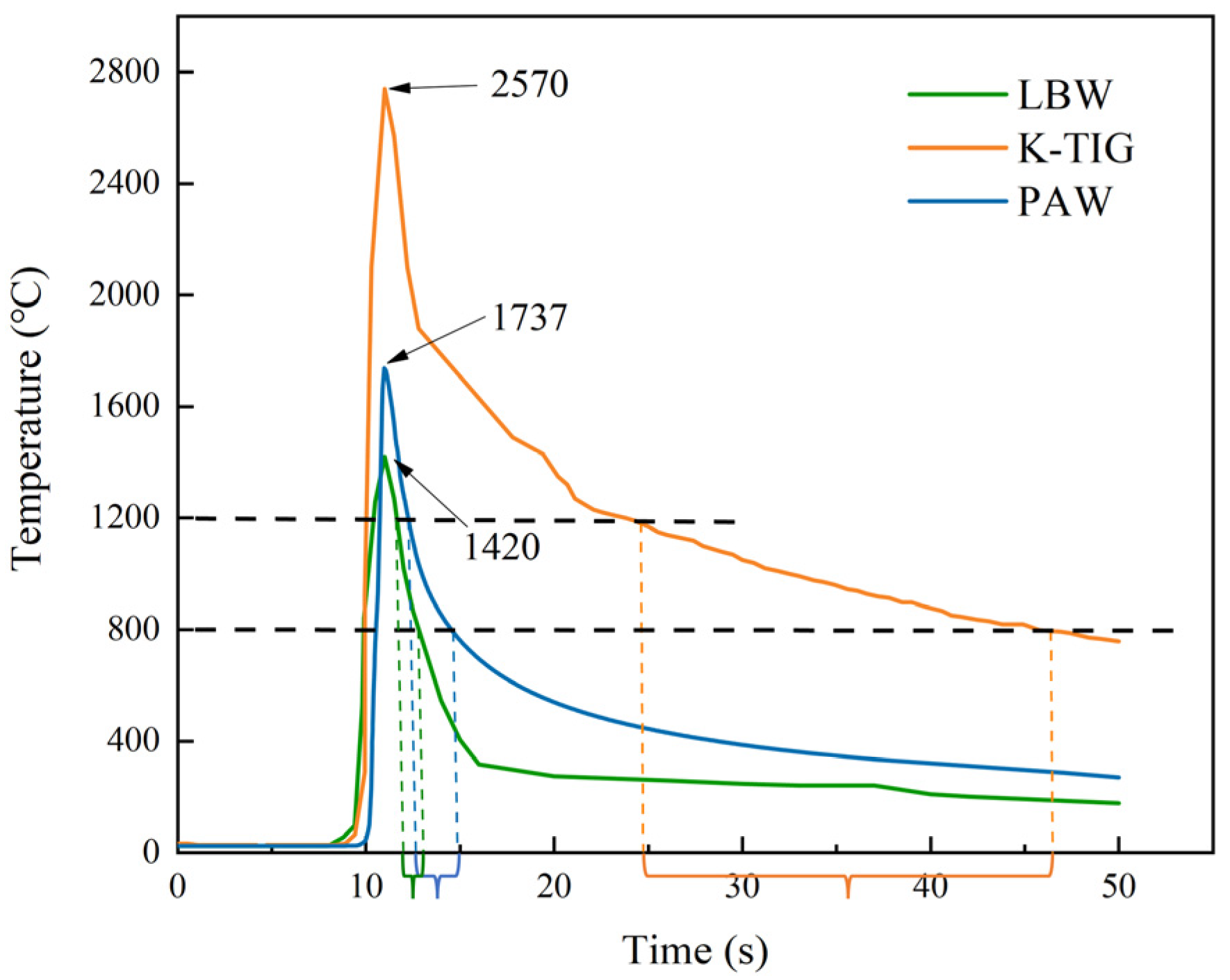
Although the phase transformation process was similar for different types of welding technologies, the final microstructural characteristics varied significantly with the thermal cycle. Figure 11 shows different typical thermal cycle curves for three types of welding technologies, which are from the welding of DSS2205 plate with a thickness of 5~8 mm, and utilizing actual welding data and simulation analyses in the Abaqus /CAE v2021 software package, weld temperature characteristics of the paw method are created. Note that the thermal cycle may be changed with the welding parameters even for the same welding technology, but the curves in Figure 11 are representative and commonly used. It is obvious that the peak temperature and cooling rate were significantly different. Balázs et al. [38] have reported that the length of time at a temperature range from 800 to 1200 °C plays a crucial role in the final phase ratio for the DSS welded joints. As shown in Figure 11, the K-TIG has the longest time of about 20 s, which leads to excess precipitation of austenite, as displayed in Figure 1a. However, for the LBW, it requires the least time of only 2 or 3 s, resulting in the ferritization of welded joints, as displayed in Figure 1b. The PAW method, at the middle of LAW and TIG methods, seems to be more suitable for the control of the phase ratio of DSS welded joints.
4.2. Correlation between Mechanical Properties and Microstructure
The joints become hard and brittle as a result of huge amounts of ferrite precipitating quickly when the temperature falls [41]. This reduces the tensile strength of the welded joints. The amount of heat input energy concentrated in PAW does not significantly slow down cooling at the weld area. As a result, favorable conditions are created for the precipitation of austenite and the mutual restraint of austenite and ferrite grains. Ferrite is inhibited by austenite, which has a higher stacking fault energy (SFE) [42]. Dual-phase 2205DSS welded joints are strengthened by the numerous fine austenitic structures that exist inside grain boundaries, which increase dislocation slip resistance [43].
As Figure 5 illustrates, it yields sufficient strength, as evidenced by the tensile mechanical properties of the joint in the weld direction. The tensile strength at the joints is comparable to that at the base. In contrast to the base material, the welded connections showed a noticeable decline in tensile characteristics throughout the rolling direction. In addition, the orientation of the grains in the weld zone was different from that of the BM, and the austenite was not entirely isotropic. The tensile strength was lower in the direction of rolling than in the perpendicular direction due to anisotropy [44], which was present. Furthermore, specimens’ tensile strength in the weld zone decreased in the rolling direction, which caused welded joints’ elongation to drop by around 20% in comparison to the BM [45].
Extended cooling times cause the joint to become stronger from the solid solution, which in turn encourages more hardness. Additionally, the strengthening of solid solutions can be aided by the addition of Ni to the welding consumables. The weld cools more quickly on the upper and lower surfaces than in the center because they are exposed to air throughout the welding process. Smaller grain sizes and the strengthening of solid solutions are the results. Higher energy is present in the WM, but uneven grain sorting prevents dislocations from passing between grain atoms, improving the material’s resistance to continuous slip. Without any disruptions to the grain structure, the grain distribution is uniform and ordered within the BM. Consequently, in comparison to both the WM and HAZ, the hardness level is somewhat lower in this area.
During the welding process, the fusion zone of the WM reaches a low-temperature peak and lingers for a considerable amount of time in the region with secondary phase and inclusion precipitation temperatures. The duplex stainless steel undergoes an eutectic transition at these temperatures: α → γ′ + σ. This causes secondary phases and inclusions to form in the steel, making it harder and more brittle and ultimately reducing impact toughness [46]. Impact hardness is simultaneously decreased by excessive austenite [47,48]. Duplex stainless steels go through a growth process from ferrite dominance to austenite re-nucleation in ferrite in the WM as a result of recrystallization [49]. At the same time, the sub crystalline merging process simultaneously increases grain-to-grain dislocation resistance, balancing toughness at the weld.
5. Conclusions
In this paper, 2205 duplex stainless steel was welded using PAW. After microscopically characterizing the welded joints, their mechanical properties were examined. The analysis of the complex consequences of utilizing PAW to weld 2205 duplex stainless steel reveals the evolution of the post-weld tissue. The following is a summary of the primary conclusions:
- (1)
- Phase equilibrium can be efficiently maintained by using PAW. Of the welded joints, about 40% are ferritic and 60% are austenitic.
- (2)
- The main forms of austenite found in the WM and HAZ are GBA and IGA, with a larger concentration of WA observed there as well. At the joints, grain coarsening and distortion are still evident. While the heat-affected zone and weld strength center exhibit the same process of grain coarsening, this transition zone is distinguished by the switch from an equiaxial to columnar ferrite grain shape.
- (3)
- In terms of mechanical characteristics, the welded joints show more hardness than the parent material. The tensile strength in the transverse direction is comparable to that of the parent material, even if plasticity and toughness have somewhat decreased, whereas the tensile strength in the longitudinal direction has slightly dropped, the elongation of the welded joint was 10% lower than that of the base material. Therefore, in actual engineering applications, any tensile stress exerted in this direction must be kept to a minimum.
Author Contributions
Conceptualization, X.H. and X.X.; Data curation, H.W. and L.Z.; Formal analysis, H.W.; Funding acquisition, X.H. and X.X.; Methodology, X.X.; Resources, H.W.; Software, L.Z.; Visualization, L.Z.; Writing—original draft, L.Q.; Writing—review and editing, X.X. All authors have read and agreed to the published version of the manuscript.
Funding
This work was supported by National Natural Science Foundation of China (52305172).
Data Availability Statement
The data used to support the findings of this study are included within the article.
Conflicts of Interest
Author Huanqing Wang was employed by the company Shandong Hengtong Expansion Joint Manufacturing Co., Ltd. The remaining authors declare that the research was conducted in the absence of any commercial or financial relationships that could be construed as a potential conflict of interest.
Abbreviations
DSS (duplex stainless steel); TIG (tungsten inert gas welding); PAW (plasma arc welding); LBW (laser beam welding); OM (optical microscopy); SEM (scanning electron microscopy); TWJ (transversal one at welded joints); LWJ (longitudinal one at welded joints); TBM (transversal one at base metal); LBM (transversal one at base metal); BM (base metal); HAZ (heated effect zone); GBA (grain boundary austenite); WM (welded metal); IGA (intragranular austenite); WA (Widmanstatten austenites); SFE (stacking fault energy).
References
- Tóth, T.; Krasnorutskyi, S.; Hensel, J.; Dilger, K. Electron beam welding of 2205 duplex stainless steel using pre-placed nickel-based filler material. Int. J. Press. Vessel. Pip. 2021, 191, 104354. [Google Scholar] [CrossRef]
- Sun, T.; Guo, Y.; Jiang, Y.; Li, J. Effect of Short-Time Aging on the Pitting Corrosion Behavior of a Novel Lean Duplex Stainless Steel 2002. Acta Metall. Sin. (Engl. Lett.) 2019, 32, 755–763. [Google Scholar] [CrossRef]
- Han, J.; Sun, J.; Han, Y.; Liu, H. Hot Workability of the as-Cast 21Cr Economical Duplex Stainless Steel Through Processing Map and Microstructural Studies Using Different Instability Criteria. Acta Metall. Sin. (Engl. Lett.) 2017, 30, 1080–1088. [Google Scholar] [CrossRef]
- Ureñ, A.A.; Otero, E.; Utrilla, M.; Múnez, C. Weldability of a 2205 duplex stainless steel using plasma arc welding. J. Mater. Process. Technol. 2007, 182, 624–631. [Google Scholar] [CrossRef]
- Sadeghian, M.; Shafyei, A. Effect of heat input on microstructure and mechanical properties of dissimilar joints between super duplex stainless steel and high strength low alloy steel. Mater. Des. 2014, 60, 678–684. [Google Scholar] [CrossRef]
- Sato, Y.; Nelson, T.; Sterling, C.; Steel, R.; Pettersson, C.O. Microstructure and mechanical properties of friction stir welded SAF 2507 super duplex stainless steel. Mater. Sci. Eng. A 2005, 397, 376–384. [Google Scholar] [CrossRef]
- Wang, W.; Hu, Y.; Wu, T.; Zhao, D.; Zhao, H. Effect of Rotation Speed on Microstructure and Mechanical Properties of Friction-Stir-Welded 2205 Duplex Stainless Steel. Adv. Mater. Sci. Eng. 2020, 2020, 5176536. [Google Scholar] [CrossRef]
- Ahmed, M.M.Z.; Hajlaoui, K.; Seleman, M.M.E.-S.; Elkady, M.F.; Ataya, S.; Latief, F.H.; Habba, M.I.A. Microstructure and Mechanical Properties of Friction Stir Welded 2205 Duplex Stainless Steel Butt Joints. Materials 2021, 14, 6640. [Google Scholar] [CrossRef]
- Fei, Z.; Pan, Z.; Cuiuri, D.; Li, H.; Van Duin, S.; Yu, Z. Microstructural characterization and mechanical properties of K-TIG welded SAF2205/AISI316L dissimilar joint. J. Manuf. Process. 2019, 45, 340–355. [Google Scholar] [CrossRef]
- Cui, S.; Pang, S.; Pang, D.; Zhang, Z. Influence of Welding Speeds on the Morphology, Mechanical Properties, and Microstructure of 2205 DSS Welded Joint by K-TIG Welding. Materials 2021, 14, 3426. [Google Scholar] [CrossRef]
- Xie, X.-F.; Jiang, W.; Pei, X.; Niu, R.; Li, X.; Dong, Z.; Wan, Y.; Liu, B. Synthetical effect of material inhomogeneity and welding defects on fatigue behavior of 2205 duplex stainless steel cruciform welded Joints: Experiments and Life-prediction model. Int. J. Fatigue 2023, 168, 107472. [Google Scholar] [CrossRef]
- Zhang, Z.; Han, Y.; Lu, X.; Zhang, T.; Bai, Y.; Ma, Q. Effects of N2 content in shielding gas on microstructure and toughness of cold metal transfer and pulse hybrid welded joint for duplex stainless steel. Mater. Sci. Eng. A 2023, 872, 144936. [Google Scholar] [CrossRef]
- Baghdadchi, A.; Hosseini, V.A.; Hurtig, K.; Karlsson, L. Promoting austenite formation in laser welding of duplex stainless steel—Impact of shielding gas and laser reheating. Weld World 2021, 65, 499–511. [Google Scholar] [CrossRef]
- Fu, Z.H.; Yang, B.J.; Shan, M.L.; Li, T.; Zhu, Z.Y.; Ma, C.P.; Zhang, X.; Gou, G.Q.; Wang, Z.R.; Gao, W. Hydrogen embrittlement behavior of SUS301L-MT stainless steel laser-arc hybrid welded joint localized zones. Corros. Sci. 2020, 164, 108337. [Google Scholar] [CrossRef]
- Fang, J. Effects of phase transition temperature and preheating on residual stress in multi-pass & multi-layer laser metal deposition. J. Manuf. Process. 2021, 2021, 68. [Google Scholar]
- Wu, M.; Liu, F.; Pu, J.; Anderson Neil, E.; Li, L.; Liu, D. The Microstructure and Pitting Resistance of Weld Joints of 2205 Duplex Stainless Steel. J. Mater. Eng. Perform. 2017, 26, 11. [Google Scholar] [CrossRef]
- Luo, J.; Dong, Y.; Li, L.; Wang, X. Microstructure of 2205 duplex stainless steel joint in submerged arc welding by post weld heat treatment. J. Manuf. Process. 2014, 16, 144–148. [Google Scholar] [CrossRef]
- Cui, S.; Shi, Y.; Cui, Y.; Zhu, T. The influence of microstructure and chromium nitride precipitations on the mechanical and intergranular corrosion properties of K-TIG weld metals. Constr. Build. Mater. 2019, 210, 71–77. [Google Scholar] [CrossRef]
- Sato, Y.S.; Kokawa, H. Preferential precipitation site of sigma phase in duplex stainless steel weld metal. Scr. Mater. 1999, 40, 659–663. [Google Scholar] [CrossRef]
- Wu, H.C.; Tsay, L.W.; Chen, C. Laser Beam Welding of 2205 Duplex Stainless Steel with Metal Powder Additions. Trans. Iron Steel Inst. Jpn. 2004, 44, 1720–1726. [Google Scholar] [CrossRef]
- Liu, Z.; Cui, S.; Luo, Z.; Zhang, C.; Wang, Z.; Zhang, Y. Plasma arc welding: Process variants and its recent developments of sensing, controlling and modeling. J. Manuf. Process. 2016, 23, 315–327. [Google Scholar] [CrossRef]
- Pramod, R.; Kumar, S.; Shanmugam, N.; Vendan, S. Formability studies on plasma arc welded duplex stainless steel 2205 sheet. Mater. Sci. Eng. Technol. 2020, 51, 163–173. [Google Scholar] [CrossRef]
- UNE-EN ISO 4136-2012; Destructive Tests on Welds in Metallic Materials. Transverse Tensile Test: Brussels, Belgium, 2013.
- Dong, Z.; Xie, X.; Li, J.; Wan, Y. Thickness-Dependent Microstructure and its Effect on Anisotropic Mechanical Properties of Duplex Stainless Steel 2205 Multi-pass Welded Joints. Acta Metall. Sin. (Engl. Lett.) 2023, 36, 1883–1892. [Google Scholar] [CrossRef]
- Fakic, B. Changes of physico-metalic properties of 16mo3 and 13crmo4-5 steels in the tig welding procedure. In Proceedings of the Conference on Mechanical Engineering Technologies and Applications(COMET 2018), Sarajevo, Bosnia and Herzegovina, 27 November 2018; pp. 162–168. [Google Scholar]
- Tanguy, B.; Besson, J.; Piques, R.; Pineau, A. Ductile to brittle transition of an A508 steel characterized by Charpy impact test, part II: Modeling of the Charpy transition curve. Eng. Fract. Mech. 2005, 72, 413–434. [Google Scholar] [CrossRef]
- ASTM E23-12c; Standard Test Methods for Notched Bar Impact Testing of Metallic Materials. ASTM International (ASTM): West Conshohocken, PA, USA, 2012.
- Rossoll, A.; Berdin, C.; Prioul, C. Determination of the Fracture Toughness of a Low Alloy Steel by the Instrumented Charpy Impact Test. Int. J. Fract. 2002, 115, 205–226. [Google Scholar] [CrossRef]
- Ku, J.; Ho, N.; Tjong, S. Properties of electron beam welded SAF 2205 duplex stainless steel. J. Mater. Process. Technol. 1997, 63, 770–775. [Google Scholar] [CrossRef]
- Vijayalakshmi, K.; Muthupandi, V.; Jayachitra, R. Influence of heat treatment on the microstructure, ultrasonic attenuation and hardness of SAF 2205 duplex stainless steel. Mater. Sci. Eng. A 2011, 529, 447–451. [Google Scholar] [CrossRef]
- Calliari, I. Investigation of secondary phase effect on 2205 DSS fracture toughness. Mater. Sci. Technol. 2010, 26, 81–86. [Google Scholar] [CrossRef]
- Ajith, P.; Sathiya, P.; Aravindan, S. Experimental Investigation on Friction Welding of UNS S32205 Duplex Stainless Steel. Acta Metall. Sin. (Engl. Lett.) 2014, 27, 995–1007. [Google Scholar] [CrossRef]
- Gao, S.; Geng, S.; Jiang, P.; Mi, G.; Han, C.; Ren, L. Numerical analysis of the deformation behavior of 2205 duplex stainless steel TIG weld joint based on the microstructure and micro-mechanical properties. Mater. Sci. Eng. A 2021, 815, 141303. [Google Scholar] [CrossRef]
- Bouabdallah, R. Texture, microstructure and anisotropic properties in annealed 2205 duplex stainless steel welds. Mater. Charact. 2011, 62, 9. [Google Scholar]
- Pan, M.; Zhang, X.; Chen, P.; Su, X.; Misra, R. The effect of chemical composition and annealing condition on the microstructure and tensile properties of a resource-saving duplex stainless steel. Mater. Sci. Eng. A 2020, 788, 139540. [Google Scholar] [CrossRef]
- Haghdadi, N.; Cizek, P.; Hodgson, P.; Tari, V.; Beladi, H. Effect of ferrite-to-austenite phase transformation path on the interface crystallographic character distributions in a duplex stainless steel. Acta Mater. 2017, 145, 196–209. [Google Scholar] [CrossRef]
- Freitas, G.; Fonseca, G.; Moreira, L.; Leite, D. Phase transformations of the duplex stainless steel UNS S31803 under non-isothermal conditions. J. Mater. Res. Technol. 2021, 11, 1847–1851. [Google Scholar] [CrossRef]
- Dóra, B.; Simon, F. Unusual spin dynamics in topological insulators. Sci. Rep. 2015, 5, 14844. [Google Scholar] [CrossRef] [PubMed]
- Bolut, M.; Kong, C.Y.; Blackburn, J.; Cashell, K.A.; Hobson, P.R. Yb-fibre Laser Welding of 6 mm Duplex Stainless Steel 2205. Phys. Procedia 2016, 83, 417–425. [Google Scholar] [CrossRef]
- Cui, S.; Pang, S.; Pang, D.; Zhang, Q.; Zhang, Z. Numerical Simulation and Experimental Investigation on 2205 Duplex Stainless Steel K-TIG Welded Joint. Metals 2021, 11, 1323. [Google Scholar] [CrossRef]
- Karimi, A.; Karimipour, A.; Akbari, M.; Razzaghi, M.M.; Ghahderijani, M.J. Investigating the mechanical properties and fusion zone microstructure of dissimilar laser weld joint of duplex 2205 stainless steel and A516 carbon steel. Opt. Laser Technol. 2023, 158, 108875. [Google Scholar] [CrossRef]
- Li, S.; Guo, C.; Hao, L.; Kang, Y.; An, Y. In-situ EBSD study of deformation behavior of 600 MPa grade dual phase steel during uniaxial tensile tests. Mater. Sci. Eng. A 2019, 759, 624–632. [Google Scholar] [CrossRef]
- Gao, Z.; Li, J.; Wang, Y. Analysis of the Deep Drawing Behavior of 2507 Super Duplex Stainless Steel Based on Texture and Microstructure Evolutions. ISIJ Int. 2019, 59, 531–540. [Google Scholar] [CrossRef]
- Jebaraj, A.; Kumar, L.; Deepak, C. Investigations on anisotropy behavior of duplex stainless steel AISI 2205 for optimum weld properties. Procedia Eng. 2017, 173, 883–890. [Google Scholar] [CrossRef]
- SołTysiak, R.; GięTka, T.; SołTysiak, A. The effect of laser welding power on the properties of the joint made of 1.4462 duplex stainless steel. Adv. Mech. Eng. 2018, 10, 168781401775194. [Google Scholar] [CrossRef]
- Tucker, J.; Miller, M.; Young, G. Assessment of thermal embrittlement in duplex stainless steels 2003 and 2205 for nuclear power applications. Acta Mater. 2015, 87, 15–24. [Google Scholar] [CrossRef]
- Chen, T.; Weng, K.; Yang, J. The effect of high-temperature exposure on the microstructural stability and toughness property in a 2205 duplex stainless steel. Mater. Sci. Eng. A 2002, 338, 259–270. [Google Scholar] [CrossRef]
- Momeni, A.; Dehghani, K. Hot working behavior of 2205 austenite–ferrite duplex stainless steel characterized by constitutive equations and processing maps. Mater. Sci. Eng. A 2011, 528, 1448–1454. [Google Scholar] [CrossRef]
- Touileb, K.; Hedhibi, A.C.; Djoudjou, R.; Ouis, A.; Bensalama, A.; Ibrahim, A.; Abdo, H.S.; Ahmed, M.M.Z. Mechanical, Microstructure, and Corrosion Characterization of Dissimilar Austenitic 316L and Duplex 2205 Stainless-Steel ATIG Welded Joints. Materials 2022, 15, 2470. [Google Scholar] [CrossRef]
Figure 1.
Metallographic structure of welded joints in duplex stainless steel: (a) excessive amount of ferrite at HAZ and more austenite in WM by TIG. Reprinted with permission from Ref. [11]. Copyright 2003 Elsevier; (b) ferritization by LBW. Reprinted with from Ref. [20].
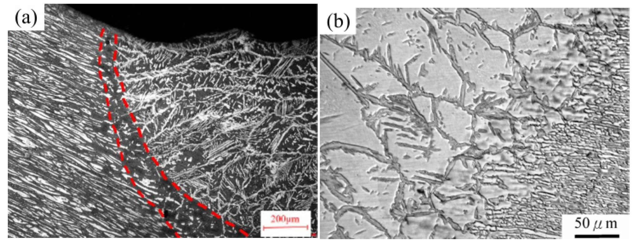
Figure 2.
Sampling diagram for mechanical property testing: (a) uniaxial tensile; (b) microhardness; (c) impact toughness.
Figure 2.
Sampling diagram for mechanical property testing: (a) uniaxial tensile; (b) microhardness; (c) impact toughness.

Figure 3.
Metallographic characterization of DSS2205 PAW welded joints: (a) BM; (b) HAZ; (c) transition region between HAZ and WM; (d) center of WM.
Figure 3.
Metallographic characterization of DSS2205 PAW welded joints: (a) BM; (b) HAZ; (c) transition region between HAZ and WM; (d) center of WM.
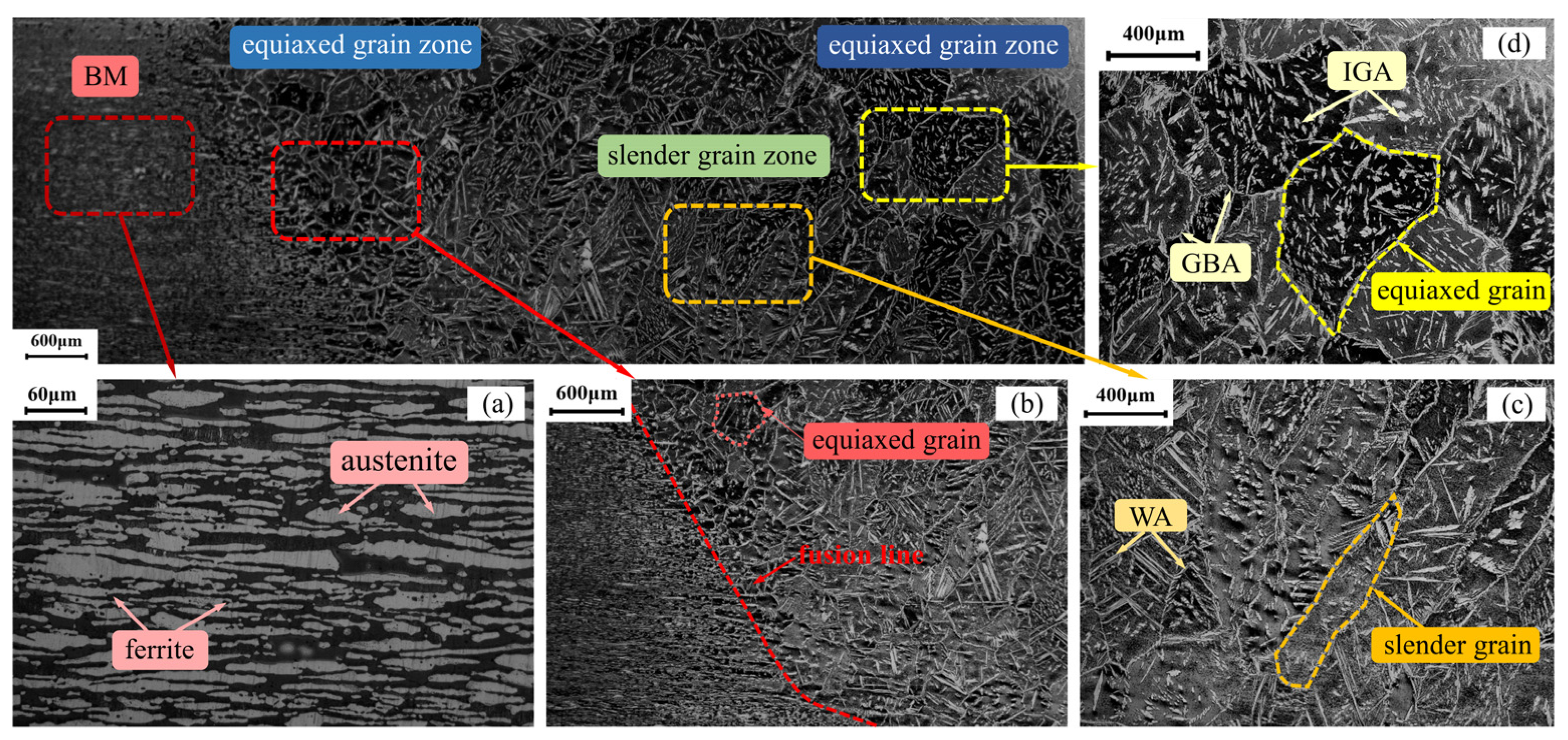
Figure 4.
Phase ratio of DSS2205 PAW welded joints at different characteristic zones.
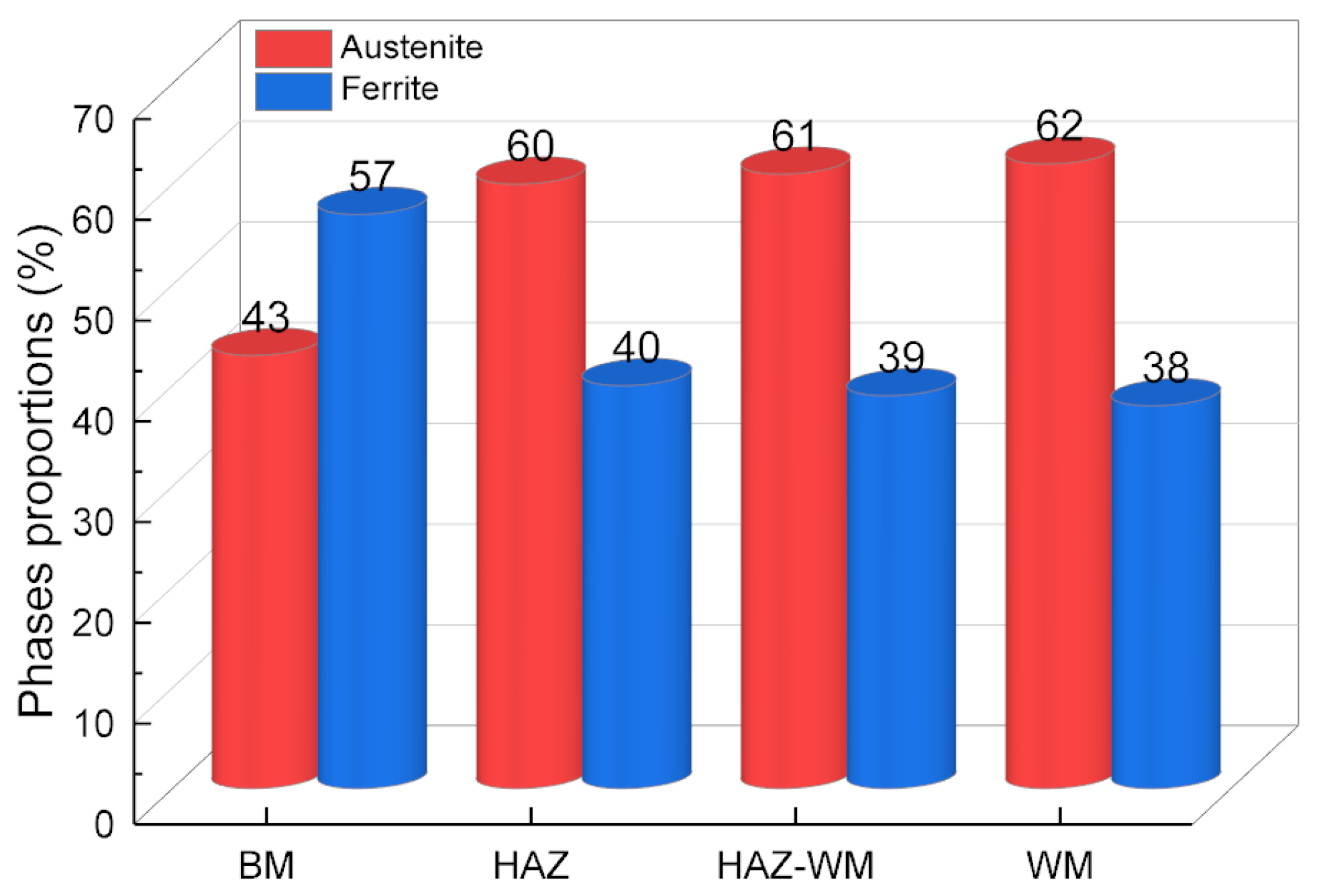
Figure 5.
Results of uniaxial tensile stress–strain experiments.

Figure 6.
Fracture images of tensile test: (a) TWJ; (b) LWJ; (c) LBM; (d) TBM.
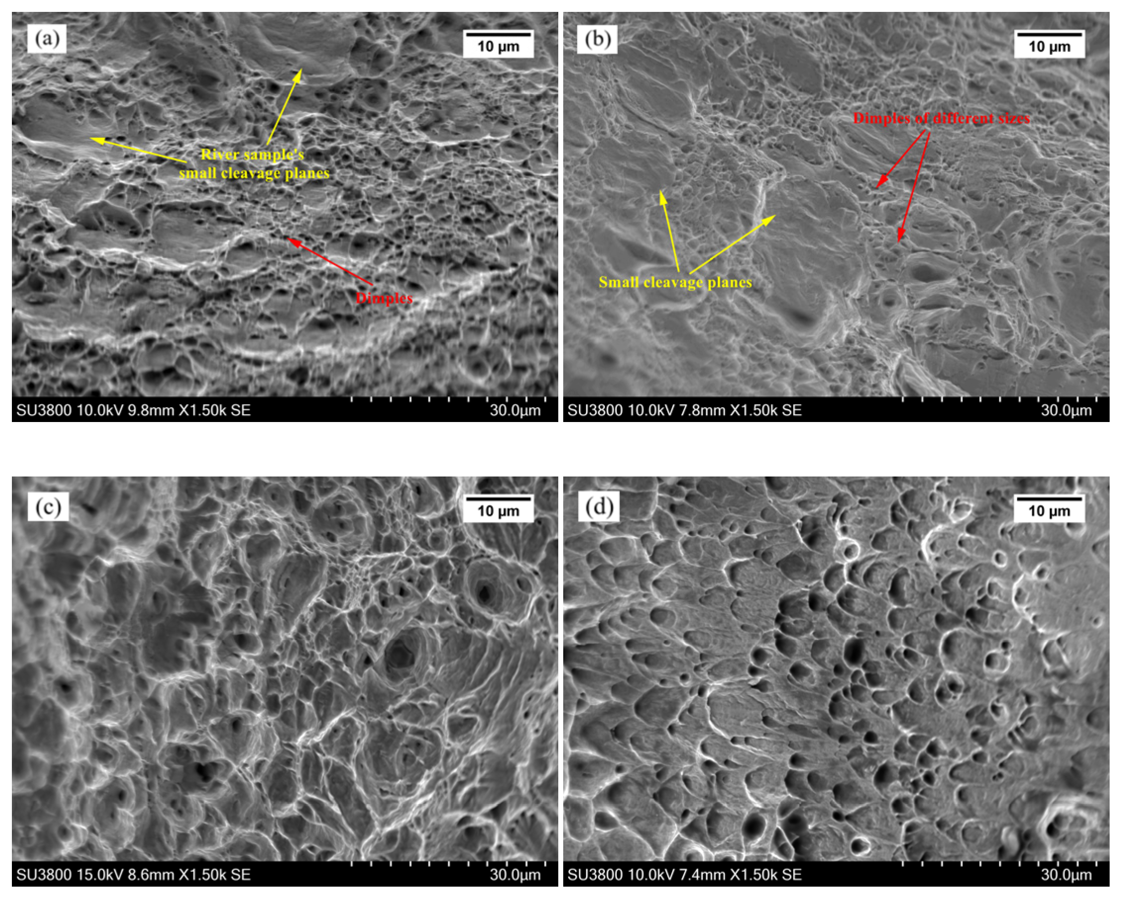
Figure 7.
Distribution of microhardness across whole welded joints.

Figure 8.
Impact energy of weld joints and base material.
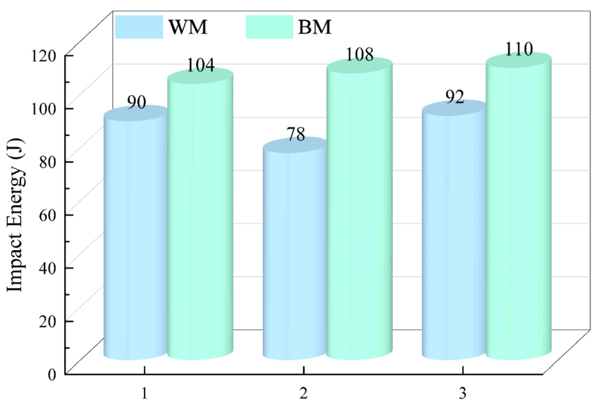
Figure 9.
Fracture images of impact specimens for (a) BM (b) WM.
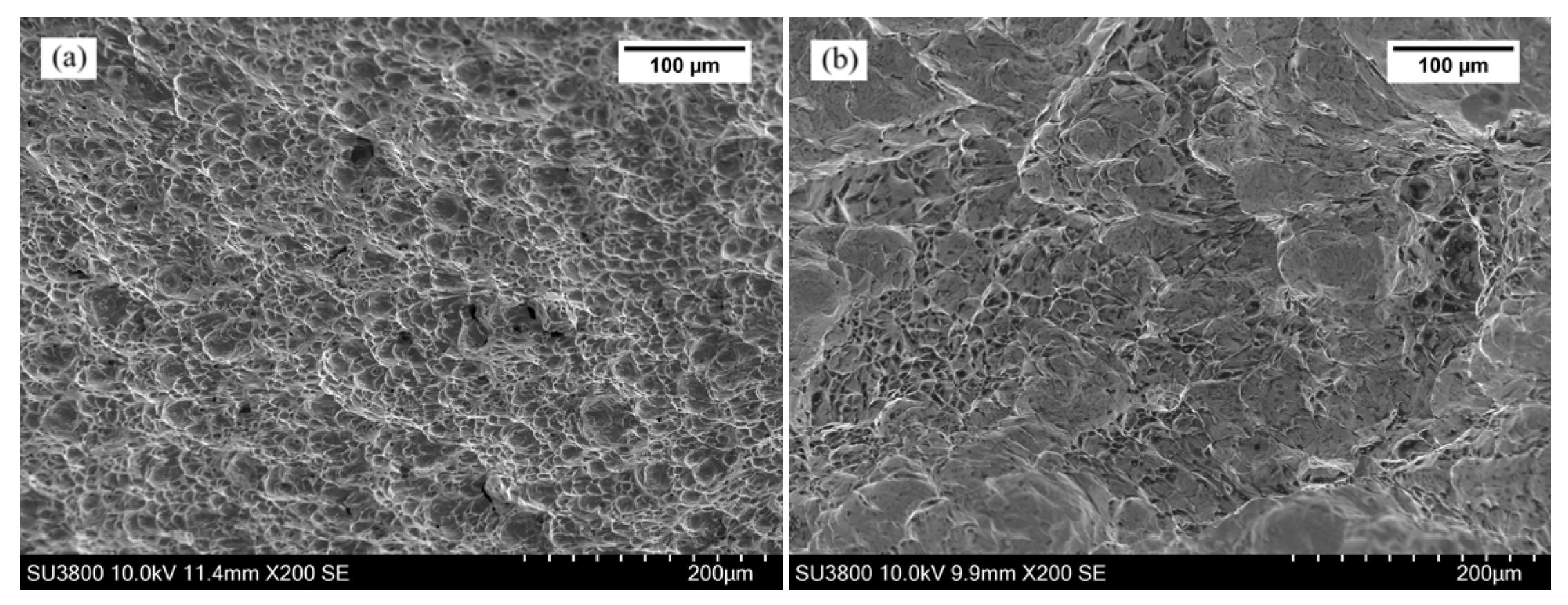
Figure 10.
Typical phase transformation process of DSS during welding.

Figure 11.
Typical thermal cycle curves for different types of welding technologies. Reprinted from Refs. [39,40], with permission from Ref. [39]. Copyright 2016 Physics Procedia.

Table 1.
Chemical composition of base metal and filled metal.
| C | Si | Mn | P | S | Cr | Ni | Mo | N | Fe | |
|---|---|---|---|---|---|---|---|---|---|---|
| SAF2205 | 0.02 | 0.6 | 1.5 | 0.03 | 0.001 | 22.5 | 5.8 | 3.0 | 0.16 | Rest |
| ER2209 | 0.023 | 0.46 | 1.74 | 0.022 | 0.01 | 22.95 | 8.79 | 3.1 | 0.17 | Rest |
Table 2.
Welding process parameters.
| Current (A) | Voltage (V) | Welding Speed (mm/min) | Filler Metal and Protective Gas | Heat Provided (J/mm) |
|---|---|---|---|---|
| 210 | 35.75 | 390 | ER2209 + argon | 3554 |
Disclaimer/Publisher’s Note: The statements, opinions and data contained in all publications are solely those of the individual author(s) and contributor(s) and not of MDPI and/or the editor(s). MDPI and/or the editor(s) disclaim responsibility for any injury to people or property resulting from any ideas, methods, instructions or products referred to in the content. |
© 2024 by the authors. Licensee MDPI, Basel, Switzerland. This article is an open access article distributed under the terms and conditions of the Creative Commons Attribution (CC BY) license (https://creativecommons.org/licenses/by/4.0/).
Share and Cite
MDPI and ACS Style
Hu, X.; Qin, L.; Wang, H.; Zhang, L.; Xie, X. Microstructure Formation and Its Effect on Mechanical Properties for Duplex Stainless Steel 2205 Plasma Arc Welded Joint. Metals 2024, 14, 68. https://doi.org/10.3390/met14010068
AMA Style
Hu X, Qin L, Wang H, Zhang L, Xie X. Microstructure Formation and Its Effect on Mechanical Properties for Duplex Stainless Steel 2205 Plasma Arc Welded Joint. Metals. 2024; 14(1):68. https://doi.org/10.3390/met14010068
Chicago/Turabian StyleHu, Xiaodong, Lu Qin, Huanqing Wang, Lu Zhang, and Xuefang Xie. 2024. "Microstructure Formation and Its Effect on Mechanical Properties for Duplex Stainless Steel 2205 Plasma Arc Welded Joint" Metals 14, no. 1: 68. https://doi.org/10.3390/met14010068
Note that from the first issue of 2016, this journal uses article numbers instead of page numbers. See further details here.