Article

Evaluation of Austenitic Stainless Steel ER308 Coating on H13 Tool Steel by Robotic GMAW Process

by
Jorge Eduardo Hernandez-Flores
1,2,
Bryan Ramiro Rodriguez-Vargas
3,
Giulia Stornelli
3,
Argelia Fabiola Miranda Pérez
4,
Felipe de Jesús García-Vázquez
1,
Josué Gómez-Casas
1 and
Andrea Di Schino
3,*
1
Faculty of Engineering, Universidad Autonoma de Coahuila, Ciudad Universitaria, Arteaga 25350, Mexico
2
Corporacion Mexicana de Investigación en Materiales S.A., Ciencia y Tecnología 790, Saltillo 400, Saltillo 25290, Mexico
3
Dipartimento di Ingegneria, Università degli Studi di Perugia, Via G. Duranti 93, 06125 Perugia, Italy
4
Engineering Department, Mechatronics, Bionics and Aerospace, Universidad Popular Autonoma del Estado de Puebla, 17 Sur, 901, Barrio de Santiago, Puebla 72410, Mexico
*
Author to whom correspondence should be addressed.
Metals 2024, 14(1), 43; https://doi.org/10.3390/met14010043
Submission received: 22 November 2023 / Revised: 19 December 2023 / Accepted: 26 December 2023 / Published: 29 December 2023

Abstract

:
Within the drilling, petrochemical, construction, and related industries, coatings are used to recover components that failed during service or to prevent potential failures. Due to high stresses, such as wear and corrosion, which the materials are subjected to, industries require the application of coating between dissimilar materials, such as carbon steels and stainless steels, through arc welding processes. In this work, an austenitic stainless steel (ER308) coating was applied to an H13 tool steel substrate using the gas metal arc welding (GMAW) robotic process. The heat input during the process was calculated to establish a relationship between the geometry obtained in the coating and its dilution percentage. Furthermore, the evolution of the microstructure of the coating, interface, and substrate was evaluated using XRD and SEM techniques. Notably, the presence of martensite at the interface was observed. The mechanical behavior of the welded assembly was analyzed through Vickers microhardness, and a pin-on-disk wear test was employed to assess its wear resistance. It was found that the dilution percentage is around 18% at high heat input (0.813 kJ/mm) but decreases to about 14% with reduced heat input. Microhardness tests revealed that at the interface, the maximum value is reached at about 625 HV due to the presence of quenched martensite. Moreover, increasing the heat input favors wear resistance.

1. Introduction

The use of coatings as a surface modification technique plays an essential role in the restoration of components that have experienced failures during their time in production and in the prevention of potential future failures. This is particularly crucial in applications where these components are subjected to aggressive conditions, such as mechanical stresses that may weaken the properties of the original material, as well as exposure to corrosive environments [1,2,3,4,5,6,7].
Surface modification techniques exploit filler metals, either in powder form or in solid state, with chemical compositions dependent on the substrate. This enables the adaptation of components to high corrosive environments and high mechanical stresses [8]. An example of this is the use of filler materials with a high nickel content, such as Inconel, to enhance high-temperature resistance [2,9,10]. In applications exposed to aggressive environments where corrosion resistance is critical, stainless steel or high chromium alloy filler materials are employed. Austenitic stainless steels are the most common due to their high corrosion resistance and relatively lower cost compared to other stainless alloys [11,12,13,14].
The use of coatings in dissimilar joints between carbon steels and austenitic stainless steels offers economic benefits in various applications where materials with high corrosion resistance are needed. This approach eliminates the use of expensive all-austenitic stainless steel plates and replaces them with low-cost coated components, resulting in significant cost-effectiveness [15]. However, it is essential to consider several factors, such as the process to use, weldability of the parts, their chemical composition, and the microstructural development that occurs, since this combination of features significantly influences the corrosion resistance and mechanical properties of the resulting joint [16]. Previous research has emphasized the importance of analyzing the interface between the substrate and stainless steel coatings. This is because the thermal gradients generated in the joint, due to the heat input, promote the diffusion and loss of some alloying elements from the weld pool to the substrate, which can affect the material properties and lead to susceptibility to corrosion [17,18].
Various surface modification processes are used, depending on the specific end application. These processes may include welding arc technologies such as gas metal arc welding (GMAW) [19], gas tungsten arc welding (GTAW) [20], cold metal transfer (CMT) [21,22], plasma transferred arc (PTA) [22,23], and high-energy processes such as laser technologies [24,25,26] or additive manufacturing (AM) [27,28].
The GMAW process is one of the most widely used processes in the industrial sector due to its low cost and ease of automation. However, a critical parameter to determine is the metal transfer mode, since it influences the deposition rate of the filler material, the geometry of the weld beads, and consequently, the dilution percentages [17,29].
Spray mode transfer is generally used in high-thickness materials, as it involves continuous fusion of the filler metal and allows for rapid deposition on the substrate using high voltage and current parameters. However, this metal transfer tends to generate a challenging-to-control weld pool, resulting in high dilution and significant heat input [30,31]. In contrast, the short-circuit mode transfer (GMAW-S) relies on an arc that briefly extinguishes, and that is achieved by using lower welding voltages and current, combined with alternating current. This reduces heat input and ensures excellent thermal stability, enabling the production of high-quality coatings, even on thinner substrates [32,33].
The combination of unique features resulting from surface modification through welding processes in dissimilar alloys is of significant interest for tool steel, such as H13 steel, which is used in the manufacturing of extrusion dies, forming applications, forging, and die-casting of aluminum alloys [34,35]. For such types of applications, improving the corrosion and erosion resistance of H13 steel is imperative, as its use in high-temperature processes with aggressive lubricants/coolants leads to rapid degradation of the material [36,37]. In aluminum extrusion dies, the combination of high temperature and the aggressiveness of molten aluminum in terms of corrosion can lead to pitting and the formation of intermetallic layers. This shortens the lifespan of these components, necessitating replacement and sometimes the substitution of H13 steel with more expensive materials [38,39,40,41]. In this context, the main novelty of the research reported in this paper is in defining different material selection strategies. In particular, the use of anticorrosive coatings with alloys exhibiting high corrosion resistance, such as austenitic stainless steels, can be exploited to improve the durability and performance of these components [42].
The present research evaluates the feasibility of the deposition of an ER308 austenitic stainless steel coating on an H13 tool-grade steel substrate through the variation of key operating parameters such as welding current, which allow for evaluation of the influence of heat input on the dilution percentage, microstructural development, hardness, and wear, using the robotic system GMAW-S welding process. We tested a limited number of process parameters, which allowed us to maintain precise control and greater reproducibility across experimental conditions.

2. Materials and Methods

In this work, an H13 tool steel plate with a thickness of 10 mm and ER308 with a high nickel content were used, respectively, as the substrate and filler metal. The initial state of H13 steel is a tempered martensite, following austenitization heat treatment at 1010 °C for 30 min, cooling in air, and tempering at 650 °C for 2 h. The chemical compositions and mechanical properties of these materials are detailed in Table 1 and Table 2.
Bead-on-weld deposits were made on the H13 steel plate using a GMAW robotic process with short-circuit mode transfer. A KUKA KR16-2 robot (Kuka, Augsburg, Germany) was used, connected to a Lincoln POWERWAVE 455 m power source (Lincoln Electric, Cleveland, OH, USA) with an 80%Ar—20%CO2 (10 L/min) mixture as the shielding atmosphere. The H13 steel plate was preheated to 210 °C to prevent residual stresses and reduce the risk of cracks in the heat-affected zone. The process parameters used are displayed in Table 3.

2.1. Heat Input Calculation

The heat input (HI) was calculated based on Equation (1). According to the information provided by the welding process, the efficiency (η) is assumed to be 80%.
H I = V I S η
where HI is the heat input in kJ/mm, V is the welding voltage in V, I is the welding current in A, and S is the welding speed in mm/s.

2.2. Dilution Percent Calculation

The dilution percentage of each coating was calculated using Equation (2) in accordance with Figure 1.
D i l u t i o n ( % ) = A m A c + A m 100
It is important to highlight that this parameter is of interest since it strongly depends on the process parameters and its values tend to demonstrate the union and adhesion of the filler metal on the substrate [43,44]. Generally, in coating or hard banding, dilution plays an outstanding role in the economic part, since values below 10% increase the lack of adhesion integrity, while values above 20% can increase the cost of filler metal [45,46].

2.3. Macro- and Microstructural Characterization

The preparation of both the substrate and the coating was metallographic prepared in accordance with standardized and conventional procedures. To reveal the microstructure of the substrate, a Nital 5% solution was used for 5 s. Visualizing the coating microstructure involved an electrolytic etching process using oxalic acid (10 g C2H2O4 + 100 mL H2O) at 6 V for 60 s.
Macrostructural evaluation was conducted using a Nikon SMZ 745T (Nikon Corp., Tokyo, Japan) stereoscope, and to observe the microstructural development, a Nikon Eclipse MA200 optical microscope and a Tescan MIRA3 (Tescan Analytics, Brno, Czech Republic) scanning electron microscope (SEM) were used. The SEM was equipped with an energy-dispersive X-ray spectroscopy (EDS) detector to perform a semi-quantitative analysis of the chemical composition in different regions of the coating. Additionally, the phases in the coating, interface, and substrate were analyzed using X-ray diffraction Phillips XPert 3040 (Philips, Amsterdam, Netherlands with the following parameters: anode excitation voltage of 45 kV, 30 mA current, scanning angle from 35° to 100° (2θ), scanning speed of 0.02° (2θ)/s, and Cu Kα monochromatic radiation.

2.4. Microhardness

Vickers microhardness evaluation was conducted in accordance with ASTM E384 using a Wilson Hardness Tukon 2500 (Buehler, Lake Bluff, IL, USA) microhardness tester with a 500 gF load. This test was performed both longitudinally and transversely on the coating. In the longitudinal test, microhardness was assessed along all the deposited beads. Meanwhile, the transverse test examined microhardness through the coating, interface, and substrate.

2.5. Pin-on-Disk Test

Dry sliding wear tests were conducted on the substrate and coating using a 100Cr6 pin with a diameter of 6 mm and ~63 HRC (hardness of the pin greater than the hardness of the samples [47]). The test conditions to which the samples were subjected are shown in Table 4.
Subsequently, the width of the wear tracks was measured using SEM and the volume loss was calculated using Equation (3), with reference to standard ASTM G99 [48].
V = π · R · d 3 6 r
where V is the volume loss (mm3), R is the radius of the wear track on the sample (mm), r is the radius of the pin (mm), and d is the average wear track diameter (mm).
Equation (4) was used to calculate the wear rate:
k = V F N · L
where k represents the specific wear rate (mm3/N × m), V is the volume loss (mm3), FN is the applied normal force (N), and L is the sliding distance (m).

3. Results and Discussion

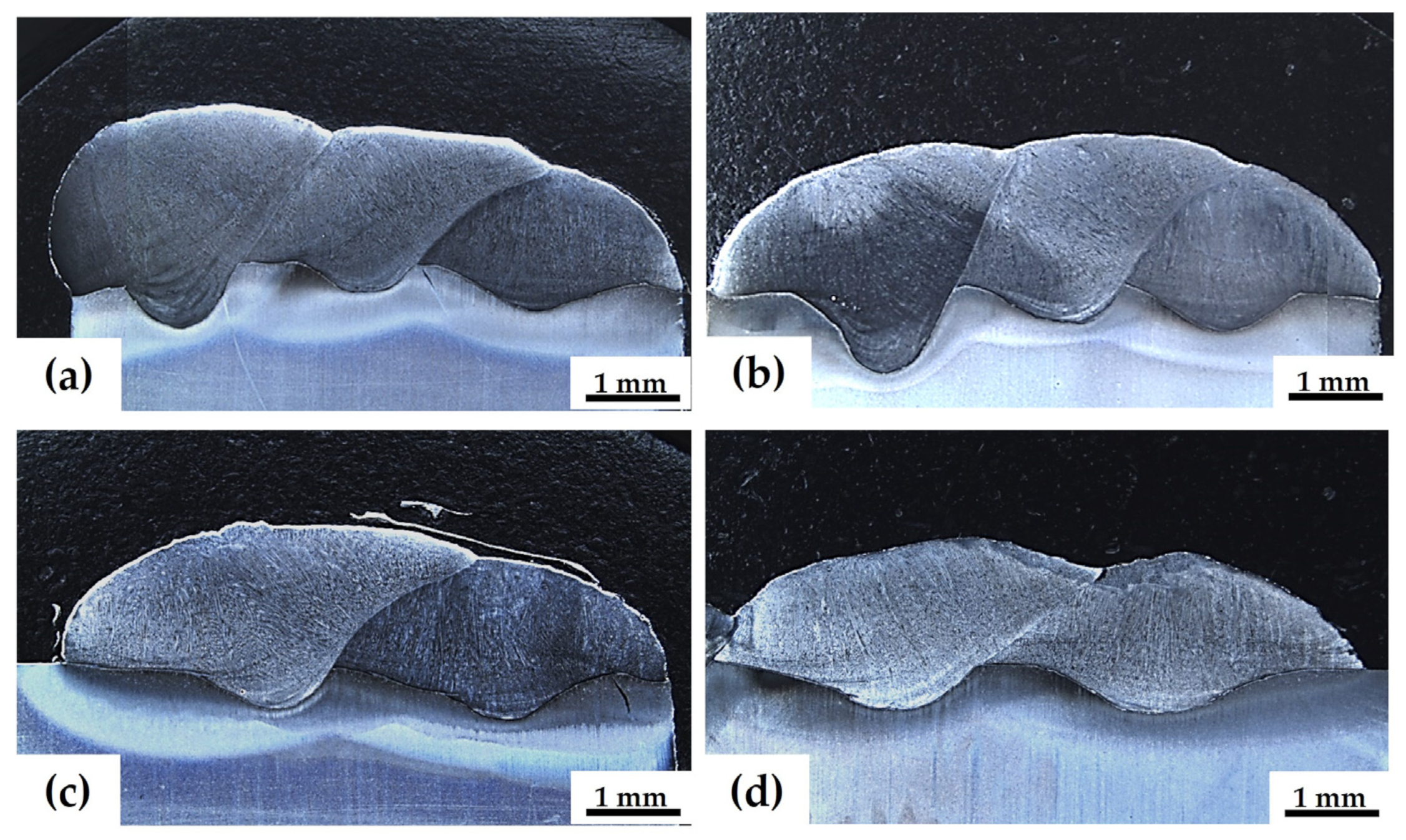
3.1. Macrostructure of Welds and Dilution Percentage

The macrostructural evaluation (Figure 2) confirms the absence of pores and cracks in all samples and demonstrates proper fusion between the coatings and the substrate.
Figure 3a illustrates the relationship between heat input and its influence on the maximum and minimum thickness (Figure 3b) of each coating. It is observed that when heat input reaches a higher value, 0.81 kJ/mm, a significant increase in coating thickness occurs, with a maximum value of 7.49 mm and a minimum value of 4.91 mm. As the heat input decreases, the coating thickness decreases until it reaches a minimum value of 3.83 mm for the heat input of 0.64 kJ/mm. This behavior is related to the higher temperature reached between coating and substrate due to a greater heat input, which promotes substrate melting and a greater coating thickness [49]. Moreover, when significantly more thermal energy is used during the welding process, the resulting cooling rate is slower [50,51,52] and, consequently, the percentage dilution increases (Figure 4), reaching values of 18.3% and 18.1% at 0.81 kJ/mm and 0.79 kJ/mm, respectively. In contrast, at low energy input (0.65 kJ/mm), the dilution percentage decreases to 14.37%. Figure 2a,b shows how a higher heat input allows for non-uniform dilution throughout the coating as the cooling rate increases [53,54]. These results help understand how the process parameters used influence coating thickness and provide a base for effectively tuning these parameters.

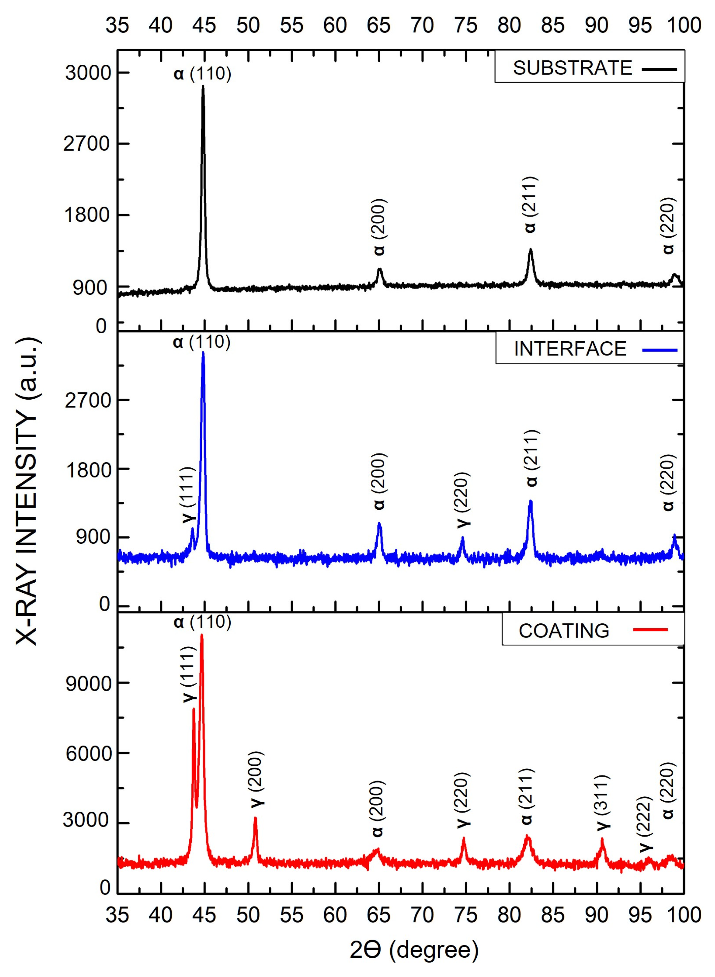
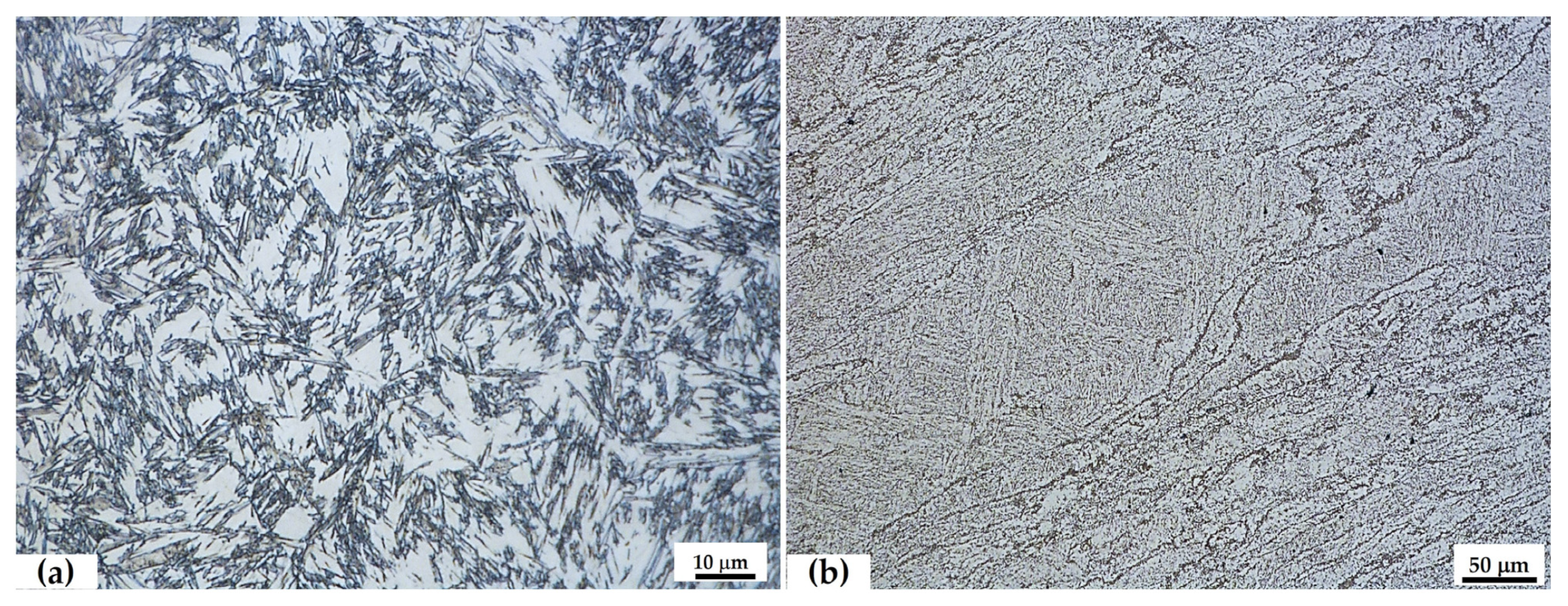
3.2. Microstructure and XRD Measurements

Figure 5 shows the microstructural evolution of each coating, analyzed in different zones (top and middle parts of the coating and the substrate interface). It is observed that, regardless of the heat input, all samples have a similar microstructure. The top zone consists of a large number of columnar dendrites (Figure 5a–d), while towards the middle part of the coating, a columnar growth is evident (Figure 5e–h). This microstructural behavior is attributed to the thermal gradient effect, which influences the cooling rate of each coating. When the filler material is deposited on the substrate, it forms a weld pool, which, as the torch advances, starts various solidification processes. In the internal zone of the weld pool, where the highest temperature is reached, the low cooling rate allows adequate diffusion of chemical elements and favors the columnar austenitic grain formation that grows in the material deposition direction. Instead, at the top of the coating, different solidification processes are observed due to the greater cooling rate reached when the part comes in contact with the atmosphere. This prevents the correct diffusion of chemical elements, thus hindering the formation of austenitic grains and promoting dendritic growth [55,56,57].
Furthermore, as shown by the XRD results for sample C4 (0.64 kJ/mm) in Figure 6, the microstructures reported in Figure 5 result in a solidification mode of the coating in the form of ferrite-austenite, in agreement with Creq and Nieq [46,58]. The XRD analysis reveals, for the various zones (coating, interface, and substrate), the presence of intense peaks at angles of 44° and 84° identified as peaks corresponding to a body-centered cubic (BCC) crystalline structure. Moreover, in the spectra relating to coating and interface, peaks with more intense diffraction angles at 43° and 75° can be observed, identifying the presence of a face-centered cubic (FCC) phase. Therefore, the combination of both ferrite and austenite phases are present in the areas of the coating and at the interface with the substrate. The presence of ferrite in an austenitic steel coating is due to the high cooling rates to which the materials are subjected. The rapid and inhomogeneous solidification prevents δ-ferrite from completely transforming into austenite, causing it to remain a residual ferrite at room temperature [46,59,60].
An important aspect of microstructural analysis is the morphology and quantity of residual ferrite in the coating. At the top of each coating (Figure 5a–d), a lathy ferrite is observed (Figure 7), and as the heat input decreases, the amount of ferrite tends to increase. Previous research has shown that if the cooling rate is slow, the growth of austenite is favored by the diffusion phenomenon, and the predominant residual ferrite presents a vermicular morphology. On the other hand, if the cooling rates are high, diffusion is limited and the formation of lathy ferrite is promoted. Furthermore, it has been demonstrated that the amount of ferrite formed during solidification also depends on the cooling rate, as well as on the heat input, chemical composition, and heat treatment methods. Therefore, with higher cooling rates, and especially in the areas in contact with the ambient temperature, the ferrite content appears to be higher [61,62].
As mentioned above, the interface in all coatings exhibits a similar microstructure. However, for a more detailed analysis, Figure 8a shows the microstructure at the interface for coating C1, highlighting the presence of martensite and austenite. Prior research has found that high Ni and Mo content stabilizes austenite during solidification, leading to the formation of austenite [63]. Martensite formation at the interface zone is attributed to factors such as the cooling rate during solidification of the weld pool [64,65,66]. Additionally, the high number of microalloying elements in the chemical composition of H13 steel and the presence of tempered martensite in the substrate (see Figure 8b) lead to the formation of untempered martensite during the rapid cooling of the welding process [67,68].

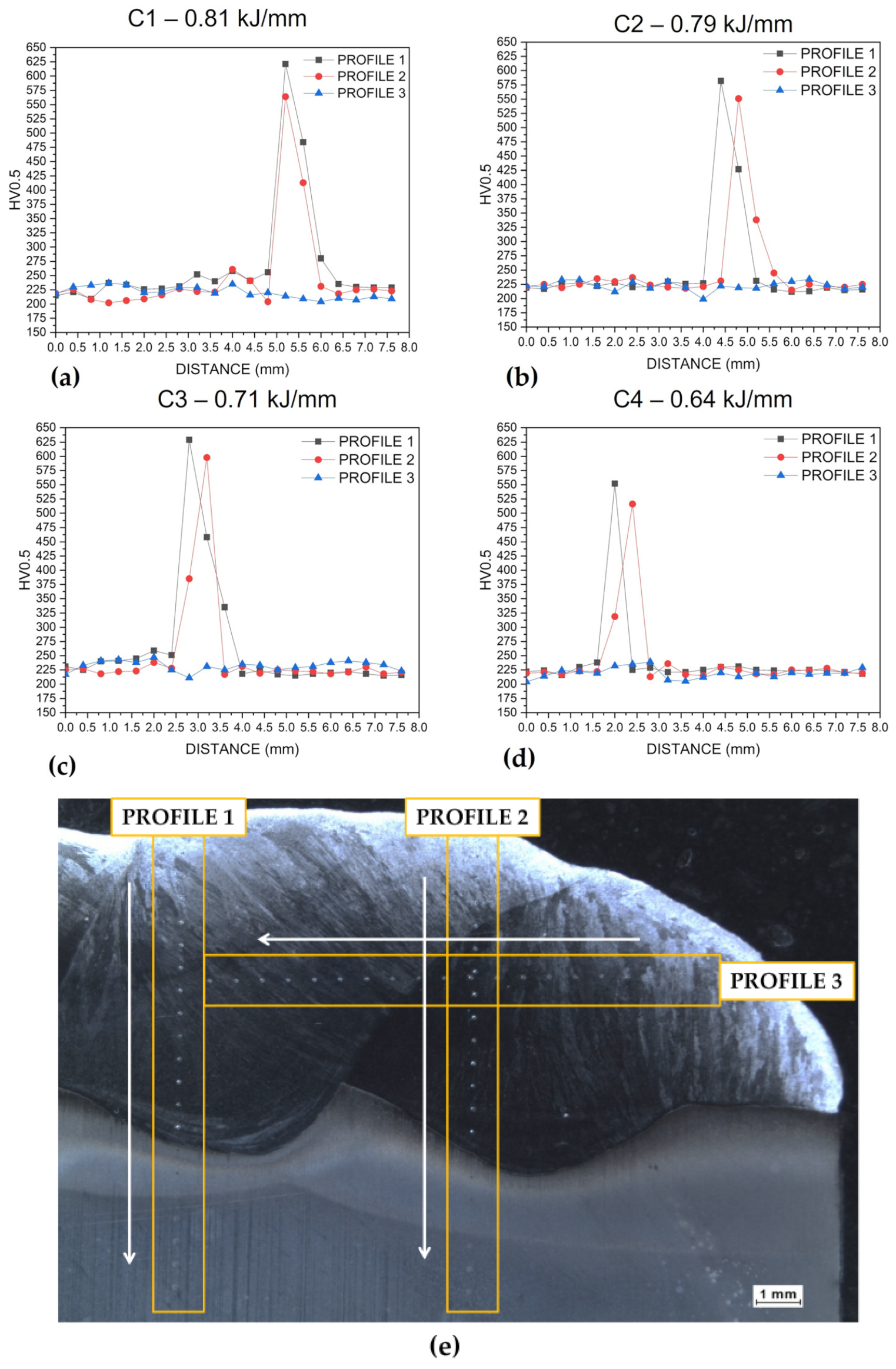
3.3. Microhardness Test
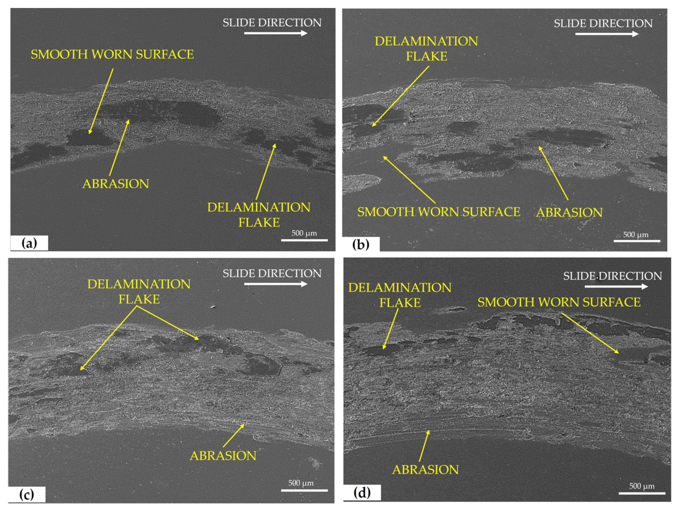
Figure 9 depicts the microhardness profiles of the coatings for different heat input conditions. Two profiles run transversely from the top of the coating to the substrate, and one horizontally across the various weld beads deposited on the substrate (Figure 9e).
The hardness behavior is similar in all samples, despite different heat inputs. The coating and the substrate exhibit hardness values of about 225 HV, while a significantly higher increase to over 600 HV is observed when evaluating the interface and the area of the substrate immediately close to the interface. This behavior is associated with the presence of martensite in these areas, which produces a substantial increase in microhardness, making the interface less ductile [69,70,71].
The results highlight the importance of paying special attention to the interface in applications involving dynamic stresses, as this region can be mechanically vulnerable.

3.4. Wear Test

Figure 10 illustrates the volume loss and wear rate for both the substrate and the coatings. Samples with high heat input (0.81 and 0.79 kJ/mm) exhibit greater wear resistance (with a volume loss of 0.085 and 0.087 mm3, respectively) compared to those with lower thermal input, showing a slight improvement compared to the substrate (0.095 mm3). Likewise, the wear rate remains higher in the low heat input samples, with values of 3.64 and 3.72 mm3/N∙m × 10−3 in coatings C3 (0.71 kJ/mm) and C4 (0.64 kJ/mm), respectively. This suggests that the coatings have a lower mechanical strength when subjected to abrasive wear, and this behavior might be related to the variation in the content of residual austenite and ferrite in the coating and their morphology [72].
Figure 11 shows that the substrate exhibits a friction coefficient of about 0.55, whereas the samples with a heat input of 0.81 kJ/mm and 0.79 kJ/mm have higher friction coefficients of 0.75 and 0.72, respectively. Moreover, these values are also greater than samples with a lower heat input, which have friction coefficients of 0.68 (C3—0.71 kJ/mm) and 0.61 (C4—0.64 kJ/mm). To understand the behavior of the peaks in the friction coefficient graphs, it is crucial to consider the process occurring during tribology testing. When the pin in the tribology test starts to rub against the sample, the static friction coefficient is obtained, represented by the initial peak on the left side of the graph. As the test continues, the dynamic friction coefficient is calculated and the pin starts wearing the sample surface, resulting in the release of particles from the tested material (in this case, the coatings) [73]. These released particles disperse over the wear zone, and due to the temperature generated during the dry pin-on-disk test, these particles can re-adhere to the surface. This leads to what is known as adhesive wear. Once this point is reached, the test exhibits a stable friction behavior, known as the stick–slip effect [74].
The morphology of the worn surfaces was analyzed using SEM and is presented in Figure 12. The images reveal evidence of abrasion wear in all the wear tracks caused by the detachment of oxide particles formed in the coating, which start to slide along the wear track [73,75]. Delamination flakes and a smooth wear surface can also be observed in the samples. Note that a reduced wear track width is evident in the samples with a high heat input, consistent with the volume loss results (see Figure 8).
Chemical analysis using EDS was performed on the wear tracks (Figure 13), evaluating different areas. The results of this chemical analysis indicate the presence of oxygen, chromium, and iron in all samples. The high oxygen content is related to the fact that since the test was conducted under dry conditions, the coating surface heats up and the particles released during the test enter an oxidation state [76,77]. These oxides promote the formation of a protective layer on the surface, reducing friction and wear [78].

4. Conclusions

In this study, coatings of austenitic stainless steel ER308 were applied on an H13 tool-grade steel substrate using the S-GMAW process. Their macro-/microstructural and mechanical evolution was analyzed using various characterization techniques. The main conclusions of the study are as follows:
  • No visible discontinuities such as pores, cracks, or lack of fusion were observed in any of the coatings.
  • The thickness of the coating and its dilution are directly related to the heat input. For a high heat input (0.81 kJ/mm), the dilution percentage and the maximum coating thickness reach higher values (18.3% and 7.46 mm, respectively) compared to the values obtained with lower heat input 0.64 kJ/mm (14.3%—4.34 mm).
  • In all samples, the coating mainly consists of austenite, with lathy ferrite at the top of the coating and columnar austenitic grains in the center. The interface shows the presence of austenite and quenched martensite.
  • Microhardness tests revealed that the coating and the substrate have similar hardness values, which increase significantly at the interface, reaching a maximum of 625 HV due to the presence of martensite in this area.
  • Samples with a higher heat input (0.81, 0.79 kJ/mm) exhibited greater wear resistance.
The conclusions of the present study allow us to define the feasibility of joining dissimilar materials by adequate dilution of the filler material on the substrate. In subsequent work, the corrosion resistance of the welded assembly must be evaluated and analyzed to complete the application of this investigation.

Author Contributions

Conceptualization, J.E.H.-F. and B.R.R.-V.; methodology, J.E.H.-F., F.d.J.G.-V. and J.G.-C.; formal analysis, J.E.H.-F., G.S. and B.R.R.-V.; investigation, J.E.H.-F. and J.G.-C.; writing—original draft preparation, J.E.H.-F.; writing—review and editing, B.R.R.-V., G.S., A.F.M.P. and A.D.S.; supervision, F.d.J.G.-V. and A.D.S. All authors have read and agreed to the published version of the manuscript.

Funding

This research was funded (Scholarship number 21632109-2023) by the National Council of Humanities, Sciences and Technologies (CONAHCYT), Mexico.

Data Availability Statement

The data presented in this study are available on request from the corresponding author. The data are not publicly available due to privacy.

Acknowledgments

The authors thank the engineer Ramiro Rodríguez Rosales for his suggestions and contributions to this research.

Conflicts of Interest

The authors declare no conflict of interest.

References

  1. Chang, S.-H.; Tsai, B.-C.; Huang, K.-T.; Yang, C.-H. Investigation of the Wear and Corrosion Behaviors of CrN Films onto Oxynitriding-Treated AISI H13 Alloy Steel by the Direct Current Magnetron Sputtering Process. Thin Solid Films 2022, 758, 139434. [Google Scholar] [CrossRef]
  2. Kotarska, A.; Poloczek, T.; Janicki, D. Characterization of the Structure, Mechanical Properties and Erosive Resistance of the Laser Cladded Inconel 625-Based Coatings Reinforced by TiC Particles. Materials 2021, 14, 2225. [Google Scholar] [CrossRef] [PubMed]
  3. Gonzalez-Carmona, J.M.; Mambuscay, C.L.; Ortega-Portilla, C.; Hurtado-Macias, A.; Piamba, J.F. TiNbN Hard Coating Deposited at Varied Substrate Temperature by Cathodic Arc: Tribological Performance under Simulated Cutting Conditions. Materials 2023, 16, 4531. [Google Scholar] [CrossRef] [PubMed]
  4. Grossi, E.; Baroni, E.; Aprile, A.; Fortini, A.; Zerbin, M.; Merlin, M. Tribological Behavior of Structural Steel with Different Surface Finishing and Treatments for a Novel Seismic Damper. Coatings 2023, 13, 135. [Google Scholar] [CrossRef]
  5. Di Schino, A.; Porcu, G.; Scoppio, L.; Longobardo, M.; Turconi, G.L. Metallurgical Design and Development of C125 Grade for Mild Sour Service Application. In Proceedings of the NACE CORROSION CONFERENCE SERIES, San Diego, CA, USA, 12–16 March 2006; pp. 061251–0612514. Available online: https://onepetro.org/NACECORR/proceedings-abstract/CORR06/All-CORR06/NACE-06125/118115 (accessed on 19 December 2023).
  6. Di Schino, A.; Valentini, L.; Kenny, J.M.; Gerbig, Y.; Ahmed, I.; Haefke, H. Wear resistance of a high-nitrogen austenitic stainless steel coated with nitrogenated amorphous carbon films. Surf. Coat. Technol. 2002, 161, 224–231. [Google Scholar] [CrossRef]
  7. Stornelli, G.; Gaggiotti, M.; Mancini, S.; Napoli, G.; Rocchi, C.; Tirasso, C.; Di Schino, A. Recrystallization and Grain Growth of AISI 904L Super-Austenitic Stainless Steel: A Multivariate Regression Approach. Metals 2022, 12, 200. [Google Scholar] [CrossRef]
  8. Ranjan, R.; Kumar Das, A. Protection from Corrosion and Wear by Different Weld Cladding Techniques: A Review. Mater. Today Proc. 2022, 57, 1687–1693. [Google Scholar] [CrossRef]
  9. Liu, T.; Chang, M.; Cheng, X.; Zeng, X.; Shao, H.; Liu, F. Characteristics of WC Reinforced Ni-Based Alloy Coatings Prepared by PTA + PMI Method. Surf. Coat. Technol. 2020, 383, 125232. [Google Scholar] [CrossRef]
  10. Magarò, P.; Marino, A.L.; Di Schino, A.; Furgiuele, F.; Maletta, C.; Pileggi, R.; Sgambitterra, E.; Testani, C.; Tului, M. Effect of Process Parameters on the Properties of Stellite-6 Coatings Deposited by Cold Gas Dynamic Spray. Surf. Coat. Technol. 2019, 377, 124934. [Google Scholar] [CrossRef]
  11. Aslam, M.; Sahoo, C.K. Development of Hard and Wear-Resistant SiC-AISI304 Stainless Steel Clad Layer on Low Carbon Steel by GMAW Process. Mater. Today Commun. 2023, 36, 106444. [Google Scholar] [CrossRef]
  12. Kumar, V.; Ranjan Sahu, D.; Mandal, A. Parametric Study and Optimization of GMAW Based AM Process for Multi-Layer Bead Deposition. Mater. Today Proc. 2022, 62, 255–261. [Google Scholar] [CrossRef]
  13. Di Schino, A.; Kenny, J.M.; Barteri, M. High temperature resistance of a high nitrogen and low nickel austenitic stainless steel. J. Mat. Sci. Lett. 2003, 22, 691–693. [Google Scholar] [CrossRef]
  14. Di Schino, A.; Kenny, J.M.; Salvatori, I.; Abbruzzese, G. Modelling primary recrystallization and grain growth in a low nickel austenitic stainless steel. J. Mater. Sci. 2001, 36, 593–601. [Google Scholar] [CrossRef]
  15. Kang, K.; Kawahito, Y.; Gao, M.; Zeng, X. Effects of Laser-Arc Distance on Corrosion Behavior of Single-Pass Hybrid Welded Stainless Clad Steel Plate. Mater. Des. 2017, 123, 80–88. [Google Scholar] [CrossRef]
  16. Li, C.; Qin, G.; Tang, Y.; Zhang, B.; Lin, S.; Geng, P. Microstructures and Mechanical Properties of Stainless Steel Clad Plate Joint with Diverse Filler Metals. J. Mater. Res. Technol. 2020, 9, 2522–2534. [Google Scholar] [CrossRef]
  17. Vlasov, I.V.; Gordienko, A.I.; Eremin, A.V.; Semenchuk, V.M.; Kuznetsova, A.E. Structure and Mechanical Behavior of Heat-Resistant Steel Manufactured by Multilayer Arc Deposition. Metals 2023, 13, 1375. [Google Scholar] [CrossRef]
  18. Valiente Bermejo, M.A.; Eyzop, D.; Hurtig, K.; Karlsson, L. Welding of Large Thickness Super Duplex Stainless Steel: Microstructure and Properties. Metals 2021, 11, 1184. [Google Scholar] [CrossRef]
  19. Singh Singhal, T.; Kumar Jain, J. GMAW Cladding on Metals to Impart Anti-Corrosiveness: Machine, Processes and Materials. Mater. Today Proc. 2020, 26, 2432–2441. [Google Scholar] [CrossRef]
  20. Zhu, L.; Cui, Y.; Cao, J.; Tian, R.; Cai, Y.; Xu, C.; Han, J.; Tian, Y. Effect of TIG Remelting on Microstructure, Corrosion and Wear Resistance of Coating on Surface of 4Cr5MoSiV1 (AISI H13). Surf. Coat. Technol. 2021, 405, 126547. [Google Scholar] [CrossRef]
  21. Tang, X.; Zhang, S.; Cui, X.; Zhang, C.; Liu, Y.; Zhang, J. Tribological and Cavitation Erosion Behaviors of Nickel-Based and Iron-Based Coatings Deposited on AISI 304 Stainless Steel by Cold Metal Transfer. J. Mater. Res. Technol. 2020, 9, 6665–6681. [Google Scholar] [CrossRef]
  22. Rajeev, G.P.; Kamaraj, M.; Bakshi, S.R. Comparison of Microstructure, Dilution and Wear Behavior of Stellite 21 Hardfacing on H13 Steel Using Cold Metal Transfer and Plasma Transferred Arc Welding Processes. Surf. Coat. Technol. 2019, 375, 383–394. [Google Scholar] [CrossRef]
  23. Yuan, Y.; Wu, H.; You, M.; Li, Z.; Zhang, Y. Improving Wear Resistance and Friction Stability of FeNi Matrix Coating by In-Situ Multi-Carbide WC-TiC via PTA Metallurgical Reaction. Surf. Coat. Technol. 2019, 378, 124957. [Google Scholar] [CrossRef]
  24. Morales, C.; Fortini, A.; Soffritti, C.; Merlin, M. Effect of Post-Fabrication Heat Treatments on the Microstructure of WC-12Co Direct Energy Depositions. Coatings 2023, 13, 1459. [Google Scholar] [CrossRef]
  25. Hao, J.; Niu, Q.; Ji, H.; Liu, H. Effect of Ultrasonic Rolling on the Organization and Properties of a High-Speed Laser Cladding IN 718 Superalloy Coating. Crystals 2023, 13, 1214. [Google Scholar] [CrossRef]
  26. Bailey, N.S.; Katinas, C.; Shin, Y.C. Laser Direct Deposition of AISI H13 Tool Steel Powder with Numerical Modeling of Solid Phase Transformation, Hardness, and Residual Stresses. J. Mater. Process. Technol. 2017, 247, 223–233. [Google Scholar] [CrossRef]
  27. Lizzul, L.; Sorgato, M.; Bertolini, R.; Ghiotti, A.; Bruschi, S.; Fabbro, F.; Rech, S. On the Influence of Laser Cladding Parameters and Number of Deposited Layers on As-Built and Machined AISI H13 Tool Steel Multilayered Claddings. CIRP J. Manuf. Sci. Technol. 2021, 35, 361–370. [Google Scholar] [CrossRef]
  28. Le, V.T.; Mai, D.S. Microstructural and Mechanical Characteristics of 308L Stainless Steel Manufactured by Gas Metal Arc Welding-Based Additive Manufacturing. Mater. Lett. 2020, 271, 127791. [Google Scholar] [CrossRef]
  29. Miranda-Pérez, A.F.; Rodríguez-Vargas, B.R.; Calliari, I.; Pezzato, L. Corrosion Resistance of GMAW Duplex Stainless Steels Welds. Materials 2023, 16, 1847. [Google Scholar] [CrossRef]
  30. Stinson, H.; Ward, R.; Quinn, J.; McGarrigle, C. Comparison of Properties and Bead Geometry in MIG and CMT Single Layer Samples for WAAM Applications. Metals 2021, 11, 1530. [Google Scholar] [CrossRef]
  31. Amushahi, M.H.; Ashrafizadeh, F.; Shamanian, M. Characterization of Boride-Rich Hardfacing on Carbon Steel by Arc Spray and GMAW Processes. Surf. Coat. Technol. 2010, 204, 2723–2728. [Google Scholar] [CrossRef]
  32. Chen, T.; Xue, S.; Wang, B.; Zhai, P.; Long, W. Study on Short-Circuiting GMAW Pool Behavior and Microstructure of the Weld with Different Waveform Control Methods. Metals 2019, 9, 1326. [Google Scholar] [CrossRef]
  33. Das, S.; Vora, J.J.; Patel, V.; Li, W.; Andersson, J.; Pimenov, D.Y.; Giasin, K.; Wojciechowski, S. Experimental Investigation on Welding of 2.25 Cr-1.0 Mo Steel with Regulated Metal Deposition and GMAW Technique Incorporating Metal-Cored Wires. J. Mater. Res. Technol. 2021, 15, 1007–1016. [Google Scholar] [CrossRef]
  34. Chhabra, P.; Kaur, M.; Singh, S. High Temperature Tribological Performance of Atmospheric Plasma Sprayed Cr3C2-NiCr Coating on H13 Tool Steel. Mater. Today Proc. 2020, 33, 1518–1530. [Google Scholar] [CrossRef]
  35. Telasang, G.; Dutta Majumdar, J.; Padmanabham, G.; Manna, I. Wear and Corrosion Behavior of Laser Surface Engineered AISI H13 Hot Working Tool Steel. Surf. Coat. Technol. 2015, 261, 69–78. [Google Scholar] [CrossRef]
  36. Hadidi, H.; Saminathan, R.; Zouli, N. Enhancement of Diffusive Oxidation Resistance and Topographical Corrosion Resistance of Hot Work Tool Steels by Nickel Multifunctional Coatings. J. Mater. Res. Technol. 2024, 28, 1227–1232. [Google Scholar] [CrossRef]
  37. Calvo-García, E.; Valverde-Pérez, S.; Riveiro, A.; Álvarez, D.; Román, M.; Magdalena, C.; Badaoui, A.; Moreira, P.; Comesaña, R. An Experimental Analysis of the High-Cycle Fatigue Fracture of H13 Hot Forging Tool Steels. Materials 2022, 15, 7411. [Google Scholar] [CrossRef] [PubMed]
  38. Shinde, T.; Pruncu, C.; Dhokey, N.B.; Parau, A.C.; Vladescu, A. Effect of Deep Cryogenic Treatment on Corrosion Behavior of AISI H13 Die Steel. Materials 2021, 14, 7863. [Google Scholar] [CrossRef] [PubMed]
  39. Xu, G.; Wang, K.; Dong, X.; Yang, L.; Ebrahimi, M.; Jiang, H.; Wang, Q.; Ding, W. Review on Corrosion Resistance of Mild Steels in Liquid Aluminum. J. Mater. Sci. Technol. 2021, 71, 12–22. [Google Scholar] [CrossRef]
  40. Lou, D.C.; Akselsen, O.M.; Onsøien, M.I.; Solberg, J.K.; Berget, J. Surface Modification of Steel and Cast Iron to Improve Corrosion Resistance in Molten Aluminium. Surf. Coat. Technol. 2006, 200, 5282–5288. [Google Scholar] [CrossRef]
  41. Chen, G.; Xue, L.; Wang, J.; Tang, Z.; Li, X.; Dong, H. Investigation of Surface Modifications for Combating the Molten Aluminum Corrosion of AISI H13 Steel. Corros. Sci. 2020, 174, 108836. [Google Scholar] [CrossRef]
  42. Ostolaza, M.; Arrizubieta, J.I.; Lamikiz, A.; Cortina, M. Functionally Graded AISI 316L and AISI H13 Manufactured by L-DED for Die and Mould Applications. Appl. Sci. 2021, 11, 771. [Google Scholar] [CrossRef]
  43. Dass, A.; Moridi, A. State of the Art in Directed Energy Deposition: From Additive Manufacturing to Materials Design. Coatings 2019, 9, 418. [Google Scholar] [CrossRef]
  44. De Oliveira, U.; Ocelík, V.; De Hosson, J.T.M. Analysis of Coaxial Laser Cladding Processing Conditions. Surf. Coat. Technol. 2005, 197, 127–136. [Google Scholar] [CrossRef]
  45. Davis, J.R. Hardfacing, Weld Cladding, and Dissimilar Metal Joining. In Welding, Brazing, and Soldering; ASM International: Tokyo, Japan, 1993; pp. 789–829. [Google Scholar]
  46. Lippold, J.C.; Kotecki, D.J. Welding Metallurgy and Weldability of Stainless Steels; John Wiley & Sons, Inc.: Hoboken, NJ, USA, 2005; ISBN 978-0-471-47379-4. [Google Scholar]
  47. Arsić, D.; Lazić, V.; Mitrović, S.; Džunić, D.; Aleksandrović, S.; Djordjević, M.; Nedeljković, B. Tribological Behavior of Four Types of Filler Metals for Hard Facing under Dry Conditions. Ind. Lubr. Tribol. 2016, 68, 729–736. [Google Scholar] [CrossRef]
  48. ASTM G99; ASTM E384 International Standard Test Method for Wear Testing with a Pin-on-Disk Apparatus G99–17. ASTM International: Conshohocken, PA, USA, 2022.
  49. Luchtenberg, P.; de Campos, P.T.; Soares, P.; Laurindo, C.A.H.; Maranho, O.; Torres, R.D. Effect of Welding Energy on the Corrosion and Tribological Properties of Duplex Stainless Steel Weld Overlay Deposited by GMAW/CMT Process. Surf. Coat. Technol. 2019, 375, 688–693. [Google Scholar] [CrossRef]
  50. Chen, L.; Tan, H.; Wang, Z.; Li, J.; Jiang, Y. Influence of Cooling Rate on Microstructure Evolution and Pitting Corrosion Resistance in the Simulated Heat-Affected Zone of 2304 Duplex Stainless Steels. Corros. Sci. 2012, 58, 168–174. [Google Scholar] [CrossRef]
  51. Rodriguez, B.R.; Miranda, A.; Gonzalez, D.; Praga, R.; Hurtado, E. Maintenance of the Austenite/Ferrite Ratio Balance in GTAW DSS Joints Through Process Parameters Optimization. Materials 2020, 13, 780. [Google Scholar] [CrossRef]
  52. Jiang, Z.; Chen, X.; Yu, K.; Lei, Z.; Chen, Y.; Wu, S.; Li, Z. Improving Fusion Zone Microstructure Inhomogeneity in Dissimilar-Metal Welding by Laser Welding with Oscillation. Mater. Lett. 2019, 2019, 126995. [Google Scholar] [CrossRef]
  53. Bunaziv, I.; Ren, X.; Hagen, A.B.; Hovig, E.W.; Jevremovic, I.; Gulbrandsen-Dahl, S. Laser Beam Remelting of Stainless Steel Plate for Cladding and Comparison with Conventional CMT Process. Int. J. Adv. Manuf. Technol. 2023, 127, 911–934. [Google Scholar] [CrossRef]
  54. Wu, D.; An, Q.; Zhao, G.; Zhang, Y.; Zou, Y. Corrosion Resistance of Stainless Steel Layer Prepared by Twin-Wire Indirect Arc Surfacing Welding. Vacuum 2020, 177, 109348. [Google Scholar] [CrossRef]
  55. Li, S.; Eliniyaz, Z.; Zhang, L.; Sun, F.; Shen, Y.; Shan, A. Microstructural Evolution of Delta Ferrite in SAVE12 Steel under Heat Treatment and Short-Term Creep. Mater. Charact. 2012, 73, 144–152. [Google Scholar] [CrossRef]
  56. Kim, Y.-G.; Lee, D.J.; Byun, J.; Jung, K.H.; Kim, J.; Lee, H.; Taek Shin, Y.; Kim, S.; Lee, H.W. The Effect of Sigma Phases Formation Depending on Cr/Ni Equivalent Ratio in AISI 316L Weldments. Mater. Des. 2011, 32, 330–336. [Google Scholar] [CrossRef]
  57. Fu, J.W.; Yang, Y.S.; Guo, J.J.; Ma, J.C.; Tong, W.H. Microstructure Formation in Rapidly Solidified AISI 304 Stainless Steel Strip. Ironmak. Steelmak. 2009, 36, 230–233. [Google Scholar] [CrossRef]
  58. Lee, D.J.; Byun, J.C.; Sung, J.H.; Lee, H.W. The Dependence of Crack Properties on the Cr/Ni Equivalent Ratio in AISI 304L Austenitic Stainless Steel Weld Metals. Mater. Sci. Eng. A 2009, 513–514, 154–159. [Google Scholar] [CrossRef]
  59. Tate, S.B.; Liu, S. Solidification Behaviour of Laser Welded Type 21Cr–6Ni–9Mn Stainless Steel. Sci. Technol. Weld. Join. 2014, 19, 310–317. [Google Scholar] [CrossRef]
  60. Weidong, H. Microstructure Evolution of 316L Stainless Steel During Laser Rapid Forming. Acta Metall. Sin. 2006, 42, 361–368. Available online: https://www.ams.org.cn/EN/abstract/abstract5556.shtml (accessed on 19 December 2023).
  61. Li, K.; Li, D.; Liu, D.; Pei, G.; Sun, L. Microstructure Evolution and Mechanical Properties of Multiple-Layer Laser Cladding Coating of 308L Stainless Steel. Appl. Surf. Sci. 2015, 340, 143–150. [Google Scholar] [CrossRef]
  62. Li, D.; Lu, S.; Li, D.; Li, Y. Investigation of the microstructure and impact properties of the high nitrogen stainless steel weld. Acta Metall. Sin. 2013, 49, 129. [Google Scholar] [CrossRef]
  63. Zhu, Y.; Chen, J.; Li, X. Numerical Simulation of Thermal Field and Performance Study on H13 Die Steel-Based Wire Arc Additive Manufacturing. Metals 2023, 13, 1484. [Google Scholar] [CrossRef]
  64. Wang, Y.; Sebeck, K.; Tess, M.; Gingrich, E.; Feng, Z.; Haynes, J.A.; Lance, M.J.; Muralidharan, G.; Marchel, R.; Kirste, T.; et al. Interfacial Microstructure and Mechanical Properties of Rotary Inertia Friction Welded Dissimilar 422 Martensitic Stainless Steel to 4140 Low Alloy Steel Joints. Mater. Sci. Eng. A 2023, 885, 145607. [Google Scholar] [CrossRef]
  65. Hamada, A.; Ghosh, S.; Ali, M.; Jaskari, M.; Järvenpää, A. Studying the Strengthening Mechanisms and Mechanical Properties of Dissimilar Laser-Welded Butt Joints of Medium-Mn Stainless Steel and Automotive High-Strength Carbon Steel. Mater. Sci. Eng. A 2022, 856, 143936. [Google Scholar] [CrossRef]
  66. Ansari, R.; Movahedi, M.; Pouranvari, M. Microstructural Features and Mechanical Behavior of Duplex Stainless Steel/Low Carbon Steel Friction Stir Dissimilar Weld. J. Mater. Res. Technol. 2023, 25, 5352–5371. [Google Scholar] [CrossRef]
  67. Kattire, P.; Paul, S.; Singh, R.; Yan, W. Experimental Characterization of Laser Cladding of CPM 9V on H13 Tool Steel for Die Repair Applications. J. Manuf. Process. 2015, 20, 492–499. [Google Scholar] [CrossRef]
  68. Li, S.; Li, J.; Sun, G.; Deng, D. Modeling of Welding Residual Stress in a Dissimilar Metal Butt-Welded Joint between P92 Ferritic Steel and SUS304 Austenitic Stainless Steel. J. Mater. Res. Technol. 2023, 23, 4938–4954. [Google Scholar] [CrossRef]
  69. Guan, H.; Chai, L.; Wang, Y.; Xiang, K.; Wu, L.; Pan, H.; Yang, M.; Teng, C.; Zhang, W. Microstructure and Hardness of NbTiZr and NbTaTiZr Refractory Medium-Entropy Alloy Coatings on Zr Alloy by Laser Cladding. Appl. Surf. Sci. 2021, 549, 149338. [Google Scholar] [CrossRef]
  70. Li, X.; Jiang, P.; Nie, M.; Liu, Z.; Liu, M.; Qiu, Y.; Chen, Z.; Zhang, Z. Enhanced Strength-Ductility Synergy of Laser Additive Manufactured Stainless Steel/Ni-Based Superalloy Dissimilar Materials Characterized by Bionic Mechanical Interlocking Structures. J. Mater. Res. Technol. 2023, 26, 4770–4783. [Google Scholar] [CrossRef]
  71. Wang, X.; Lei, L.; Yu, H. A Review on Microstructural Features and Mechanical Properties of Wheels/Rails Cladded by Laser Cladding. Micromachines 2021, 12, 152. [Google Scholar] [CrossRef] [PubMed]
  72. Di Schino, A.; Testani, C. Corrosion Behavior and Mechanical Properties of AISI 316 Stainless Steel Clad Q235 Plate. Metals 2020, 10, 552. [Google Scholar] [CrossRef]
  73. Zhang, M.; Li, M.; Chi, J.; Wang, S.; Ren, L.; Fang, M. Microstructure and Tribology Properties of In-Situ MC(M:Ti,Nb) Coatings Prepared via PTA Technology. Vacuum 2019, 160, 264–271. [Google Scholar] [CrossRef]
  74. Luiz, V.D.; dos Santos, A.J.; Câmara, M.A.; Rodrigues, P.C.d.M. Influence of Different Contact Conditions on Friction Properties of AISI 430 Steel Sheet with Deep Drawing Quality. Coatings 2023, 13, 771. [Google Scholar] [CrossRef]
  75. Zhao, C.; Xing, X.; Guo, J.; Shi, Z.; Zhou, Y.; Ren, X.; Yang, Q. Microstructure and Wear Resistance of (Nb,Ti)C Carbide Reinforced Fe Matrix Coating with Different Ti Contents and Interfacial Properties of (Nb,Ti)C/α-Fe. Appl. Surf. Sci. 2019, 494, 600–609. [Google Scholar] [CrossRef]
  76. Fox-Rabinovich, G.S.; Gershman, I.S.; Endrino, J.L. Accelerated Tribo-Films Formation in Complex Adaptive Surface-Engineered Systems under the Extreme Tribological Conditions of Ultra-High-Performance Machining. Lubricants 2023, 11, 221. [Google Scholar] [CrossRef]
  77. Morales, C.; Merlin, M.; Fortini, A.; Fortunato, A. Direct Energy Depositions of a 17-4 PH Stainless Steel: Geometrical and Microstructural Characterizations. Coatings 2023, 13, 636. [Google Scholar] [CrossRef]
  78. Ferreira Filho, D.; Souza, D.; Gonçalves Júnior, J.L.; Reis, R.P.; Da Silva Junior, W.M.; Tavares, A.F. Influence of Substrate on the Tribological Behavior of Inconel 625 GMAW Overlays. Coatings 2023, 13, 1454. [Google Scholar] [CrossRef]
Figure 1. Scheme of the cross-section of a coating (dilution percentage measurement).
Metals 14 00043 g001
Figure 2. Macrograph of the coatings obtained with (a) 0.81 kJ/mm, (b) 0.79 kJ/mm, (c) 0.71 kJ/mm, and (d) 0.64 kJ/mm.
Metals 14 00043 g002
Figure 3. (a) Coating thickness as a function of the heat input. (b) Measurement of maximum and minimum coating thickness.
Metals 14 00043 g003
Figure 4. Influence of the heat input on the dilution percentage.
Metals 14 00043 g004
Figure 5. Evolution of microstructure across coating for each set of process parameters: (a) C1—0.81 kJ/mm top zone (columnar dendrites), (b) C2—0.79 kJ/mm top zone (columnar dendrites), (c) C3—0.71 kJ/mm top zone (columnar dendrites), (d) C4—0.64 kJ/mm top zone (columnar dendrites), (e) C1—0.81 kJ/mm middle zone (columnar grains), (f) C2—0.79 kJ/mm middle zone (columnar grains), (g) C3—0.71 kJ/mm middle zone (columnar grains), (h) C4—0.64 kJ/mm middle zone (columnar grains), (i) C1—0.81 kJ/mm interface zone, (j) C2—0.79 kJ/mm interface zone, (k) C3—0.71 kJ/mm interface zone, and (l) C4—0.64 kJ/mm interface zone.
Metals 14 00043 g005
Figure 6. XRD patterns collected from the coating, interface, and substrate of sample C4 (0.64 kJ/mm).
Metals 14 00043 g006
Figure 7. Columnar dendritic microstructure (lathy ferrite) on top of the coating: (a) 0.79 kJ/mm, (b) 0.64 kJ/mm.
Metals 14 00043 g007
Figure 8. Microstructure by OM of (a) the interface of sample C1 (0.81 kJ/mm) and (b) substrate H13.
Metals 14 00043 g008
Figure 9. Vickers microhardness profiles. (a) C1—0.81 kJ/mm; (b) C2—0.79 kJ/mm; (c) C3—0.71 kJ/mm; (d) C4—0.64 kJ/mm; (e) diagram of the direction of microhardness evaluation carried out on each sample.
Metals 14 00043 g009
Figure 10. Tribological results: (a) volume loss; (b) wear rate.
Metals 14 00043 g010
Figure 11. Graph of friction coefficients.
Metals 14 00043 g011
Figure 12. SEM micrographs of the wear tracks. (a) C1—0.81 kJ/mm; (b) C2—0.79 kJ/mm; (c) C3—0.71 kJ/mm; (d) C4—0.64 kJ/mm.
Metals 14 00043 g012
Figure 13. EDS of the wear tracks. (a) C1—0.81 kJ/mm; (b) C2—0.79 kJ/mm; (c) C3—0.71 kJ/mm; (d) C4—0.64 kJ/mm.
Metals 14 00043 g013
Table 1. Chemical composition of substrate and filler metal (wt. %).
MaterialChemical Composition
CCrCuMnMoNiSiVAlFe
H130.454.950.0710.391.260.160.930.470.05Bal.
ER3080.1116.800.140.480.2311.490.590.170.07Bal.
Table 2. Mechanical properties of H13 tool steel and ER308 filler metal.
MaterialMechanical Properties
Hardness
(HRC)
Tensile Strength Ultimate
(MPa)
Tensile Strength Yield
(MPa)
Modulus of Elasticity (GPa)Elongation after Fracture (%)
H1325–2811008202159.0
ER308->600-->30.0
Table 3. Parameters used for coating deposition.
DesignationWelding Parameters
Current
(A)
Voltage
(V)
Welding Speed (mm/s)Wire Feed Speed (mm/s)Heat Input
(kJ/mm)
C1254.320.0550.813
C2252.0 19.80.798
C3229.519.60.719
C4208.319.40.646
Electrode extension: 10 mm
Arc length: 1 mm
Table 4. Parameters used in the pin-on-disk test.
ParametersValue
Normal force3 N
Rotating speed10 cm/s
Test radius4.5 mm
Sliding distance170 m
Sphere radius3 mm
EnvironmentAir
Temperature nominal28 °C
Specimen dimensions1 mm × 1 mm
Disclaimer/Publisher’s Note: The statements, opinions and data contained in all publications are solely those of the individual author(s) and contributor(s) and not of MDPI and/or the editor(s). MDPI and/or the editor(s) disclaim responsibility for any injury to people or property resulting from any ideas, methods, instructions or products referred to in the content.

