
Effect of Residual Stress on the Ultimate Bearing Capacity of Titanium Alloy Pressure Spherical–Cylindrical-Combined Shells
1
School of Naval Architecture and Ocean Engineering, Jiangsu University of Science and Technology, Zhenjiang 212100, China
2
China Ship Scientific Research Center, Wuxi 214082, China
*
Author to whom correspondence should be addressed.
Metals 2024, 14(1), 123; https://doi.org/10.3390/met14010123
Submission received: 11 December 2023
/
Revised: 8 January 2024
/
Accepted: 17 January 2024
/
Published: 20 January 2024
(This article belongs to the Special Issue Mechanical Failure and Metal Degradation of Ships and Marine Structures (Volume II))
Abstract
:Titanium alloy pressure spherical–cylindrical shells enable the effective utilization of the strength of spherical and cylindrical pressure-resistant shell components. In this study, a numerical simulation of the residual stress of a titanium alloy butt-welding plate was conducted by employing sequential coupling and a temperature heat source model. The results of welding residual stress analysis agreed well with the experimental results reported in the literature. Subsequently, the welding residual stress of a titanium alloy pressure spherical–cylindrical shell was calculated and analyzed using the same method. Finally, the influence of residual stress on the ultimate bearing capacity of the shell was assessed. On the inner surface of the shell, the horizontal welding residual tensile stress, perpendicular to the weld path, exhibited a bimodal distribution. The longitudinal welding residual tensile stresses were higher than the horizontal welding residual stress. Near the weld on the outer shell surface, higher longitudinal welding residual tensile stresses existed, whereas the horizontal welding residual stress was compressive. Both the inner and outer shell surfaces exhibited significant longitudinal residual tensile stresses along the weld path, though residual compressive stresses existed on both surfaces. The influence of welding residual stress on the ultimate load-bearing capacity of the shell was minimal.
1. Introduction
Land resources are gradually depleted in the process of long-term human exploitation and consumption, while the ocean area is vast. Human beings have only just started to use an abundant supply of marine resources, which include biological resources, physical energy, chemical resources, and huge reserves of mineral resources such as oil and natural gas hydrates. Currently, the development rate of marine resources is only approximately 5%. The level of development and utilization of marine resources urgently requires improvement.
The development of deep-sea equipment is crucial for the construction of maritime power systems. At present, many submersibles are active in various fields, such as deep-sea exploration and research, seabed oil and gas exploitation, national defense, and so on. The submersibles developed thus far include Alvin from the United States, Nautile from France, Peace I and II from Russia, and Shinkai 6500 from Japan. Their working depth varies from 4500 m to more than 7000 m. In 2012, the Chinese Jiaolong successfully dived 7062 m in the Mariana Trench, reaching the greatest depth of this type of submersible. In contrast to development on land, equipment operating in the deep sea must be able to withstand considerable water pressure to ensure safe operation. Most traditional deep-sea pressure-resistant structures adopt spherical or cylindrical structures, and most research on deep-sea pressure-resistant structures is based on these two types of structures. The titanium alloy pressure spherical–cylindrical composite shell effectively leverages the advantages of spherical and cylindrical pressure-resistant shells and has great potential for application in deep-sea engineering equipment [1]. Titanium alloys boast the advantage of high specific strength and good corrosion resistance. Limited by the current manufacturing technology, titanium alloy pressure spherical–cylindrical-combined shells are generally connected via a welding process, which inevitably produces welding residual stress and deformation. Welding residual stress is a kind of inherent stress that maintains mutual balance inside the object. In the manufacturing and use of components, the plastic deformation caused by uneven thermal expansion and contraction during welding produces residual stress and deformation near the welding area. The existence of welding residual stress adversely affects the integrity and performance of welded components. Especially when combined with external loads, the welding residual stress leads to the premature yield of the structure. Whether this stress affects the ultimate bearing capacity is worthy of research.
Zhao et al. [2,3,4,5,6] studied the welding residual stress of a TC4 titanium alloy plate via numerical simulation, and Chang et al. [7,8,9] conducted numerical simulations and experimental studies on the ultimate strength of thin-walled steel spherical shells with an inner diameter of 1000 mm under the influence of welding residual stress. Zhang et al. [10,11,12,13,14] conducted numerical simulations and experimental studies on the buckling modes of various types of steel annular pressure hulls, such as egg-shaped hulls. Li et al. [15,16,17,18,19,20,21,22] studied the mechanical properties of welded shell structures. Lee et al. [23,24] used experimental methods to study the failure pressure of thin-walled cylindrical shells with an inner diameter of approximately 400 mm under the influence of welding residual stress. Hübner et al. [25,26] conducted finite element numerical simulations on the yield failure behavior of large-scale steel thin-shell structures under the influence of residual stress. Some scholars conducted a finite element method and experimental studies on the ultimate bearing capacities of spherical or cylindrical deep-sea pressure-resistant structures under the influence of residual stress. However, few studies have been conducted on the ultimate bearing capacities of large titanium alloy spherical–cylindrical combined shells under the influence of welding residual stress. Whether welding residual stress affects ultimate bearing capacity on large titanium alloy spherical shells and their degree of influence must be addressed.
Consequently, in this study, the welding residual stress of a titanium alloy pressure spherical–cylindrical combined shell was analyzed using the thermal elastic–plastic finite element and given temperature methods, and the influence of the welding residual stress on the ultimate bearing capacity was investigated. The results provide a basis for the safety and reliability analysis of titanium alloy pressure spherical–cylindrical composite shell structures.
2. Theory and Methods
2.1. Finite Element Analysis of Welding Residual Stress
Welding is a process of local rapid heating and rapid cooling, which has strong instantaneousness. It involves many factors, such as thermal and mechanical metallurgy. With the movement of the welding heat source, the temperature of the welding area changes sharply with time and space. The metallographic structure distribution and physical properties of the materials also change dramatically. Simultaneously, latent heat phenomena occur during material melting and metallographic transformation. Therefore, the non-uniformity and instantaneous characteristics of the welding temperature field are the main causes of residual stress. The main methods currently available for predicting welding stress and deformation are analytical and numerical simulation methods. Among the numerical simulation methods, finite element analysis based on the thermal elastic–plastic theory and the inherent strain method based on elastic theory is the most widely used. In this study, we mainly used the thermal elastic–plastic theory.
Under the action of high temperature, elastic, elastic–plastic, and plastic changes occur in the weldment structure. The thermal elastic–plastic theory combines thermodynamics with structural mechanics, providing a theoretical basis for the welding numerical simulation. Most welding finite element analysis software is also based on this theory.
The calculation of the welding residual stress based on the thermal elastic–plastic finite element method can be performed over the following two steps [27]:
- The sequential coupling analysis is conducted to simulate an instantaneous temperature field change in the welding process.
- A temperature field is introduced into the model as an external load, and the stress and strain of the structure are simulated to obtain the residual stress.
The finite element formula for instantaneous nonlinear heat conduction analysis can be expressed as follows [27]:
where ρ, c, and λ denote the material density, specific heat capacity, and thermal conductivity, respectively; T denotes the instantaneous temperature; denotes the internal heat generation rate; Ts denotes the ambient temperature; qs denotes the heat source; Tα denotes the ambient temperature; α denotes the convection coefficient; and n denotes the normal direction.
In stress field analysis, the following equation exists for a certain element inside the weldment:
where denotes the element stiffness matrix, denotes the incremental force on the unit node, denotes the displacement increment of the node, and denotes the increment of the element’s initial strain equivalent nodal force caused by temperature.
Based on the integrated stiffness matrix (K) and total load vector (dF), the equilibrium equations of this component can be expressed as follows:
where and denotes the displacement increment of each node.
The strain increment in each element is , and the relationship with the element node displacement increment can be expressed as follows:
where B denotes the matrix of the strain vector and node displacement vector in the contact element.
2.2. Nonlinear Ultimate Bearing Capacity of the Structure
The ultimate bearing capacity is determined by considering the structural size, material, and bearing form. With an increase in the load, the structure changes from an elastic state to a plastic state and loses its bearing capacity after reaching its plastic limit. The maximum external load is the ultimate bearing capacity of the structure, considering the material, geometric nonlinearity, and corresponding yield conditions.
- Material nonlinearity: Considering the plastic behavior of the material, the stress–strain relationship of the material changes with increasing stress. When the local yield of the structure occurs, the material enters its plastic state, and the stress–strain relationship no longer remains linear.
- Geometric nonlinearity: The structure undergoes considerable deformation under loading; therefore, the original equilibrium equation derived based on the small-deformation theory is no longer valid. Consequently, a new equation must be established based on the real-time state of the structure after deformation.
To calculate the ultimate bearing capacity of the pressure shell, the first-order buckling mode can be calculated using the initial deflection nonlinear buckling analysis method, multiplied by the initial deflection coefficient, and applied to the finite element model to update the initial geometry. In addition, the arc length method can be used to calculate the nonlinear buckling limit load.
When the arc length method is used to analyze the ultimate bearing capacity, the load is gradually increased, and the stress state of the structure is determined using the von Mises yield criterion to determine whether plastic deformation occurs. The three-dimensional principal stress expression of the von Mises yield criterion can be expressed as follows:
where , , and are the principal stresses in three directions. When the equivalent stress () exceeds the material yield limit, the structure produces plastic deformation, and this structure no longer meets the strength requirements.
The calculation of the ultimate bearing capacity on the pressure hull based on the finite element method mainly includes eigenvalue buckling analysis and nonlinear buckling analysis. First, eigenvalue buckling analysis is performed to obtain the first-order buckling mode. Then, the buckling mode value is multiplied by the initial deflection coefficient and applied to the nonlinear buckling analysis finite element model to simulate the initial geometry of the pressure shell. After inputting the nonlinear parameters of the material, the nonlinear buckling critical load can be obtained [3].
3. Results: Welding Residual Stress
3.1. Verification of Residual Stress of the Titanium Alloy Butt-Welding Plate
3.1.1. Finite Element Model
A titanium alloy butt-welding plate was welded using two plates of dimensions 500 mm × 250 mm × 42 mm. The width of the surface weld was 25 mm, the weld section was a double V-type section, and the dimensions after welding were 500 mm × 500 mm × 42 mm, as shown in Figure 1. A finite element model of the titanium alloy butt-welding plate was developed using the ANSYS2020R2 Workbench finite element software. The accuracy of the welding numerical simulation depends on the reasonable selection of the welding simulation heat source, and the reasonable division of the finite element mesh is also very important. Considering the computational efficiency and accuracy, the titanium alloy butt-welding plate weld and its surrounding mesh were refined, whereas the mesh furthest away from the weld was sparse. The finite element model and mesh grouping are shown in Figure 2.
3.1.2. Material Properties
The filling material of the titanium alloy butt-welding plate weld was the same as the base metal, both of which used Ti80 materials. The yield strength of the section at room temperature was 800 MPa, and the Poisson ratio was 0.3. The relevant material properties are summarized in Table 1 and Figure 3.
3.1.3. Welding Process and Related Parameters
The welding current and voltage of the titanium alloy plate welding were 25 A and 125 V, respectively; the initial welding temperature was set to 25 °C; and the convective heat transfer coefficient was set to 62.5 W/m2·°C. The four corners of the titanium alloy plate were fixed during welding.
3.1.4. Numerical Simulation of Welding Residual Stress
The sequentially coupled thermoelastic–plastic finite element method and the given temperature heat source model [29,30] were used to obtain the welding residual stress of the titanium alloy plate. The surface of the titanium alloy butt-welding plate, perpendicular to the weld center line, was set as Path 1, as depicted in Figure 1. The transverse welding residual stress was set perpendicular to the welding direction.
The transverse welding residual stress distribution of the titanium alloy butt-welded plate is illustrated in Figure 4a, and the transverse welding residual stress on Path 1 is shown in Figure 4b. The transverse welding residual stress of the titanium alloy butt-welding plate exhibits asymmetrical bimodal distribution, and the maximum residual tensile stress is approximately 550 MPa, which is approximately 70% of the yield strength of the material. The transverse residual tensile stress away from the weld decreases sharply.
Figure 4b compares the experimental results of the transverse welding residual stress of the titanium alloy butt-welding plate from [28] with the simulation results obtained in this study, revealing that the simulation results were consistent with the experimental results reported in the literature.
3.2. Welding Residual Stress of Titanium Alloy Pressure Spherical–Cylindrical-Combined Shells
3.2.1. Geometric Model
The inner diameter of the titanium alloy pressure spherical–cylindrical-combined shell model was 4000 mm, the wall thickness was 50 mm, the weld bead at the connection between the spherical head and the cylindrical shell was 10 mm, and the rib spacing was 480 mm. Considering the numerical calculation rate of the ultimate bearing capacity and the symmetry of the model, it was simplified to a quarter-symmetric model, where the lengths of the three ribs were selected for the cylindrical shell, as shown in Figure 5.
3.2.2. Finite Element Model and Boundary Conditions
The finite element model of the titanium alloy pressure spherical–cylindrical-combined shell was developed using ANSYS2020R2 Workbench software, and the finite element mesh was divided and properly densified near the weld. Considering the calculation efficiency of the residual stress, it was divided into 10 layers along the weld thickness direction, as shown in Figure 5b. In the welding analysis, the bottom of the titanium alloy pressure spherical–cylindrical-combined shell alongside nodes 1–3 (Figure 5b) was fully constrained, and a symmetry surface constraint was applied to avoid displacement.
3.2.3. Material Properties
3.2.4. Simulation Results and Analysis of Welding Residual Stress
Using the same calculation method as described in Section 3.1.4, the simulation of the welding residual stress of titanium alloy pressure spherical–cylindrical-combined shells was performed. The inner and outer shells were set perpendicular to the weld direction (axial) as Paths 2 and 3, respectively, and the inner and outer shells along the weld centerline direction (hoop) were set as Paths 4 and 5, respectively, as shown in Figure 5b. The residual stresses perpendicular to the weld direction (axial) and weld centerline direction (hoop) were set as the transverse and longitudinal residual stresses, respectively.
Figure 6 depicts the residual stress distribution of the titanium alloy pressure spherical–cylindrical-combined shell. Figure 7 presents the residual stress perpendicular to the weld on Paths 2 (inner shell) and 3 (outer shell). Figure 8 shows the residual stresses of the inner and outer shells along the welding direction. Figure 9 presents the von Mises residual stress on Paths 2–5.
- A large residual tensile stress existed near the weld on Path 2, and the transverse residual stress exhibited a bimodal distribution. The maximum tensile stress was approximately 170 MPa, which was approximately 20% of the yield strength of the material. The longitudinal residual tensile stress was high, and the maximum value was approximately equal to the yield strength.
- The longitudinal residual stress near the weld on Path 3 had a high tensile stress; the maximum value was approximately 780 MPa, and the transverse residual stress near the weld was compressive stress.
- Along Paths 4 and 5, both the inner and outer shells showed large longitudinal residual tensile stress, whereas the transverse residual tensile stress of the inner shell was small, and that of the outer shell was compressive stress.
- The von Mises residual stress on Paths 2 and 3 perpendicular to the weld direction was larger in the weld part, whereas that on Paths 4 and 5 along the weld direction was larger.
Owing to the characteristics of the ring structure and cooling shrinkage of the circumferential weld during manufacturing, the welding residual stress on the surface of the titanium alloy pressure spherical–cylindrical-combined shell guided the additional bending moment and stress perpendicular to the circumferential weld direction and tensile and compressive stresses existed simultaneously. This phenomenon also appeared in the analysis of the welding residual stress of related structures [32,33].
4. Discussion: Effect of Welding Residual Stress on Ultimate Bearing Capacity
4.1. Ultimate Bearing Capacity of Shells without Considering the Influence of Residual Stress
Errors inevitably occur in actual manufacturing. Therefore, an initial deflection needs to be added to the model. The size of the initial deflection cannot be accurately obtained due to the defects that cause the most unfavorable deformation of the shell. Therefore, a unit load is applied to the model to calculate the first-order buckling mode. The calculated first-order buckling mode is added to the model with a given amplitude as the initial deflection to represent the initial geometric defect and a model with initial defects is generated. Using a titanium alloy pressure spherical–cylindrical-combined shell (Figure 5) as the research object and taking 5% of the shell thickness as the defect amplitude, the arc length method was used to analyze the nonlinear ultimate bearing capacity of the shell without considering the influence of welding residual stress, as shown in Figure 10. The ultimate bearing capacity of the titanium alloy pressure-bonded shell, without considering the influence of the welding residual stress, was approximately 32.9 MPa.
4.2. Ultimate Bearing Capacity of Ttitanium Alloy Pressure Spherical–Cylindrical-Combined Shell Considering Welding Residual Stress
Based on the calculation results of the welding residual stress of the titanium alloy pressure spherical–cylindrical combined composite shell discussed in Section 3.2.4, the sequential coupling analysis method was used to calculate and analyze the nonlinear ultimate bearing capacity of the shell structure with the welding residual stress and residual deformation using the arc length method. Figure 10 presents the load–displacement curve of the titanium alloy pressure spherical–cylindrical-combined shell. The ultimate load was approximately 32.7 MPa, which was not significantly different from the ultimate bearing capacity without considering the influence of welding residual stress. The change range was approximately 0.6%.
5. Conclusions
In this study, we investigated the influence of residual stress on the ultimate strength behavior of a titanium alloy pressure spherical shell. The emphasis was on the numerical simulation of the given temperature method and the arc length method. Considering the initial defects of the structure, the structures with welding residual stress and without welding residual stress were compared and analyzed. According to the finite element method modeling results and analysis shown above, the magnitude and distribution of welding residual stress in the welding seam of a titanium alloy pressure spherical–cylindrical-combined shell after welding were obtained. On this basis, the following conclusions can be drawn regarding the influence of residual stress on the ultimate strength of titanium alloy pressure spherical–cylindrical-combined shells:
- The transverse residual stress on the surface of the inner shell of the titanium alloy pressure spherical–cylindrical combined shell has a bimodal distribution that reaches approximately 20% of the yield strength, and the longitudinal residual tensile stress is higher than the transverse residual tensile stress. The longitudinal residual tensile stress near the weld on the shell surface perpendicular to the weld path is higher, whereas the transverse residual stress is close to the compressive stress.
- The surfaces of the inner and outer shells of titanium alloy pressure spherical–cylindrical-combined shells along the weld direction exhibit a large longitudinal residual tensile stress, and the transverse residual stress of the inner shell is small, whereas the outer shell exhibits residual compressive stress.
- Owing to the characteristics of the ring structure and cooling shrinkage of the girth weld during manufacturing, the additional bending moment and stress perpendicular to the direction of the girth weld are relatively prominent, and tensile and compressive stresses exist simultaneously.
- The welding residual stress has little effect on the ultimate bearing capacity of the titanium alloy pressure spherical–cylindrical composite shell’s structure.
Residual stress is neither the main factor contributing to the decrease in the ultimate strength of the spherical shell nor can it alone reduce the bearing capacity significantly. The maximum decrease found in the ultimate strength was less than 0.6%.
Author Contributions
Conceptualization, Y.W. and L.L.; Data curation, Y.W., B.Z., K.G. and F.L.; Formal analysis, Y.W.; Funding acquisition, L.L. and J.G.; Investigation, L.L.; Methodology, Y.W.; Numerical and experimental study, Y.W.; Resources, J.G.; Software, Y.W.; Supervision, L.L., J.G., B.Z., K.G. and F.L.; Validation, L.L.; Writing—original draft, Y.W.; Writing—review and editing, Y.W., L.L., B.Z., K.G. and F.L. All authors have read and agreed to the published version of the manuscript.
Funding
This work was supported by the National Natural Science Foundation of China (Grant No. 52171312) and the State Key Laboratory of Maritime Technology and Safety (Grant No. QZ2022-Y012).
Data Availability Statement
The data presented in this study are available on request from the corresponding author. The raw/processed data required to reproduce these findings cannot be shared at this time due to technical/time limitations.
Conflicts of Interest
The authors declare no conflict of interest.
References
- Busby, R.F. Manned Submersibles; Office of the Oceanographer of the Navy: Washington, DC, USA, 1976. [Google Scholar]
- Li, G.; Wang, Y.; Liang, Y.; Gao, P.; Liu, X.; Xu, W.; Yang, D. Microstructure and mechanical properties of laser welded Ti-6Al-4V (TC4) titanium alloy joints. Opt. Laser Technol. 2024, 170, 110320. [Google Scholar] [CrossRef]
- Gong, H.; Liu, M.; Zhang, T.; He, Y.; Wu, Y.; Yu, Z. Study on residual stress and optimization of welding parameters in linear friction welding of TC17 titanium alloy. Materials 2022, 15, 8963. [Google Scholar] [CrossRef] [PubMed]
- Kumar, B.; Bag, S.; Amin, M.R. Evaluation of phase Transformation strain and its influence on residual stress generation in laser welded Ti–6Al–4V alloy. J. Manuf. Sci. Eng. 2022, 144, 121002. [Google Scholar] [CrossRef]
- Kumar, B.; Bag, S. Phase transformation effect in distortion and residual stress of thin-sheet laser welded Ti-alloy. Opt. Laser Eng. 2019, 122, 209–224. [Google Scholar] [CrossRef]
- Zhao, X.; Wang, K. Finite element simulation of the residual stress in Ti6Al4V titanium alloy laser welded joint. Int. J. Mater. Res. 2019, 110, 466–475. [Google Scholar] [CrossRef]
- Wei, Y.; Guo, J.; Shen, Y. Analysis of ultimate bearing capacity of pressure spherical shells considering initial deflection, thickness, and residual stress. Ship Mech. 2019, 23, 1331–1338. [Google Scholar]
- Zhang, Z. Study on the Influence of Welding Residual Stress on the Ultimate Bearing Capacity of Pressure-Resistant Structures; China Ship Research Institute: Wuxi, China, 2017. [Google Scholar]
- Yu, C.-L.; Chen, Z.-T.; Chen, C.; Chen, Y.-T. Influence of initial imperfections on ultimate strength of spherical shells. Int. J. Nav. Archit. Ocean Eng. 2017, 9, 473–483. [Google Scholar] [CrossRef]
- Zuo, X.; Zhang, J.; Tang, W.; Li, Y.; Li, H. Buckling behavior of steel and steel–composite cylinders under external pressure. Thin-Walled Struct. 2022, 181, 110011. [Google Scholar] [CrossRef]
- Zuo, X.; Zhang, J.; Tang, W.; Li, Y.; Zhan, M. Collapse of externally pressurized elliptical steel cylinders stiffened with helical composite stripes. Ocean Eng. 2022, 263, 112376. [Google Scholar] [CrossRef]
- Zhang, J.; Cheng, P.; Wang, F.; Tang, W.; Zhao, X. Hydroforming and buckling of an egg-shaped shell based on a petal-shaped preform. Ocean Eng. 2022, 250, 111057. [Google Scholar] [CrossRef]
- Zhang, J.; Dai, M.; Wang, F.; Tang, W.; Zhao, X.; Zhu, Y. Theoretical and experimental study of the free hydroforming of egg-shaped shell. Ships Offshore Struct. 2022, 17, 257–267. [Google Scholar] [CrossRef]
- Zhang, J.; Di, C.; Wang, F.; Tang, W. Buckling of segmented toroids under external pressure. Ocean Eng. 2021, 239, 109921. [Google Scholar] [CrossRef]
- Fazlalipour, N.; Showkati, H.; Ghanbari-Ghazijahani, T. Experiments on welded shells with section alteration under axial and peripheral pressure. J. Constr. Steel Res. 2022, 193, 107277. [Google Scholar] [CrossRef]
- Liu, Y.; Wang, P.; Fang, H.; Ma, N. Characteristics of welding distortion and residual stresses in thin-walled pipes by solid-shell hybrid modelling and experimental verification. J. Manuf. Process. 2021, 69, 532–544. [Google Scholar] [CrossRef]
- Wang, F.; Kong, P.; Sun, Z.; Zhang, J.; Chen, F.; Wu, Y.; Wang, Y. Residual stress properties of the welded thick underwater spherical pressure hull based on finite element analysis. Metals 2022, 12, 1958. [Google Scholar] [CrossRef]
- Dehkordi, Y.G.; Anaraki, A.P.; Shahani, A.R. Investigation of the effective parameters on welding residual stress in GTAW of aluminum cylindrical shell. Indian J. Eng. Mater. Sci. 2020, 27, 77–86. [Google Scholar]
- Kindrats’kyi, B.I.; Nykolyshyn, M.T.; Porokhovs’kyi, Y.V. Influence of residual welding stresses on the limit equilibrium of a transversely isotropic cylindrical shell with internal crack of any configuration. J. Math. Sci. 2019, 243, 101–110. [Google Scholar] [CrossRef]
- Zhou, H.; Shen, C.; Wang, J. Computational analysis of welding radial deformation of typical pressure cylindrical shell with ring stiffener. Int. J. Nav. Archit. Ocean Eng. 2022, 14, 100460. [Google Scholar] [CrossRef]
- Yang, F.; Wen, T.; Wang, Q.; Zhang, L.; Liu, H.; Zhou, Y. Effect of high-frequency induction weld seam on the deformation of M1700 ultra-high strength steel shell structures considering residual tensile stress. Thin-Walled Struct. 2024, 195, 111340. [Google Scholar] [CrossRef]
- Li, L.; Bao, H.; Wan, Z.; Li, Y.; Sun, K.; Luo, G. Influence of residual stress due to the equatorial weld on the ultimate strength of a Ti80 spherical pressure shell. Int. J. Adv. Manuf. Technol. 2021, 116, 1831–1841. [Google Scholar] [CrossRef]
- Lee, C.-H.; Chang, K.-H. Influence of the residual stresses and distortions on the structural behavior of girth-welded cylindrical steel members. Constr. Build. Mater. 2013, 41, 766–776. [Google Scholar] [CrossRef]
- Yu, C.; Chen, Z.; Wang, J.; Yan, S.; Yang, L. Effect of welding residual stress on plastic buckling of axially compressed cylindrical shells with patterned welds. Proc. Inst. Mech. Eng. C 2012, 226, 12. [Google Scholar] [CrossRef]
- Hübner, A.; Teng, J.G.; Saal, H. Buckling behavior of large steel cylinders with patterned welds. Int. J. Press. Vessels Pip. 2006, 83, 13–26. [Google Scholar] [CrossRef]
- Cerik, C.B.; Cho, S.-R. Numerical investigation on the ultimate strength of stiffened cylindrical shells considering residual stresses and shakedown. J. Mar. Sci. Technol. 2013, 18, 11. [Google Scholar] [CrossRef]
- Chen, Z.; Chen, Z.C.; Ajitsheenoi, R.A. Influence of welding sequence on welding deformation and residual stress of a stiffened plate structure. Ocean Eng. 2015, 106, 271–280. [Google Scholar] [CrossRef]
- Li, L.; Zhang, S.; Sun, K.; Wan, Z.; Li, Y.; Sha, Y.; Bao, H. Research on residual stress of equatorial weld of Ti80 pressure spherical shell. Ship Mech. 2021, 25, 946–955. [Google Scholar]
- Liu, C.; Luo, Y.; Yang, M.; Fu, Q. Effects of Material hardening model and lumped-pass method on welding residual stress simulation of J-groove weld in nuclear RPV. Eng. Comp. 2016, 33, 1435–1450. [Google Scholar] [CrossRef]
- Liu, C.; Luo, Y.; Yang, M.; Fu, Q. Three-dimensional finite element simulation of welding residual stress in RPV with two J-groove welds. Weld. World 2017, 61, 151–160. [Google Scholar] [CrossRef]
- Huang, B.; Li, C. Chinese Material Engineering Encyclopedia; Chemical Industry Press: Beijing, China, 2006; Volume 4, pp. 585–596. [Google Scholar]
- Hong, J.B.; Du, Z.M.; Hou, F. Experimental study on welding residual stress of girth weld of large pressure hull. Ship Eng. 2006, 5, 14–18. [Google Scholar] [CrossRef]
- Xu, L.; Huang, X.P.; Wang, F. Effect of welding residual stress on the load-carrying capacity of pressure spherical shells of submersibles. Ship Mech. 2017, 21, 864–872. [Google Scholar]
Figure 1.
Titanium alloy butt-welding plate model and size.
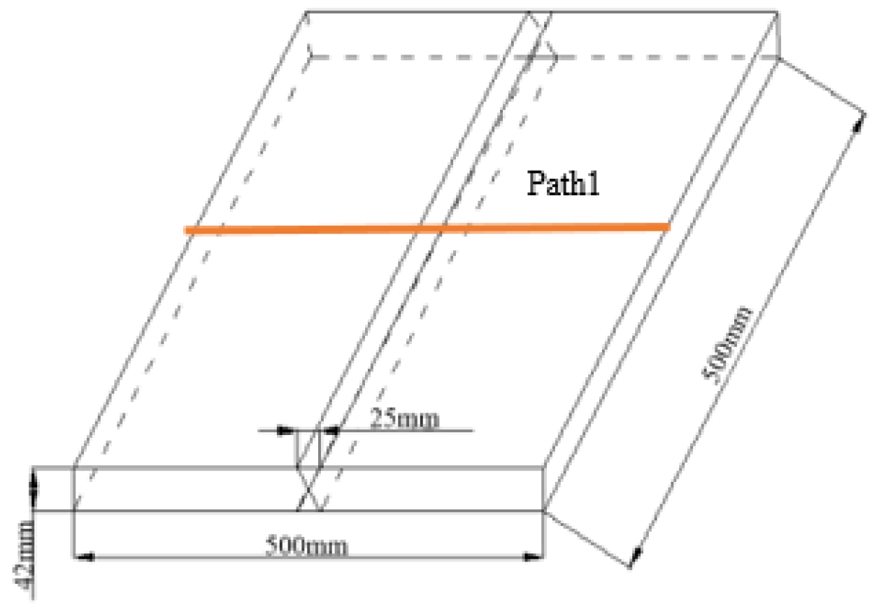
Figure 2.
Finite element meshing of titanium alloy butt-welding plate.

Figure 3.
Stress–strain curves for Ti80 steel under different temperatures.
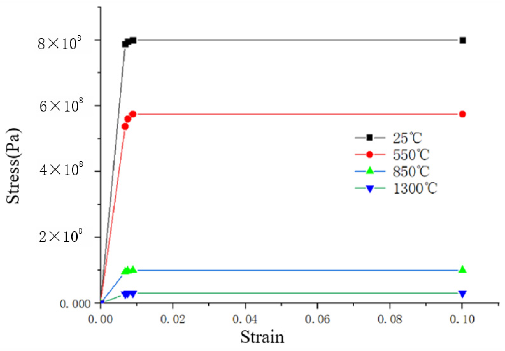
Figure 4.
Welding residual stress calculation results. (a) Transverse residual stress distribution. (b) Comparison of calculated and experimental transverse residual stress values.
Figure 4.
Welding residual stress calculation results. (a) Transverse residual stress distribution. (b) Comparison of calculated and experimental transverse residual stress values.
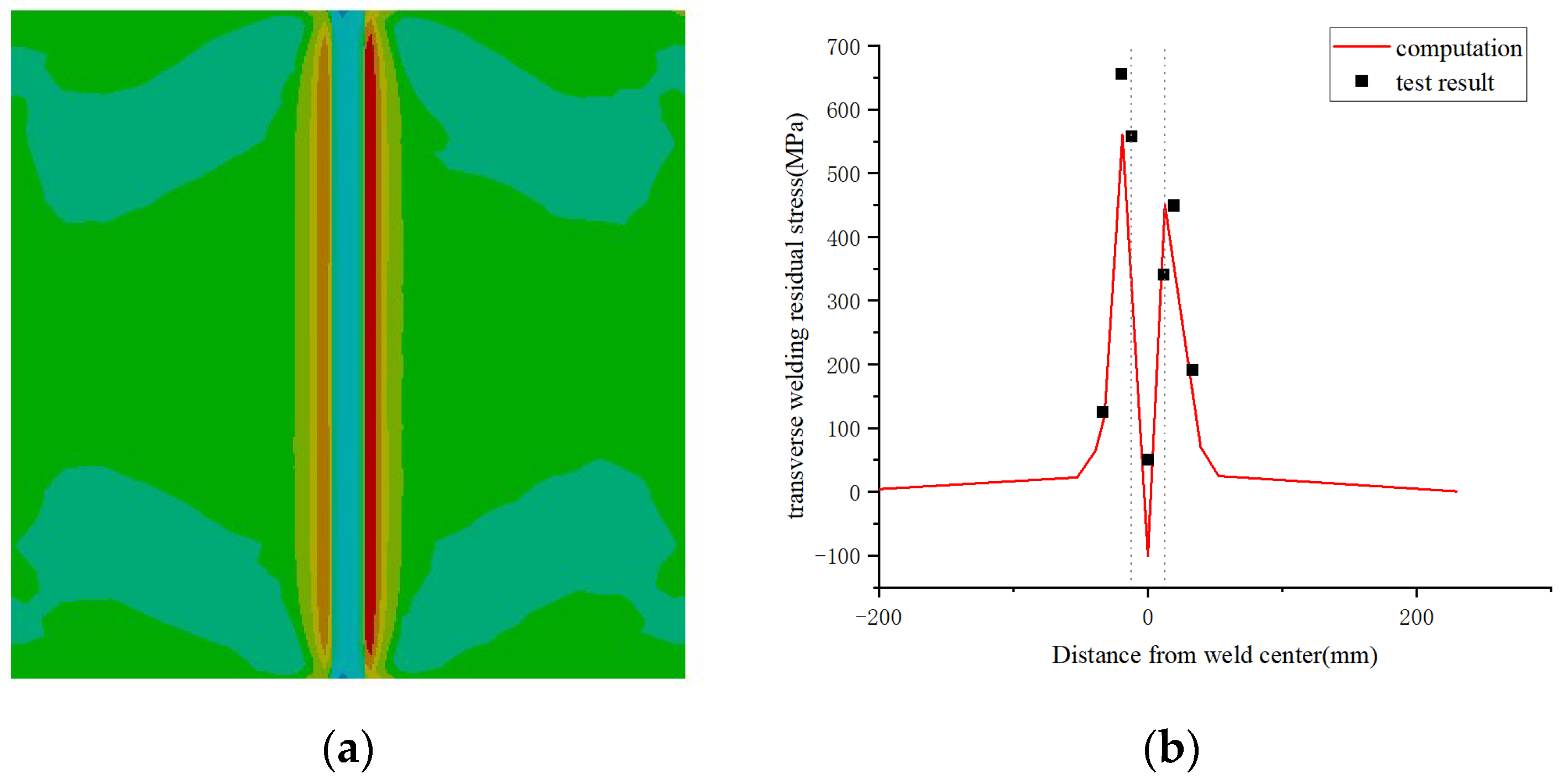
Figure 5.
(a) Geometric model. (b) Finite element model.

Figure 6.
Residual stress distribution of a titanium alloy pressure spherical−cylindrical-combined shell. (a) Transverse stress. (b) Longitudinal stress. (c) von Mises stress.
Figure 6.
Residual stress distribution of a titanium alloy pressure spherical−cylindrical-combined shell. (a) Transverse stress. (b) Longitudinal stress. (c) von Mises stress.
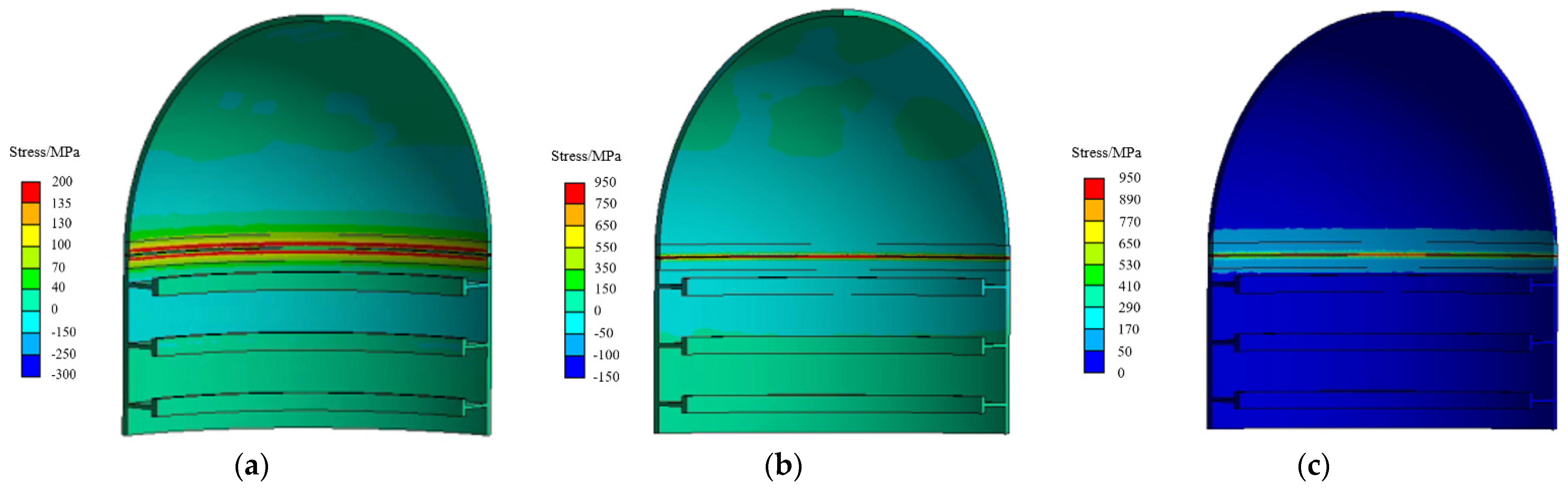
Figure 7.
Residual stress perpendicular to the weld on (a) Path 2 (inner shell) and (b) Path 3 (outer shell).
Figure 7.
Residual stress perpendicular to the weld on (a) Path 2 (inner shell) and (b) Path 3 (outer shell).

Figure 8.
Residual stress of the inner shell and the outer shell along the weld direction.
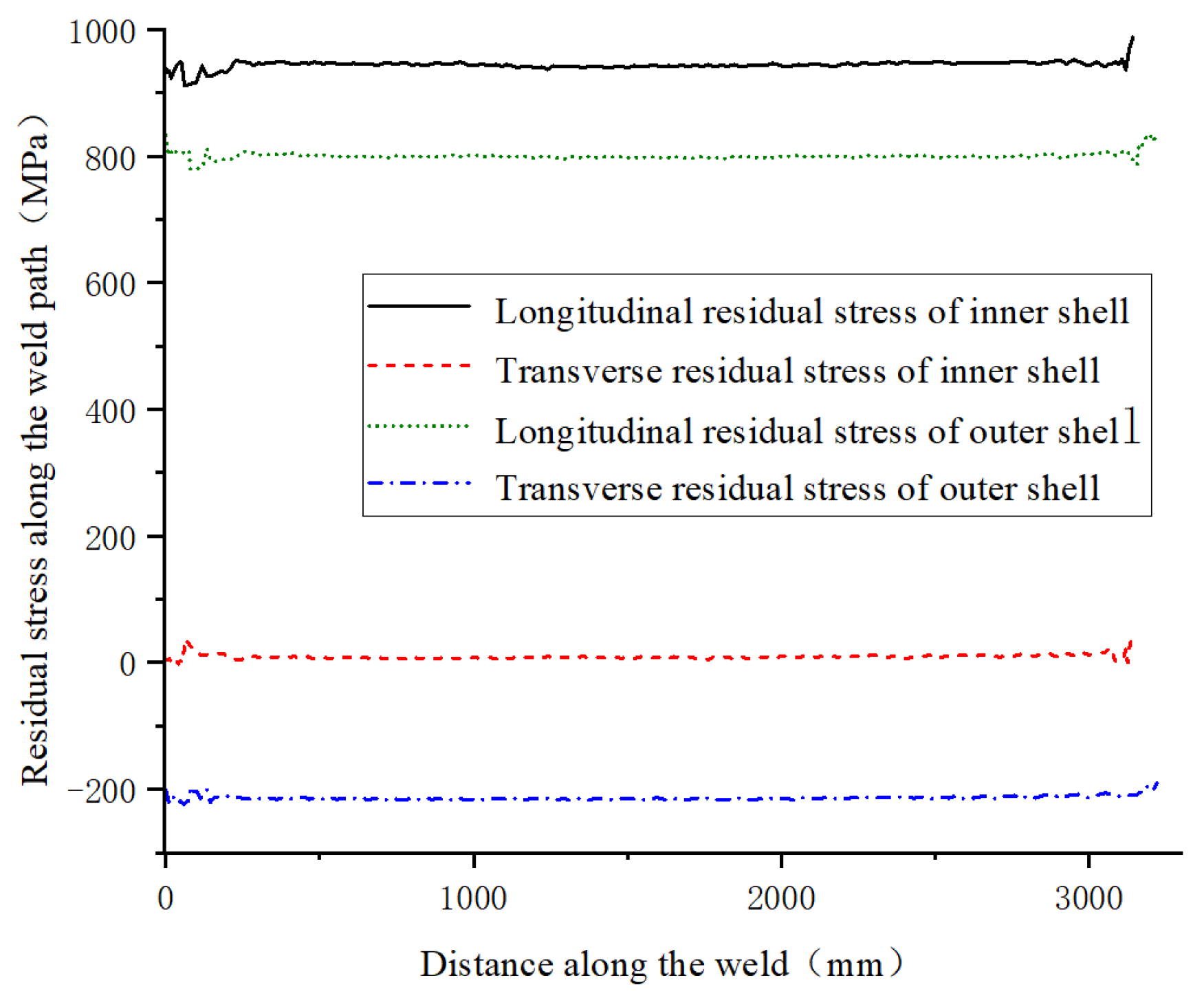
Figure 9.
von Mises residual stress on Paths 2–5.

Figure 10.
Load–displacement curve.


Table 1.
Mechanical properties of Ti80 steel [28].
Table 1.
Mechanical properties of Ti80 steel [28].
| Temperature T (℃) | Elastic Modulus E (MPa) | Poisson Ratio | Thermal Expansion Coefficient K (1/°C) | Heat Transfer Coefficient λ (W/(m·°C)) | Specific Heat C (J/kg·°C) | Density ρ (kg/m3) |
|---|---|---|---|---|---|---|
| 25 | 1.16 × 10⁵ | 0.3 | 1.0 × 10⁻⁵ | 10 | 611 | 4530 |
| 550 | 0.79 × 10⁵ | 0.3 | 0.93 × 10⁻⁵ | 15.8 | 691 | 4530 |
| 850 | 0.14 × 10⁵ | 0.3 | 0.90 × 10⁻⁵ | 22.8 | 730 | 4530 |
| 1300 | 0.04 × 10⁵ | 0.3 | 0.898 × 10⁻⁵ | 26.4 | 775 | 4530 |
Table 2.
Thermal physical performance parameters of TC4 at different temperatures.
| Temperature T (°C) | Elastic Modulus E (MPa) | Poisson Ratio μ | Thermal Expansion Coefficient α (1/°C) | Heat Transfer Coefficient λ (W/(m·°C)) | Specific Heat C (J/kg·°C) | Density ρ (kg/m3) |
|---|---|---|---|---|---|---|
| 20 | 1.14 × 10⁵ | 0.34 | 9.1 × 10⁻⁶ | 6.8 | 611 | 4440 |
| 400 | 8 × 10⁴ | 0.34 | 9.5 × 10⁻⁶ | 10.3 | 691 | 4440 |
| 800 | 3.5 × 10⁴ | 0.34 | 1.04 × 10⁻⁵ | 15.8 | 735 | 4440 |
| 1540 | 1.0 × 10² | 0.34 | 1.1 × 10⁻⁵ | 25.3 | 800 | 4440 |
Table 3.
Stress and strain of TC4 at different temperatures.
| Strain | 0.003 | 0.007 | 0.008 | 0.01 | |
|---|---|---|---|---|---|
| Temperature (°C) | |||||
| 20 | 342 MPa | 798 MPa | 880 MPa | 920 MPa | |
| 400 | 240 MPa | 560 MPa | 560 MPa | 560 MPa | |
| 800 | 105 MPa | 130 MPa | 130 MPa | 130 MPa | |
| 1540 | 6 MPa | 12 MPa | 12 MPa | 12 MPa | |
Disclaimer/Publisher’s Note: The statements, opinions and data contained in all publications are solely those of the individual author(s) and contributor(s) and not of MDPI and/or the editor(s). MDPI and/or the editor(s) disclaim responsibility for any injury to people or property resulting from any ideas, methods, instructions or products referred to in the content. |
© 2024 by the authors. Licensee MDPI, Basel, Switzerland. This article is an open access article distributed under the terms and conditions of the Creative Commons Attribution (CC BY) license (https://creativecommons.org/licenses/by/4.0/).
Share and Cite
MDPI and ACS Style
Wang, Y.; Guo, J.; Zhang, B.; Ge, K.; Li, L.; Lv, F. Effect of Residual Stress on the Ultimate Bearing Capacity of Titanium Alloy Pressure Spherical–Cylindrical-Combined Shells. Metals 2024, 14, 123. https://doi.org/10.3390/met14010123
AMA Style
Wang Y, Guo J, Zhang B, Ge K, Li L, Lv F. Effect of Residual Stress on the Ultimate Bearing Capacity of Titanium Alloy Pressure Spherical–Cylindrical-Combined Shells. Metals. 2024; 14(1):123. https://doi.org/10.3390/met14010123
Chicago/Turabian StyleWang, Yuxuan, Jianting Guo, Bowen Zhang, Keke Ge, Liangbi Li, and Feng Lv. 2024. "Effect of Residual Stress on the Ultimate Bearing Capacity of Titanium Alloy Pressure Spherical–Cylindrical-Combined Shells" Metals 14, no. 1: 123. https://doi.org/10.3390/met14010123
Note that from the first issue of 2016, this journal uses article numbers instead of page numbers. See further details here.