
Improving the Microstructure and Mechanical Properties of Laser-Welded Al–Si-Coated 22MnB5/Galvanized Steel Joints Added by Nickel
School of Material Engineering, Shanghai University of Engineering Science, Shanghai 201620, China
*
Author to whom correspondence should be addressed.
Metals 2023, 13(9), 1600; https://doi.org/10.3390/met13091600
Submission received: 12 July 2023
/
Revised: 15 August 2023
/
Accepted: 30 August 2023
/
Published: 15 September 2023
(This article belongs to the Special Issue Additive Manufacturing Process and Laser Welding of Metals)
Abstract
:To weaken the harm of Al–Si coating and increase the strength of welded joints, variable thicknesses of Ni foil (Ni, an austenitic formation element) were added to the lap laser welding Al–Si-coated 22MnB5 hot stamping steel/galvanized steel joints. The joints’ weld appearance, microstructure, and mechanical properties were explored. The weld altered from an X shape to a Y shape with an increased thickness of Ni foil. During welding, Al–Si coating was melted and diluted into the welding pool, forming δ-ferrite (a rich-Al phase with low toughness and strength) in the fusion zone (FZ) and fusion boundary (FB). This phase deteriorated the strength of the joints. After adding Ni, the amount and size of the δ-ferrite phase decreased. With a significant thickness of Ni foil, δ-ferrite disappeared. However, a new phase (fresh martensite (FM), which formed at low temperature and contained rich Ni) probably formed, except PM (previous martensite (PM), which formed at high temperature and contained little Ni or no Ni). The heat-affected zone (HAZ) on the side of 22MnB5 comprised a coarse martensite zone, refined martensite zone, martensite + ferrite zone, and tempered martensite zone from the FZ to the basic material. HAZ on the side of galvanized steel mainly contained ferrite and pearlite. After adding the Ni foil, the strength of the joint was greater than that without Ni. The maximum strength of the joint can be up to 679 MPa because of the disappearance of δ-ferrite. Meanwhile, the toughness of the joint increased. The fracture mode was from three mixed fractures (cleavage, quasi-cleavage, and dimple) to one fracture (dimple).
1. Introduction
The increasing popularity of automotive lightweight design concepts has greatly promoted the application and extensively of ultra-high-strength steels (UHSS) [1,2,3]. 22MnB5 steel is an ordinary steel with an ultimate tensile strength of 1.5 GPa after hot stamping. During the hot stamping process, 22MnB5 steel is heated to 900~950 °C, held for 5–10 min, and then stamped and quenched in a closed and water-cooled mold to obtain full-martensite [4]. However, there are some problems in the hot stamping process, such as oxidation and decarburization on the surface of the steel. Coating is a highly effective method of protecting steel. Al–Si coating is a robust barrier, often utilized to solve problems, having a thickness of 20–40 μm [5,6].
In the extensive application of Al–Si-coated 22MnB5 hot stamping steel, it is possible to meet some problems of joining 22MnB5 to conventional steel (such as galvanized steel). Galvanized steel has high corrosion resistance and is also widely used in the automotive industry [7]. Strangely, the serious problem is the new phase formed in the fusion zone (FZ) or fusion boundary (FB), which decreases the mechanical properties of the welded joint during the lasing welding of Al–Si-coated 22MnB5 by itself or dissimilar steels between Al–Si-coated 22MnB5 and conventional steel [8,9]. The reason is that Al–Si coating melts and enters the molten pool during the welding process. In the following cooling process, Al is aggregated in the FZ or FB; accordingly, the Al-rich phase forms in the FZ or FB. The crack often originates and extends from this phase [10,11,12].
For the study of the aluminum-rich phase, different researchers had different results. Kim et al. [13] considered the aluminum-rich phase a Fe–Al-brittle intermetallic compound (IMC), which weakened the strength of the joint. However, other researchers revised this result. Because Al was up to 12 wt.% in the Fe–Al binary phase diagram, Fe–Al intermetallic compounds are probably produced. Therefore, the opinion was that the aluminum-rich phase was δ-ferrite. Al is a ferrite-stabilizing element. Al–Si coating dilutes in the welding pool and aggregates, which promotes a high-temperature phase forming. Lin et al. [14] considered that the Al-rich phase was not an Fe–Al intermetallic compound. Saha et al. [15] also confirmed that the phase was δ-ferrite in the phase diagram. The hardness of the Al-rich phase was very low; it was a soft phase.
Based on the above, the traditional method was to remove the Al–Si coating before welding, such as laser cleaning and sandpaper grinding. However, the additional work would consume time and increase the cost. Therefore, in situ ablation methods were used and studied in laser welding Al–Si-coated hot stamping steel. Lin et al. [16] provided laser-filler welding (a low-carbon steel filler metal added). Through the dilution effect of filler wire and the enhancement of the flow of the molten pool, the content and distribution of δ-ferrite decreased, which improved the mechanical properties of the welded joint. VÖLKERS et al. [17] applied ultrasonic-coupled laser welding to inhibit the Al segregation in the fusion zone. Khan et al. [18] depressed the formation of δ-ferrite by coating colloidal graphite onto the surface of 22MnB5 steel to reduce the concentration of δ-ferrite.
In order to meet practical applications, it may be necessary to laser weld Al–Si-coated 22MnB5 hot-formed steel with low-carbon steel (galvanized steel), which can reduce costs and meet market demand. However, during laser welding, the Al–Si coating will enter the molten pool and cause the segregation of Al elements, which will lead to the formation of δ-ferrite. In order to eliminate the negative influence of the Al–Si coating, the above-mentioned method of removing the coating (laser cleaning) can be used, in addition to adding austenitic elements (such as Ni). Compared with the method of removing the coating, the method of adding austenitic elements (Ni) has more advantages (cost savings, high efficiency). Therefore, in this study, an austenite-stabilizing element, Ni, was added to the alloy of the molten pool. Variable thicknesses of Ni foil were added between the two base materials. The microstructure and mechanical properties of welded joints under different Ni foil thicknesses were studied.
2. Experimental Materials and Procedures
In this study, the experimental materials were 1.4 mm thick Al–Si-coated 22MnB5 hot-stamping steel and 2 mm thick DC51D hot-dip galvanized steel. The microstructure of the base materials is shown in Figure 1. The microstructure of 22MnB5 steel was martensite, and the microstructure of galvanized steel (GA) was ferrite (F) and a small amount of pearlite (P). The chemical composition and tensile properties of the two base materials are shown in Table 1. The ultimate tensile strength (UTS) and yield strength (YS) of 22MnB5 steel were 1500 MPa and 1200 Mpa, respectively. Galvanized steel (GA) had an ultimate tensile strength (UTS) and yield strength (YS) of 350 Mpa and 300 Mpa, respectively, and an elongation of 11.5%.
The Al-Si coating thickness of 22MnB5 steel is about 30 μm, and the coating thickness of galvanized steel is about 10 μm. The Al-Si coating consists of α-Fe (Al, Si), Fe2 (Al, Si)5, and Fe (Al, Si), named I, II, and III zones in Figure 2a, same as references [19,20]. The GA coating is primarily composed of two regions. Region IV was Fe3Zn10 (Γ), Fe5Zn21 (Γ1), and region V was FeZn10 (δ) and FeZn13 (ζ), as shown in Figure 2b, same as references [21,22]. All sheets are machined into 100 mm × 80 mm sizes via wire EDM.
IPG YLS-5000 ytterbium fiber laser (Cruise, Germany) was adopted to weld with a lap joint. KUKA six-axis linkage robot (Cruise, Germany) was used for experimental automation. The laser wavelength was 1060–1080 nm, the minimum focusing spot size was 0.4 mm, the beam focal length was 310 mm, and the maximum laser power was 6 kw. 22MnB5 steel was on the top, and galvanized steel was on the bottom. The laser beam is irradiated vertically on the top surface of 22MnB5 steel. The welding speed and laser power are fixed at 2 m/min and 3 kw. A variable thickness of Ni foil was put between the 22MnB5 steel and galvanized steel. Figure 3 is a schematic diagram of welding.
Specimens were cut vertically to the weld for microstructure analysis and strength testing. The dimensions of the tensile shear test specimen are shown in Figure 4. The tensile shear experiments were carried out at room temperature at a 2 mm/min rate to acquire strength parameters. More than three specimens were used for experiments to obtain an average, and the error of each set of data is within the allowable range. In order to observe the microstructure, the specimen for microstructure analysis was polished with coarse and fine sandpaper at first, then polished with a polishing machine (Buehler, Lake Bluff, IL, USA), and finally etched with 4% initial solution. The microstructure of the welded joints was analyzed using optical microscope (OM, Keyence Corporation, Shanghai, China) and scanning electron microscope (SEM, S-3400N, Tokyo, Japan) with an energy dispersive spectrometer (EDS, S-3400N, Tokyo, Japan). The fracture surface was also analyzed using them. The microhardness was tested using Micro Vickers (Agilent, Beijing, China) at a 100 g load for 10 s.
3. Results and Discussion
3.1. Weld Appearance
With the addition of Ni foil of different thicknesses, the weld profiles of the welded joints are shown in Table 2. The weld shape was X-shape without Ni foil (No. 1), while the weld shape changed into Y-shape with Ni foil (No. 2 and 3). After measuring the widths of the welded joints, the top width (B1) had little change. The cross-section width (B2) decreased slightly, and the bottom width (B3) showed a decreasing trend, as shown in Table 2.
The shape and size of the weld are mainly affected by the value of the heat input. When Ni foil was not added, the heat input was large enough, and the depth of the key hole was large. A strong vortex occurred on the upper and lower surfaces of the weld to obtain a completely penetrating weld. Both the top width (B1) and the bottom bead width (B3) were wide, so the weld shape is an X-shape. After adding Ni foil at the same heat input, Ni foil would absorb some energy, which led to a decrease in heat at the bottom of the weld. Therefore, the weld is Y-shaped (No. 2 and No. 3).
3.2. Microstructure
After laser welding dissimilar steels, the welded joint can be divided into a fusion zone (FZ), heat-affected zone (HAZ), and base material (BM). Figure 5 gives the optical images in FZ with 0, 30, and 100 μm Ni foil. Without Ni foil, FZ and FB (fusion boundary) comprised a lath-like structure and strip-like white phase (Figure 5b,c). After adding a little Ni foil (30 μm), the amount and size of the white phase obviously decreased. At the same time, a new grey phase (FM) appeared. However, no white phases were observed with more thickness of Ni foil (100 μm).
To thoroughly analyze the microstructure of the FZ, the SEM and EDS analytical results are given in Figure 6 and Table 3. The color of the “white phase” in Figure 5 changed to black color. This was because these phases contained lightweight elements (Al). From the EDS results, P1,P2, P3, and P4 all contained some Al (7.65%, 6.73%, 3.76%, and 3.11%). The same as reference [23], the Al element belonged to the ferrite-forming element and promoted the formation of δ-ferrite (white band-like). During the laser welding, Al-Si coating was melted into FZ, and the gathering of Al in FZ, especially in FB, δ-ferrite phases were formed. However, Zn did not exist in FZ. This was because the boiling point of Zn was very low (903 °C). Nearly all of them were vaporized during the welding process. Therefore, little or no Zn existed in FZ after welding.
Except for the “black phases”, other phases expressed lath-like. Based on the composition of the base material and the quick cooling speed of laser welding, these phases were martensite. But carefully comparing the lath-like phases, they were obviously different. From Figure 5, lath-like martensite was gray without Ni foil. But part of the martensite turned greyish-white with 30, especially with 100 μm Ni foil, and the proportion of greyish-white martensite was very high. From the SEM images of 100 μm Ni foil, the size of the greyish-white lath (PM) became smaller than the gray lath (FM). The EDS results further confirmed that the two martensites were different because the greyish-white lath martensite contained more Ni than the grey martensite. Ni element can expand the austenitic phase region, which can increase the temperature of A4 and form more γ phases at high temperatures. Since Ni can be infinitely soluble in the γ phase, the martensite transition temperature (MS) is reduced, thereby increasing the martensite phase transition hysteresis width (ΔT = AS–MS). During cooling, the martensite at high temperatures was called the previous martensite (PM) transition, which contained low Ni content. But in high Ni content areas, the Ms point decreased. The martensite transition occurred at low temperatures. This martensite was called the Fresh Martensite (FM) transition. A similar phenomenon was observed in reference [24].
The evolution of the microstructure in FZ and FB can be explained as follows: During laser welding, both the base material and coatings were melted. Little or No Zn went into the FZ due to its low boiling point. However, Al-Si coating went into the melted welding pool. Al is possibly gathered in FZ, especially at the FB, due to the weld pool flow of laser welding (Figure 7a,b). Without Ni foil adding the joint, the gathering extent of Al was significant. Al was a ferrite-forming element that promoted the forming of δ-ferrite. Therefore, a large amount of δ-ferrite was formed in FZ, especially big bank-like δ-ferrite were formed due to the hysteresis effect at FB (Figure 8a).
After adding the Ni foil between the two base materials, Ni was melted into the welding pool (Figure 7b). Since the Ni element can expand the austenitic phase region, it can inhibit the nucleation and growth of δ-ferrite (Figure 8b). Studies have shown that the same phenomenon is obtained using electron probe microscopy (EPMA), and it can be seen that Ni can well inhibit the macroscopic segregation of δ-Fe caused by the partial polymerization of Al elements [25]. When the amount of Ni was low (30 μm Ni foil), it was not enough to completely inhibit the macroscopic segregation phenomenon of δ-ferrite caused by Al elements, so a small amount of dot-like δ-Fe was also observed in FZ and FB, as shown in Figure 5e,f and Figure 6c,d. However, when the amount of Ni exceeded a value (such as 100 μm Ni foil), the δ-Fe phase would disappear, as shown in Figure 5h,i and Figure 6e,f.
Except for the forming of δ-ferrite, the remaining phase featured a lath-like shape microstructure in FZ. This was due to the fact that the cooling speed of laser welding was much faster than the crucial rate of martensitic transition. Initially, generated austenitic would undergo a shear-type phase transition into martensite. As a result, martensite has a lath-like shape in FZ. However, when the joint was added of Ni, Ni could expand the γ phase indefinitely and formed two different shapes of martensite (PM and FM).
The cross-sectional morphology and hardness distribution of HAZ on the side of galvanized steel and 22MnB5 were analyzed with 100 μm nickel foil, as shown in Figure 9. The transformation pathways and the resultant microstructure heat-affected zone are given in Table 4. Due to the different base materials and thermal cycles in different positions, the structure of HAZ on the two sides of base materials was different. On the 22MnB5 side, HAZ was separated into a complete quenching zone (UCHAZ), an incomplete quenching zone (ICHAZ), and a tempering zone (SCHAZ). Among them, according to the grain size, the complete quenching zone can be divided into coarse grain area (CGHAZ) and fine grain area (FGHAZ). Because the peak heating temperature was higher than the austenitic complete transition temperature AC3 (CGHAZ and FGHAZ), the martensite first transformed austenitic and subsequently transformed martensite due to the rapid cooling rate (M→γ→M). Among them, because the coarse-grained area is closer to the weld, the peak temperature during welding is between the solidus line and 1100 °C, which makes the austenite grain grow easier, and a coarse martensite structure is obtained after rapid cooling. So, the hardness in the UCHAZ was very high, up to 500–549 HV0.1 (Figure 9e). The peak temperature of the fine-grained zone is between 1100 °C and Ac3, the austenite is not easy to grow, and a fine martensite structure is obtained after rapid cooling. Compared with the microhardness of coarse martensite, the microhardness of fine martensite is slightly lower, but it is similar to the microhardness of the base metal structure. The microstructure in the incompletely quenched zone is mainly a mixed microstructure of martensite and ferrite because the temperature was between AC3 and AC1 (Ac1 < T <Ac3), and the incomplete austenitic transformation occurred. The material was heated to the double region. The martensite first transformed the two phases: austenitic and α-Fe. Then, the austenitic transformed martensite, but α-Fe is not re-transformed into martensite but is retained, thus forming a mixed structure of martensite and ferrite (M→γ + α-Fe → M + α-Fe). The microhardness of the incompletely quenched zone is significantly lower than that of the fully quenched zone, which is due to the presence of α-Fe, and it is a soft phase with low strength and hardness. If the peak temperature of the tempering zone is lower than Ac1 (Ttemper < T < Ac1), Martensite decomposes, and carbides are precipitated from the supersaturated α solid solution, which greatly weakens the effect of carbon solid solution strengthening. Therefore, a dual-phase structure composed of the low-carbon α phase and dispersed ε carbide is formed, that is, tempered martensite (M→TM). From the perspective of hardness, due to the reduction in carbon content in tempered martensite, the hardness has dropped significantly, and the lowest point is 332 HV0.1, as shown in Figure 9e.
On the side of galvanized steel, it is difficult to distinguish different zones due to the quick heating and cooling of the laser welding process. The microstructure of BM mainly contained ferrite and very little pearlite. Only part of F + P was transformed austenitic during heating, then recrystallized to the small size of F + P (α-Fe + P → γ + α-Fe + P → F + P). The grains in the heat-affected zone near the fusion zone are easier to grow. After cooling, the microstructure is ferrite and pearlite and densely distributed. Similarly, the microstructure in the heat-affected zone on the side of the galvanized steel is also a ferrite and pearlite body, but the volume fraction of pearlite is different in the two regions. The side near the fusion zone contains more pearlite, which exists both in the grain and in the grain boundary, while the pearlite deformation on the side near the galvanized steel mainly occurs in the grain boundary, closer to the base metal area. The smaller the number of pearlite transformations, As the distance from the heat-affected zone on the side of the fusion zone to the heat-affected zone on the base metal side increases, the hardness of HAZ-GA also gradually decreases, which is caused by the decrease in the transformation amount of pearlite. Therefore, only one HAZ-GA was obtained (Incomplete recrystallization zone). As illustrated in Figure 9d,e, it comprised ferrite and pearlite and displayed very little hardness (150–170 HV0.1).
3.3. Mechanical Properties
Table 5 and Figure 10 show the tensile-shear strength and fracture locations of welded joints with variable Ni foil. The tensile strength of the welded joint was deficient without Ni foil, and the fracture location was FB. However, the tensile strength increased with the increasing thickness of Ni foil. The fracture location was from FB changed to interface. The maximum strength can be up to 679 MPa under the thickness of 100 μm nickel foil.
Figure 11 and Table 6 give the images and the composition of the fracture. In the absence of Ni foil, river patterns (E1, 8.07 wt.% Al) and big cleavage planes (E2, 3.05 wt.% Al) were observed. Meanwhile, some dimples also seemed on the fracture surface (E3, little or no Al). As a result, the fracture mechanism was a mixture of brittle cleavage, quasi-cleavage, and ductile fracture. It was discovered that the fracture most likely began at the FB near the interface with many -ferrite phases and then traveled higher along the FB. That adequately accounted for why the mechanical property of the welded joints without Ni was so low. As added 30 μm Ni foil, the cleavage planes were small. Most of the fracture surfaces were dimples. The composition of small cleavage planes also contained Al (E4, 2.04 wt.% Al). The fracture pattern with 30 μm Ni foil mainly contained quasi-cleavage and ductile fracture. Furthering increasing the thickness of Ni (100 μm), the fracture surface mainly contained dimples. Compared with the small dimples (E5, 2.59 wt.% Ni), the big dimples consisted of more Ni (E6, 8.07 wt.% Ni). The fracture pattern with high Ni was a ductile fracture. All of the above indicated that with no or a low amount of Ni, the accumulation of Al at the FB or in the FZ would be harmful to the joint, which resulted in low strength due to the low strength and ductility of δ-ferrite (an Al-rich phase). After adding Ni, the amount of δ-ferrite decreased or even disappeared. The strength of the welded joint increased accordingly.
4. Conclusions
After adding Ni foil, the microstructure and mechanical properties of lap laser welding 22MnB5 steel/galvanized steel were discussed in this paper. Based on the results of the experiments, the following conclusions can be drawn:
(1) When Ni foil was not added, the weld appeared X-shape due to enough heat input, while the weld turned Y-shape because of the consumption of Ni foil.
(2) With no or a small amount of Ni foil, Al-Si coating melted into the welding pool and formed δ-ferrite (an Al-rich phase with low strength and toughness) in the fusion zone (FZ), especially along the fusion boundary (FB). The amount and size of the δ-ferrite phase would decrease with increased Ni foil. With a high amount of Ni foil, δ-ferrite would disappear. Moreover, Except for PM (previous martensite (PM) which formed at high temperature and contained little Ni or no Ni), a Ni-rich phase (fresh martensite (FM), which formed at a low temperature and contained rich-Ni) was obtained in FZ with Ni foil.
(3) Because of the difference between two based materials, HAZs on both sides were obviously variable. On the side of 22MnB5, HAZ had four zones: coarse martensite zone, refined martensite zone, martensite + ferrite zone, and tempered martensite zone. HAZ on the galvanized steel side only had one zone: ferrite+ pearlite zone.
(4) After adding Ni foil, the strength of the joint obviously increased. The maximum strength of the joint can be up to 679 MPa with 100 μm nickel foil. The fracture mode contained cleavage brittle, quasi-cleavage, and ductile fracture without Ni foil. After adding Ni foil, the toughness of the joint gradually increased, especially adding a high amount of Ni with a fracture mode that changed to ductile fracture.
Author Contributions
Methodology, F.Z.; software, F.Z.; validation, M.L.; formal analysis, M.L.; resources, Y.Q.; data curation, M.L.; writing—original draft preparation, Y.Z.; writing—review and editing, Y.Z.; visualization, M.L.; supervision, Y.Q. All authors have read and agreed to the published version of the manuscript.
Funding
This research received no external funding.
Data Availability Statement
Not applicable
Acknowledgments
The authors sincerely acknowledge the support by Class III Peak Discipline of Shanghai—Materials Science and Engineering (High-Energy Beam Intelligent Processing and Green Manufacturing).
Conflicts of Interest
The authors declare no conflict of interest.
References
- Hammarberg, S.; Kajberg, J.; Larsson, S. Ultra high strength steel sandwich for lightweight applications. SN Appl. Sci. 2020, 2, 1040. [Google Scholar] [CrossRef]
- Zhang, T.L.; Wang, W.G.; Ma, Y.M.; Fang, N.W.; Lin, S.B.; Li, Z.X.; Kou, S. In situ observation of microstructural and inclusions evolution in high-strength steel deposited metals with various rare earth Pr contents. J. Mater. 2022, 15, 1257. [Google Scholar] [CrossRef]
- Schmitt, J.H.; Iung, T. New Developments of Advanced High-Strength Steels for Automotive Applications. C. R. Phys. 2018, 19, 641–656. [Google Scholar] [CrossRef]
- Karbasian, H.; Tekkaya, A.E. A Review on Hot Stamping. J. Mater. Process. Technol. 2010, 210, 2103–2118. [Google Scholar] [CrossRef]
- Mori, K.; Ito, D. Prevention of Oxidation in Hot Stamping of Quenchable Steel Sheet by Oxidation Preventive Oil. CIRP Ann. Manuf. Technol. 2009, 58, 267–270. [Google Scholar] [CrossRef]
- Ighodaro, O.L.; Biro, E.; Zhou, Y.N. Comparative Effects of Al-Si and Galvannealed Coatings on the Properties of Resistance SpotWelded Hot Stamping Steel Joints. J. Mater. Process. Technol. 2016, 236, 64–72. [Google Scholar] [CrossRef]
- Viňáš, J.; Brezinová, J.; Brezina, J. Structural and Mechanical Features of Laser-Welded Joints of Zinc-Coated Advanced Steel Sheets. Mater Sci 2019, 55, 46–51. [Google Scholar] [CrossRef]
- Zhao, H.Y.; Huang, R.R.; Sun, Y.M. Microstructure and mechanical properties of fiber laser welded QP980/press-hardened 22MnB5 steel joint. J. Mater. Process. Technol. 2020, 9, 10079–10090. [Google Scholar] [CrossRef]
- Sun, Q.; Di, H.S.; Wang, X.N.; Chen, X.M. Suppression of δ-ferrite formation on Al-Si coated press-hardened steel during laser welding. Mater. Lett. 2019, 245, 106–109. [Google Scholar] [CrossRef]
- Jia, J.; Yang, S.L.; Ni, W.Y.; Bai, J.Y. Microstructure and Mechanical Properties of fiber Laser Welded Joints of Ultrahigh-Strength Steel 22MnB5 and Dual-Phase Steels. J. Mater. Res. 2014, 29, 2565–2575. [Google Scholar] [CrossRef]
- Li, Y.L.; Liu, Y.R.; Yang, J. First Principle Calculations and Mechanical Properties of the Intermetallic Compounds in a Laser Welded Steel/Aluminum Joint. Opt. Laser Technol. 2020, 122, 105875. [Google Scholar] [CrossRef]
- Zhou, D.W.; Xu, S.H.; Peng, L.; Liu, J.S. Laser lap Welding Quality of Steel/Aluminum Dissimilar Metal Joint and its Electronic Simulations. Int. J. Adv. Manuf. Technol. 2016, 86, 2231–2242. [Google Scholar] [CrossRef]
- Kim, C.; Kang, M.J.; Park, Y.D. Laser welding of Al-Si coated hot stamping steel. Pro. Eng. 2011, 10, 2226–2231. [Google Scholar] [CrossRef]
- Lin, W.H.; Li, F.; Wu, D.S.; Chen, X.G.; Hua, X.M.; Pan, H. Effect of Al-Si coating on weld microstructure and properties of 22MnB5 steel joints for hot stamping. J. Mater. Eng. Perform. 2017, 27, 1825–1836. [Google Scholar] [CrossRef]
- Saha, D.C.; Biro, E.; Gerlich, A.P.; Zhou, Y.N. Fusion zone microstructure evolution of fiber laser welded press hardened steels. Scr. Mater. 2016, 121, 18–22. [Google Scholar] [CrossRef]
- Lin, W.H.; Li, F.; Hua, X. Effect of filler wire on laser welded blanks of Al-Si-coated 22MnB5 steel. J. Mater. Process. Technol. 2018, 259, 195–205. [Google Scholar] [CrossRef]
- Völkers, S.; Somonov, V.; Böhm, H.C.S. Influence on the Microstructure of Laser Beam Welds of High-strength Steels. J. Lightweight Worldw 2017, 10, 40–45. [Google Scholar] [CrossRef]
- Khan, M.S.; Razmpoosh, M.H.; Macwan, A. Optimizing weld morphology and mechanical properties of laser welded Al-Si coated 22MnB5 by surface application of colloidal graphite. J. Mater. Process. Technol. 2021, 293, 117093. [Google Scholar] [CrossRef]
- He, X.; Qin, Y.Q.; Jiang, W.X. Effect of Welding Parameters on Microstructure and Mechanical Properties of Laser Welded Al-Si Coated 22MnB5 hot Stamping Steel. J. Mater. Process. Technol. 2019, 270, 285–290. [Google Scholar] [CrossRef]
- Zhang, D.F.; Qin, Y.Q.; Zhao, F.; Liang, M. Microstructure and Mechanical Properties of Laser Welded Al-Si Coated 22MnB5 hot Stamping Steel and Galvanized Steel. J. Mater. Eng. Perform. 2021, 31, 1346. [Google Scholar] [CrossRef]
- Razmpoosh, M.H.; Macwan, A.; Biro, E.; Zhou, Y. Microstructure and dynamic tensile characteristics of dissimilar fiber laser welded advanced high strength steels. Mater. Sci. Eng. A-Struct. 2020, 773, 138729. [Google Scholar] [CrossRef]
- Min, S.L.; Moon, J.H.; Kang, C.G. Investigation of formability and surface micro-crack in hot deep drawing by using laser-welded blank of Al–Si and Zn-coated boron steel. J. Eng. Manuf. 2014, 228, 540–552. [Google Scholar]
- Zhao, F.; Qin, Y.Q.; Zhang, D.F. Effect of Filler Wire on Laser Lap Welding of Al-Si Coated 22MnB5 Hot Stamping Steel. J. Mater. Eng. Perform. 2022, 31, 9670–9680. [Google Scholar] [CrossRef]
- Yao, Z.; Xu, G.; Jiang, Z. Effects of Ni and Cr on Cryogenic Impact Toughness of Bainite/Martensite Multiphase Steels. Met. Mater. Int. 2019, 25, 1151–1160. [Google Scholar] [CrossRef]
- Khan, M.S.; Razmpoosh, M.H.; Biro, E. α-Ferrite Suppression during Fiber Laser Welding of Al-Si Coated 22MnB5 Press-Hardened Steel. Weld. J. 2021, 100, 213–220. [Google Scholar] [CrossRef]
Figure 1.
Microstructure of 22MnB5 steel (a) and galvanized steel (b) (M: martensite; P: pearlite; F: ferrite).
Figure 1.
Microstructure of 22MnB5 steel (a) and galvanized steel (b) (M: martensite; P: pearlite; F: ferrite).

Figure 2.
Microstructure of the coatings (a) Al-Si coating and (b) GA coating.
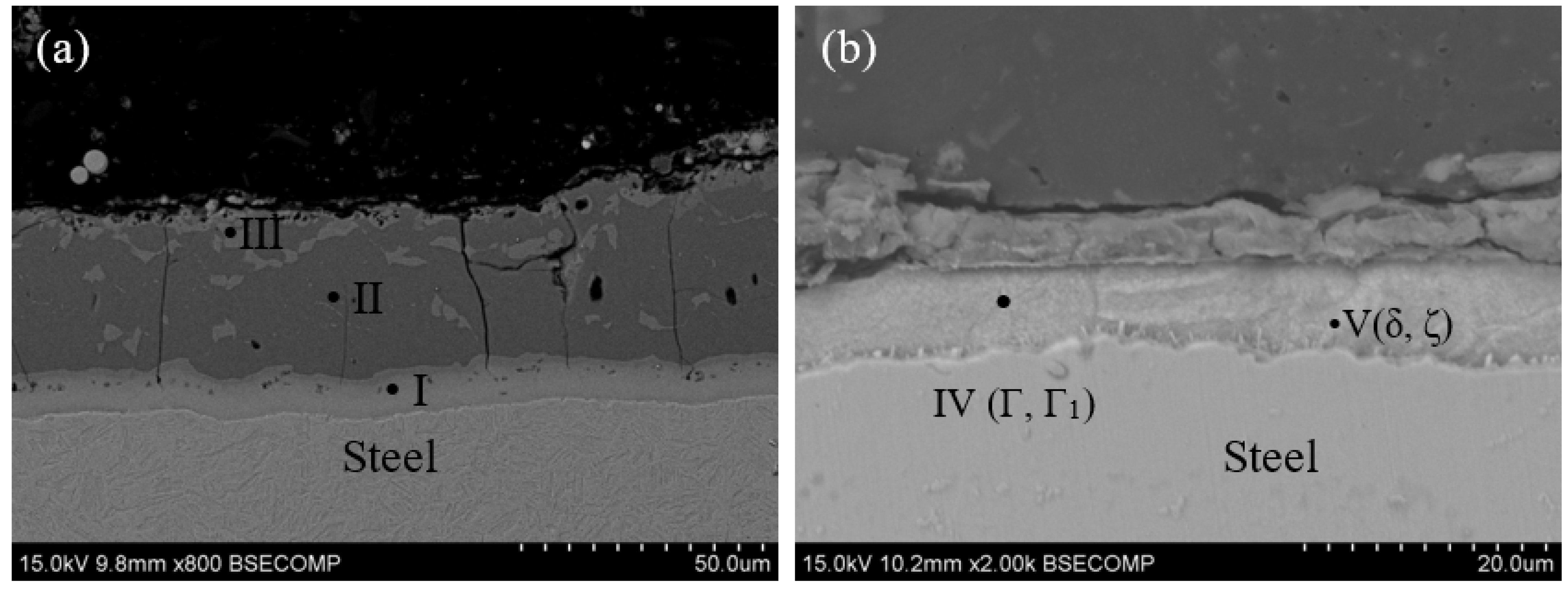
Figure 3.
Schematic diagram of laser welding added by Ni foil (unit: mm).
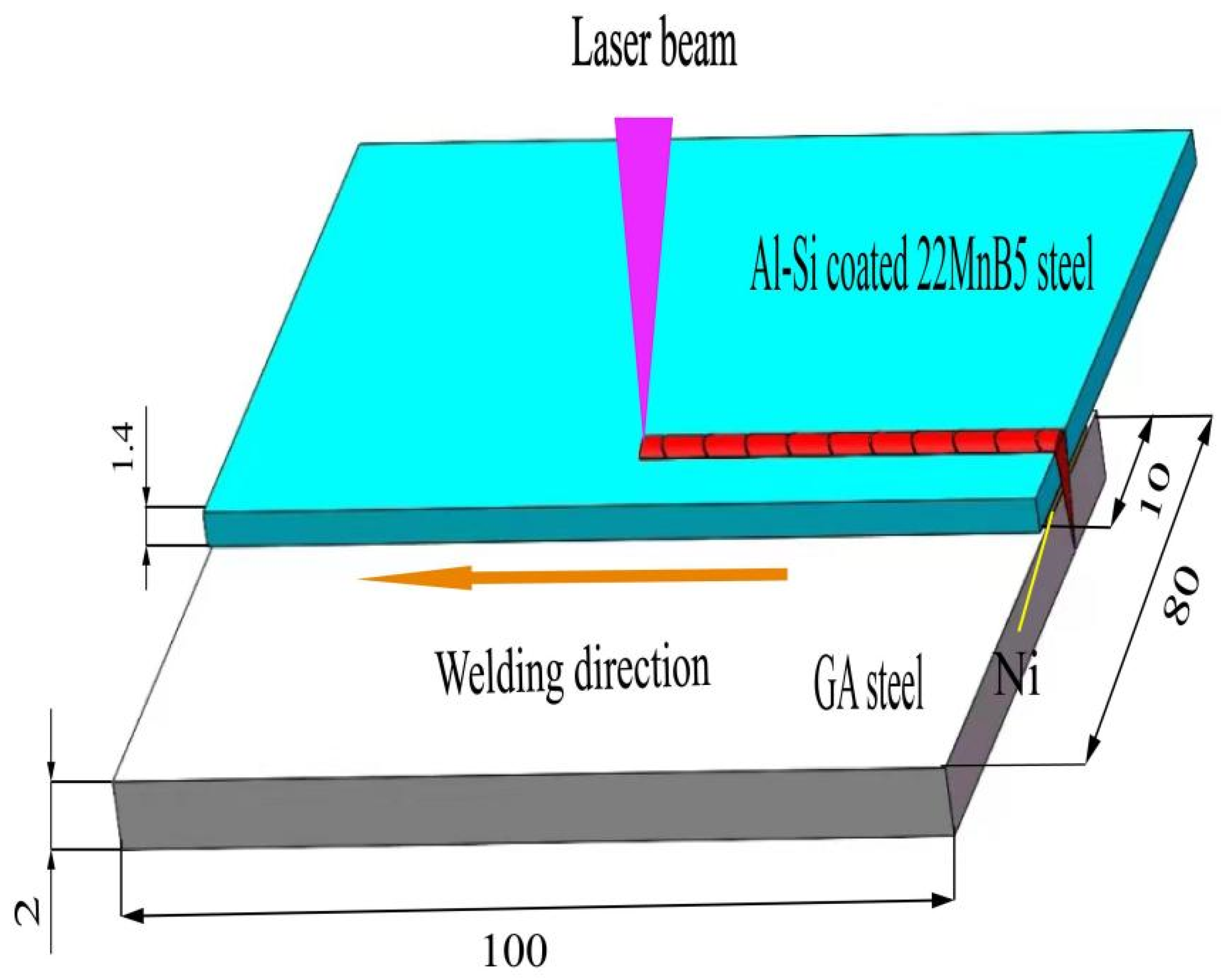
Figure 4.
Tensile shear specimen dimensions (unit: mm).
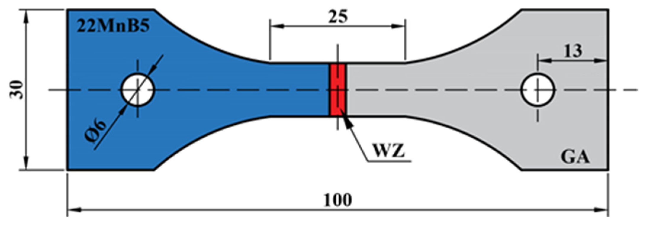
Figure 5.
Microstructure of fusion zone and fusion boundary under different thicknesses of nickel foil (a,d,g); (((b): FZ, (c): FB, Ni foil not added); ((e): FZ, (f): FB, 30 μm Ni foil); ((h): FZ, (i): FB, 100 μm Ni foil)).
Figure 5.
Microstructure of fusion zone and fusion boundary under different thicknesses of nickel foil (a,d,g); (((b): FZ, (c): FB, Ni foil not added); ((e): FZ, (f): FB, 30 μm Ni foil); ((h): FZ, (i): FB, 100 μm Ni foil)).

Figure 6.
SEM images of fusion zone and fusion boundary at different Ni foil thicknesses ((a): FZ, (b): FB, Ni foil not added); ((c): FZ, (d): FB, 30 μm Ni foil); ((e): FZ, (f): FB, 100 μm Ni foil)).
Figure 6.
SEM images of fusion zone and fusion boundary at different Ni foil thicknesses ((a): FZ, (b): FB, Ni foil not added); ((c): FZ, (d): FB, 30 μm Ni foil); ((e): FZ, (f): FB, 100 μm Ni foil)).
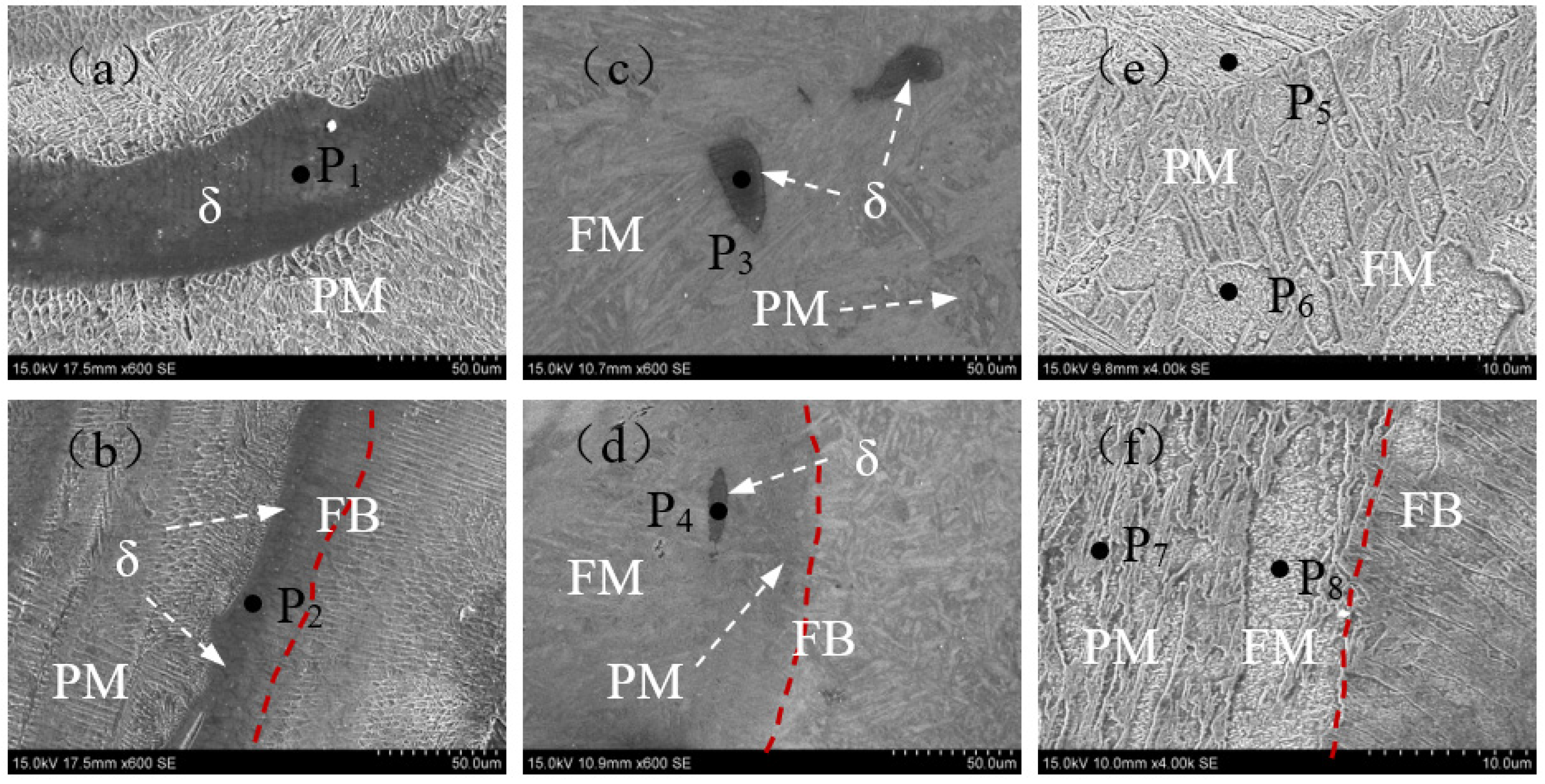
Figure 7.
Schematic diagram of weld pool flow ((a,b) Ni foil not added; (c,d) 100 μm Ni foil).
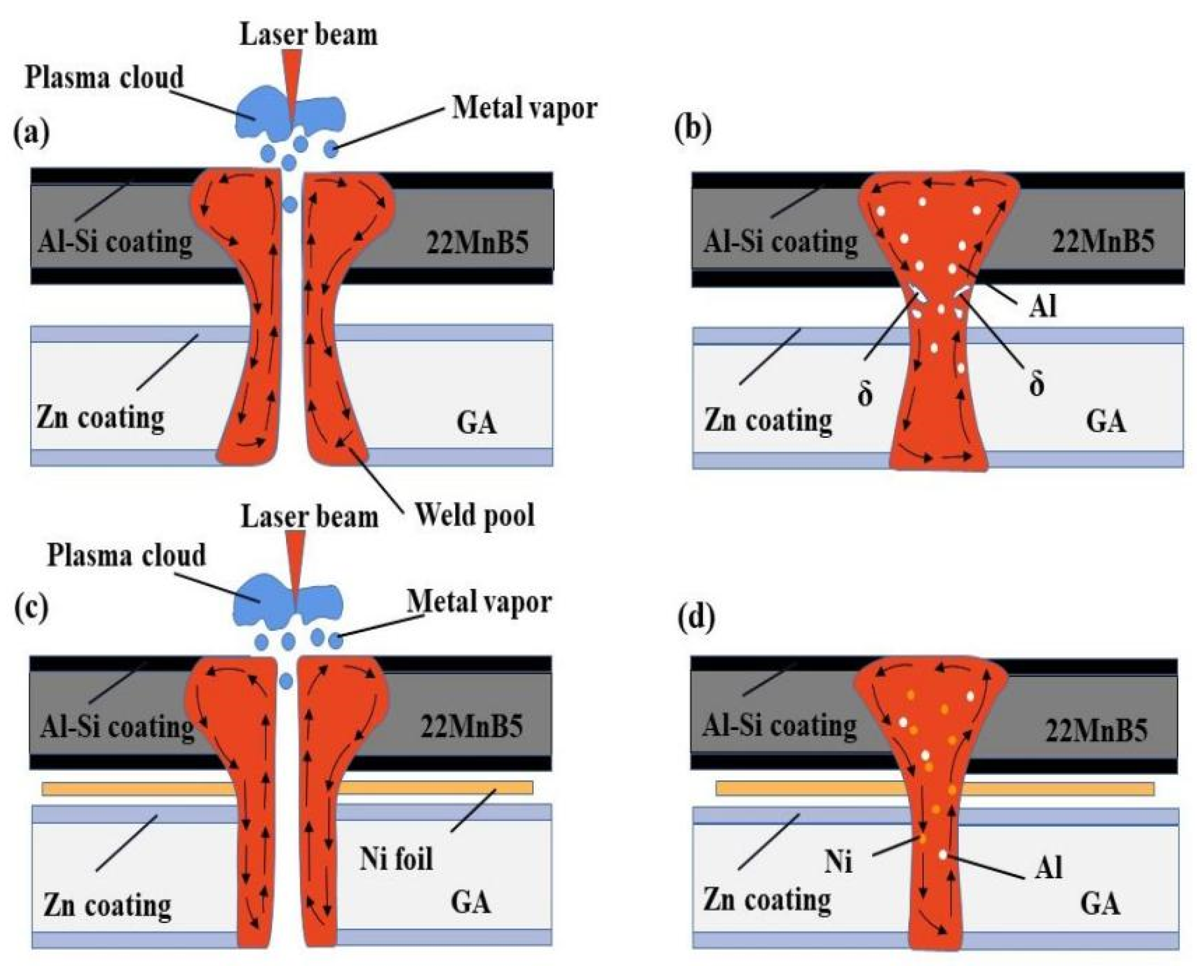
Figure 8.
Schematic diagram of tissue phase transition ((a): Ni foil not added; (b): 100 μm Ni foil).
Figure 8.
Schematic diagram of tissue phase transition ((a): Ni foil not added; (b): 100 μm Ni foil).
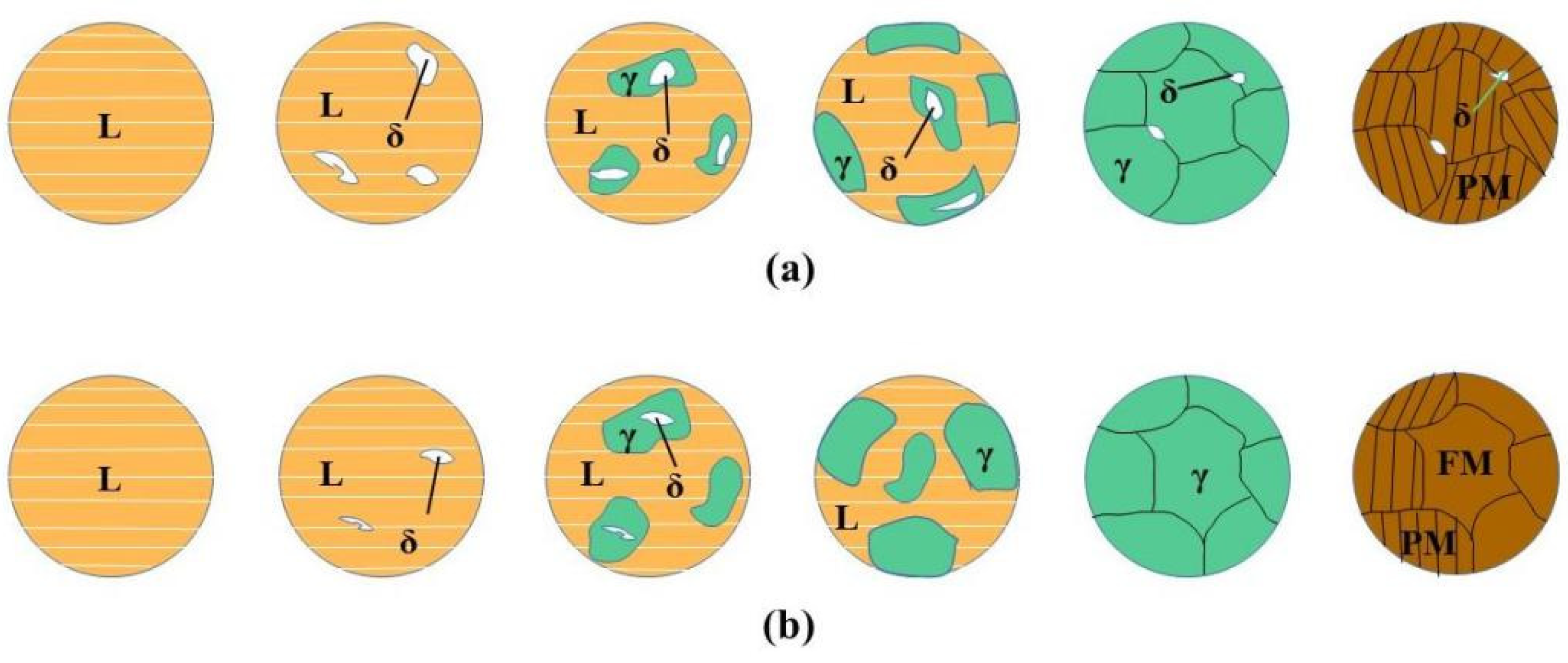
Figure 9.
Weld microstructures and hardness profiling (No.3 ) (a) over view; (b) coarse grain zone and refined zone; (c) intercritical zone and tempered zone; (d) HAZ-GA; (e) hardness profile.
Figure 9.
Weld microstructures and hardness profiling (No.3 ) (a) over view; (b) coarse grain zone and refined zone; (c) intercritical zone and tempered zone; (d) HAZ-GA; (e) hardness profile.
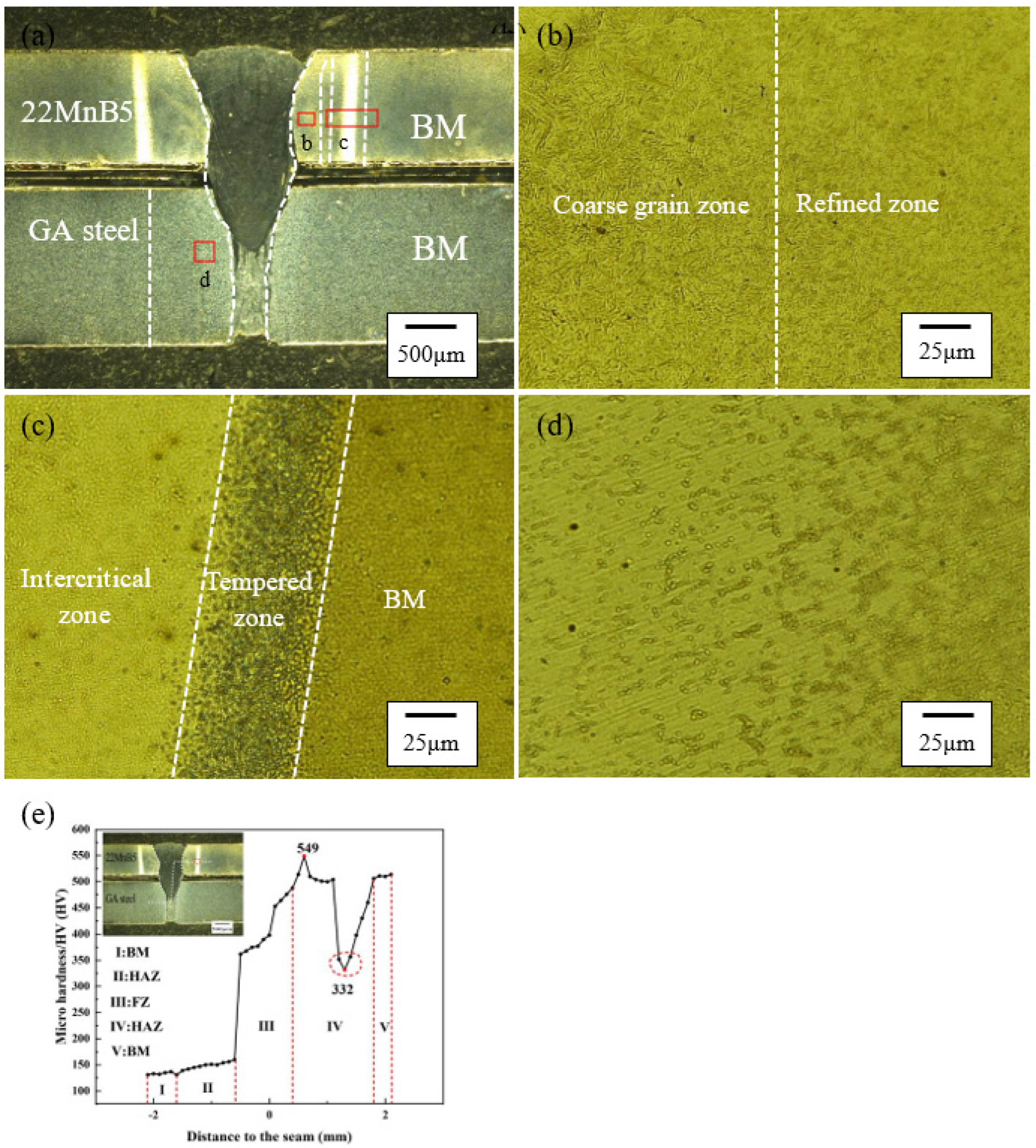
Figure 10.
Tensile shear strength at different thicknesses of Ni foil.
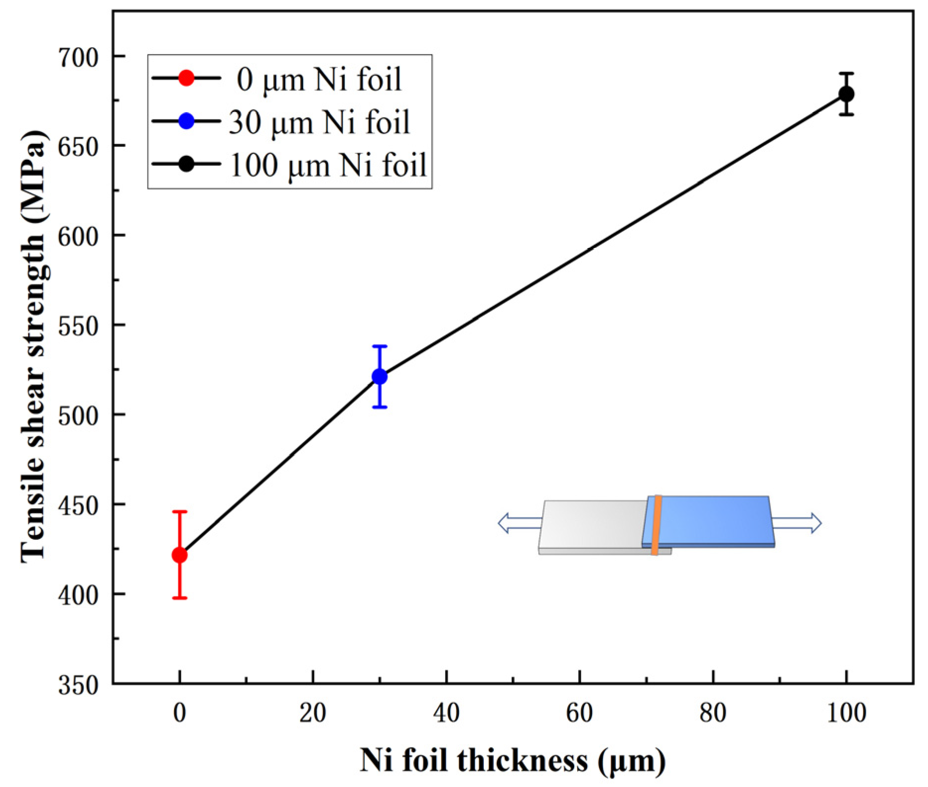
Figure 11.
Tensile fracture surface SEM morphologies at various nickel foil thicknesses ((a–c): Ni foil not added; (d–f): 30 μm Ni foil; (g–i): 100 μm Ni foil).
Figure 11.
Tensile fracture surface SEM morphologies at various nickel foil thicknesses ((a–c): Ni foil not added; (d–f): 30 μm Ni foil; (g–i): 100 μm Ni foil).


Table 1.
Chemical compositions (wt.%) and tensile properties of base materials.
| Chemical Compositions (wt.%) | Tensile Properties | ||||||||||
|---|---|---|---|---|---|---|---|---|---|---|---|
| BM | C | Mn | Si | Cr | B | Ti | Al | Fe | UTS (Mpa) | YS (Mpa) | Elongations (%) |
| 22MnB5 | 0.23 | 1.13 | 0.27 | 0.16 | 0.0025 | 0.038 | 0.037 | Bal | 1500 | 1200 | 4.1 |
| GA steel | 0.041 | 0.187 | 0.018 | 0.04 | — | 0.011 | 0.0032 | Bal | 350 | 300 | 11.5 |
Table 2.
Weld profile and width at different thicknesses of Ni foil.
| No. | Laser Power (kW) | Welding Speed (m·min−1) | Ni Foil Thickness (μm) | B1 (mm) | B2 (mm) | B3 (mm) | Cross-Section |
|---|---|---|---|---|---|---|---|
| 1 | 3 | 2 | — | 1.61 | 1.25 | 1.12 | 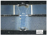 |
| 2 | 3 | 2 | 30 | 1.57 | 1.03 | 0.67 | 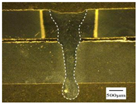 |
| 3 | 3 | 2 | 100 | 1.55 | 1.08 | 0.51 | 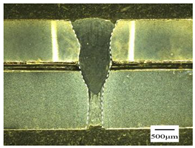 |
Table 3.
Chemical composition of different regions (wt.%).
| Component/wt.% | P1 | P2 | P3 | P4 | P5 | P6 | P7 | P8 |
|---|---|---|---|---|---|---|---|---|
| Al | 7.65 | 6.73 | 3.76 | 3.11 | 0.72 | 0.63 | 0.86 | 0.90 |
| Si | 0.98 | 0.75 | 0.89 | 0.54 | 0.46 | 0.23 | 0.31 | 0.02 |
| Ni | 0.12 | 0.18 | 2.72 | 1.40 | 1.35 | 4.81 | 1.42 | 3.27 |
| Fe | Bal. | Bal. | Bal. | Bal. | Bal. | Bal. | Bal. | Bal. |
Table 4.
Summary of transformation pathways and the resultant microstructure in the heat-affected zone.
Table 4.
Summary of transformation pathways and the resultant microstructure in the heat-affected zone.
| Zone | Critical Temperature | Phase Transition Process | |
|---|---|---|---|
| heat affected zone (22MnB5) | Coarse grain zone | Ac3 < T < 1100 °C | M → γ → M |
| Refined zone | 1100 °C < T < TL | ||
| Incompletely quenched zone | Ac1 < T < Ac3 | M → γ + α-Fe → M + α-Fe | |
| Tempering zone | Ttemper < T < Ac1 | M → TM | |
| heat affected zone (GA) | Incompletely recrystallized zone | Ac1 < T | α-Fe + P → γ + α-Fe + P → F + P |
Table 5.
Tensile strength and fracture location.
| NO | Ni Foil Thickness (μm) | Tensile Shear Load (N) | Section Size B × H (mm2) | Tensile Shear Strength (MPa) | Fracture Location |
|---|---|---|---|---|---|
| 0 | _ | 4569 | 1.1 × 10 | 412 | FB |
| 1 | 30 | 6242 | 1.2 × 10 | 521 | FB |
| 2 | 100 | 6245 | 0.92 × 10 | 679 | Interface |
Table 6.
Chemical components of the fracture surfaces (wt.%).
| Element/wt.% | E1 | E2 | E3 | E4 | E5 | E6 |
|---|---|---|---|---|---|---|
| Al | 8.07 | 3.05 | 1.12 | 2.04 | 1.08 | 0.30 |
| Si | 0.65 | 0.71 | 0.52 | 0.74 | 0.88 | 0.16 |
| Ni | — | — | — | 1.44 | 2.59 | 8.07 |
| Fe | Bal. | Bal. | Bal. | Bal. | Bal. | Bal. |
Disclaimer/Publisher’s Note: The statements, opinions and data contained in all publications are solely those of the individual author(s) and contributor(s) and not of MDPI and/or the editor(s). MDPI and/or the editor(s) disclaim responsibility for any injury to people or property resulting from any ideas, methods, instructions or products referred to in the content. |
© 2023 by the authors. Licensee MDPI, Basel, Switzerland. This article is an open access article distributed under the terms and conditions of the Creative Commons Attribution (CC BY) license (https://creativecommons.org/licenses/by/4.0/).
Share and Cite
MDPI and ACS Style
Zhang, Y.; Qin, Y.; Zhao, F.; Liang, M. Improving the Microstructure and Mechanical Properties of Laser-Welded Al–Si-Coated 22MnB5/Galvanized Steel Joints Added by Nickel. Metals 2023, 13, 1600. https://doi.org/10.3390/met13091600
AMA Style
Zhang Y, Qin Y, Zhao F, Liang M. Improving the Microstructure and Mechanical Properties of Laser-Welded Al–Si-Coated 22MnB5/Galvanized Steel Joints Added by Nickel. Metals. 2023; 13(9):1600. https://doi.org/10.3390/met13091600
Chicago/Turabian StyleZhang, Youping, Youqiong Qin, Feng Zhao, and Min Liang. 2023. "Improving the Microstructure and Mechanical Properties of Laser-Welded Al–Si-Coated 22MnB5/Galvanized Steel Joints Added by Nickel" Metals 13, no. 9: 1600. https://doi.org/10.3390/met13091600
Note that from the first issue of 2016, this journal uses article numbers instead of page numbers. See further details here.