

Adjustable Elasticity of Anatomically Shaped Lattice Bone Scaffold Built by Electron Beam Melting Ti6Al4V Powder
 , , and
Abstract
:1. Introduction
- Reinforcing the liquid material of the bone graft, which, similar to its own provisional bone tissue, should transform during the recovery process into mature and healthy bone tissue and connect with the surrounding bone.
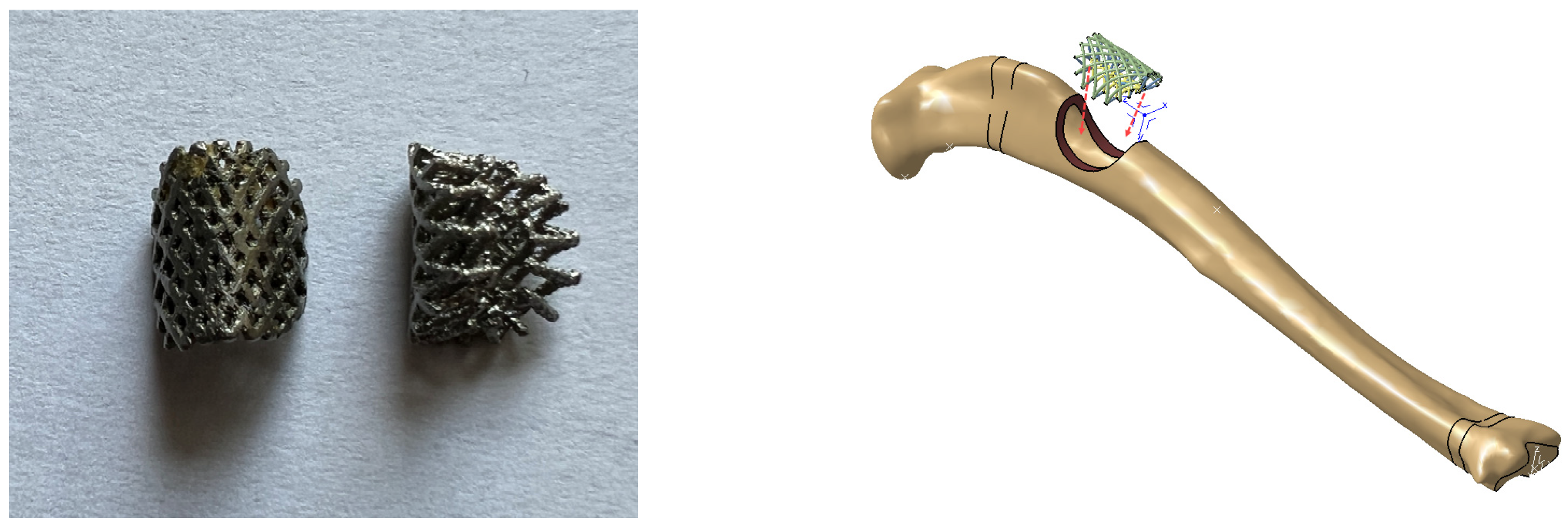
- Forming the volume of the bone graft into the desired anatomical shape of the future bone tissue, corresponding to the anatomy of the missing bone part.
- Enabling the targeted elastic deformation of the volume of the bone graft is crucial for the design of an ASLS. In fact, the elasticity of the ASLS needs to adapt to the loading that the patient’s bone will undergo during recovery. The appropriate elastic deformation, or strain, of the ASLS and the bone graft within is of utmost importance for accelerating the process of ossification (bone formation) or transformation of provisional bone tissue into mature bone tissue. Therefore, one of the goals of designing the ASLS is to ensure the desired strain, i.e., the targeted elastic deformation of the ASLS for the most common loading scenario during recovery, through suitable design and construction.
2. Materials and Methods
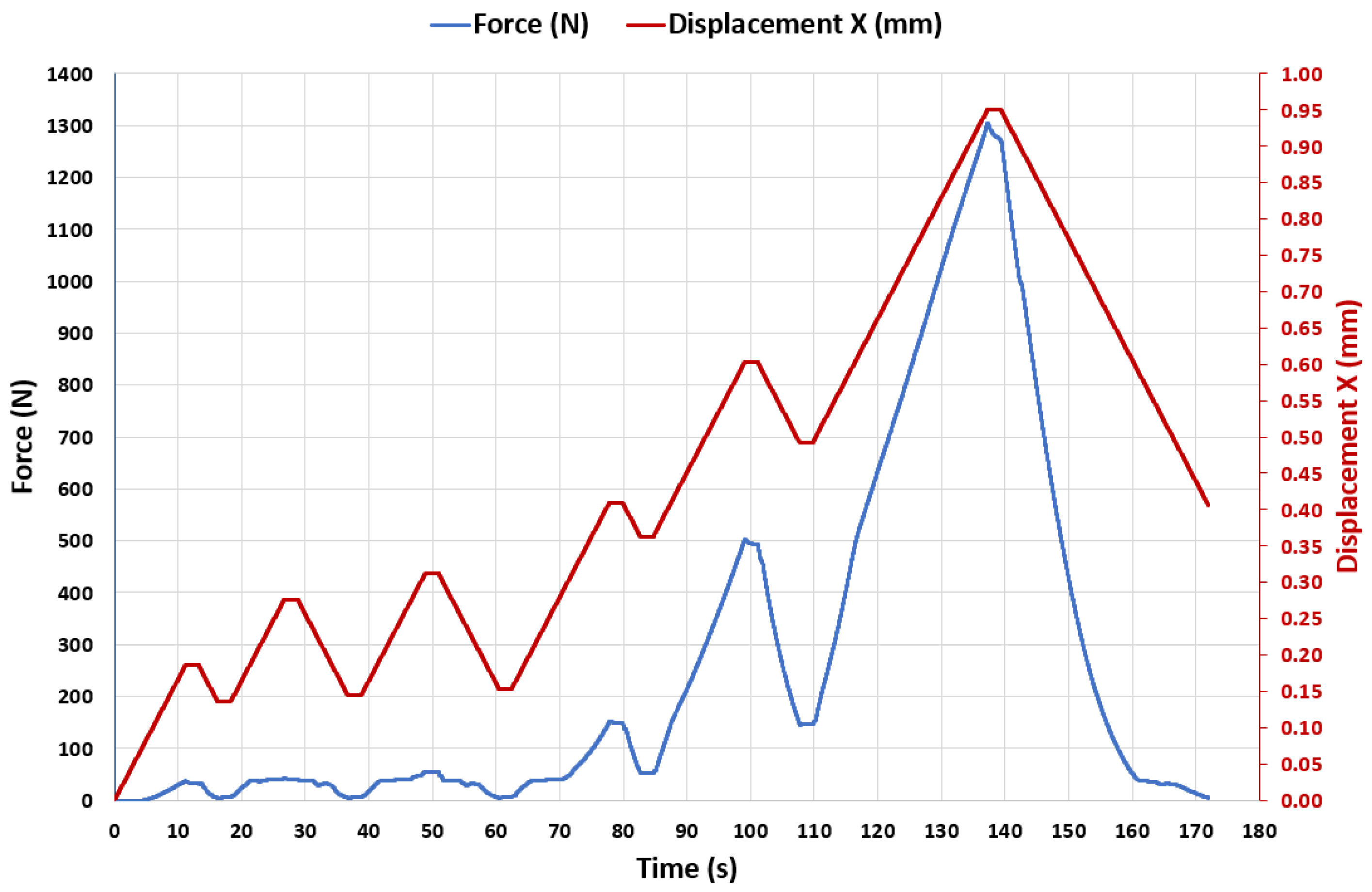
- the scaffold was compressed up to a certain force, once this force was achieved it was maintained for 2 s,
- next, the scaffold was unloaded down to a force smaller than that of the previous step (not zero, to keep the scaffold in contact with the fixtures), once this force was achieved, it was maintained for 2 s.
3. Results
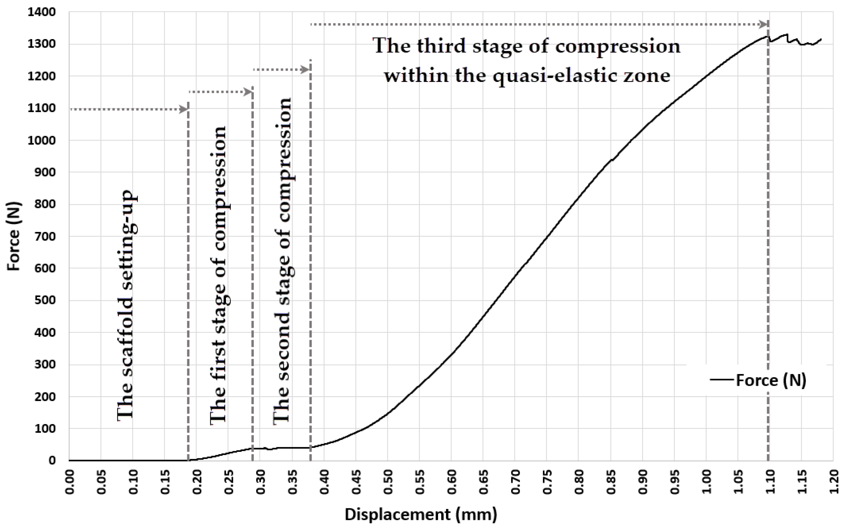
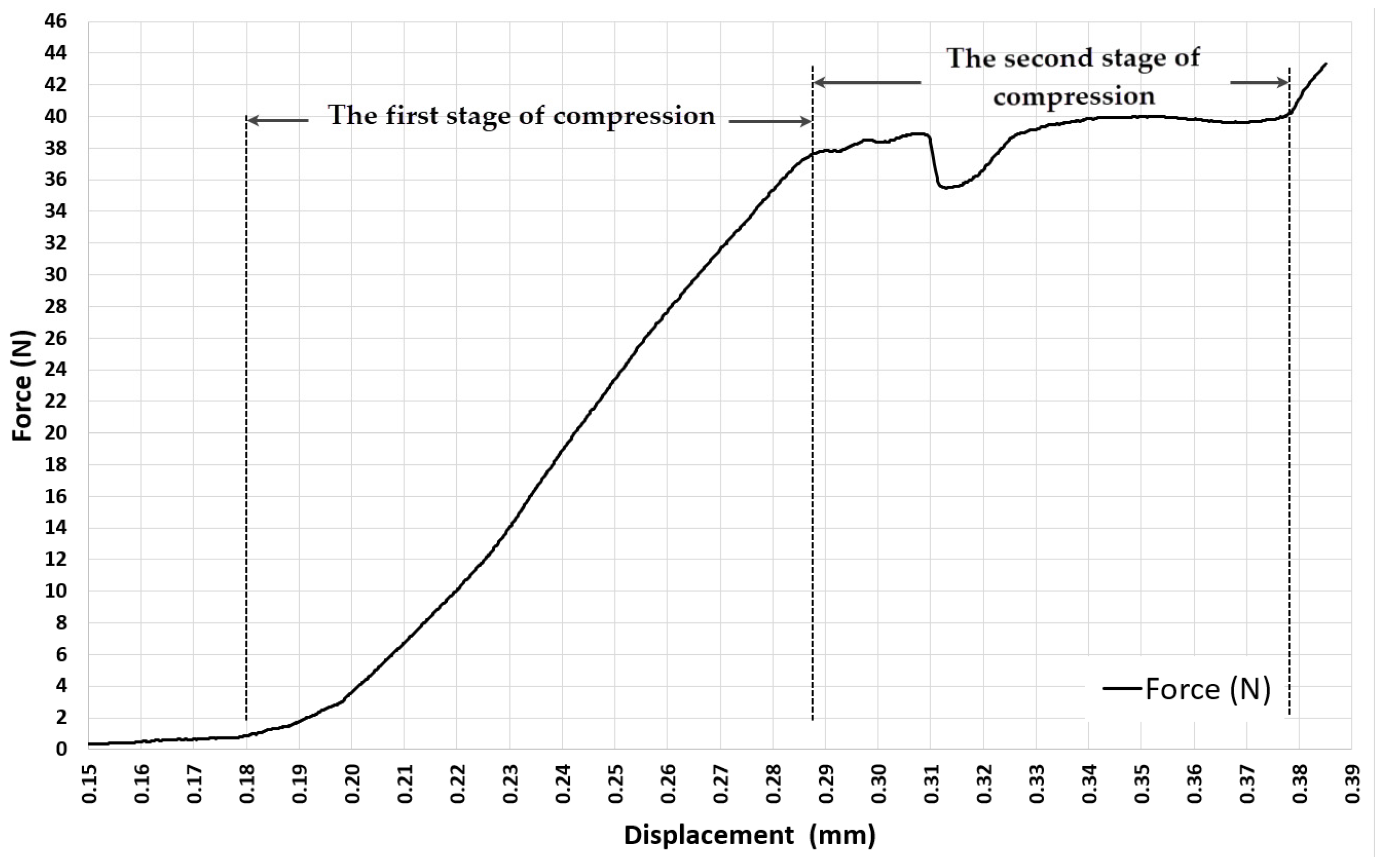
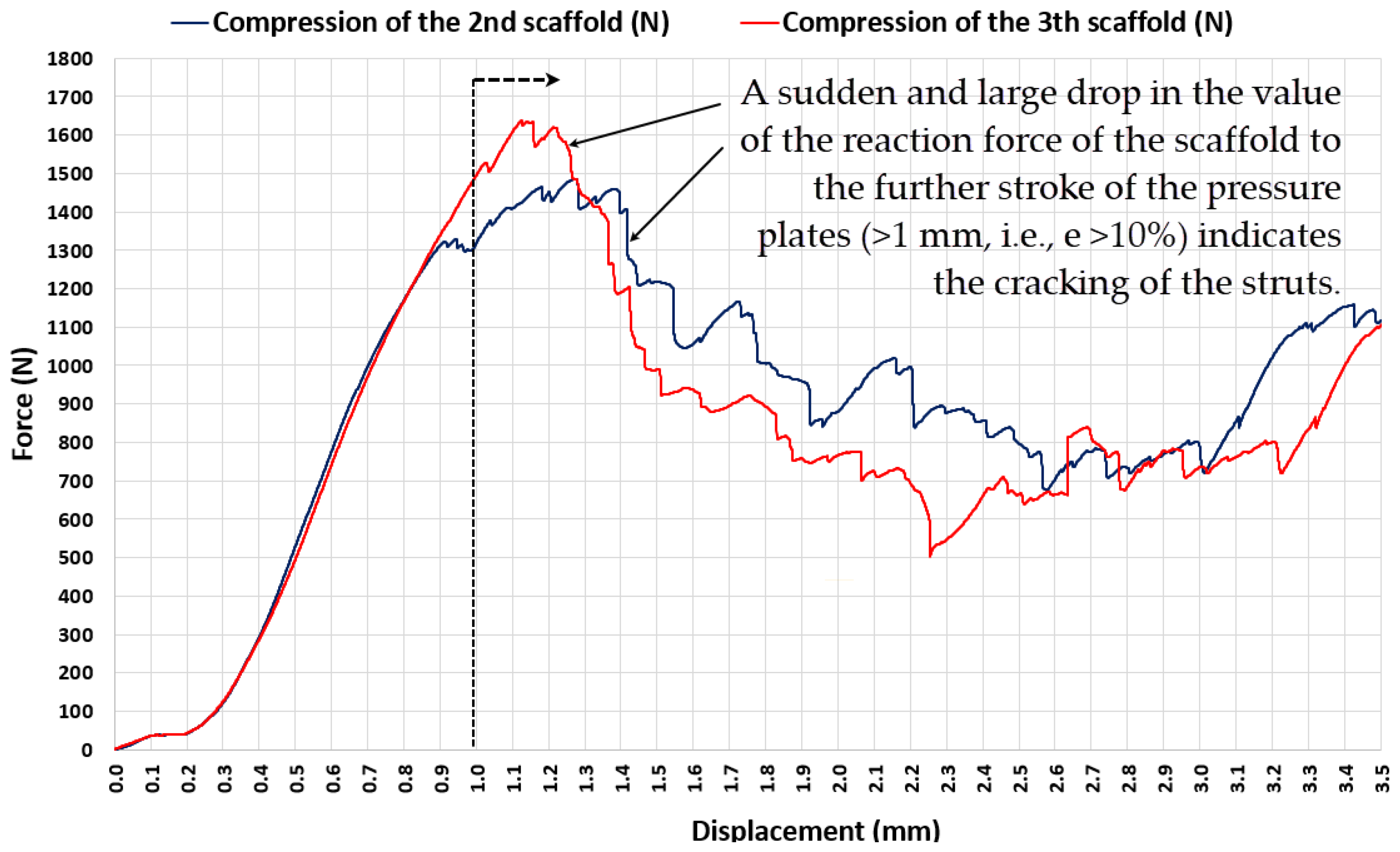
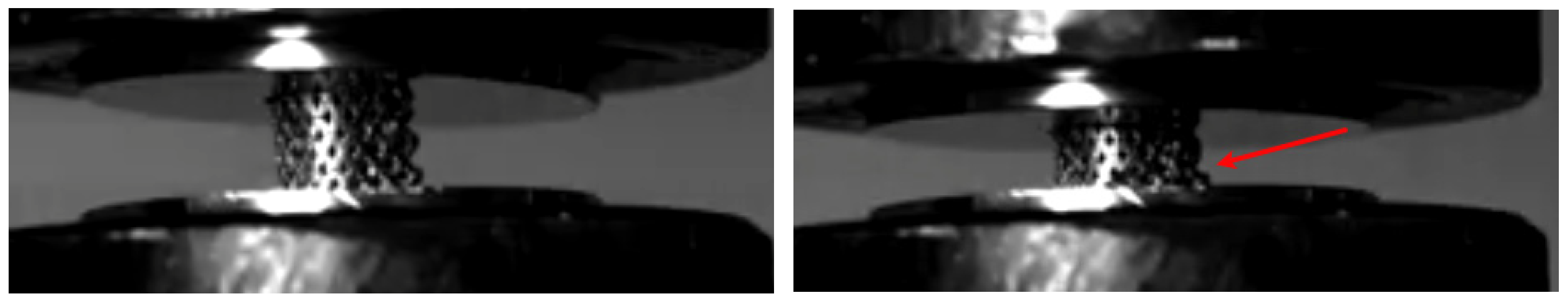
3.1. Experiment 1-Determining the Whole Range of Compression, up to 35% Deformation of Initial Length of ASLS (dx = 3.5 mm, Xo = 10 mm)
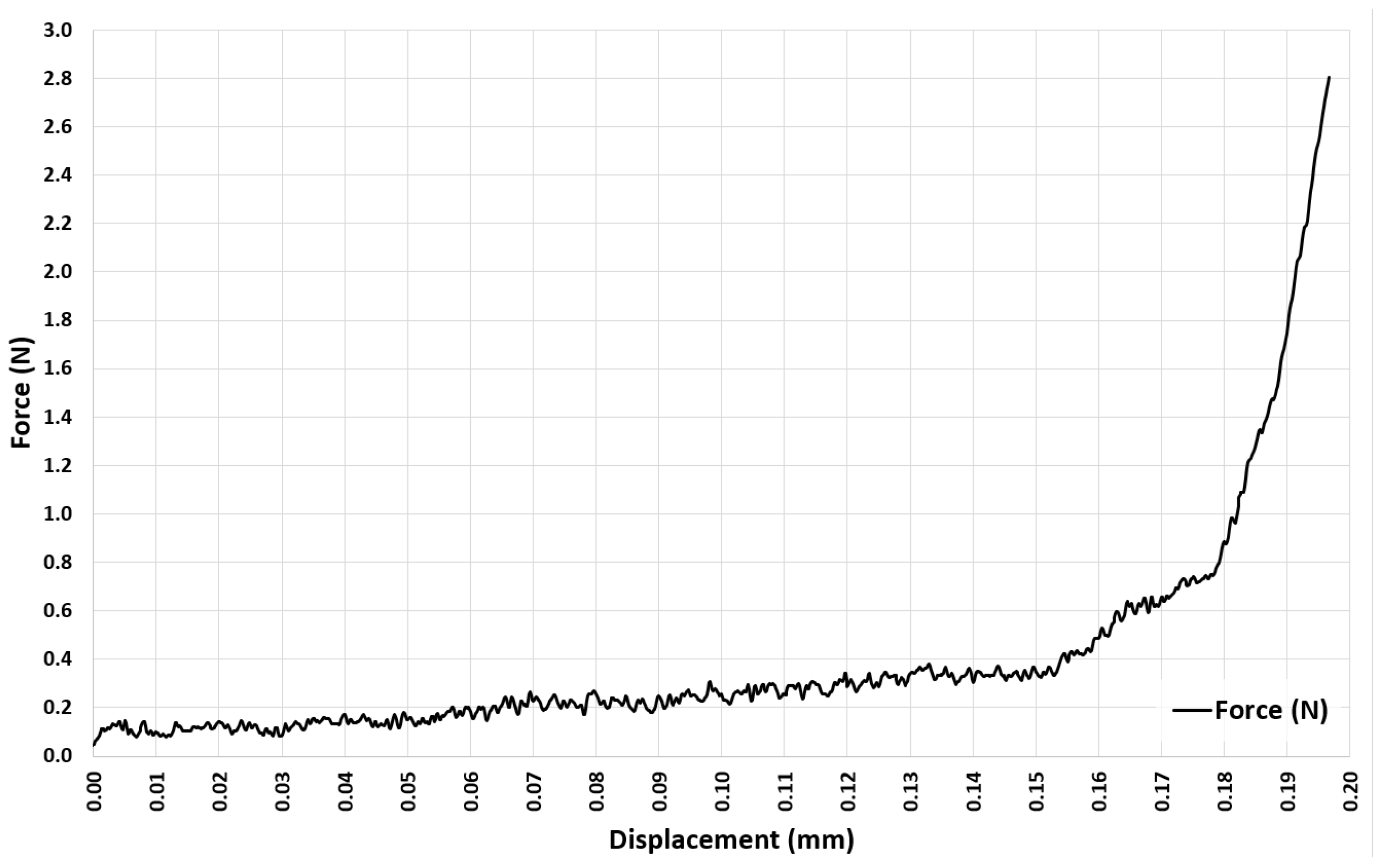
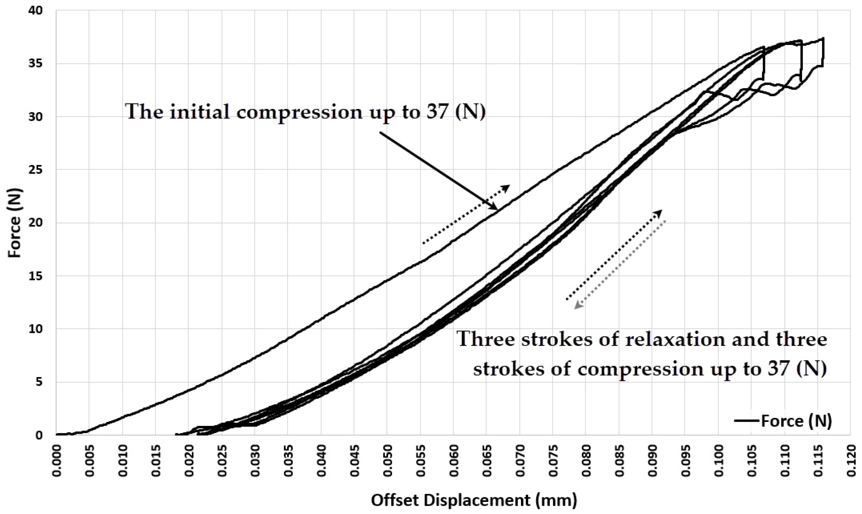
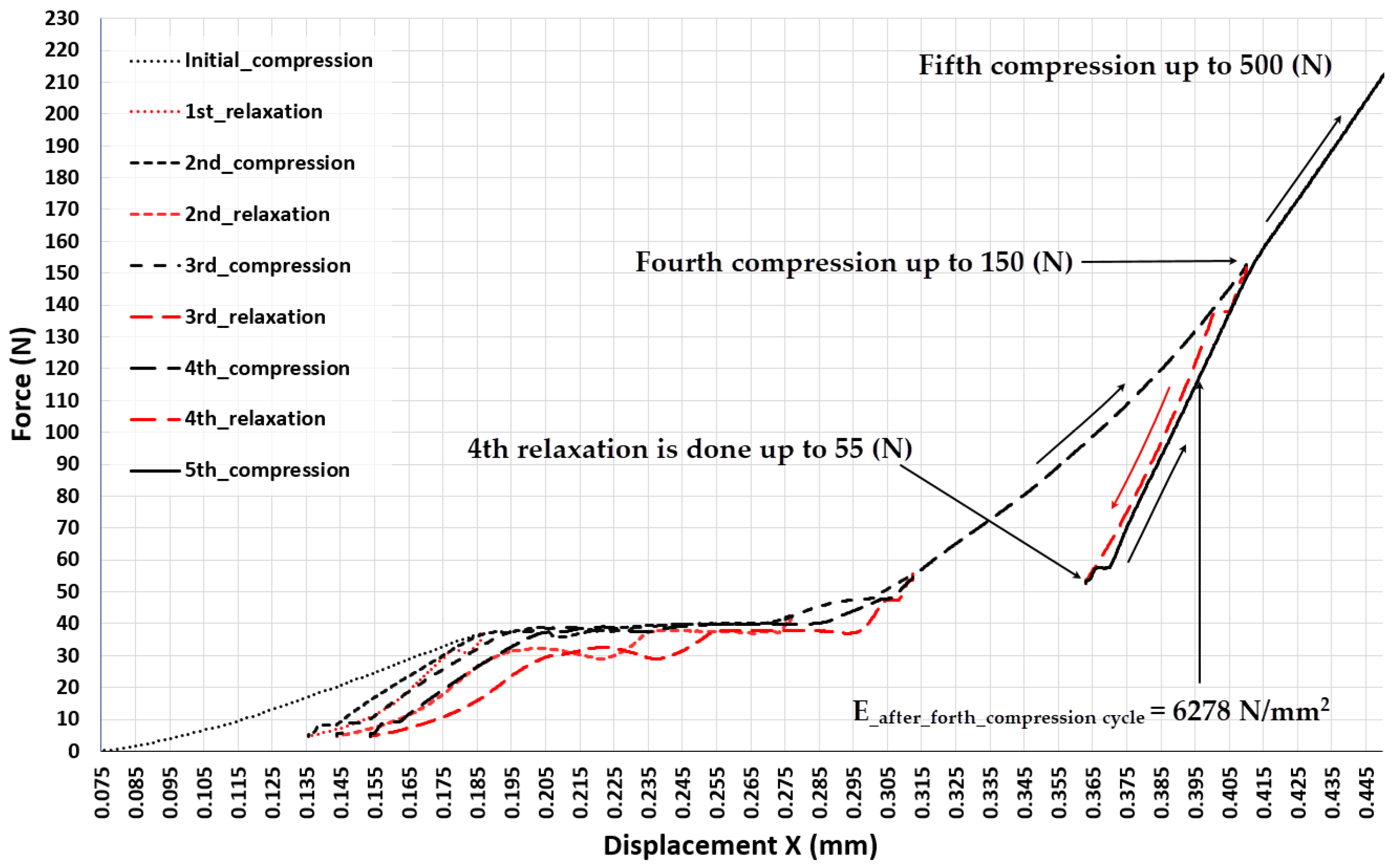
3.2. Experiment 2–Exploring the Quasi-Elastic Properties of the ASLS for the First Compression Stage
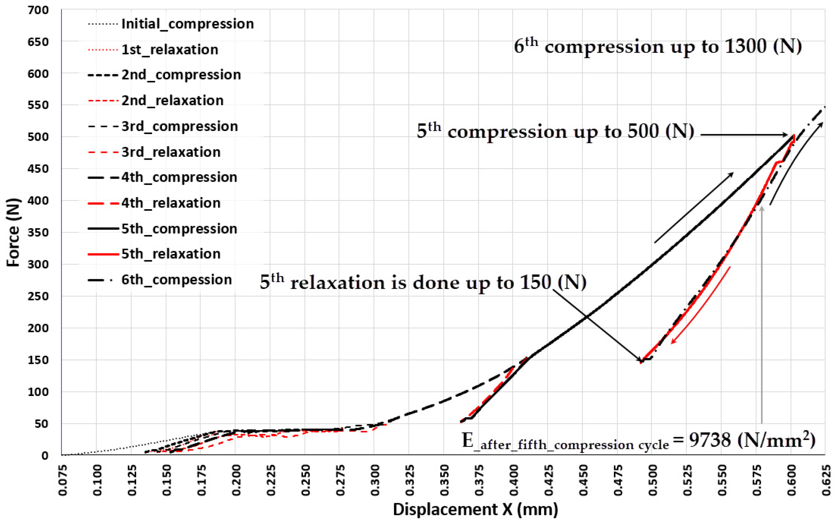
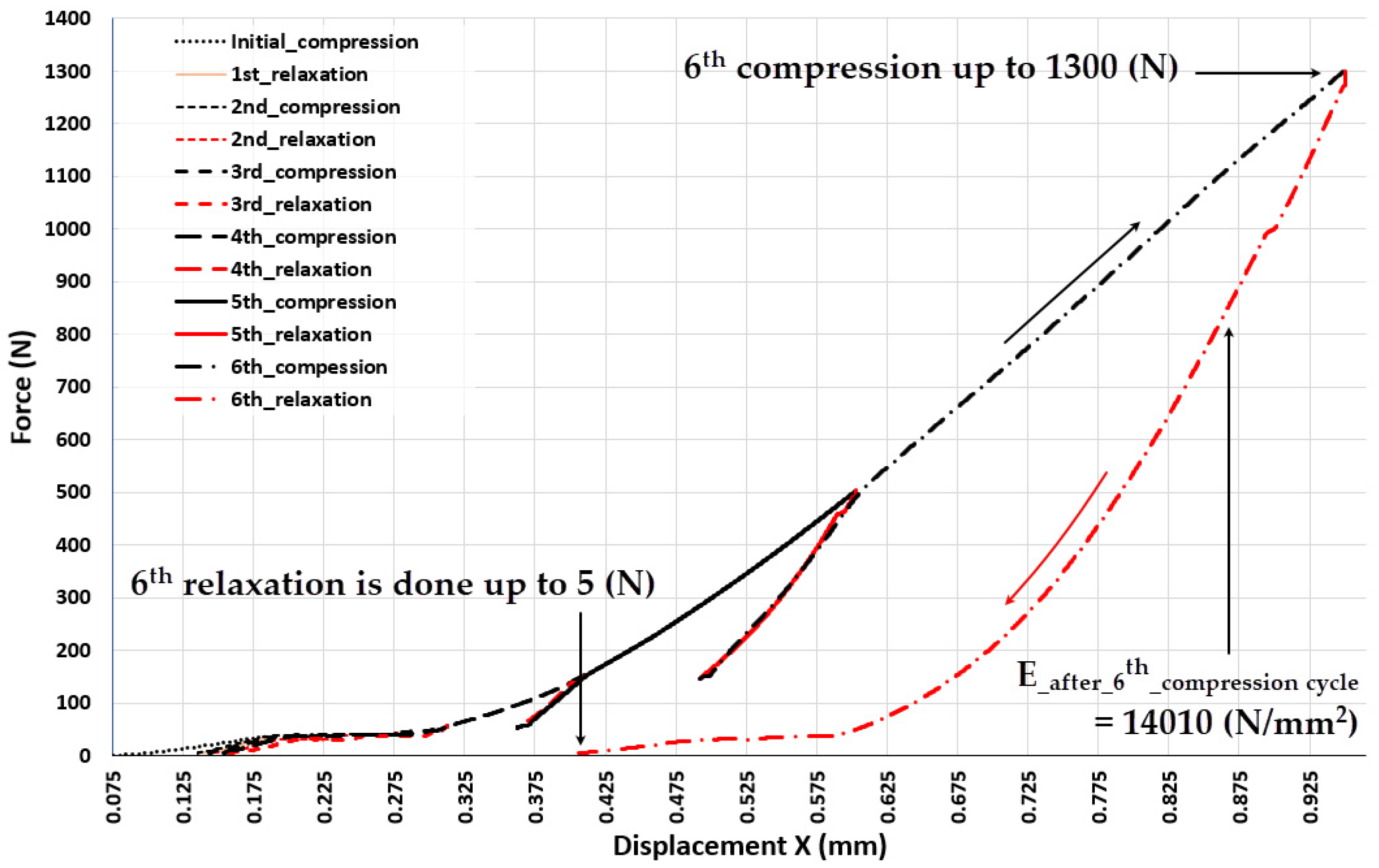
3.3. Experiment 3-Exploring the Quasi-Elastic Properties of the ASLS throughout the Entire Range of Compression, Including the Second and Third Compression Stages
4. Discussion
5. Conclusions
- Lattice scaffolds, produced using the EBM additive manufacturing process with Ti6Al4V powder and intended for bone tissue recovery, exhibit the characteristic of plastic deformation even at low forces.
- Prior to the stresses in the struts of the EBM-built lattice scaffold reaching a value that causes structural cracking, compression induces three distinctive stages of elastic-plastic deformation. The most intriguing phenomenon accompanying each of these deformation phases is the high degree of reversibility of the scaffold deformation after relaxation, although the force-elongation relationship shows significant nonlinearity. After the initial exposure of the scaffold to the upper limit of the load characteristic for each of these three phases of compression, the scaffold becomes stiffer compared to the state before that initial load, and each subsequent cycle of loading and relaxation in each range (characteristic for that phase) allows the scaffold to behave quasi-elastic (deformations are almost completely reversible). This feature is recognized as very useful for the situation where the stiffness of the lattice scaffold needs to be adjusted to the load generated by a specific patient during recovery, thus adjusting the deformation of the bone graft inside the scaffold in order to maximize the rate of the ossification process.
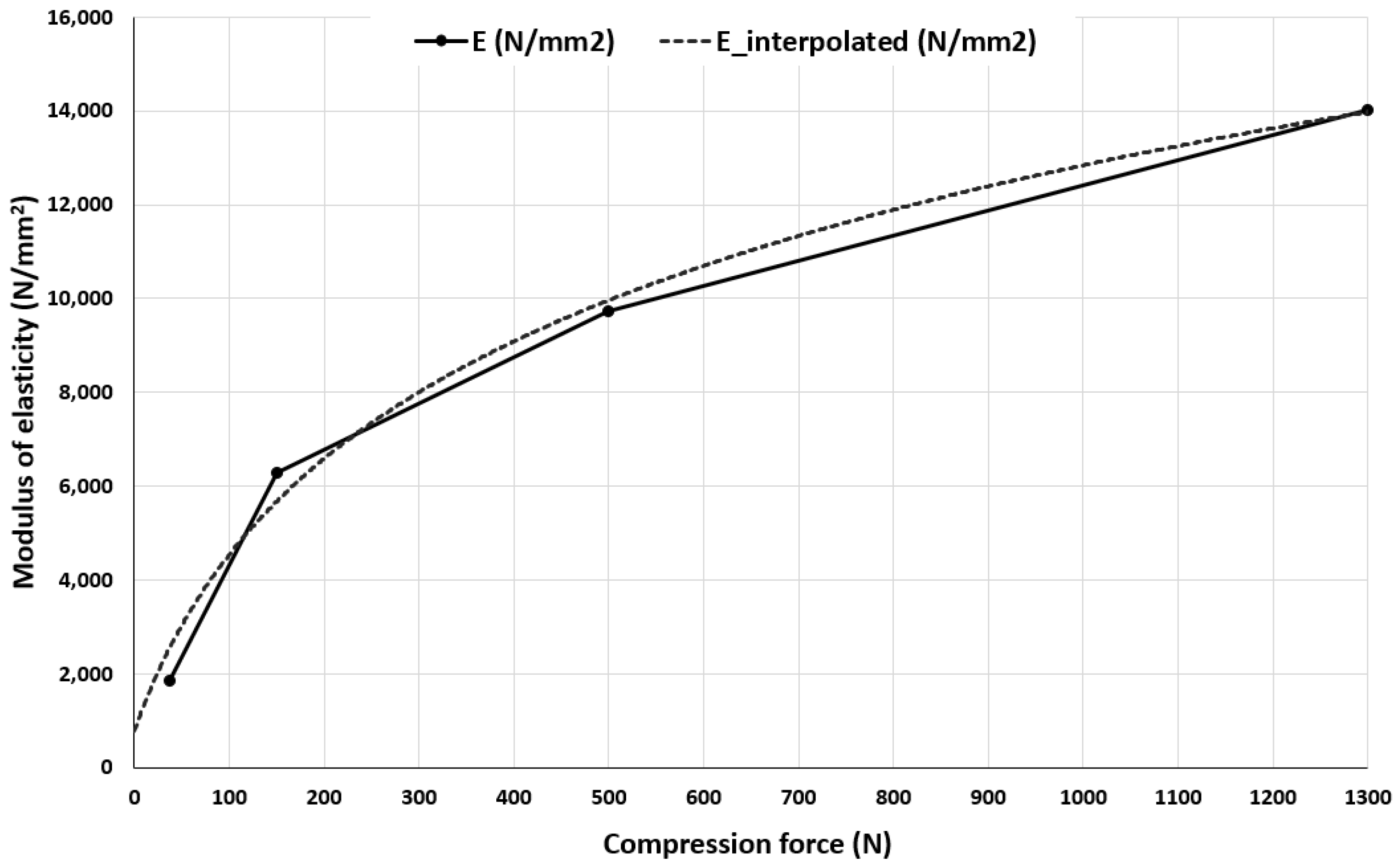
- The stiffness of ASLSs already manufactured using EBM with Ti6Al4V can be changed (improved) by applying an appropriate compression (stiffening) load to it, thus achieving the target elasticity of the scaffold structure.
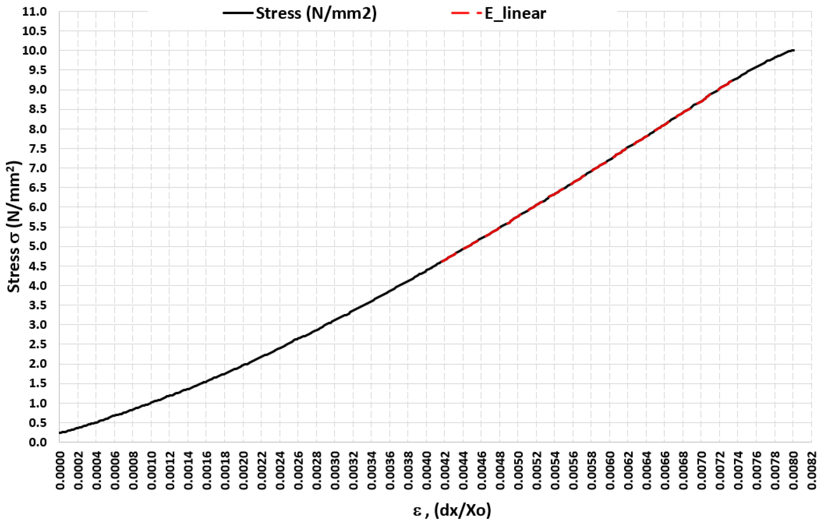
- The research established a functional relationship between the compression (stiffening) force and the alteration in the elastic modulus of ASLS. Given that ASLS is a unique form of a lattice scaffold, the technique for measurement and data processing capable of determining this functional relationship, as showcased in the paper, holds a broader universal significance.
Author Contributions
Funding
Data Availability Statement
Acknowledgments
Conflicts of Interest
References
- Trevisan, F.; Calignano, F.; Aversa, A.; Marchese, G.; Lombardi, M.; Biamino, S.; Ugues, D.; Manfredi, D. Additive manufacturing of titanium alloys in the biomedical field: Processes, properties and applications. J. Appl. Biomater. Funct. Mater. 2018, 16, 57–67. [Google Scholar] [CrossRef] [PubMed]
- Jung, H.-D. Titanium and Its Alloys for Biomedical Applications. Metals 2021, 11, 1945. [Google Scholar] [CrossRef]
- Sidhu, A.S. Surface Texturing of Non-Toxic, Biocompatible Titanium Alloys via Electro-Discharge. Rep. Mech. Eng. 2021, 2, 51–56. [Google Scholar] [CrossRef]
- Turek, P.; Jońca, K.; Winiarska, M. Evaluation of the Accuracy of the Resection Template and Restorations of the Bone Structures in the Mandible Area Manufactured Using the Additive Technique. Rep. Mech. Eng. 2023, 4, 39–46. [Google Scholar] [CrossRef]
- Van der Stok, J.; Van der Jagt, O.P.; Amin Yavari, S.; De Haas, M.F.; Waarsing, J.H.; Jahr, H.; Van Lieshout, E.M.; Patka, P.; Verhaar, J.A.; Zadpoor, A.A.; et al. Selective laser melting-produced porous titanium scaffolds regenerate bone in critical size cortical bone defects. J. Orthop. Res. 2013, 31, 792–799. [Google Scholar] [CrossRef]
- Sing, S.L.; An, J.; Yeong, W.Y.; Wiria, F.E. Laser and electron-beam powder-bed additive manufacturing of metallic implants: A review on processes, materials and designs. J. Orthop. Res. 2016, 34, 369–385. [Google Scholar] [CrossRef]
- Liu, S.; Shin, Y.C. Additive manufacturing of Ti6Al4V alloy: A review. Mater. Des. 2019, 164, 107552. [Google Scholar] [CrossRef]
- Tamayo, J.A.; Riascos, M.; Vargas, C.A.; Baena, L.M. Additive manufacturing of Ti6Al4V alloy via electron beam melting for the development of implants for the biomedical industry. Heliyon 2021, 7, e06892. [Google Scholar] [CrossRef]
- Dabrowski, B.; Swieszkowski, W.; Godlinski, D.; Kurzydlowski, K.J. Highly porous titanium scaffolds for orthopaedic applications. J. Biomed. Mater. Res. Part B Appl. Biomater. 2010, 95, 53–61. [Google Scholar] [CrossRef]
- Tshephe, T.S.; Akinwamide, S.O.; Olevsky, E.; Olubambi, P.A. Additive manufacturing of titanium-based alloys—A review of methods, properties, challenges, and prospects. Heliyon 2022, 8, e09041. [Google Scholar] [CrossRef]
- Acquesta, A.; Monetta, T. As-Built EBM and DMLS Ti-6Al-4V Parts: Topography–Corrosion Resistance Relationship in a Simulated Body Fluid. Metals 2020, 10, 1015. [Google Scholar] [CrossRef]
- Hu, J.; Wang, Y.; Fan, M.; Yao, Q.; Zheng, P. The comparison of properties of Ti-6Aluminum-4Vanadium porous scaffolds fabricated through low-power selective laser Melting and electron beam melting. Digit. Med. 2022, 8, 12. [Google Scholar] [CrossRef]
- Milovanović, J.; Stojković, M.; Trifunović, M.; Vitković, N. Review of Bone Scaffold Design Concepts and Design Methods. Facta Univ. Ser. Mech. Eng. 2023, 21, 151–173. [Google Scholar] [CrossRef]
- Li, B.; Hesar, B.D.; Zhao, Y.; Ding, L. Design and additive manufacturing of porous titanium scaffolds for optimum cell viability in bone tissue engineering. Proc. Inst. Mech. Eng. Part B J. Eng. Manuf. 2020. [Google Scholar] [CrossRef]
- Gürkan, D.; Sagbas, B.; Dalbayrak, B. Investigating mechanical and biological properties of additive manufactured Ti6Al4V lattice structures for orthopedic implants. J. Mater. Res. 2023, 38, 507–518. [Google Scholar] [CrossRef]
- Hudák, R.; Schnitzer, M.; Králová, Z.O.; Gorejová, R.; Mitrík, L.; Rajťúková, V.; Tóth, T.; Kovačević, M.; Riznič, M.; Oriňaková, R.; et al. Additive Manufacturing of Porous Ti6Al4V Alloy: Geometry Analysis and Mechanical Properties Testing. Appl. Sci. 2021, 11, 2611. [Google Scholar] [CrossRef]
- Bari, K. Design, Simulation, and Mechanical Testing of 3D-Printed Titanium Lattice Structures. J. Compos. Sci. 2023, 7, 32. [Google Scholar] [CrossRef]
- Galarraga, H.; Lados, D.A.; Dehoff, R.R.; Kirka, M.M.; Nandwana, P. Effects of the microstructure and porosity on properties of Ti-6Al-4V ELI alloy fabricated by electron beam melting (EBM). Addit. Manuf. 2016, 10, 47–57. [Google Scholar] [CrossRef]
- Distefano, F.; Pasta, S.; Epasto, G. Titanium Lattice Structures Produced via Additive Manufacturing for a Bone Scaffold: A Review. J. Funct. Biomater. 2023, 14, 125. [Google Scholar] [CrossRef]
- Raheem, A.A.; Hameed, P.; Whenish, R.; Elsen, R.S.; G, A.; Jaiswal, A.K.; Prashanth, K.G.; Manivasagam, G. A Review on Development of Bio-Inspired Implants Using 3D Printing. Biomimetics 2021, 6, 65. [Google Scholar] [CrossRef]
- Mondal, P.; Das, A.; Mondal, A.; Chowdhury, A.R.; Karmakar, A. Fabrication of Ti-6Al-4V Porous Scaffolds Using Selective Laser Melting (SLM) and Mechanical Compression Test for Biomedical Applications. J. Inst. Eng. (India) Ser. D 2022, 103, 181–190. [Google Scholar] [CrossRef]
- Loginov, Y.N.; Koptyug, A.; Popov, V.V.; Belikov, S.V.; Mukanov, G.; Golodnov, A.I.; Stepanov, S.I. Compression deformation and fracture behavior of additively manufactured Ti–6Al–4V cellular structures. Int. J. Lightweight Mater. Manuf. 2022, 5, 126–135. [Google Scholar] [CrossRef]
- Dhiman, S.; Singh, M.; Sidhu, S.S.; Bahraminasab, M.; Pimenov, D.Y.; Mikolajczyk, T. Cubic Lattice Structures of Ti6Al4V under Compressive Loading: Towards Assessing the Performance for Hard Tissue Implants Alternative. Materials 2021, 14, 3866. [Google Scholar] [CrossRef]
- Zhang, C.; Zhang, L.; Liu, L.; Lv, L.; Gao, L.; Liu, N.; Wang, X.; Ye, J. Mechanical behavior of a titanium alloy scaffold mimicking trabecular structure. J. Orthop. Surg. Res. 2020, 15, 40. [Google Scholar] [CrossRef]
- Del Guercio, G.; Galati, M.; Saboori, A.; Fino, P.; Iuliano, L. Microstructure and Mechanical Performance of Ti–6Al–4V Lattice Structures Manufactured via Electron Beam Melting (EBM). Acta Metall. Sin. (Engl. Lett.) 2020, 33, 183–203. [Google Scholar] [CrossRef]
- Kotzem, D.; Arold, T.; Bleicher, K.; Raveendran, R.; Niendorf, T.; Walther, F. Ti6Al4V lattice structures manufactured by electron beam powder bed fusion—Microstructural and mechanical characterization based on advanced in situ techniques. J. Mater. Res. Technol. 2023, 22, 2111–2130. [Google Scholar] [CrossRef]
- Parthasarathy, J.; Starly, B.; Raman, S.; Christensen, A. Mechanical evaluation of porous titanium (Ti6Al4V) structures with electron beam melting (EBM). J. Mech. Behav. Biomed. Mater. 2010, 3, 249–259. [Google Scholar] [CrossRef]
- Zumofen, L.; Kopanska, K.S.; Bono, E.; Kirchheim, A.; De Haller, E.B.; Graf-Hausner, U. Properties of additive-manufactured open porous titanium structures for patient-specific load-bearing implants. Front. Mech. Eng. 2022, 7, 830126. [Google Scholar] [CrossRef]
- De Pasquale, G.; Luceri, F.; Riccio, M. Experimental Characterization of SLM and EBM Cubic Lattice Structures for Lightweight Applications. Exp. Mech. 2019, 59, 469–482. [Google Scholar] [CrossRef]
- Sepe, R.; De Luca, A.; Giannella, V.; Borrelli, R.; Franchitti, S.; Di Caprio, F.; Caputo, F. Influence of dimension, building position, and orientation on mechanical properties of EBM lattice Ti6Al4V trusses. Int. J. Adv. Manuf. Technol. 2022, 122, 3183–3198. [Google Scholar] [CrossRef]
- Suard, M.; Martin, G.; Lhuissier, P.; Dendievel, R.; Vignat, F.; Blandin, J.-J.; Villeneuve, F. Mechanical equivalent diameter of single struts for the stiffness prediction of lattice structures produced by Electron Beam Melting. Addit. Manuf. 2015, 8, 124–131. [Google Scholar] [CrossRef]
- Cansizoglu, O.; Harrysson, O.; Cormier, D.; West, H.; Mahale, T. Properties of Ti-6Al-4V non-stochastic lattice structures fabricated via electron beam melting. Mater. Sci. Eng. A 2008, 492, 468–474. [Google Scholar] [CrossRef]
- Del Guercio, G.; Galati, M.; Saboori, A. Innovative Approach to Evaluate the Mechanical Performance of Ti–6Al–4V Lattice Structures Produced by Electron Beam Melting Process. Met. Mater. Int. 2021, 27, 55–67. [Google Scholar] [CrossRef]
- Ataee, A.; Li, Y.; Fraser, D.; Song, G.; Wen, C. Anisotropic Ti-6Al-4V gyroid scaffolds manufactured by electron beam melting (EBM) for bone implant applications. Mater. Des. 2018, 137, 345–354. [Google Scholar] [CrossRef]
- Galati, M.; Saboori, A.; Biamino, S.; Calignano, F.; Lombardi, M.; Marchiandi, G.; Minetola, P.; Fino, P.; Iuliano, L. Ti-6Al-4V lattice structures produced by EBM: Heat treatment and mechanical properties. Procedia CIRP 2020, 88, 411–416. [Google Scholar] [CrossRef]
- Milovanovic, J.; Stojković, M.; Husain, K.; Korunovic, N.; Arandjelovic, J. Holistic Approach in Designing the Personalized Bone Scaffold: The Case of Reconstruction of Large Missing Piece of Mandible Caused by Congenital Anatomic Anomaly. J. Healthc. Eng. 2020, 2020, 6689961. [Google Scholar] [CrossRef] [PubMed]
- Stojkovic, М.; Korunovic, N.; Trajanovic, M.; Milovanovic, J.; Trifunovic, M.; Vitkovic, N. Design study of Anatomically Shaped Latticed Scaffolds for the bone tissue recovery. In Proceedings of the III South-East European Conference on Computational Mechanics-SEECCM III, Kos Island, Greece, 12–14 June 2013. [Google Scholar]
- Korunovic, N.; Trajanovic, M.; Stevanovic, D.; Vitkovic, N.; Stojkovic, M.; Milovanovic, J.; Ilic, D. Material characterization issues in FEA of long bones. In Proceedings of the SEECCM III—3rd South-East European Conference on Computational Mechanics, Kos Island, Greece, 12–14 June 2013. [Google Scholar]
- Ashby, M.F. The properties of foams and lattices. Philos. Trans. Ser. A Math. Phys. Eng. Sci. 2006, 364, 15–30. [Google Scholar] [CrossRef]
- Khare, D.; Basu, B.; Dubey, A.K. Electrical stimulation and piezoelectric biomaterials for bone tissue engineering applications. Biomaterials 2020, 258, 120280. [Google Scholar] [CrossRef]


| Parameters | ARCAM A1 (EBM) |
|---|---|
| Energy source | 50–3000 W (electron beam) |
| Min. Beam size | 200 µm |
| Environment | Vacuum |
| Layer thickness | 70 µm |
| Print speed | 4 mm/h |
| Scan speed | 1500 mm/s |
| Technologies | Aluminium (Al) | Vanadium (V) | Iron (Fe) | Oxygen (O) | Nitrogen (N) | Carbon (C) | Hydrogen (H) | Titanium (Ti) |
|---|---|---|---|---|---|---|---|---|
| EBM Arcam A1 Ti-6Al-4V | 5.5–6.5% | 3.5–4.5% | <0.30% | <0.20% | <0.05% | <0.08% | <0.015% | Balance |
| Mechanical Properties | Arcam Titanium Ti6Al4V (Grade 5) Powder |
|---|---|
| Ultimate Tensile Strength, | 951 MPa |
| Yield Strength, Rp0.2 | 1020 MPa |
| Fatigue Strength @ 600 MPa | >10,000,000 cycles |
| Elongation at Break | 14% |
| Modulus of Elasticity | 120 GPa |
| Rockwell Hardness | 33 HRC |
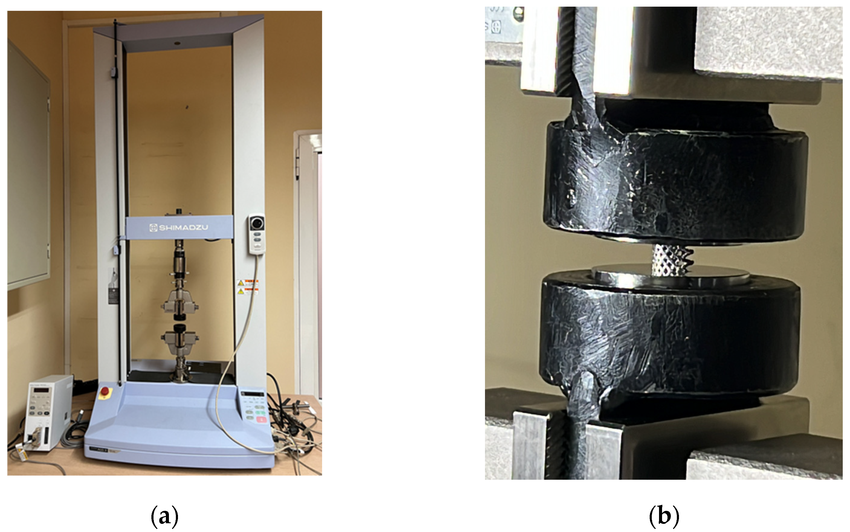
| Brand | Shimadzu |
|---|---|
| Model | Table-top AGS-X 10 kN |
| Weight | 85 kg |
| Power | 1.2 kW |
| Max load/capacity | 10 kN |
| Dimensions | W 653 mm × D 520 mm × H 1603 mm |
| Crosshead speed range | 0.001 to 1000 mm/min |
| Crosshead speed accuracy | 0.1% |
| Crosshead–table distance (tensile stroke) | 1200 mm (760 mm, MWG) |
| Data capture rate | 1000 Hz max |
| # | 1 | 2 | 3 | 4 | 5 | 6 | 7 | 8 | 9 | 10 | 11 | 12 | |
|---|---|---|---|---|---|---|---|---|---|---|---|---|---|
| Speed (mm/min) | F (N) | F (N) | F (N) | F (N) | F (N) | F (N) | F (N) | F (N) | F (N) | F (N) | F (N) | F (N) | |
| 1 | 1 | 37 ↓1 | 5 ↑2 | 42 ↓ | 800 ↓ | 42 ↑ | 1300 ↓ | 42 ↑ | |||||
| 2 | 1 | 37 ↓ | 5 ↑ | 42 ↓ | 5 ↑ | 55 ↓ | 5 ↑ | 150 ↓ | 55 ↑ | 500 ↓ | 150 ↑ | 1300 ↓ | 5 ↑ |
| 3 | 0.25 | 37 ↓ | 5 ↑ | 42 ↓ | 5 ↑ | 55 ↓ | 5 ↑ | 150 ↓ | 55 ↑ | 500 ↓ | 150 ↑ | 1300 ↓ | 5 ↑ |
| dx (mm) | F (N) | E (N/mm2) |
|---|---|---|
| 0.115 | 10 | 1095 1 |
| 0.185 | 37 | 1842 |
| 0.41 | 150 | 6278 |
| 0.6 | 500 | 9738 |
| 0.955 | 1300 | 14010 |
Disclaimer/Publisher’s Note: The statements, opinions and data contained in all publications are solely those of the individual author(s) and contributor(s) and not of MDPI and/or the editor(s). MDPI and/or the editor(s) disclaim responsibility for any injury to people or property resulting from any ideas, methods, instructions or products referred to in the content. |
© 2023 by the authors. Licensee MDPI, Basel, Switzerland. This article is an open access article distributed under the terms and conditions of the Creative Commons Attribution (CC BY) license (https://creativecommons.org/licenses/by/4.0/).
Share and Cite
Stojković, J.R.; Stojković, M.; Turudija, R.; Aranđelović, J.; Marinkovic, D. Adjustable Elasticity of Anatomically Shaped Lattice Bone Scaffold Built by Electron Beam Melting Ti6Al4V Powder. Metals 2023, 13, 1522. https://doi.org/10.3390/met13091522
Stojković JR, Stojković M, Turudija R, Aranđelović J, Marinkovic D. Adjustable Elasticity of Anatomically Shaped Lattice Bone Scaffold Built by Electron Beam Melting Ti6Al4V Powder. Metals. 2023; 13(9):1522. https://doi.org/10.3390/met13091522
Chicago/Turabian StyleStojković, Jelena R., Miloš Stojković, Rajko Turudija, Jovan Aranđelović, and Dragan Marinkovic. 2023. "Adjustable Elasticity of Anatomically Shaped Lattice Bone Scaffold Built by Electron Beam Melting Ti6Al4V Powder" Metals 13, no. 9: 1522. https://doi.org/10.3390/met13091522