
Microstructure and Properties of Nonlinear Lap Joint of 6061 Aluminum Alloy by Friction Stir Welding
1
School of Materials Science and Engineering, Henan University of Science and Technology, Luoyang 471023, China
2
Provincial and Ministerial Co-Construction of Collaborative Innovation Center for Non-ferrous Metal New Materials and Advanced Processing Technology, Luoyang 471023, China
3
School of Mechanical, Materials, and Mechatronics Engineering, Faculty of Engineering and Information Sciences, University of Wollongong, Northfield Ave, Wollongong, NSW 2500, Australia
*
Author to whom correspondence should be addressed.
Metals 2023, 13(8), 1494; https://doi.org/10.3390/met13081494
Submission received: 25 July 2023
/
Revised: 17 August 2023
/
Accepted: 19 August 2023
/
Published: 21 August 2023
Abstract
:The microstructure and properties of non-linear friction stir welded lap joints of the AA6061-T6 aluminum alloy were investigated, with a particular focus on the influence of corner curvature on the formability and mechanical properties of the joints. The research results indicate that for the 6061-T6 aluminum alloy lap joint friction stir welding with a smaller radius (R < 7 mm), there is a more severe accumulation of welding material. When the radius exceeds 7 mm, good macroscopic joint formation can be achieved. Various regions at the joint corners are composed of α-Al and intermetallic precipitations β phases. The microstructure of the heat-affected zone (HAZ) appeared relatively coarse, the weld nugget zone (WNZ) had the finest grain, and partial dissolution of the β phase occurred. The grain size in the middle WNZ at the corner was larger than at the ends, and the grain size on the inner side of the corner was larger than on the outer side. The hardness distribution of the joint exhibited a “W” shape, with the lowest hardness in the inner HAZ. When R ≤ 7, with an increase in R, the shear strength of the friction stir welded joints increased, and then the change became relatively small. The maximum shear strength of the joint was 101.32 ± 6.89 MPa at R = 7, and the fracture mode was primarily a ductile mixed fracture.
1. Introduction
Friction stir welding (FSW) is a solid-state joining process, invented by W. Thomas and E. Nicholas at The Welding Institute (TWI) in Cambridge, United Kingdom, in 1991 [1]. It utilizes a rotating tool to establish material flow and achieve the joining. FSW is largely applicable to aluminum and its alloy, copper, magnesium, composite material, polymers, and some specific ferrous material due to its advantage over conventional welding [2,3]. Among these materials, aluminum alloy is the most common one. Almost all of the aluminum alloys can be joined using FSW. The FSW processes for pure aluminum [4], Al–Li [5,6], Al–Mg [7,8], Al–Mg–Si [9,10], Al–Cu [11,12], Al–Zn [13], and Al–Mn [14,15] aluminum alloys have been widely investigated.
In recent years, AA6061 aluminum alloy (Al-Mg-Si alloy) is the most commonly used in the aviation, maritime, and automotive industries, due to its weight saving, higher strength, good corrosion resistance, and machinability features [16]. The FSW joining process for AA6061 aluminum alloy has also attracted a lot of attention from researchers [17]. The relevant research primarily focuses on the development of novel processes and the relationship between microstructure and mechanical properties. Lee et al. [18] conducted a study on Lap joint FSW between 6061 and 5052 aluminum alloys with varying thicknesses, using different welding parameters. The results revealed that the joint strengths of the FSWed lap joints were primarily influenced by the interface morphology and the vertical transport of each material under different welding conditions. Choudhary et al. [19] investigated different parameters for the FSW of Al 6061. The results indicated an increase in microhardness with the number of passes, as well as a decrease in grain size with the number of weld passes and an increase with rotational speed. Additionally, the presence of hard Al2O3 precipitates was observed. Vysotskiy et al. [20] developed two simple but effective strategies to optimize friction-stir welding of a 6061-T6 alloy. The first strategy optimized welding variables to achieve both a higher welding temperature and a shorter thermal cycle, thereby preventing precipitation coarsening in the heat-affected zone (HAZ) and resulting in exceptional strength under static and cyclic loading conditions. The second strategy involved postweld T6 tempering and prestrain rolling to prevent abnormal grain growth (AGG) during the solutionizing of aluminum friction-stir welds. Elatharasan et al. [21] developed an empirical relationship to estimate the ultimate tensile strength (UTS), yield strength (YS), and tension elongation (TE) of friction stir welded AA 6061-T6 aluminum alloy. The results indicated that the UTS and YS of the FSW joints increased with an increase in tool rotational speed, welding speed, and tool axial force, up to a certain maximum value, after which they decreased. On the other hand, the TE of the joints increased with an increase in rotational speed and axial force, but it decreased with increasing welding speed.
The type of FSW tools and tool tilt angle (TTA) are also significant factors influencing FSW microstructure and performance. Hassanifard et al. [22] conducted a study to investigate the mechanical properties of Al 6061-T6 joints using various FSW tools. They found that the welding tool shape influenced the measured hardness values and grain sizes within the weld regions. Improved tensile properties of the aluminum joint samples were observed with increasing cone angle from 0° to 20° using different welding tools. This improvement was attributed to enhanced plastic flow evolution over the weld zones during welding. However, beyond a cone angle of 20°, the tensile strength and elongation of the joint samples notably decreased. Banik et al. [23] investigated the effect of torque and force on microstructure and mechanical properties of 6 mm thick AA6061 joint due to varying tool design and TTA. The results revealed that with an increase in TTA, the spindle torque and force increased, and it was also reported that there was a decrease in the X-force with the use of a taper threaded tool.
The influence mechanisms of microstructure on the mechanical properties and fatigue behavior of FSW joints have been further extensively studied. Zhang et al. [24] evaluated the microstructural and notch locations on impact and fatigue crack growth (FCG) behavior. The results show that the grain size, hardness, and impact absorbing energy of weld nugget zone (WNZ) was smaller than those of base material (BM) and HAZ. Longitudinal residual stresses dominated all the zones of the joint, FSW-induced compressive stresses in WNZ. The particles in aluminum alloy matrix can impede the propagation of fatigue crack. The microstructural inhomogeneity and crack closure contribute to the fluctuation FCG rate. Kalinenko et al. [25] investigated the relationship between temperature conditions during FSW, stir-zone (SZ) microstructure, and the thermal stability of welded aluminum alloy 6061 joints. The conclusion drawn was that the AGG was governed by at least two mechanisms: the pinning effect exerted by second-phase particles and the enhanced mobility of 40° <111> boundaries. Kalinenko et al. [26] also investigated the microstructure–strength relationship in friction-stir welded 6061-T6 aluminum alloy. The study revealed that weld strength was significantly impacted by precipitation coarsening and particle dissolution. While both of these phenomena led to material softening, the effects of particle dissolution were partially counteracted by the subsequent re-precipitation of solute clusters. Du et al. [27] investigated the correlation between microstructure and the mechanical properties of the 6061-T6 double-side FSW joint. The results showed that the welding of the front-side improved the dislocation density and precipitates in the remaining back-side shoulder affect zone (SAZ), leading to increased hardness. However, this also resulted in a decrease in strength and elongation of the remaining back-side SAZ in the welding direction due to poor combination between the deposited metal layers under thermal and mechanical influences from the welding of the front side.
Recently, with the expansion of the FSW application range and the demand for complex space structure welding in various industrial fields, such as aerospace components and water-cooling equipment, there is a growing need for the development of more flexible FSW equipment and research on the FSW welding process for complex space structures [28]. However, most of the existing research on the FSW process of 6061 aluminum alloy primarily focuses on regular weld seams, and there is still limited research on the process for non-linear joints. Therefore, this study focused on the investigation of non-linear friction stir welding at the junction of a 6061-T6 aluminum alloy, aiming to determine the influence of corner curvature on the microstructure and performance of friction stir welded joints. This work offers a theoretical and experimental foundation for the design and manufacturing of friction stir welding in the connection of complex-shaped aluminum alloy components.
2. Materials and Methods
The experimental materials used in the study were 5 mm thick AA6061-T6 aluminum alloy sheets. The main chemical composition is shown in Table 1, and the mechanical properties are shown in Table 2 [29]. The dimensions of the workpiece to be welded were 80 mm × 80 mm × 5 mm. The stirring tool had a shoulder diameter of 16 mm and a pin length of 6 mm. Prior to friction stir welding, the workpiece surface was treated with alcohol. Figure 1 illustrates the corner lap joint. The process parameters for friction stir welding were as follows: rotation speed: 1000 r/min; welding speed: 150 mm/min; plunge depth: 0.3 mm; tilt angle: 2°; corner radius (R): 1 mm, 4 mm, 7 mm, 10 mm, 13 mm. Except for the corner radius, the other process parameters were determined through linear lap joint experiments in our preliminary work. In this study, we kept the other parameters constant using the control variable method, specifically examining the influence of corner radius on the microstructure and properties of the joints.
The microstructural samples were obtained by cutting across the cross-sectional position of the corner joint, perpendicular to the FSW weld seam, as shown in Figure 1. The samples were then etched using Weck’s reagent (100 mL H2O + 4 g KMNO4 + 1 g NaOH) for 150 s, followed by rinsing in a 25% HNO3 solution for 20 s. Optical microscopy (OM) (Carl Zeiss AG, Jena, Germany) was used to observe the welded joints in different regions, while a scanning electron microscope (SEM) (JSM-IT200, JEOL USA, Inc., Peabody, MA, USA) analyze the interface microstructure and fracture modes.
Tensile specimens were prepared following the guidelines outlined in the standard GT/T2651-2008 [30]. Tensile specimens were cut from the FSWed plate through wire cutting, with the cutting positions indicated in Figure 1. The dimensions of the specimens are presented in Figure 2. Tensile tests were conducted on the prepared specimens using a mechanical testing machine (Shimadzu Corporation, Kyoto, Japan). To ensure the consistency between the joint interface and the tensile direction, equally thick spacer plates were added on both sides of the joint. The tensile speed was set at 1 mm/min. To minimize the impact of random fluctuations, a minimum of three valid tests were performed for each set of identical parameters.
The hardness distribution of the joint was measured using an MHV-2000 microhardness tester (Beijing TIME Shuncheng Technology Co., Ltd., Beijing, China). The test points are illustrated in Figure 2, with hardness tests conducted along the cross-section of the joint at the position of the top plate. The testing points were spaced 0.4 mm apart, and the test load was set at 0.1 kgf with a dwell time of 10 s. The microhardness value was from the average of 5 measurements.
3. Results
3.1. Macro Topography of Joints
Figure 3 shows the macroscopic morphology of lap joints with different corner radii (R). As shown in Figure 3a,b, when the corner radius (R) was less than 7 mm, there was material accumulation at the corner of the weld seam, resulting in an increased thickness of the weld seam. When R ≥ 7 mm, as depicted in Figure 3c–e, no material accumulation was observed at the corner, and the weld seam showed good macroscopic formation at the corner.
In theory, a larger corner radius is more favorable for achieving a well-formed and uniform joint surface. As the corner radius (R) decreased, the dwell time of the stirring tool in the corner area increased per unit area. This prolonged exposure to heat in the corner area led to material accumulation and an increased thickness of the weld seam. Additionally, the high temperature caused the formation of a dense aluminum oxide film on the surface of the weld seam, resulting in the gradual roughening of the corner area of the joint. However, when R > 10 mm, the transitional area at the corner significantly increased, and further increasing R did not hold much significance for precision-forming requirements.
3.2. Microstructure of Joints
Figure 4 illustrates the cross-sectional morphology of the lap joint at the non-linear corner of the 6061-T6 aluminum alloy, obtained by FSWwith a corner radius of R = 7. The connection position in Figure 4 is at the junction of the top and bottom plates of the 6061-T6 aluminum alloy. RS represents the retreating side of the stirring tool, and AS represents the advancing side. Due to the combined action of shoulder pressure and stirring pin, there was sufficient material flow.
Generally, FSWed joints of aluminum alloys can be divided into several regions: the WNZ; the thermo-mechanically affected zone (TMAZ); the HAZ; and the BM, which lies beyond the HAZ [31,32]. The interface zone (IZ) is a special region located within the WNZ, representing the interface where the two plates are joined. These regions were also observed in the cross-section of the 6061-T6 aluminum alloy FSW joints, as depicted in Figure 4. Corroding the joints with an etchant results in different colors in these regions. The WNZ exhibited a darker color, gradually transitioning to brighter hues towards the sides of the parent material, and this differentiation was supplemented with the dimensions of the stirring pin and shoulder of the stirring tool. The joining zone between the top and bottom plates exhibited a wider shape on top and narrowed towards the bottom, forming a “U” shape overall. It should be noted that the microstructure of joint sections with different corner radii was relatively similar. Therefore, in the subsequent analysis, we focused on analyzing the microstructural characteristics of the joint corners using the sample with R = 7 as a representative.
Figure 5 shows the microstructure of various regions on the cross-section of the top plate at the corner of the joint with R = 7 mm. Comparing Figure 5a–e, it can be observed that the grain size decreased sequentially from the BM to the TMAZ and then to the WNZ. This phenomenon has been widely validated in previous literature [33]. As shown in Figure 5b, the WNZ exhibited a fine equiaxed grain structure composed of the α-Al matrix and a small amount of hard intermetallic precipitations (β phase, such as Mg2Si and Mg2Al3) [34]. This region has undergone repeated fragmentation under the action of the stirring tool, resulting in the formation of many regrowth cores and recrystallization, leading to the formation of fine equiaxed grains.
Figure 5a,c represents the TMAZ, where deformation occurred due to frictional heat and mechanical action of the stirring tool. Localized recrystallization took place in this region, and the grains were elongated with a certain directional alignment. The microstructure of the advancing and retreating sides in this zone exhibited a certain degree of symmetry due to the opposite directions of the applied forces. Figure 5d represents the HAZ, which was only affected by the frictional heat transferred from the center of the weld. The high temperature caused grain growth in this region. The microstructure of the HAZ was similar to that of the BM (Figure 5e), but the grains were coarser compared to the BM.
Figure 6 shows the backscattered electron images of the joint area in a 6061-T6 aluminum alloy friction stir weld. In backscattered electron images, different elements’ substances will appear with significant brightness and contrast differences, making it easier to distinguish the α-Al matrix and the β phases. From Figure 6a,b, it can be observed that the BM contained a large number of granular and partially rod-shaped precipitates of metastable β phase (Mg2Si, Mg2Al3). As shown in Figure 6c,d, the HAZ was influenced by the welding thermal cycle. In general, the temperature peak in the HAZ during the FSW process of the 6061 aluminum alloy was around 360–380 °C [35]. The metastable β phase underwent overaging and coarsening.
Figure 6e,f reveals that in the TMAZ, the precipitates mainly consisted of granular and a small amount of irregular polygonal shapes. The density of the precipitates in this zone was much lower than that in the BM and HAZ. This was mainly due to the influence of welding thermal cycles and the squeezing action of the stirring tool.
As shown in Figure 6g,h, the precipitates in the WNZ had a similar shape to those in the TMAZ. There was also a small amount of β phase precipitates distributed on the α-Al matrix. However, the WNZ experienced a greater influence of welding thermal cycles with higher peak temperatures, typically around 450 °C [35]. This higher temperature leads to the partial dissolution of the metastable β phase, resulting in a reduced distribution density [35].
Figure 7 shows the EBSD grain orientation maps and corresponding grain size distribution maps of the inner and outer sides of the corner region in the 6061-T6 aluminum alloy friction stir weld joint. The detection direction was perpendicular to the welding direction. From Figure 7a,b, it can be observed that both the inner and outer sides were composed of uniformly distributed equiaxed grains with a single shape. The statistical analysis of grain size on the inner and outer sides of the corner region indicated that the grain size distribution predominantly ranged between 7 μm and 8 μm, while on the outer side, it was around 6 μm. It was evident that the grain size on the inner side of the corner was slightly larger than that on the outer side. This was because the inner side of the corner received a higher heat input per unit area within the same period of time compared to the outer side, leading to grain growth.
Figure 8 shows the grain structure and size distribution in the WNZ at the corner of the 6061-T6 aluminum alloy FSWjoint. It can be observed that the grains in the corner region, before, middle, and after the corner, were all fine equiaxed grains. The grain size in the middle of the corner was slightly larger than at other positions. Specifically, the grain size on the front side of the corner was mainly in the range of 2–4 μm, the grain size on the middle side of the corner was mainly in the range of 4–6 μm, and the grain size on the rear side of the corner was mainly in the range of 3–4 μm. This was because the heat generated on the front side of the corner was transferred towards the middle position, and the frictional heat generated on the rear side of the corner also spread towards the middle. Compared to the linear joint WNZ, the middle position of the corner experienced higher heat input, leading to grain growth and an increase in grain size.
3.3. Microhardness of Joint
Figure 9 shows the microhardness distribution at the corners of the 6061-T6 aluminum alloy FSWjoint with different R values. From Figure 9, it can be observed that the microhardness distribution perpendicular to the weld direction on the top plate of the joint exhibited a “W” shape. This type of hardness distribution has been reported a number of times in previous literature as well [18]. The hardness in the joint region (about 60–70 HV0.1) was lower than that in the BM region (around 90 HV0.1). Specifically, the hardness points of the WNZ were slightly higher than the hardness in the TMAZ and HAZ regions. The lowest hardness point was observed in the inner side of the corner in the HAZ. This was mainly because the HAZ underwent thermal cycling, resulting in the softening of the matrix. Additionally, the heat input reduced the dislocation density. The inner side of the HAZ experienced higher heat input, larger grain size, and softening of the matrix. In contrast, the WNZ directly experienced the frictional heat, leading to softening of the matrix as well. However, due to the mechanical action of the stirring tool, it also resulted in the formation of more fine-grained structures and a significant increase in dislocation density. Consequently, the hardness of the WNZ differed from that of the HAZ. Overall, with increasing R, the hardness of each region initially increased and then decreased. The sudden increase in hardness in the HAZ can be attributed to the transformation of the β phase from a metastable state to a stable state under heating, accompanied by an increase in size, which occurred at the testing points located on the β phase.
3.4. Mechanical Properties of the Joint
Figure 10 shows the shear strength of AA6061-T6 aluminum alloy friction stir welded joints with different corner radii (R). When R ≤ 7, with an increase in R, the shear strength of the friction stir welded joints increased, and then the change became relatively small. In this study, it is worth noting that the fracture locations of the friction stir welded joints in 6061-T6 aluminum alloy were all located at the junction of the top and bottom plates, regardless of the corner radius. The maximum strength of the friction stir welded joint was achieved when R was 7 mm, reaching 101.32 ± 6.89 MPa, while the joint strength was the lowest when R was 1 mm.
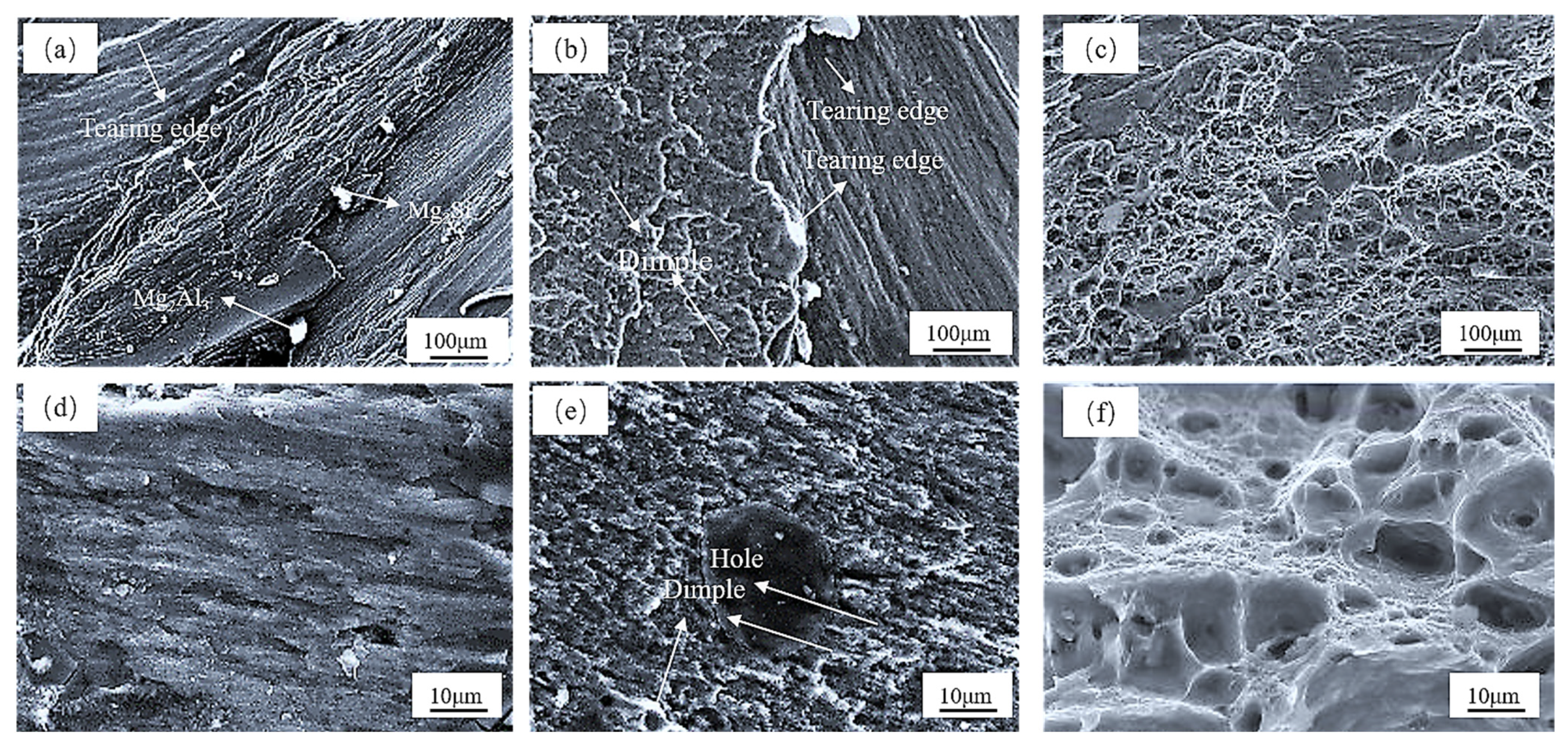
Figure 11 shows the typical tensile fracture surfaces of a 6061-T6 aluminum alloy lap friction stir welded joints with different corner radii. From Figure 11, it can be observed that the fractures of the friction stir welds occurred at the junction of the top and bottom plates of the 6061-T6 aluminum alloy. Figure 11a,d shows the fracture morphology of the friction stir welded joint with R = 1 mm. The fracture surface appeared relatively flat, exhibiting river-like patterns, numerous tearing edges, a few pores, and dimples, indicating significant brittle fracture characteristics. At this corner radius, the friction stir welded joint had not formed a good connection. When R = 4 mm, as shown in Figure 11c,f, the number of tearing edges decreased, while the dimple region increased. The fracture surface of the friction stir welded joint exhibited a mixed fracture pattern, primarily characterized by brittle fracture. When R = 7 mm, as depicted in Figure 11b,e, the fracture surface of the friction stir welded joint contained numerous dimples and a few tearing edges. The dimples were densely distributed with varying sizes, indicating a mixed fracture pattern primarily characterized by ductile fracture. The mixed characteristics of brittle and ductile fractures were also observed by Du et al. [27] in the joints of 6061-T6 double-side friction stir welded joints.
Clearly, as R increases, the fracture mode of the friction stir welded joint changes from brittle fracture to a mixed fracture with a dominant ductile characteristic. There are two main reasons for this transformation. On one hand, when the corner radius is too small, it leads to material accumulation on the inner side, causing uneven deformation between the inner and outer sides, resulting in an uneven stress distribution. On the other hand, this is due to the larger heat input when the corner radius is small, and the excess heat promotes grain growth. These two factors contribute to a decrease in the joint’s performance. As the corner radius increases to above 7 mm, these phenomena are alleviated, and the joint strength stabilizes. In practical manufacturing processes, controlling the corner radius within the range of 7 mm to 10 mm can achieve an ideal friction stir welded joint.
4. Conclusions
- (1)
- For 6061-T6 aluminum alloy lap joint friction stir welding with a smaller radius (R < 7 mm), there is a more severe accumulation of welding material. When the radius exceeds 7 mm, good macroscopic joint formation can be achieved.
- (2)
- The FSWed lap joint of a 6061-T6 aluminum alloy can be divided into four zones: WNZ, THAZ, HAZ, and BM. These zones consist of α-Al and intermetallic precipitation β phases. The HAZ had a coarse microstructure, while the WNZ had a fine microstructure with partial dissolution of the β phases. The grain size in the middle of the WNZ was larger than that at the two ends, and the grain size on the inner side of the corner was larger than that on the outer side.
- (3)
- The hardness distribution of the joint showed a “W” shape. The hardness points of the WNZ were slightly higher than the hardness in the TMAZ and HAZ regions. The lowest hardness point was observed in the inner side of the corner in the HAZ.
- (4)
- When R ≤ 7, with an increase in R, the shear strength of the friction stir welded joints increased, and then the change became relatively small. The maximum shear strength of the joint was 101.32 ± 6.89 MPa at R = 7, and the fracture mode was primarily a ductile mixed fracture.
Author Contributions
Conceptualization, L.Q., N.M., X.X. and K.Z.; methodology L.Q., N.M., X.X. and K.Z.; validation, N.M. and X.X.; formal analysis, N.M. and K.Z.; investigation, L.Q., N.M., X.X. and K.Z.; resources, K.Z.; data curation, L.Q. and N.M.; writing—original draft preparation, L.Q., N.M., X.X. and K.Z.; writing—review and editing, L.Q., N.M. and H.L.; visualization, L.Q. and N.M.; supervision, N.M., X.X. and K.Z.; project administration, N.M. and K.Z. All authors have read and agreed to the published version of the manuscript.
Funding
This work was supported by the Major Project for Science and Technology of Luoyang City, China (Grant No. 2101015A); the Joint Foundation for Science and Technology Research and Development Plan of Henan Province, China (Grant No. 222103810033 and No. 222103810035); and the Frontier Exploration Project of Longmen Laboratory in Henan Province, China (Grant No. LMQYTSKT004).
Institutional Review Board Statement
Not applicable.
Informed Consent Statement
Not applicable.
Data Availability Statement
The data that support the findings of this study are available from the corresponding author upon reasonable request.
Conflicts of Interest
The authors declare no conflict of interest.
References
- Thomas, W.M.; Nicholas, E.D.; Needham, J.C.; Murch, M.G.; Templesmith, P.; Dawes, C.J. Friction Stir Butt Welding. UK Patent No. 9125978.8, 6 December 1991. [Google Scholar]
- Sajed, M.; Guerrero, J.W.G.; Derazkola, H.A. A Literature Survey on Electrical-Current-Assisted Friction Stir Welding. Appl. Sci. 2023, 13, 1563. [Google Scholar] [CrossRef]
- Ahmed, M.M.; El-Sayed Seleman, M.M.; Fydrych, D.; Çam, G. Friction Stir Welding of Aluminum in the Aerospace Industry: The Current Progress and State-of-the-Art Review. Materials 2023, 16, 2971. [Google Scholar] [CrossRef] [PubMed]
- Nagira, T.; Liu, X.; Ushioda, K.; Fujii, H. Microstructural evolutions of 2n grade pure al and 4n grade high-purity Al during friction stir welding. Materials 2021, 14, 3606. [Google Scholar] [CrossRef]
- Shi, L.; Dai, X.; Tian, C.; Wu, C. Effect of splat cooling on microstructures and mechanical properties of friction stir welded 2195 Al–Li alloy. Mat. Sci. Eng. A Struct. 2022, 858, 144169. [Google Scholar] [CrossRef]
- Kumar, S.; Katiyar, J.K.; Kesharwani, G.S.; Roy, B.S. Microstructure, mechanical, and force-torque generation properties of friction stir welded third generation Al/Li alloy at higher traverse speed. Mater. Today Commun. 2023, 35, 106084. [Google Scholar] [CrossRef]
- Ding, T.; Yan, H.; Chen, J.; Xia, W.; Su, B.; Zhu, H. Microstructure Evolution and Recrystallization Mechanisms of High Mg Alloyed Al-Mg Alloy during Friction Stir Welding with Different Cooling Media. J. Mater. Eng. Perform. 2023, 32, 3809–3820. [Google Scholar] [CrossRef]
- Talebizadehsardari, P.; Musharavati, F.; Khan, A.; Sebaey, T.A.; Eyvaziana, A.; Derazkola, H.A. Underwater friction stir welding of Al-Mg alloy: Thermo-mechanical modeling and validation. Mater. Today Commun. 2021, 26, 101965. [Google Scholar] [CrossRef]
- Memon, S.; Murillo-Marrodán, A.; Lankarani, H.M.; Aghajani Derazkola, H. Analysis of friction stir welding tool offset on the bonding and properties of Al–Mg–Si alloy T-joints. Materials 2021, 14, 3604. [Google Scholar] [CrossRef]
- Baghdadi, A.H.; Sajuri, Z.; Omar, M.Z.; Rajabi, A. Friction stir welding parameters: Impact of abnormal grain growth during post-weld heat treatment on mechanical properties of Al–Mg–Si welded joints. Metals 2020, 10, 1607. [Google Scholar] [CrossRef]
- Shankar, S.; Chattopadhyaya, S.; Vilaça, P. Effect of compensating aluminium alloy during friction stir welding of Al-Cu alloys having dissimilar thicknesses. Mater. Today Commun. 2023, 34, 105141. [Google Scholar] [CrossRef]
- Li, D.; Liu, H.; Du, S.; Li, X.; Gao, Y.; Zuo, Y. Investigation on material flow and microstructural evolution mechanism in non-thinning and penetrating friction stir welded Al–Cu aluminum alloy. Mat. Sci. Eng. A Struct. 2023, 864, 144572. [Google Scholar] [CrossRef]
- Chen, Y.; Wang, Y.; Meng, G.; Liu, B.; Wang, J.; Shao, Y.; Jiang, J. Macro-galvanic effect and its influence on corrosion behaviors of friction stir welding joint of 7050-T76 Al alloy. Corros. Sci. 2020, 164, 108360. [Google Scholar] [CrossRef]
- Kasman, Ş.; Sertan, O.Z.A.N. Characterization of friction stir welded AA 3003-H24 aluminum alloy plates. Sigma J. Eng. Nat. Sci. 2022, 40, 620–629. [Google Scholar] [CrossRef]
- Gao, K.; Basak, S.; Mondal, M.; Zhang, S.; Hong, S.T.; Boakye, S.Y.; Cho, H.H. Friction stir welding of AA3003-clad AA6013 thin sheets: Microstructural changes related to tensile properties and fatigue failure mechanism. J. Mater. Res. Technol. 2022, 17, 3221–3233. [Google Scholar] [CrossRef]
- Asmare, A.; Al-Sabur, R.; Messele, E. Experimental investigation of friction stir welding on 6061-t6 aluminum alloy using taguchi-based gra. Metals 2020, 10, 1480. [Google Scholar] [CrossRef]
- Christy, J.V.; Mourad, A.H.I.; Sherif, M.M.; Shivamurthy, B. Review of recent trends in friction stir welding process of aluminum alloys and aluminum metal matrix composites. Trans. Nonferr. Met. Soc. China 2021, 31, 3281–3309. [Google Scholar] [CrossRef]
- Lee, C.Y.; Lee, W.B.; Kim, J.W.; Choi, D.H.; Yeon, Y.M.; Jung, S.B. Lap joint properties of FSWed dissimilar formed 5052 Al and 6061 Al alloys with different thickness. J. Mater. Sci. 2008, 43, 3296–3304. [Google Scholar] [CrossRef]
- Choudhary, S.; Choudhary, S.; Vaish, S.; Upadhyay, A.K.; Singla, A.; Singh, Y. Effect of welding parameters on microstructure and mechanical properties of friction stir welded Al 6061 aluminum alloy joints. Mater. Today Proc. 2020, 25, 563–569. [Google Scholar] [CrossRef]
- Vysotskiy, I.V.; Malopheyev, S.S.; Mironov, S.Y.; Kaibyshev, R.O. Optimization of friction-stir welding of 6061-T6 aluminum alloy. Phys. Mesomech. 2020, 23, 402–429. [Google Scholar] [CrossRef]
- Elatharasan, G.; Kumar, V.S. An experimental analysis and optimization of process parameter on friction stir welding of AA 6061-T6 aluminum alloy using RSM. Proc. Eng. 2013, 64, 1227–1234. [Google Scholar] [CrossRef]
- Hassanifard, S.; Ghiasvand, A.; Hashemi, S.M.; Varvani-Farahani, A. The effect of the friction stir welding tool shape on tensile properties of welded Al 6061-T6 joints. Mater. Today Commun. 2022, 31, 103457. [Google Scholar] [CrossRef]
- Banik, A.; Roy, B.S.; Barma, J.D.; Saha, S.C. An experimental investigation of torque and force generation for varying tool tilt angles and their effects on microstructure and mechanical properties: Friction stir welding of AA 6061-T6. J. Manuf. Process. 2018, 31, 395–404. [Google Scholar] [CrossRef]
- Zhang, L.; Zhong, H.; Li, S.; Zhao, H.; Chen, J.; Qi, L. Microstructure, mechanical properties and fatigue crack growth behavior of friction stir welded joint of 6061-T6 aluminum alloy. Int. J. Fatigue 2020, 135, 105556. [Google Scholar] [CrossRef]
- Kalinenko, A.; Kim, K.; Vysotskiy, I.; Zuiko, I.; Malopheyev, S.; Mironov, S.; Kaibyshev, R. Microstructure-strength relationship in friction-stir welded 6061-T6 aluminum alloy. Mat. Sci. Eng. A Struct. 2020, 793, 139858. [Google Scholar] [CrossRef]
- Kalinenko, A.; Mishin, V.; Shishov, I.; Malopheyev, S.; Zuiko, I.; Novikov, V.; Mironov, S.; Kaibyshev, R.; Semiatin, S.L. Mechanisms of abnormal grain growth in friction-stir-welded aluminum alloy 6061-T6. Mater. Charact. 2022, 194, 112473. [Google Scholar] [CrossRef]
- Du, C.; Wang, X.; Pan, Q.; Xue, K.; Ni, M.; Liu, J. Correlation between microstructure and mechanical properties of 6061-T6 double-side FSW joint. J. Manuf. Process. 2019, 38, 122–134. [Google Scholar] [CrossRef]
- Xiao, X.; Mao, Y.; Wang, X.; Qin, D.; Fu, L. Effects of curvature direction on friction stir welding lap joint of aluminum alloy “S” curved surface. Int. J. Adv. Manuf. Technol. 2023, 125, 4693–4705. [Google Scholar] [CrossRef]
- Rajakumar, S.; Muralidharan, C.; Balasubramanian, V. Establishing empirical relationships to predict grain size and tensile strength of friction stir welded AA 6061-T6 aluminium alloy joints. Trans. Nonferrous Met. Soc. China 2010, 20, 1863–1872. [Google Scholar] [CrossRef]
- GB/T2651-2008; Tensile Test Method on Welded Joints. Standardization Administration: Beijing, China, 2008.
- Zolghadr, P.; Akbari, M.; Asadi, P. Formation of thermo-mechanically affected zone in friction stir welding. Mater. Res. Express 2019, 6, 086558. [Google Scholar] [CrossRef]
- Zhang, C.; Huang, G.; Cao, Y.; Zhu, Y.; Li, W.; Wang, X.; Liu, Q. Microstructure and mechanical properties of dissimilar friction stir welded AA2024-7075 joints: Influence of joining material direction. Mat. Sci. Eng. A Struct. 2019, 766, 138368. [Google Scholar] [CrossRef]
- Du, C.; Pan, Q.; Chen, S.; Tian, S. Effect of rolling on the microstructure and mechanical properties of 6061-T6 DS-FSW plate. Mat. Sci. Eng. A Struct. 2020, 772, 138692. [Google Scholar] [CrossRef]
- Maisonnette, D.; Suery, M.; Nelias, D.; Chaudet, P.; Epicier, T. Effects of heat treatments on the microstructure and mechanical properties of a 6061 aluminium alloy. Mat. Sci. Eng. A Struct. 2011, 528, 2718–2724. [Google Scholar] [CrossRef]
- Imam, M.; Biswas, K.; Racherla, V. On use of weld zone temperatures for online monitoring of weld quality in friction stir welding of naturally aged aluminium alloys. Mater. Des. 2013, 52, 730–739. [Google Scholar] [CrossRef]
Figure 1.
Schematic diagram of corner lapping joint.

Figure 2.
Schematic diagram of tensile sample.
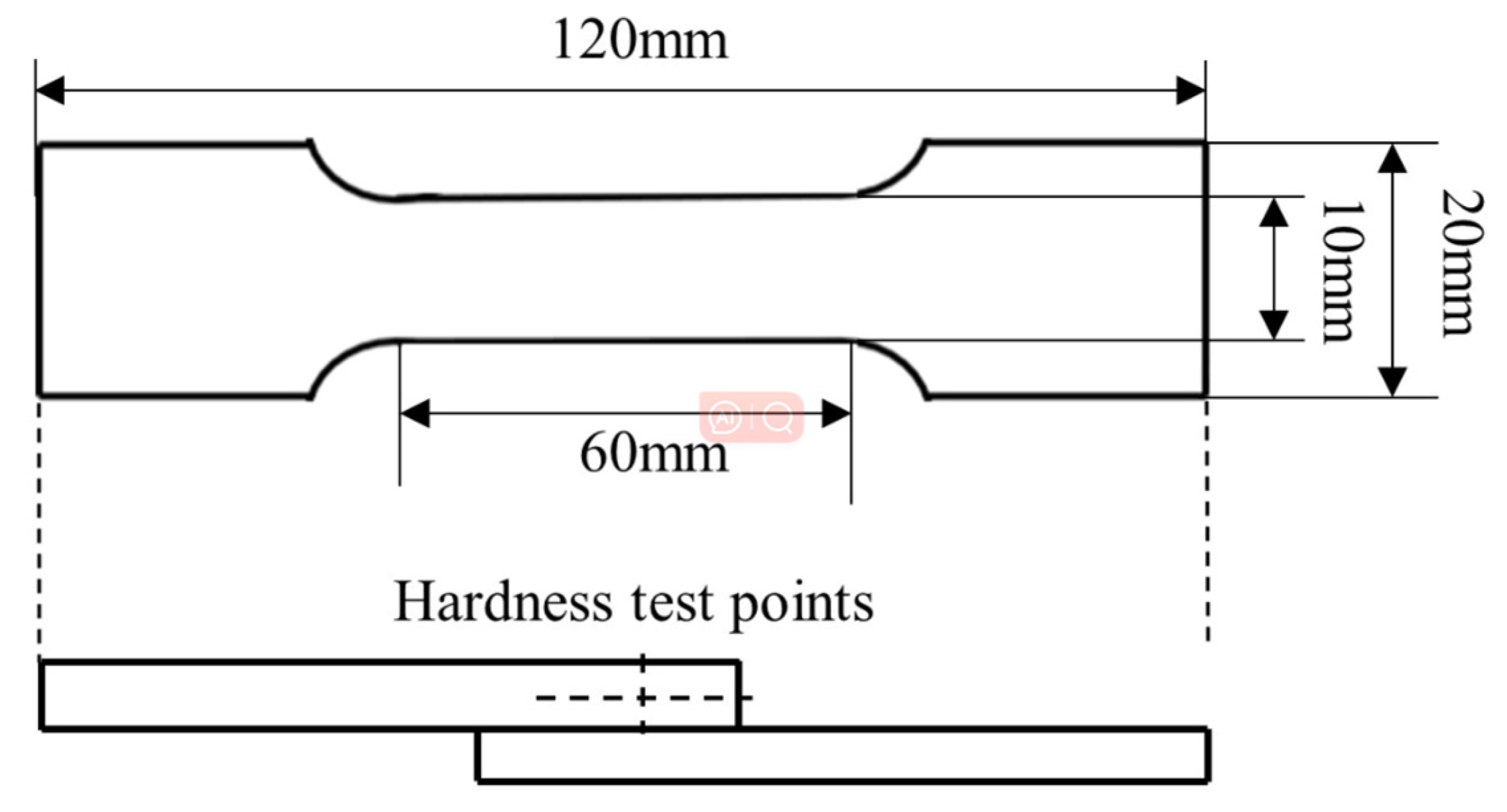
Figure 3.
Joint macroscopic morphology at different R: (a) R = 1 mm; (b) R = 4 mm; (c) R = 7 mm; (d) R = 10 mm; (e) R = 13 mm.
Figure 3.
Joint macroscopic morphology at different R: (a) R = 1 mm; (b) R = 4 mm; (c) R = 7 mm; (d) R = 10 mm; (e) R = 13 mm.
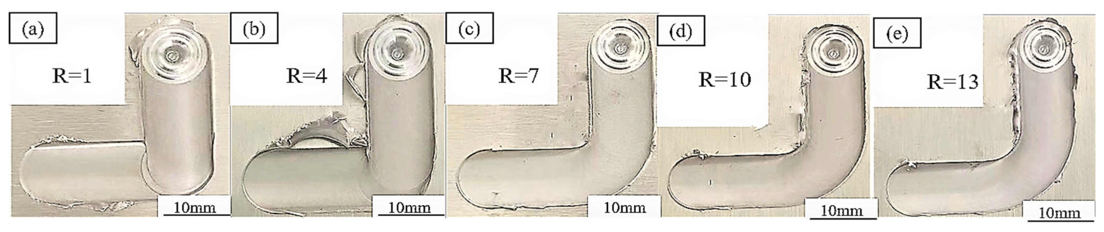
Figure 4.
Joint cross-section morphology when R = 7 mm.
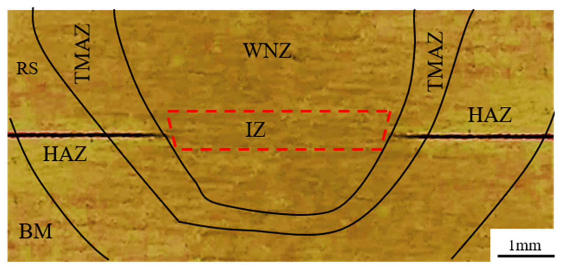
Figure 5.
Microstructure of each region of the top plate of the joint (R = 7 mm): (a) RS-TMAZ; (b) WNZ; (c) AS-TMAZ; (d) HAZ; (e) BM.
Figure 5.
Microstructure of each region of the top plate of the joint (R = 7 mm): (a) RS-TMAZ; (b) WNZ; (c) AS-TMAZ; (d) HAZ; (e) BM.

Figure 6.
Precipitation phase distribution in different regions (R = 7 mm): (a,b) BM; (c,d) HAZ; (e,f) TMAZ; (g,h) WNZ. (b), (d), (f), (h) is an enlarged view of the red area in Figure (a), (c), (e), (g), respectively.
Figure 6.
Precipitation phase distribution in different regions (R = 7 mm): (a,b) BM; (c,d) HAZ; (e,f) TMAZ; (g,h) WNZ. (b), (d), (f), (h) is an enlarged view of the red area in Figure (a), (c), (e), (g), respectively.
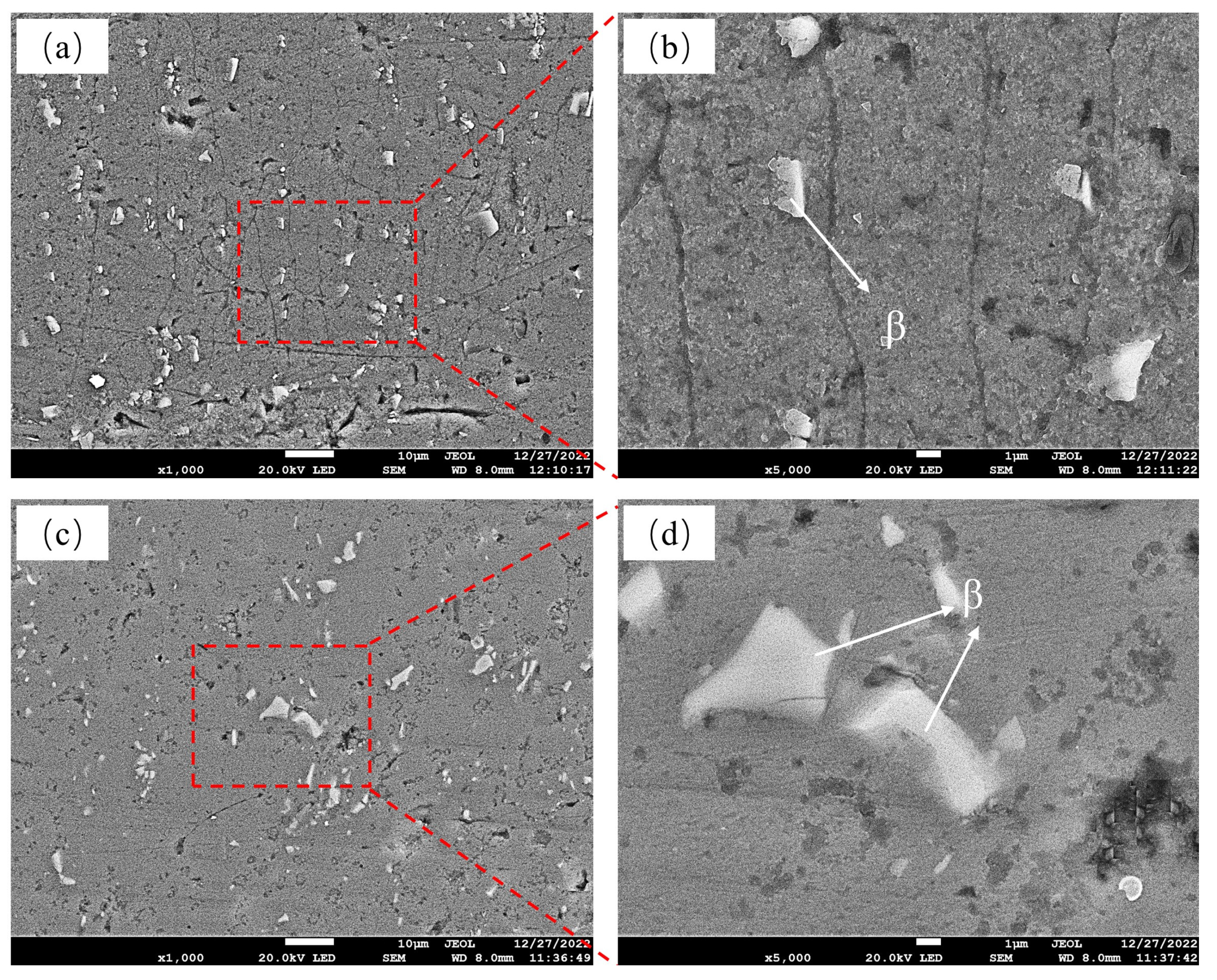
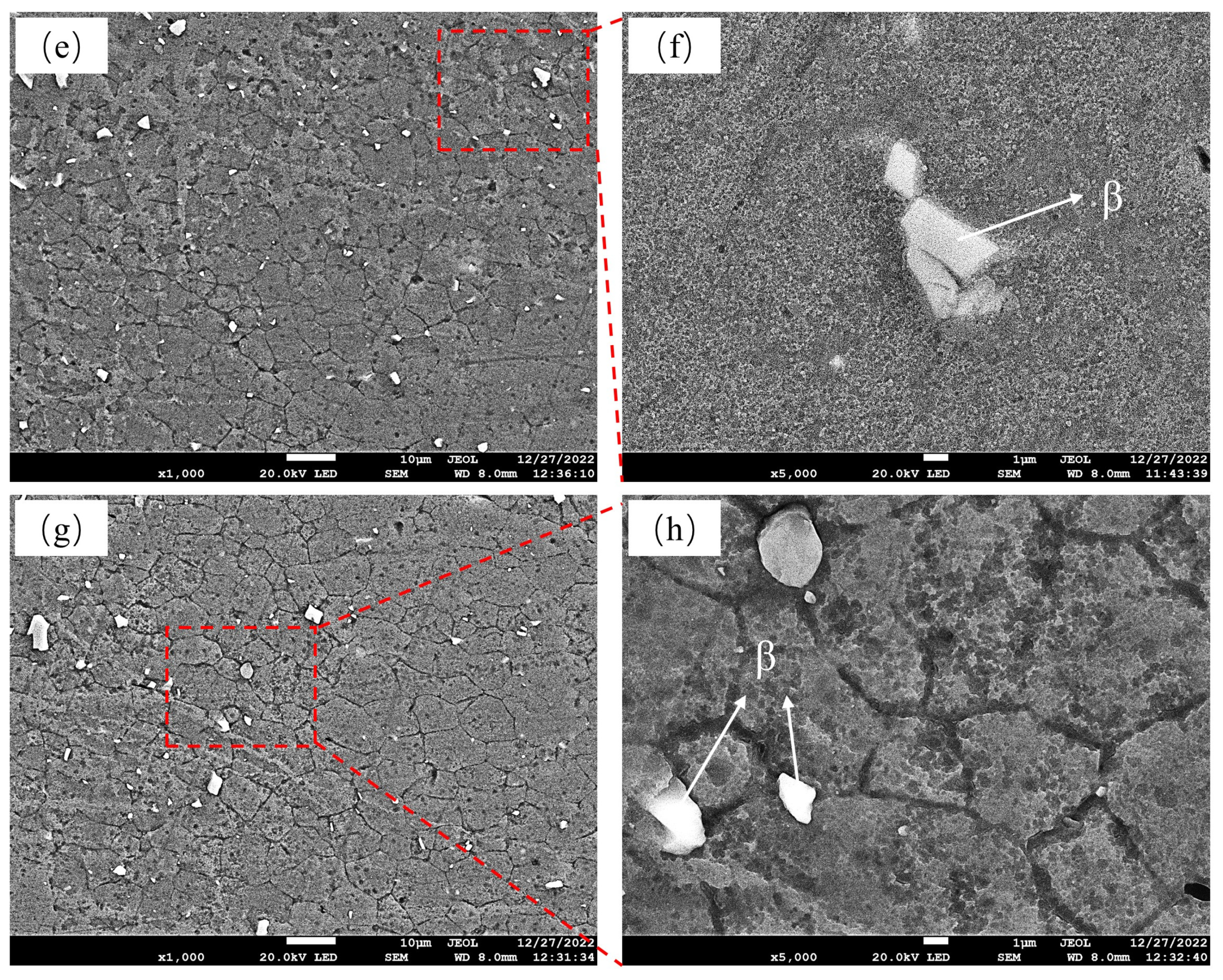
Figure 7.
Grain structure and size distribution inside and outside the corner joint (R = 7 mm). (a) Grain size distribution inside the corner; (b) grain size distribution outside the corner. The blue color represents the <111> crystal orientation, the red color represents the <001> crystal orientation, and the green color represents the <101> crystal orientation.
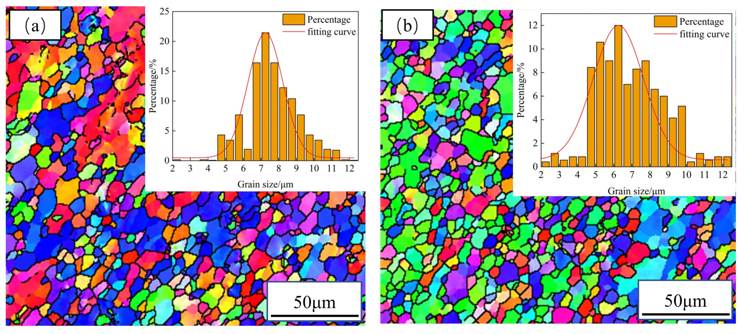
Figure 8.
The schematic diagram of the sampling positions (a) and the EBSD images at the entering corner (b), middle of corner (c), and exiting corner (d) locations. The blue color represents the <111> crystal orientation, the red color represents the <001> crystal orientation, and the green color represents the <101> crystal orientation.
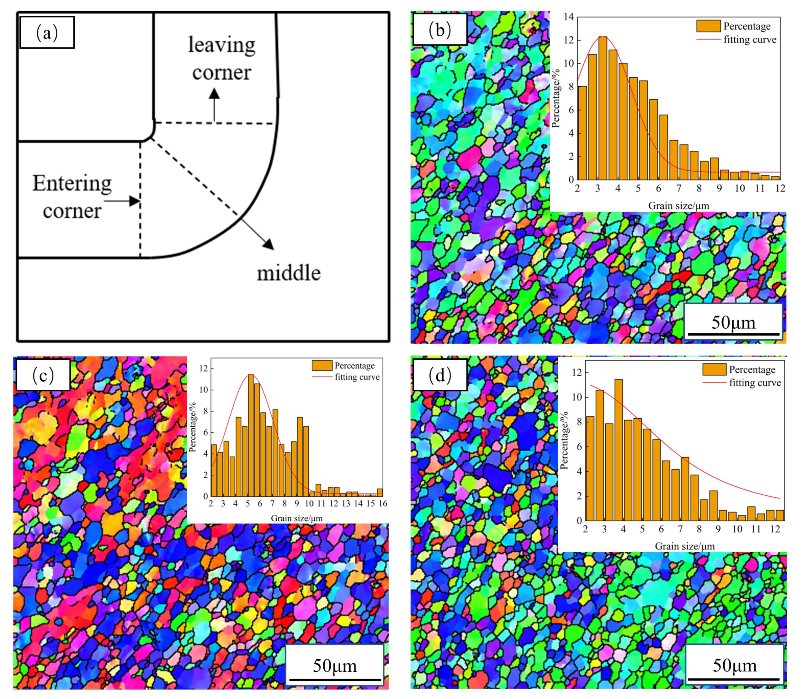
Figure 9.
Microhardness distribution under different R.
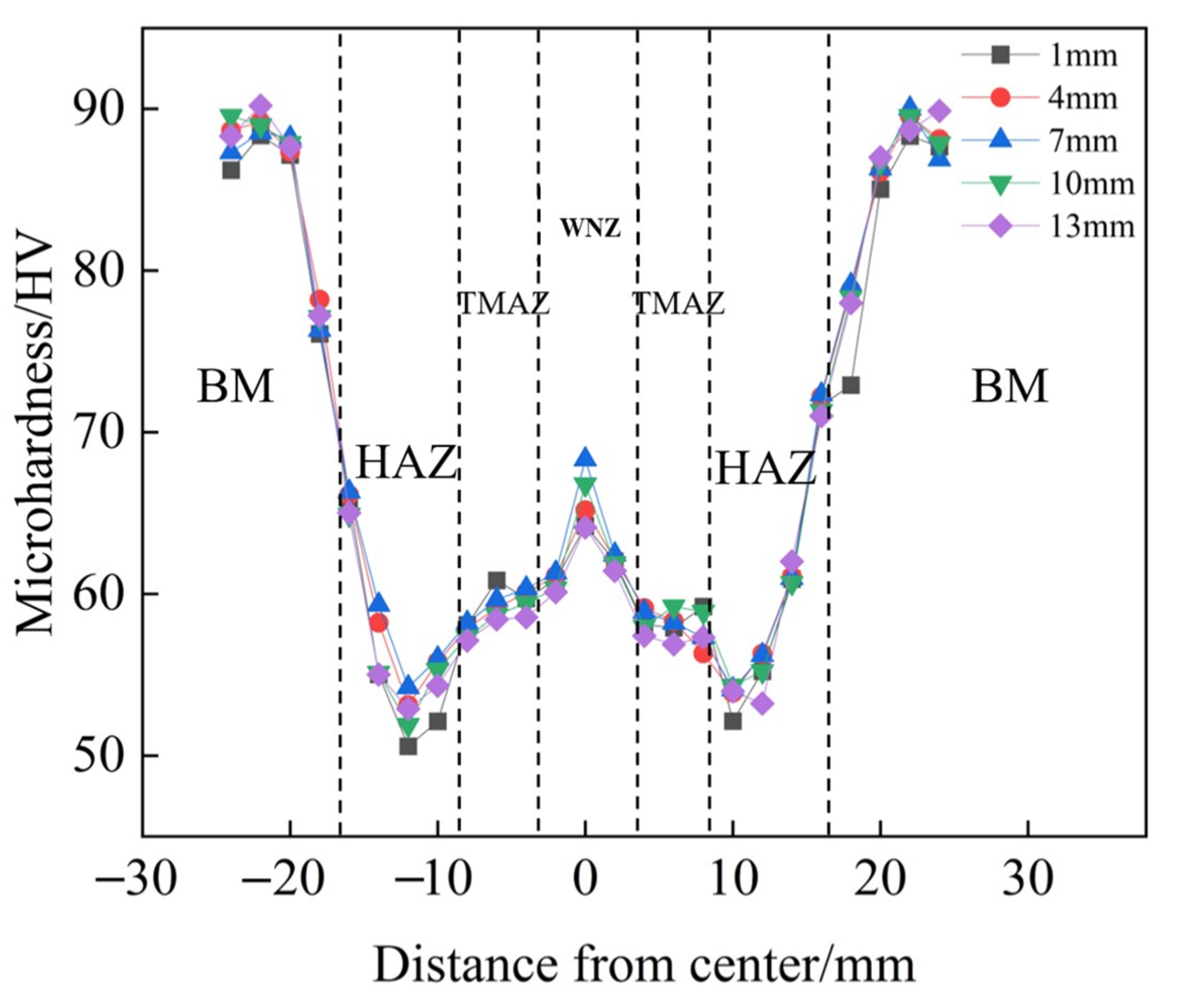
Figure 10.
Shear strength of joints at different R.
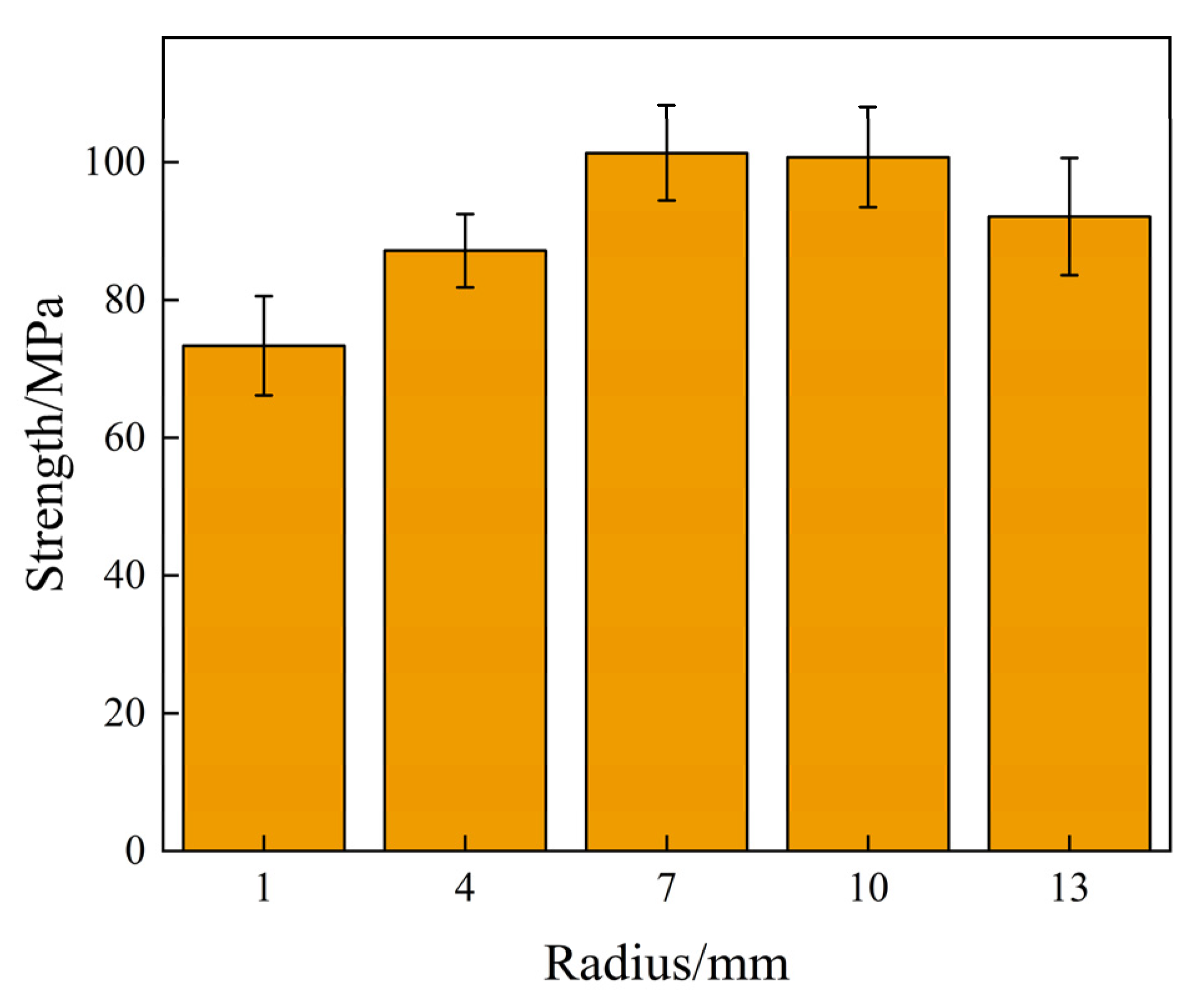
Figure 11.
SEM fractographs of samples at R = 1 mm (a,d), R = 4 mm (b,e), and R = 7 mm (c,f).

Table 1.
Chemical composition of 6061-T6 aluminum alloy (%).
| Mg | Si | Mn | Fe | Cr | Zn | Cu | Ti | Al |
|---|---|---|---|---|---|---|---|---|
| 1.1 | 0.58 | 0.12 | 0.35 | 0.22 | 0.01 | 0.28 | 0.019 | Bal |
Table 2.
Mechanical properties of 6061-T6 aluminum alloy [29].
Table 2.
Mechanical properties of 6061-T6 aluminum alloy [29].
| Material | Yield Strength (MPa) | Tensile Strength (MPa) | Microhardness (HV0.49N) | Elongation (%) |
|---|---|---|---|---|
| 6061-T6 | 235 | 283 | 105 | 26.4 |
Disclaimer/Publisher’s Note: The statements, opinions and data contained in all publications are solely those of the individual author(s) and contributor(s) and not of MDPI and/or the editor(s). MDPI and/or the editor(s) disclaim responsibility for any injury to people or property resulting from any ideas, methods, instructions or products referred to in the content. |
© 2023 by the authors. Licensee MDPI, Basel, Switzerland. This article is an open access article distributed under the terms and conditions of the Creative Commons Attribution (CC BY) license (https://creativecommons.org/licenses/by/4.0/).
Share and Cite
MDPI and ACS Style
Qu, L.; Ma, N.; Xiao, X.; Zhang, K.; Li, H. Microstructure and Properties of Nonlinear Lap Joint of 6061 Aluminum Alloy by Friction Stir Welding. Metals 2023, 13, 1494. https://doi.org/10.3390/met13081494
AMA Style
Qu L, Ma N, Xiao X, Zhang K, Li H. Microstructure and Properties of Nonlinear Lap Joint of 6061 Aluminum Alloy by Friction Stir Welding. Metals. 2023; 13(8):1494. https://doi.org/10.3390/met13081494
Chicago/Turabian StyleQu, Laipeng, Ning Ma, Xiao Xiao, Keke Zhang, and Huijun Li. 2023. "Microstructure and Properties of Nonlinear Lap Joint of 6061 Aluminum Alloy by Friction Stir Welding" Metals 13, no. 8: 1494. https://doi.org/10.3390/met13081494
Note that from the first issue of 2016, this journal uses article numbers instead of page numbers. See further details here.