
Influence of Different Filler Metals on the Mechanical and Microstructural Characteristics of Arc-Welded Joints Made of Dissimilar Titanium Alloys
 , and
, and
Abstract
:1. Introduction
- -
- ER Ti-5: wire presenting the chemical composition of Ti6Al4V alloy (Grade 5) belonging to the family with α + ß microstructure;
- -
- ER Ti 9: wire presenting the chemical composition of Ti3Al2V alloy (Grade 9) belonging to the family with near-α microstructure. This alloy exhibits the same ligands as the previous one but with half the percentages.
2. Materials and Methods
2.1. Samples
- Annealed, for α alloy Ti-KS 1.2 ASN-EX;
- Solution treated for α + β alloy Ti6Al4V.
2.2. Welding Procedures
2.3. Types of Analyses
3. Results
3.1. Tensile Test Results
3.2. Bend Test Results
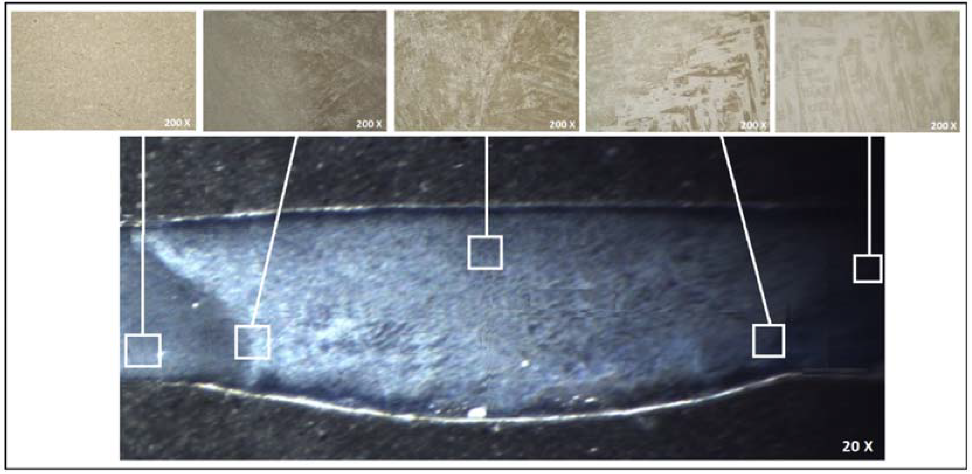
3.3. Micrographic Examinations
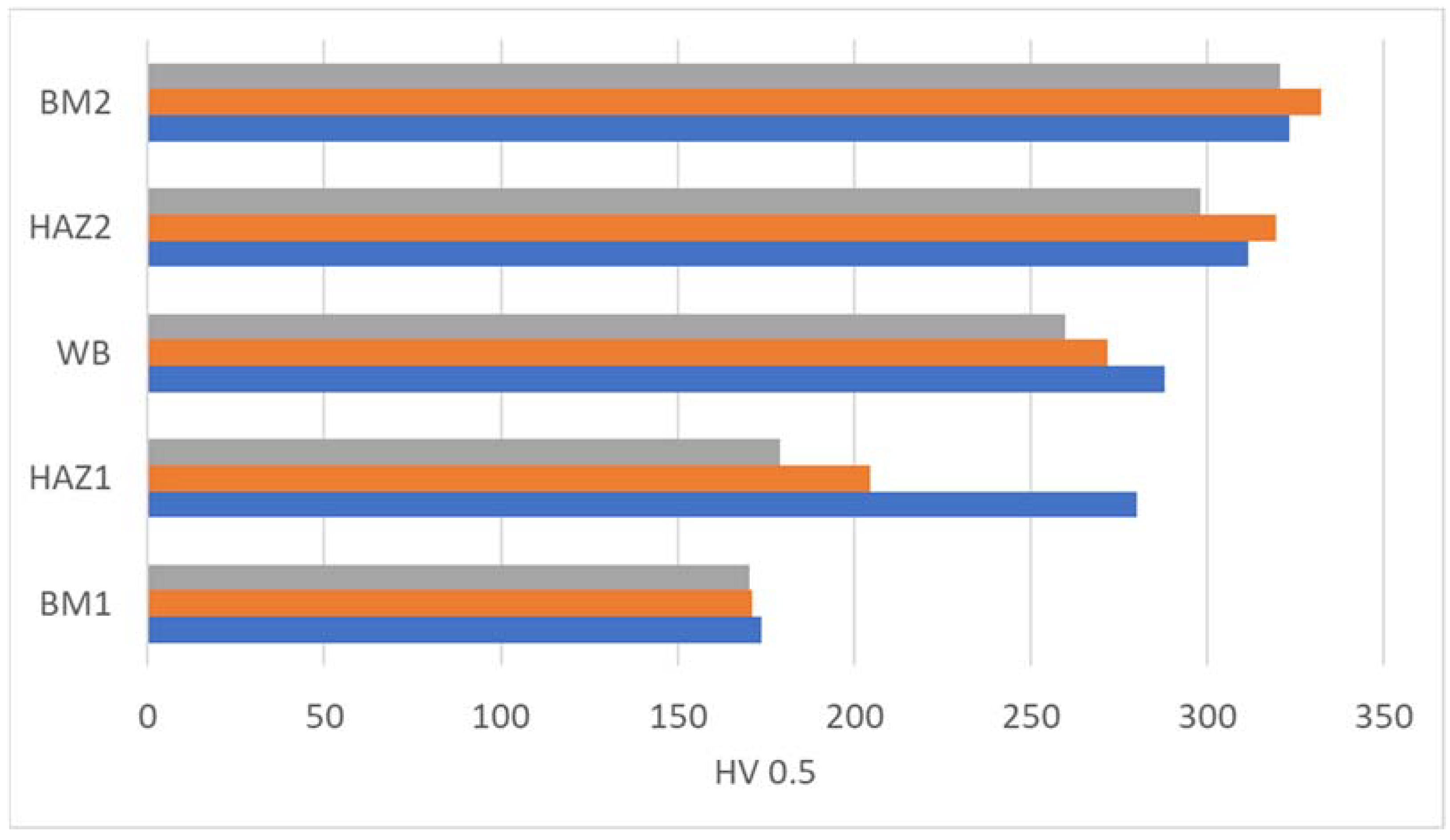
3.4. Microhardness Test Results
3.4.1. Conventional Microhardness Method on Weld Joints
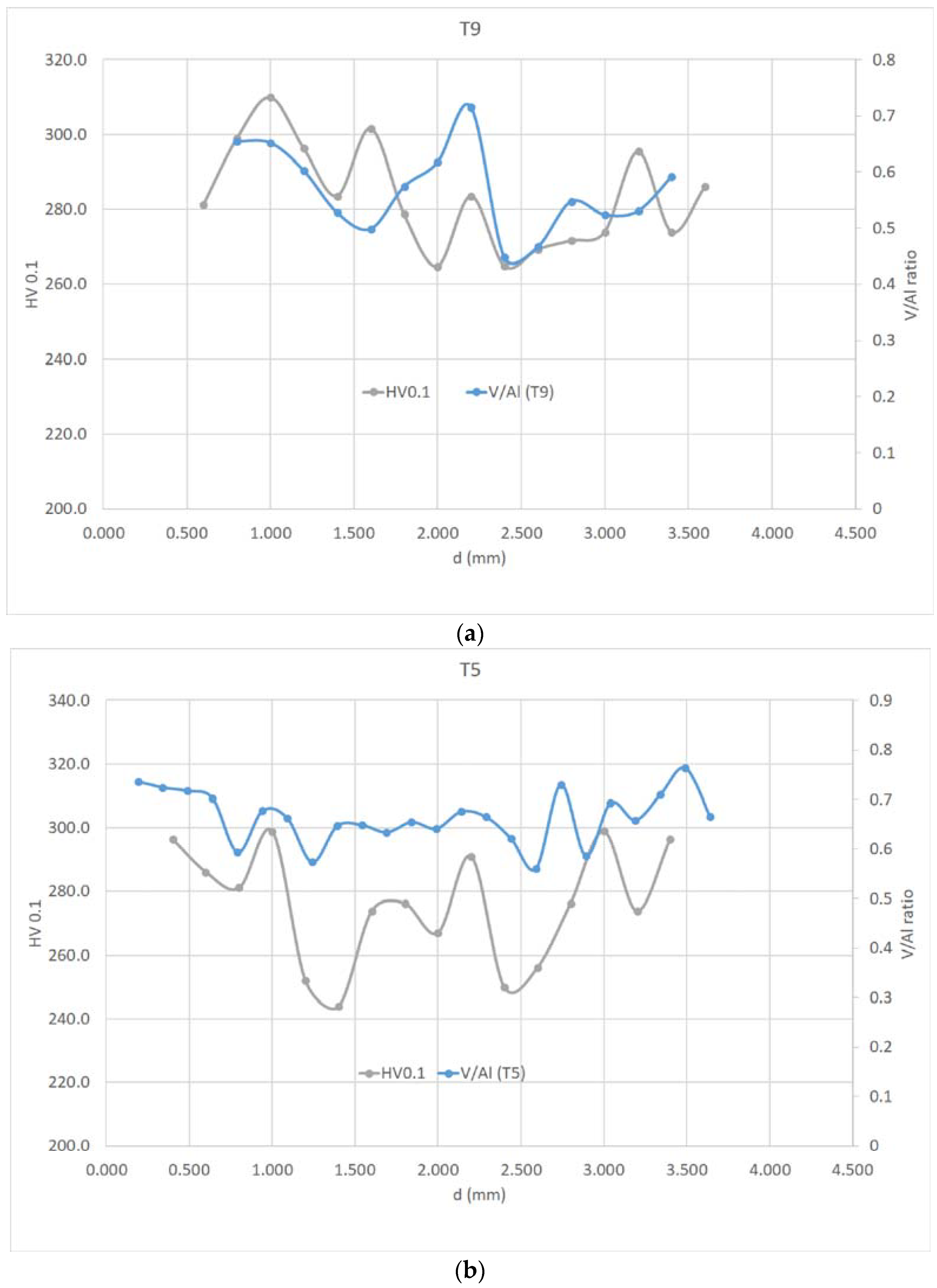
3.4.2. Two-Dimensional Grid Examination
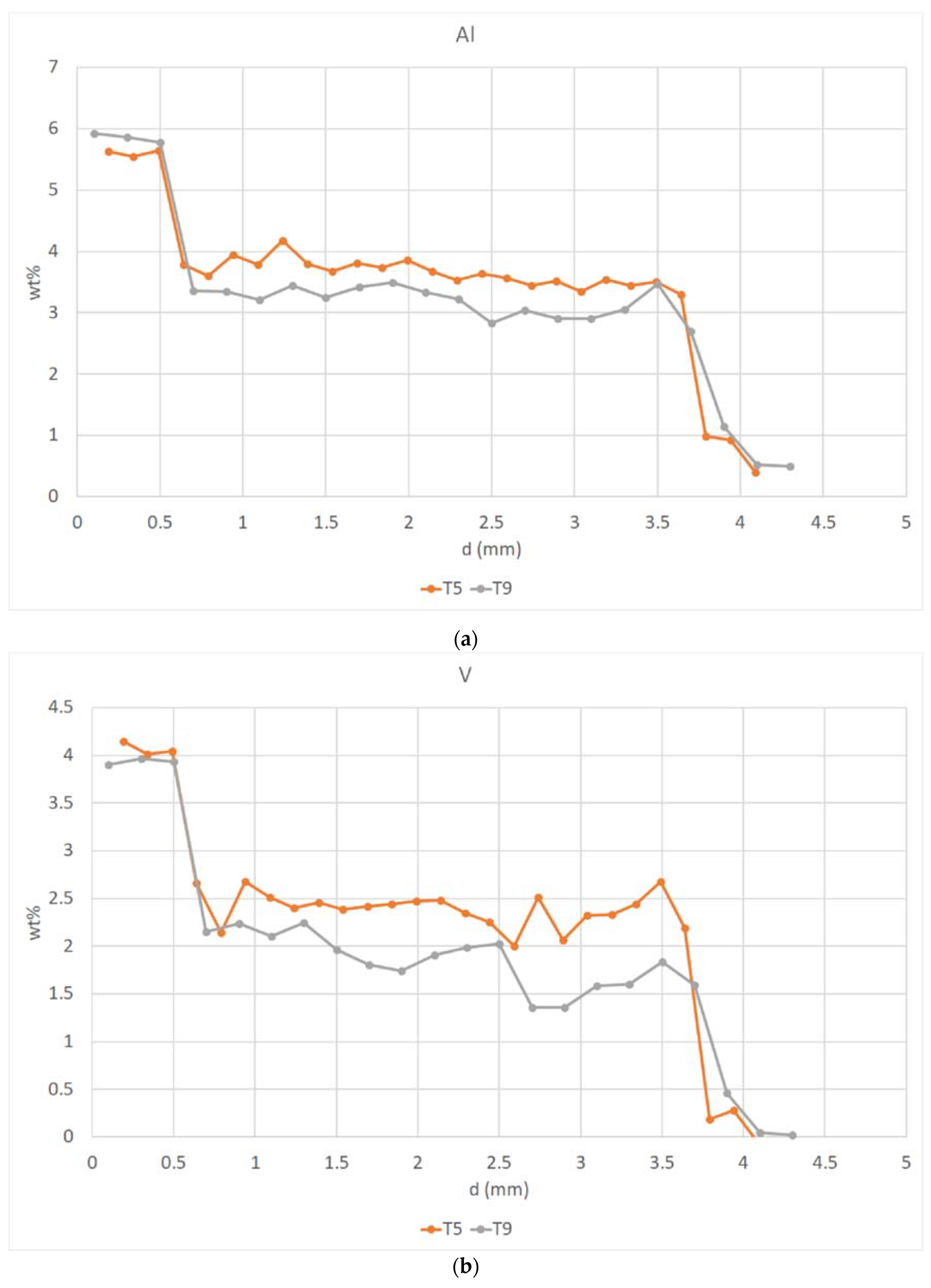
3.5. EDS Profiles
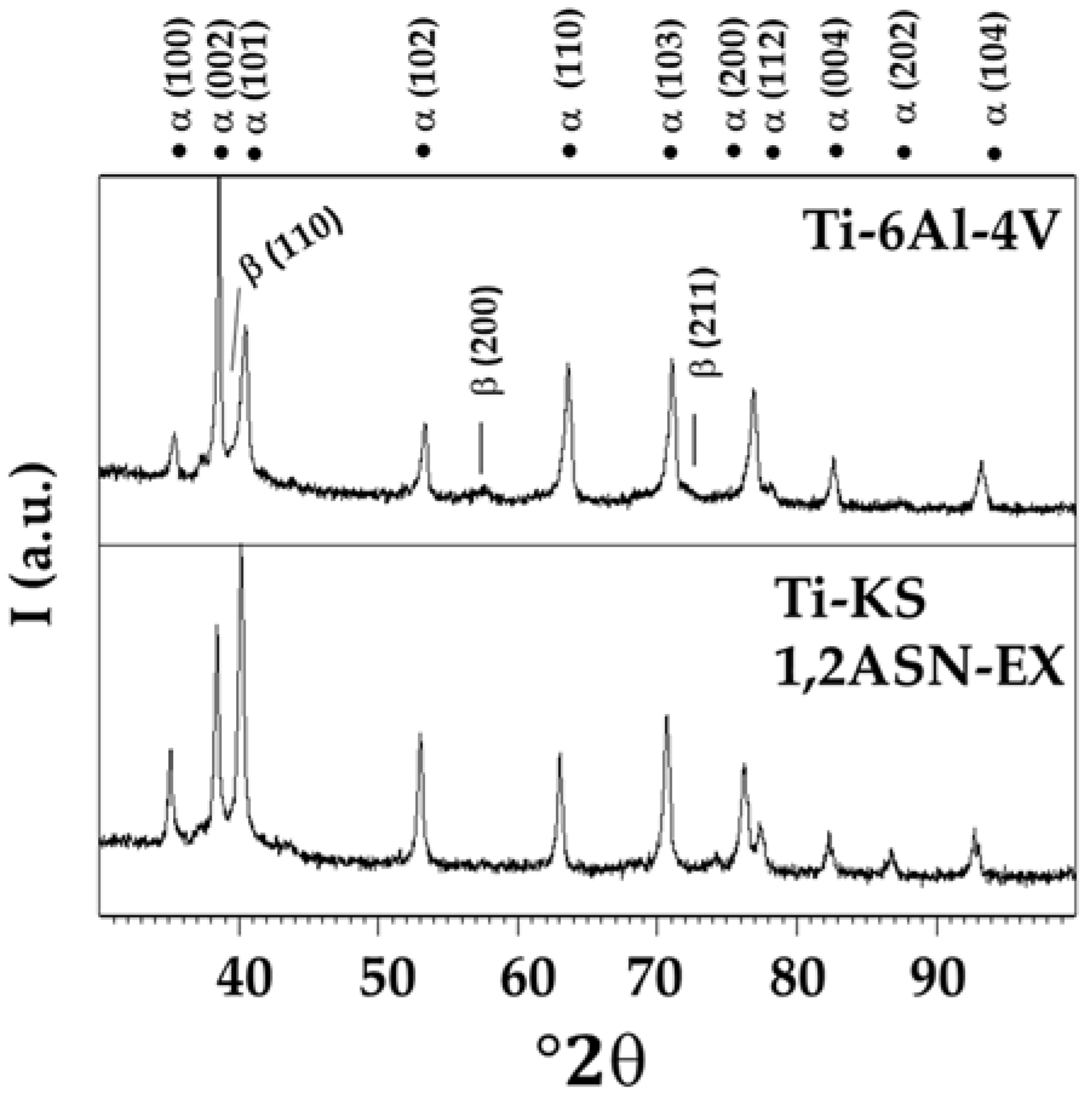
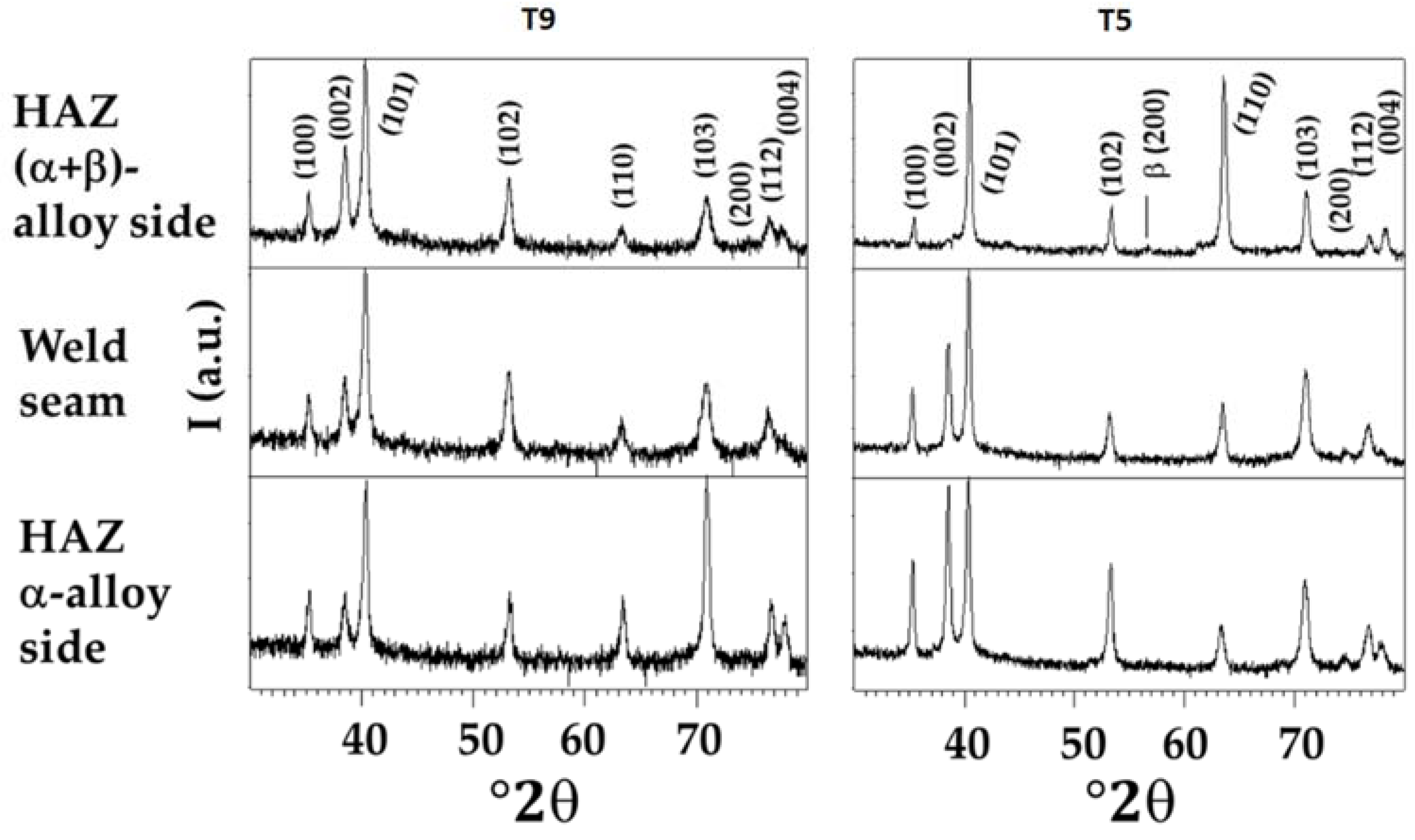
3.6. XRD Analysis
3.7. General Discussion
4. Conclusions
Author Contributions
Funding
Data Availability Statement
Conflicts of Interest
References
- Blanch, O.L.; Pope, J.; Violatos, I.; Rahimi, S.; Jackson, M. Residual Stress Distributions in Dissimilar Titanium Alloy Diffusion Bonds Produced from Powder Using Field-Assisted Sintering Technology (FAST-DB). Met. Mater. Trans. A 2023, 54, 3578–3593. [Google Scholar] [CrossRef]
- Rae, W.; Lomas, Z.; Jackson, M.; Rahimi, S. Measurements of residual stress and microstructural evolution in electron beam welded Ti-6Al-4V using multiple techniques. Mater. Charact. 2017, 132, 10–19. [Google Scholar] [CrossRef]
- McAndrew, A.R.; Colegrove, P.A.; Bühr, C.; Flipo, B.C.; Vairis, A. A literature review of Ti-6Al-4V linear friction welding. Prog. Mater. Sci. 2018, 92, 225–257. [Google Scholar] [CrossRef]
- Rajan, S.; Wanjara, P.; Gholipour, J.; Kabir, A.S. Joining of Dissimilar Alloys Ti-6Al-4V and Ti-6Al-2Sn-4Zr-2Mo-0.1Si Using Linear Friction Welding. Materials 2020, 13, 3664. [Google Scholar] [CrossRef] [PubMed]
- Esmaily, M.; Nooshin Mortazavi, S.; Todehfalah, P.; Rashidi, M. Microstructural characterization and formation of α′martensite phase in Ti–6Al–4V alloy butt joints produced by friction stir and gas tungsten arc welding processes. Mater. Des. 2013, 47, 143–150. [Google Scholar] [CrossRef]
- Braga, D.F.; Eslami, S.; Moreira, P. Friction Stir Welding. In Advanced Joining Processes; Elsevier: Amsterdam, The Netherlands, 2021; pp. 173–206. [Google Scholar] [CrossRef]
- Medvedev, A.; Mendes, A.; Lapovok, R.; Semiatin, S. Shear-induced, solid-state joining of Ti-6Al-4V and Ti17 titanium alloys. Mater. Sci. Eng. A 2018, 737, 253–264. [Google Scholar] [CrossRef]
- Du, S.; Liu, H.; Gao, Y.; Hu, Y.; Zhou, L. Effects of process parameters on joint formation and tool wear behavior in friction stir welded TA5 alloy. Int. J. Adv. Manuf. Technol. 2022, 123, 2531–2547. [Google Scholar] [CrossRef]
- Amirov, A.; Chumaevskii, A.; Savchenko, N.; Gurianov, D.; Nikolaeva, A.; Krasnoveykin, V.; Ivanov, A.; Rubtsov, V.; Kolubaev, E. Features of Permanent Joints of Titanium (α + β)-Alloys Obtained by Friction Stir Welding Using a Nickel Superalloy Tool. Metals 2023, 13, 222. [Google Scholar] [CrossRef]
- Tarasov, S.; Amirov, A.; Chumaevskiy, A.; Savchenko, N.; Rubtsov, V.E.; Ivanov, A.; Moskvichev, E.; Kolubaev, E. Friction Stir Welding of Ti-6Al-4V Using a Liquid-Cooled Nickel Superalloy Tool. Technologies 2022, 10, 118. [Google Scholar] [CrossRef]
- Chumaevskii, A.; Amirov, A.; Ivanov, A.; Rubtsov, V.; Kolubaev, E. Friction Stir Welding/Processing of Various Metals with Working Tools of Different Materials and Its Peculiarities for Titanium Alloys: A Review. Metals 2023, 13, 970. [Google Scholar] [CrossRef]
- Li, L.; Sun, L.; Li, M. Diffusion bonding of dissimilar titanium alloys via surface nanocrystallization treatment. J. Mater. Res. Technol. 2022, 17, 1274–1288. [Google Scholar] [CrossRef]
- Pope, J.J.; Calvert, E.L.; Weston, N.S.; Jackson, M. FAST-DB: A novel solid-state approach for diffusion bonding dissimilar titanium alloy powders for next generation critical components. J. Mater. Process. Technol. 2019, 269, 200–207. [Google Scholar] [CrossRef]
- Gietzelt, T.; Toth, V.; Huell, A. Joining Technologies; IntechOpen: London, UK, 2016; Chapter 9; pp. 195–216. [Google Scholar] [CrossRef]
- Farrokhi, A. Welding Properties of Titanium Alloys Grade 5. In Titanium Alloys—Recent Progress in Design, Processing, Characterization, and Applications; IntechOpen: London, UK, 2023. [Google Scholar] [CrossRef]
- Veronesi, P.; Balestri, A.; Colombini, E. Improvement in Wear Resistance of Grade 37 Titanium by Microwave Plasma Oxy-Carburizing. Technologies 2023, 11, 13. [Google Scholar] [CrossRef]
- Raja, V.B.; Palanikumar, K.; Kannan, S.; Sonawwanay, P.D.; Sahas, S.; Muralidharan, S. Influence of welding parameters on mechanical and corrosion properties of Ti6Al4V alloy. Mater. Today Proc. 2023. [Google Scholar] [CrossRef]
- Mehdi, B.; Badji, R.; Ji, V.; Allili, B.; Bradai, D.; Deschaux-Beaume, F.; Soulié, F. Microstructure and residual stresses in Ti-6Al-4V alloy pulsed and unpulsed TIG welds. J. Mater. Process. Technol. 2016, 231, 441–448. [Google Scholar] [CrossRef]
- Sundaresan, S.; Ram, G.J.; Reddy, G.M. Microstructural refinement of weld fusion zones in α–β titanium alloys using pulsed current welding. Mater. Sci. Eng. A 1999, 262, 88–100. [Google Scholar] [CrossRef]
- Mi, G.; Wei, Y.; Zhan, X.; Gu, C.; Yu, F. A coupled thermal and metallurgical model for welding simulation of Ti–6Al–4V alloy. J. Mater. Process. Technol. 2014, 214, 2434–2443. [Google Scholar] [CrossRef]
- American Welding Society (AWS). Specification for Titanium and Titanium-Alloy Welding Electrodes and Rods, 6th ed.; American Welding Society: Doral, FL, USA, 2013. [Google Scholar]
- ISO 15614-1:2017; Specification and Qualification of Welding Procedures for Metallic Materials–Welding Procedure Test—Part 1: Arc and Gas Welding of Steels and Arc Welding of Nickel and Nickel Alloys. International Organization for Standardization: Geneva, Switzerland, 2022.
- ISO 6892-1:2020; Metallic Materials—Tensile Testing–Part 1: Method of Test at Room Temperature. International Organization for Standardization: Geneva, Switzerland, 2020.
- ISO 4136:2022; Destructive Tests on Welds in Metallic Materials—Transverse Tensile Test. International Organization for Standardization: Geneva, Switzerland, 2022.
- ISO 5173:2023; Destructive Tests on Welds in Metallic Materials—Bend Tests. International Organization for Standardization: Geneva, Switzerland, 2023.
- ISO 6507-1:2018; Metallic Materials—Vickers Hardness Test—Part 1–4: Test Method. International Organization for Standardization: Geneva, Switzerland, 2018.
- ASTM E190-21; Standard Test Method for Guided Bend Test for Ductility of Welds. ASTM International: West Conshohocken, PA, USA, 2021.
- Wysocki, B.; Maj, P.; Sitek, R.; Buhagiar, J.; Kurzydłowski, K.J.; Święszkowski, W. Laser and electron beam additive manufacturing methods of fabricating titanium bone implants. Appl. Sci. 2017, 7, 657. [Google Scholar] [CrossRef]
- Oh, J.-M.; Lee, B.-G.; Cho, S.-W.; Lee, S.-W.; Choi, G.-S.; Lim, J.-W. Oxygen effects on the mechanical properties and lattice strain of Ti and Ti-6Al-4V. Met. Mater. Int. 2011, 17, 733–736. [Google Scholar] [CrossRef]
- Cho, J. Characterization of the α′-Martensite Phase and Its Decomposition in Ti-6Al-4V Additively Manufactured by Se-lective Laser Melting. Ph.D. Thesis, RMIT University, Melbourne, Australia, 2018. [Google Scholar]
- Charles, C. Microstructure Model for Ti-6Al-4V used in Simulation of Additive Manufacturing. Ph.D. Thesis, Lulea University of Technology, Lulea, Sweden, 2016. [Google Scholar]


| Material | Al (%) | V (%) | Si (%) | Nb (%) | C (%) | Fe (%) | O (%) | H (%) | N (%) | Ti |
|---|---|---|---|---|---|---|---|---|---|---|
| Ti6Al4V | 6.30 | 4.31 | -- | -- | 0.010 | 0.010 | 0.112 | 0.004 | 0.011 | Bal. |
| Ti-KS 1.2ASN-EX | 0.53 | -- | 0.41 | 0.21 | 0.032 | 0.113 | 0.098 | 0.007 | 0.013 | Bal. |
| ER Ti-5 | 6.28 | 4.14 | -- | -- | 0.024 | 0.157 | 0.130 | -- | 0.008 | Bal. |
| ER Ti-9 | 3.04 | 2.50 | -- | -- | 0.010 | 0.187 | 0.074 | 0.002 | 0.003 | Bal. |
| Sample | Base Material 1 (BM2) | Base Material 2 (BM1) | Filler Metal |
|---|---|---|---|
| T9 | Ti6Al4V | KS 1.2 ASN-EX | ER Ti-9 |
| T5 | Ti6Al4V | KS 1.2 ASN-EX | ER Ti-5 |
| Sample | Rp0.2 MPa | UTS (MPa) | Elong. (%) | Break Area |
|---|---|---|---|---|
| T9 | 292.0 ± 9.9 | 418.5 ± 10.5 | 11.7 ± 0.3 | BM1 (ASN side) |
| T5 | 302.7 ± 6.9 | 429.7 ± 5.3 | 13.2 ± 0.2 | BM1 (ASN side) |
| Sample | Specimen | Specimen Orientation | Bending Angle | Test Results |
|---|---|---|---|---|
| T9 | 1 | Root | 180° | No defects |
| 2 | Root | 180° | No defects | |
| 3 | Face | 180° | No defects | |
| 4 | Face | 180° | No defects | |
| T5 | 1 | Root | 180° | No defects |
| 2 | Root | 180° | No defects | |
| 3 | Face | 180° | No defects | |
| 4 | Face | 180° | No defects |
| Position | c/a Ratio |
|---|---|
| Ti6Al4V | 1.59306 ± 0.00042 |
| Ti-KS 1,2 ASN-Ex | 1.58693 ± 0.00021 |
| T9-weld bead | 1.59175 ± 0.00058 |
| T9_HAZ grade 5 side | 1.59057 ± 0.00049 |
| T9_HAZ_ASN side | 1.59261 ± 0.00052 |
| T5-weld bead | 1.59089 ± 0.00037 |
| T5_HAZ grade 5 side | 1.59777 ± 0.00047 |
| T5_HAZ_ASN side | 1.59087 ± 0.00044 |
Disclaimer/Publisher’s Note: The statements, opinions and data contained in all publications are solely those of the individual author(s) and contributor(s) and not of MDPI and/or the editor(s). MDPI and/or the editor(s) disclaim responsibility for any injury to people or property resulting from any ideas, methods, instructions or products referred to in the content. |
© 2023 by the authors. Licensee MDPI, Basel, Switzerland. This article is an open access article distributed under the terms and conditions of the Creative Commons Attribution (CC BY) license (https://creativecommons.org/licenses/by/4.0/).
Share and Cite
Gaiani, S.; Gozzi, M.; Ferrari, E.; Menozzi, A.; Lassinantti Gualtieri, M.; Colombini, E.; Veronesi, P. Influence of Different Filler Metals on the Mechanical and Microstructural Characteristics of Arc-Welded Joints Made of Dissimilar Titanium Alloys. Metals 2023, 13, 1482. https://doi.org/10.3390/met13081482
Gaiani S, Gozzi M, Ferrari E, Menozzi A, Lassinantti Gualtieri M, Colombini E, Veronesi P. Influence of Different Filler Metals on the Mechanical and Microstructural Characteristics of Arc-Welded Joints Made of Dissimilar Titanium Alloys. Metals. 2023; 13(8):1482. https://doi.org/10.3390/met13081482
Chicago/Turabian StyleGaiani, Silvia, Marica Gozzi, Elisa Ferrari, Alberto Menozzi, Magdalena Lassinantti Gualtieri, Elena Colombini, and Paolo Veronesi. 2023. "Influence of Different Filler Metals on the Mechanical and Microstructural Characteristics of Arc-Welded Joints Made of Dissimilar Titanium Alloys" Metals 13, no. 8: 1482. https://doi.org/10.3390/met13081482