Article

Microstructure Evolution and Growth of Interfacial Intermetallic Compounds in NiCr/Ti Alloy Laminated Composite after Explosive Welding and Heat Treatment

by
Artem Igorevich Bogdanov
*,
Vitaliy Pavlovich Kulevich
and
Victor Georgievich Shmorgun
Materials Science and Composite Materials Department, Volgograd State Technical University, 400005 Volgograd, Russia
*
Author to whom correspondence should be addressed.
Metals 2023, 13(8), 1417; https://doi.org/10.3390/met13081417
Submission received: 30 June 2023 / Revised: 31 July 2023 / Accepted: 4 August 2023 / Published: 8 August 2023

Abstract

:
The paper considers the issues of interaction of the molten metal at the interface of explosively welded NiCr/titanium alloy laminated composites with the reaction zone formed during heat treatment, as well as the features of its destruction after welding. It was established that the molten metal is a heterogeneous mixture based on Ni(Cr,Ti) and Ti(Ni,Al) solid solutions and NiTi and Ni3Ti intermetallic compounds. The estimated existence time of molten metal areas in the liquid state was ~10−8–10−11 s. The obtained values are comparable with the time of the unloading wave arrival at the contact surface, which is the reason for the presence of fracture areas in the form of detachments on the fracture surface. Continuous nanometer-size interlayers with an amorphous structure, due to the ultra-high cooling rate of the liquid melt, induce viscous destruction of the interface. Heat treatment at temperatures of 700 and 850 °C led to the formation of a layered reaction zone at the NiCr/Ti boundary, consisting of interlayers of solid solutions based on Ti2Ni, TiNi, and TiNi3 intermetallic compounds, as well as inclusions of a Cr(Ti) solid solution. The diffusion flow gradient was predominantly directed into the titanium alloy.

1. Introduction

The most important advantage of laminated composite materials is that compositions with an optimal set of service characteristics can be developed for specific operating conditions. A variety of such materials are Metallic–Intermetallic Laminate (MIL) composites [1,2,3,4,5,6]. They combine the special physical properties of intermetallic compounds with the high plasticity of metals and their solid solutions.
The following existing technological processes for obtaining MIL composites have found industrial application. Pressure welding (pack rolling) [7,8,9,10] or explosive welding (EW) [11,12,13,14]) of thin metal sheets with similar resistance to deformation, is followed by diffusion annealing of the layered metal composite. The use of pressure welding makes it possible at the first stage to obtain ductile multilayer metal composites that can be subjected to pressure treatment without micro- and macro-damage in order to give the semi-finished products the required shape and size. At the second stage, subsequent diffusion annealing leads, as a result of reactive diffusion, to the formation of layers based on intermetallic compounds while maintaining a certain thickness of metal layers, providing the necessary margin of plasticity and crack resistance. At the same time, the thicknesses and dimensions of the MIL composite are not particularly limited.
MIL composite fabrication by the diffusion welding method involves hot pressing of a package of alternating foils in a narrow temperature range (near the liquidus point of the most fusible metal) [15,16,17]. The shaping of the workpiece occurs simultaneously with the formation of the intermetallic structure, and a further change in the MIL composite configuration is practically impossible.
To fabricate MIL composite, magnetron layer-by-layer deposition of metal layers followed by diffusion annealing can be also used [18,19]. Magnetron deposition makes it possible to fabricate laminated composites of relatively small dimensions with a layer thickness of several tens or hundreds of micrometers.
Thus, the possibility of obtaining MIL composites of the required shape and size is provided only by explosive welding. The development of explosive welding processes for the design of materials with a laminated structure and the evaluation of their properties were considered in [20,21,22,23,24]. The pioneers in the development of technological processes for the production of layered metal and intermetallic composites by explosive welding are the scientists of the Volgograd State Technical University. Trykov Y.P. et al. [25,26] showed that the ability to pressure treat explosively welded joints without micro- and macroscopic damage could be realized if the areas of local molten metal at the interlayer boundary occupy no more than 10% of the welded joint area. Local inclusions of melted metal are formed if the parameters of the welding mode differ from the optimal ones, which are not always possible to maintain due to the narrowness of their limits. Therefore, areas of local molten metal are always present at the interlayer boundaries of explosively welded joints [27]. Brittle intermetallic compounds, which are part of molten metal areas, reduce the strength of joints when exposed to uniaxial and biaxial tensile stresses [26]. Moreover, the form of intermetallic inclusions plays a significant role in tension. With the same relative length, the rounded shape contributes to destruction mainly along the joint boundary at relatively high values of strength and specific work of destruction, and the elongated needle-like shape, which contributes to an increase in stress concentration, leads to brittle transcrystalline fractures.
It is known [28,29,30,31] that the formation of layers based on intermetallic compounds in MIL composites begins with the formation of local regions (nuclei), which, with an increase in temperature and diffusion annealing time, increase in size and coalesce into a continuous diffusion zone. The formation of nuclei is observed in those areas of the metal interface where the metal has undergone the most intense deformation during welding without local melting. Therefore, the study of the interaction of the molten metal areas formed after welding with the reaction zone formed during heat treatment of a multilayer composite is of both scientific and practical interest.
In this paper, we consider the influence of molten metal at the interlayer boundary of explosively welded Cr20Ni80 and OT4 alloy joints on the features of composite fracture after welding, as well as their interaction with the reaction zone formed during heat treatment of a composite. The choice of Cr20Ni80 and OT4 alloys as the basis for creating the NiCr/Ti MIL system was due to the following reasons: their good explosive weldability, similar strain resistance values, and unique properties of these alloys at normal and elevated temperatures [32,33].

2. Materials and Methods

The NiCr /Ti Alloy composite was produced by explosive welding according to the parallel scheme (Figure 1). A nickel–chromium alloy (Nichrome Cr20Ni80, JSC KUZOCM, Kamensk-Uralsky, Russia) 300 × 200 × 2 mm cladding plate and titanium alloy (OT4, PSC VSMPO-AVISMA Corporation, Moscow, Russia) 300 × 200 × 2 mm base plate, were used in the present study. The chemical composition of the initial materials is presented in Table 1 and Table 2.
The bonding surfaces were finished with 800-grit SiC paper. Before explosive welding, these surfaces were degreased in acetone. Ammonite 6GV with a detonation velocity of 2300 m/s was used as the explosive material. The EW modes are given in Table 3. The collision point velocity (Vc) was chosen based on the condition Vc = 0.3 − 0.8C0, where C0 is the speed of sound in the joined metals. The impact velocity was calculated according to the formula:
V i = 2 W 2 ρ 1 δ 1 + ρ 2 δ 2 ρ 1 ρ 2 δ 1 δ 2 1 V c 2 C 0 2
where ρ1δ1, ρ2δ2—density and thickness of welded metal plates and W2—the specific kinetic energy.
The calculated parameters were experimentally refined to obtain a high-quality welded joint. Further details on the welding technology are presented in [34].
Heat treatment was performed in an SNOL 8.2/1100 electric furnace in the air at 700 and 850 °C. The lower limit corresponds to the maximum temperature, not exceeding the temperature of the eutectoid transformation in the Ti-Ni system, and the upper limit corresponds to the temperature above the eutectoid, but not exceeding the temperature of the titanium polymorphic transformation. The exposure time was up to 100 h. The boundary of the welded joint was not subjected to oxidation during heat treatment, which made it possible to evaluate the kinetics of the diffusion processes at the NiCr/Ti interface. In real conditions, protective coatings or vacuum furnaces can be used to prevent oxidation of the composite.
To study the early stages of diffusion interaction and determine the direction of predominant mass transfer at the interface of the explosively welded composition of the NiCr/Ti system, the samples were heated directly in the column of a Versa 3D electron microscope at the temperature of the most intense diffusion (850 °C) in an Ar medium (in situ).
In order to perform the microstructure observation and chemical analysis using SEM, the cross-sections of the samples were polished using abrasive papers and then mirror-finished using a diamond slurry with a particle size of 0.5 μm.
A Bruker D8 Advance X-ray diffractometer (Bruker AXS GmbH, Karlsruhe, Germany), using CuKα radiation (λ = 0.15406 nm), was used to identify the intermetallic phases. To obtain the XRD patterns of the reaction zones, the NiCr layer was mechanically removed by grinding and finally etched in concentrated nitric acid. The XRD patterns from the surface of fractures were obtained directly from the surface of the NiCr or OT4 alloy after peel strength tests of the explosively welded samples.
The surface morphologies and cross-sectional microstructures of samples were observed by scanning electron microscopy (SEM–Versa 3D, Thermo Fisher Scientific Inc., Hillsboro, OR, USA) in conjunction with energy dispersive X-ray spectroscopy (EDS- EDAX Trident XM 4, EDAX, Inc., Mahwah, NJ, USA). The thickness and relative length of the molten metal was determined by analyzing the microstructures using the AnalySIS Pro 3·2 software (Soft Imaging System GmbH, Münster, Germany).
Peel strength tests of the welded joint were performed using the Lloyd LR5K+ testing system (Lloyd Instruments Ltd., Bognor Regis, UK).

3. Results and Discussion

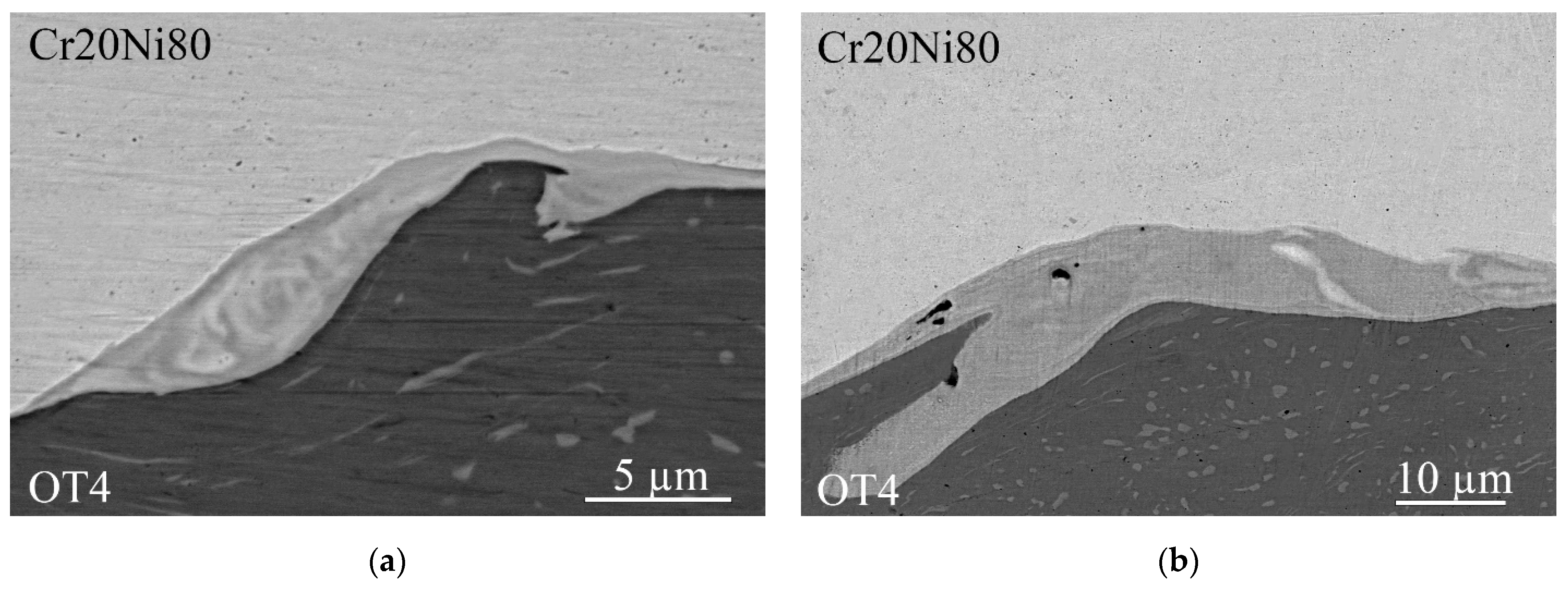
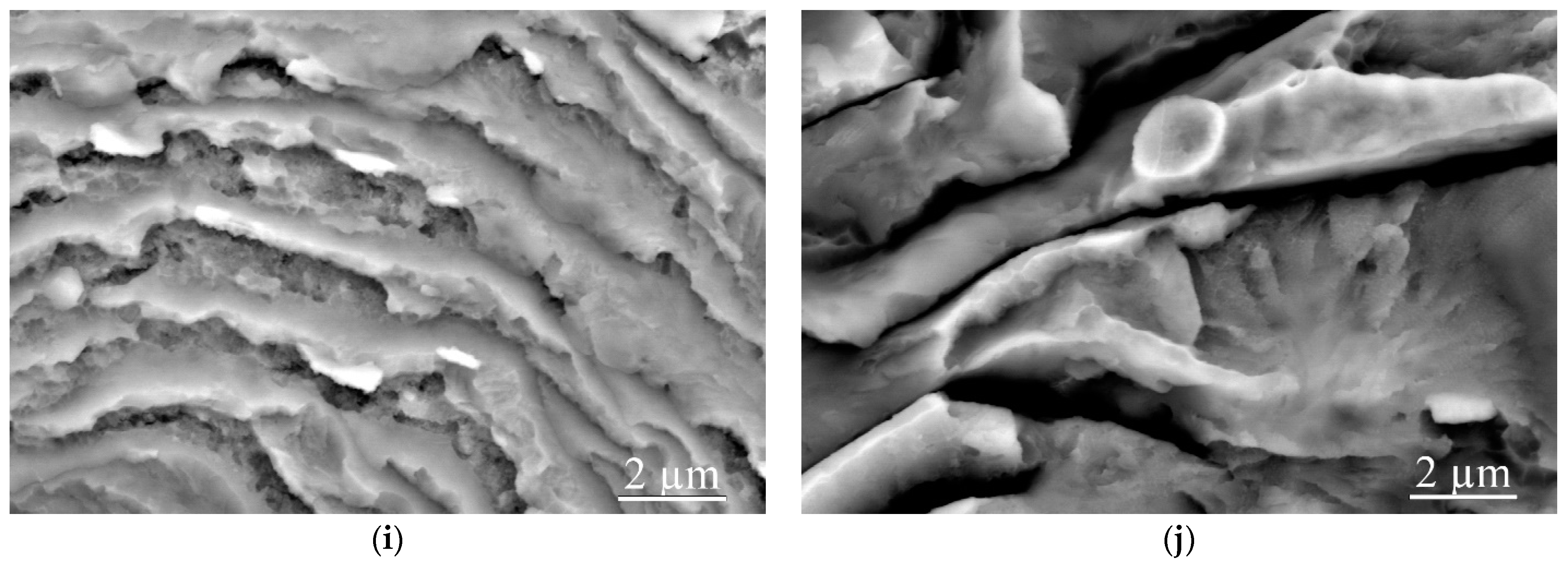
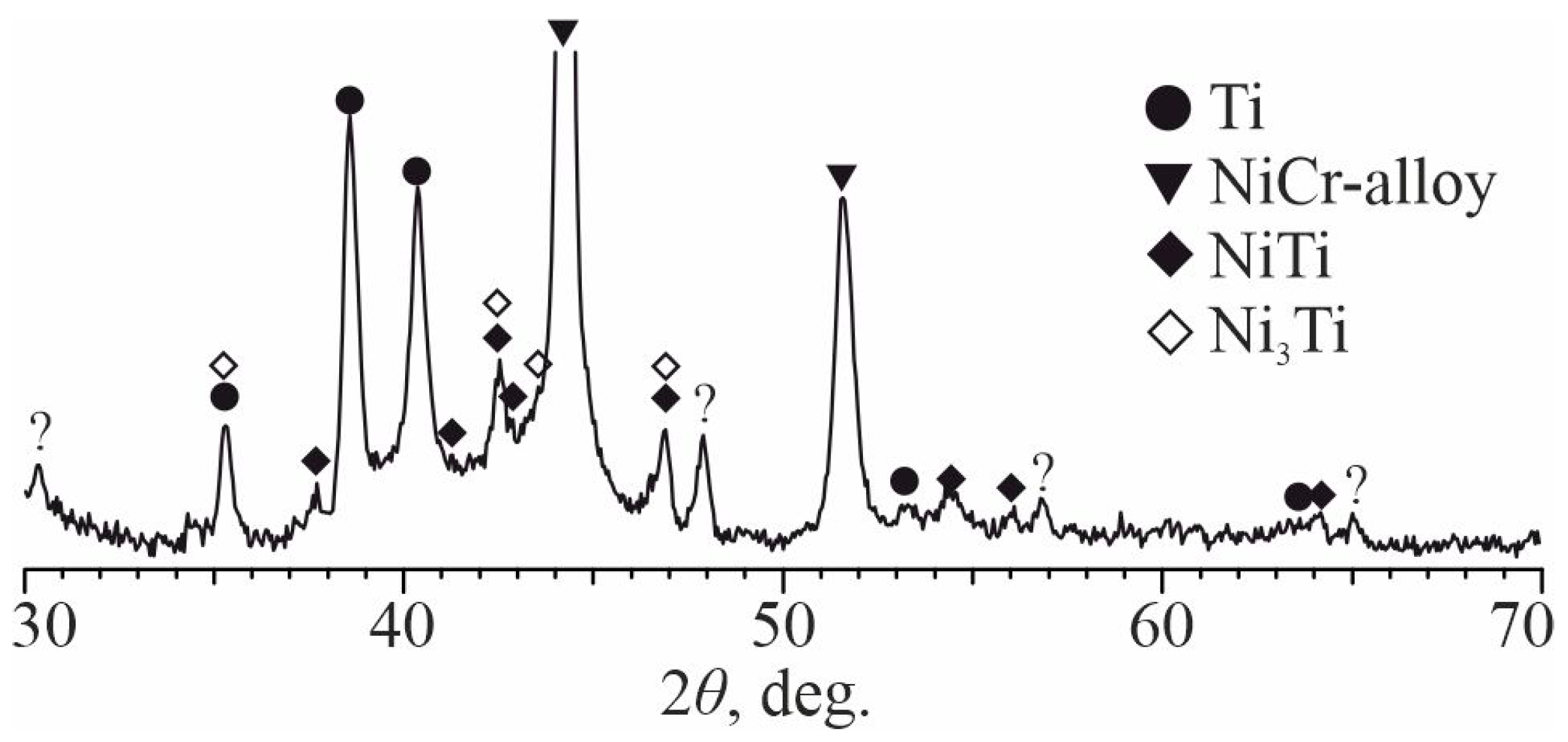
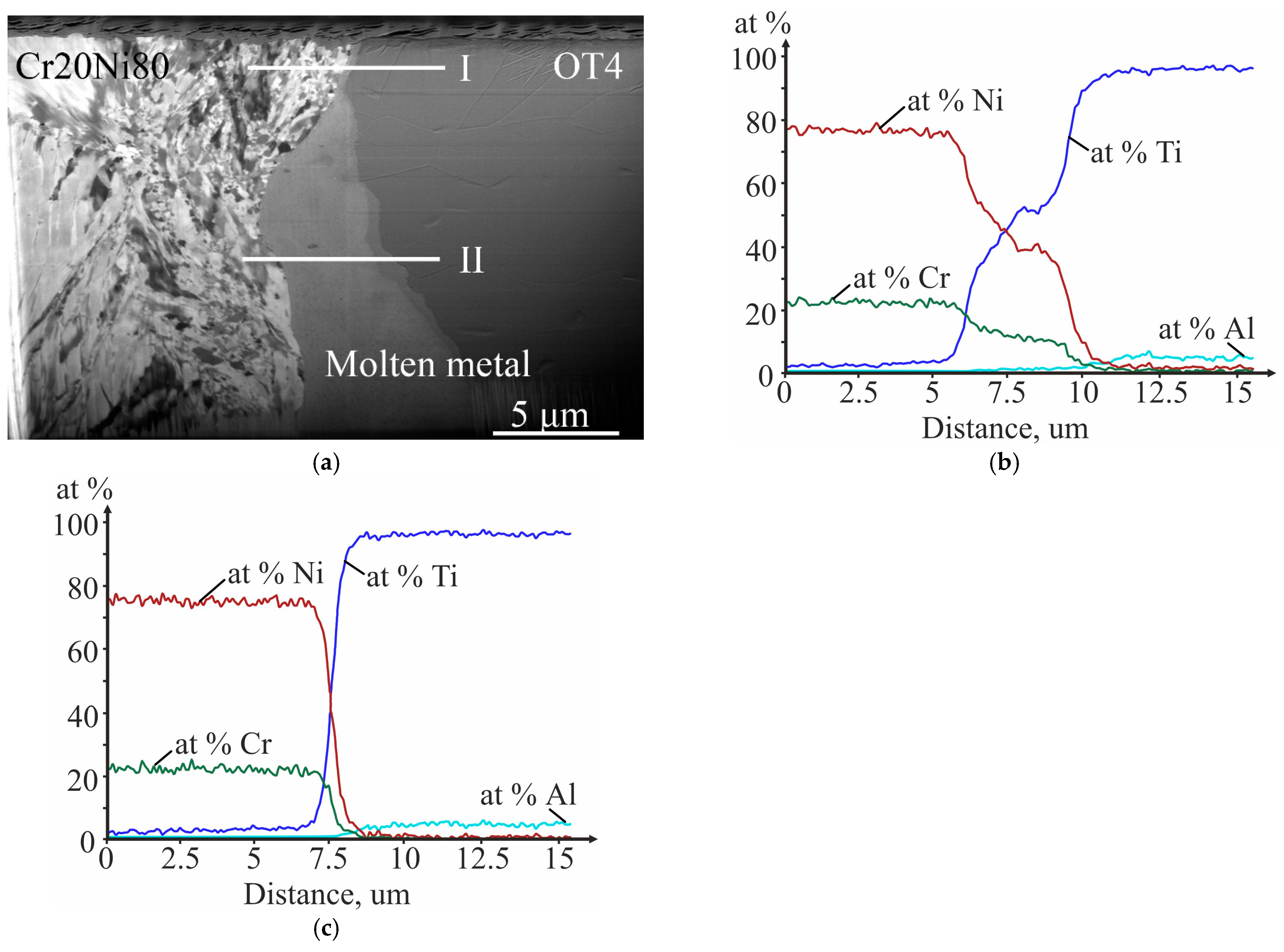
3.1. As-Welded State

At explosive welding at modes close to optimal, an increase in the collision point velocity Vc from 2000 (at an impact velocity (Vi) of 650 m/s) to 3350 m/s (Vi = 1000 m/s) led to an increase in wave parameters (amplitudes from 13 to 26 µm and length from 180 to 295 µm), the relative length of the local molten metal areas (from 20 to 30%), and their maximum thickness (from 4.9 to 7.9 µm) (Figure 2 and Figure 3). The result obtained does not contradict the existing ideas about explosive welding, as it is a type of welding in the solid phase, and it is due to a corresponding increase in the specific kinetic energy spent on plastic deformation of the metal [31].
Along with local molten metal areas, a continuous, clearly distinguishable layer of molten metal was revealed along the entire joint boundary, in which the concentration of components smoothly changes from Cr20Ni80 to OT4 (Figure 4). Moreover, if at Vi = 650 m/s, its thickness was ~250 nm, then at Vi = 1000 m/s it reached 500 nm.
As a result of the peel strength tests, it was found that the strength of the bimetallic samples was 600–700 MPa, regardless of the collision point velocity. In this case, the destruction occurred along the interface between the layers. The fracture surface, in addition to areas of ductile cup fracture and ductile shear, contained fracture areas with round and wavy shapes in the form of detachments (Figure 5).
Figure 6 shows the results of the X-ray phase analysis of the surface of the fractures. The XRD pattern showed intense peaks corresponding to Ti, peaks of the Ni(Cr) solid solution, as well as peaks corresponding to NiTi and Ni3Ti intermetallic compounds. Unidentified peaks were also observed, which may belong to unstable crystalline phases formed during the welding and subsequent rapid cooling.

3.2. Calculation of the Cooling Rate and the Lifetime of the Molten Metal in the Liquid State during the Welding Process

To calculate the cooling rate of local molten metal areas, which can be represented by cylinders located perpendicular to the direction of the explosive welding process, the equation of an instantaneous linear source was used [35]:
T r , t = Q 1 4 π λ t exp r 2 4 α t b t ,
To calculate the cooling rate of a continuous layer of thickness δ, the equation of an instantaneous flat source was used [35]:
T ( r , t ) = Q 2 c γ ( 4 π α t ) 1 / 2 exp x 2 4 α t b t ,
where Q1 is the linear intensity of the source, equal to the heat content per unit length of the local molten metal area; Q2 is the surface intensity of the source, equal to the heat content per unit area of the molten metal interlayer; r is the distance from the source to the point of the body with the determined temperature; t is time interval from the end of the source; λ is coefficient of thermal conductivity; α is coefficient of thermal diffusivity; b is the coefficient of surface heat transfer; x is the distance from the source to the point of the body with the temperature of interest; c is the heat capacity; and γ is the density.
Equating r, x, and b in Equations (2) and (3) to zero and differentiating them with respect to time and excluding the latter, we obtained formulas for calculating the cooling rates of the resulting molten metal at a given temperature.
V = 4 π λ T 2 Q 1   ( f o r   l o c a l   m o l t e n   m e t a l   a r e a s )
V = 2 π λ c γ T Q 2 2 3   ( f o r   c o n t i n u o u s   m o l t e n   m e t a l   l a y e r )
where V is the desired instantaneous molten metal cooling rate at a given temperature T.
The thermal intensity of an instantaneous linear source was determined as the heat accumulated by a unit length of a local molten metal area with a cross-sectional area F:
Q 1 = F γ ( c · T m + S m )
The thermal intensity of an instantaneous flat source was determined as the heat accumulated by a unit area of a continuous molten metal layer of thickness δ:
Q 2 = δ γ c T m + S m
where Tm and Sm are the temperature and specific heat of melting of the molten metal.
The following assumptions were made in the calculations:
-
The values of γ, c, and Sm for the molten metal are determined by the mixture rule;
-
The values of the constants of the metals that make up the alloy are used at a normal temperature (Table 4).
-
The maximum molten metal temperature Tm was assumed to be equal to the liquidus temperature of the Ti-Ni-Cr system alloy with a similar chemical composition [36];
-
The solidus temperature Ts under conditions of high cooling rates is equal to 0.5 times the absolute melting temperature of the NiCr alloy;
-
The average molten metal cooling rate Vave in the crystallization interval is equal to the arithmetic mean of the cooling rates at the boundary points of the liquidus (VTm) and solidus (VTs) intervals;
-
Taking into account the heat transfer to two semi-infinite plates, we used the effective coefficient of thermal conductivity
λ = (λTi + λNiCr)/2
The lifetime of the molten metal was estimated as
τ m = ( T m T s ) / V ave
The obtained value was considered adequate if the following condition was met:
τ < 2h/Co
where h is the thickness of the welded metals and Co is the speed of sound in the welded metals, i.e., the lifetime of the molten metal must exceed the time of the unloading wave arrival at the contact surface.
The results of calculating the cooling rate and the lifetime of the local molten metal areas and in relation to a continuous interlayer of molten metal are presented, respectively, in Table 5 and Table 6.
The analysis showed that the molten metal cooling rate was quite high and increased from ~1010 K/s for a local molten metal to ~1014 K/s for a continuous layer, while its existence time decreased from 10−8 to 10−11 s. Such a large difference in the time of existence of the local molten metal areas and continuous layer explains the appearance of unidentified peaks in the XRD pattern, which may belong to unstable crystalline phases.
The estimation of the unloading wave arrival time at the contact surface gave a value of ~10−8 s, which is comparable with the existence time of local molten metal areas in the liquid state. It can be assumed that the latter is the reason for the presence of rounded and wavy fracture areas in the form of detachments on the fracture surface. In this case, continuous layers of nanometer size with an amorphous structure, due to the ultra-high cooling rate, induce viscous cup fractures and viscous shear on the fracture surface. A further increase in the area of local molten metal areas, when the welding conditions exceed the optimal ones, should lead to an increase in the lifetime of the molten metal, areas of destruction in the form of detachments, and ultimately to a decrease in the peel strength of the layers.

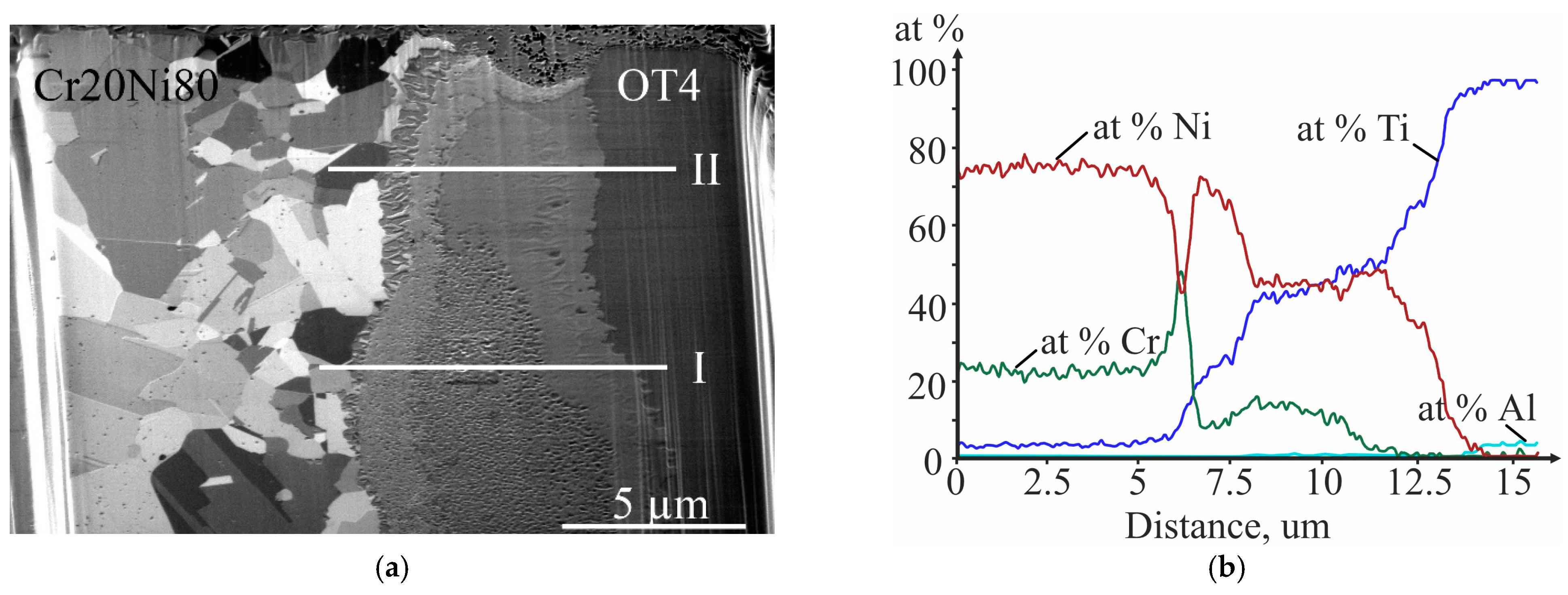
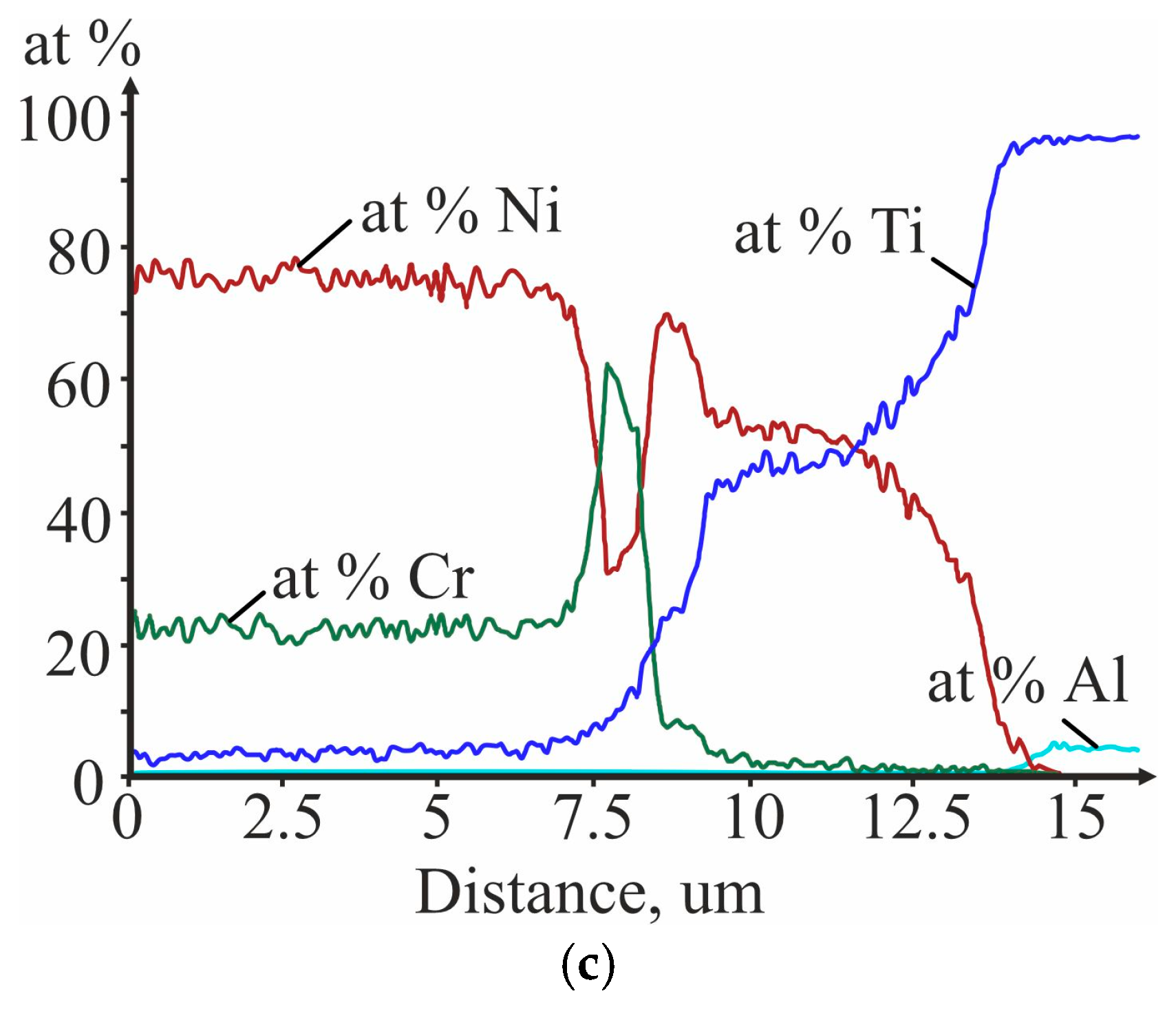
3.3. Investigation of the Initial Stages of Diffusion Interaction during Heating (In Situ)

A region of the interface was chosen for research, where there is simultaneously a molten metal area formed as a result of EW and a zone of titanium with nichrome contact free from molten metal (Figure 7a). After ion polishing of the surface of the area under study and against the background of grains strongly deformed as a result of severe plastic deformation at EW, areas of physical microinhomogeneity in the form of zones with a recrystallized structure were observed. Moreover, it was most pronounced in the Cr20Ni80 structure, which is associated with its lower recrystallization threshold in relation to OT4. Figure 7 also shows the results of the EDS analysis of the chemical element distribution in the area under study with molten metal (Figure 7b) and without it (Figure 7c).
During the heating of the Cr20Ni80 + OT4 composite, it was established by the reference points that the growth of reaction zone occurred mainly due to a change in the thickness of the OT4 layer, i.e., the diffusion gradient was directed towards the titanium alloy (Figure 8). At the location of the molten metal, the reaction zone grew follows its contour. The diffusion processes proceeded at the boundaries of “Cr20Ni80-molten metal” and “molten metal-OT4” without absorption of the molten metal.
It should be noted that, as a result of crystal chemical transformations, the reaction zone growth was accompanied by volumetric changes, which, in turn, due to the presence of a free surface, led to a specific “protrusion” of the reaction zone over the observed surface of the sample (Figure 8).
After completion of the in situ tests (the maximum exposure time was 90 min), the composition and structure of the formed reaction zone were controlled under standard operating conditions of an electron microscope (Figure 9). The analysis showed that the reaction zone consisted of four clearly distinguishable layers. On the side of the titanium alloy layer, a continuous layer of intermetallic Ti2Ni had formed, after which there was an interlayer of intermetallic TiNi, which made up most of the reaction zone. On the NiCr alloy side, a layer of intermetallic compound TiNi3 had formed. In addition, a feature of the reaction zone structure was the formation of a zone with inclusions with a high Cr content, the so-called precipitates (“Cr-rich precipitate”), at the boundary with Cr20Ni80. Moreover, this process was most pronounced in the region of the NiCr/Ti interface free from molten metal, i.e., where the initial content of chromium corresponded to its content in the Cr20Ni80 alloy (20 wt.%). The formation of such inclusions was most likely due to the limited solubility of Cr in intermetallic compounds of the Ti-Ni system.
Due to the high content of Cr in the composition of the molten metal area, after high-temperature tests, a two-phase structure was formed in its place, consisting of the TiNi intermetallic compound and Cr-rich precipitates (Figure 9).
It was also possible to note the changes associated with the occurrence of recrystallization processes throughout the entire volume of the sample, which was expressed in the characteristic structure of the Cr20Ni80 alloy (Figure 9).
As can be seen from Figure 8, during the in situ tests, oxidation of the surface of both the alloys and the reaction zone formed upon heating. This effect is probably due to two factors: the insufficient degree of purity of the Ar used and the high affinity of titanium for some elements (O, H, N, and C).

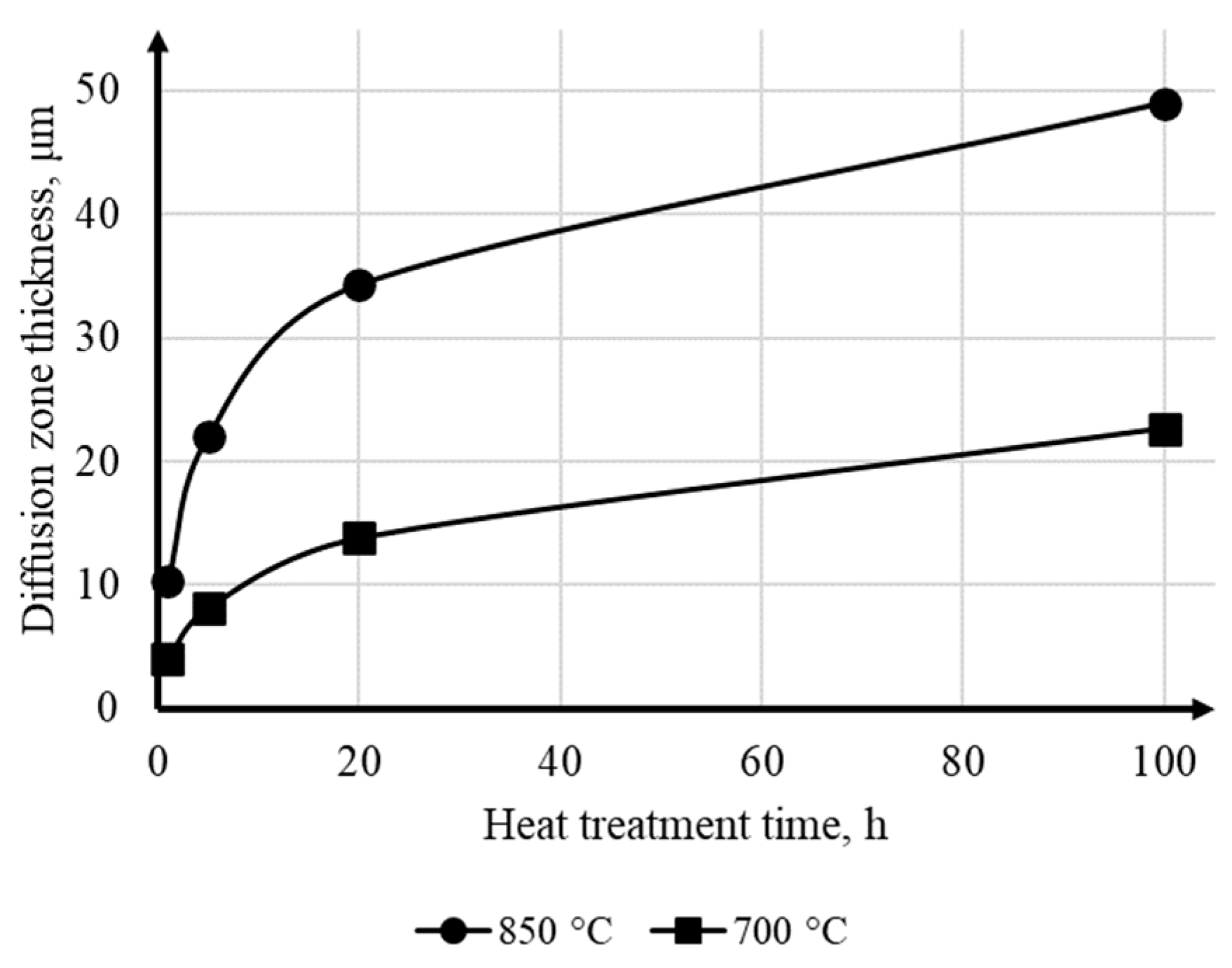
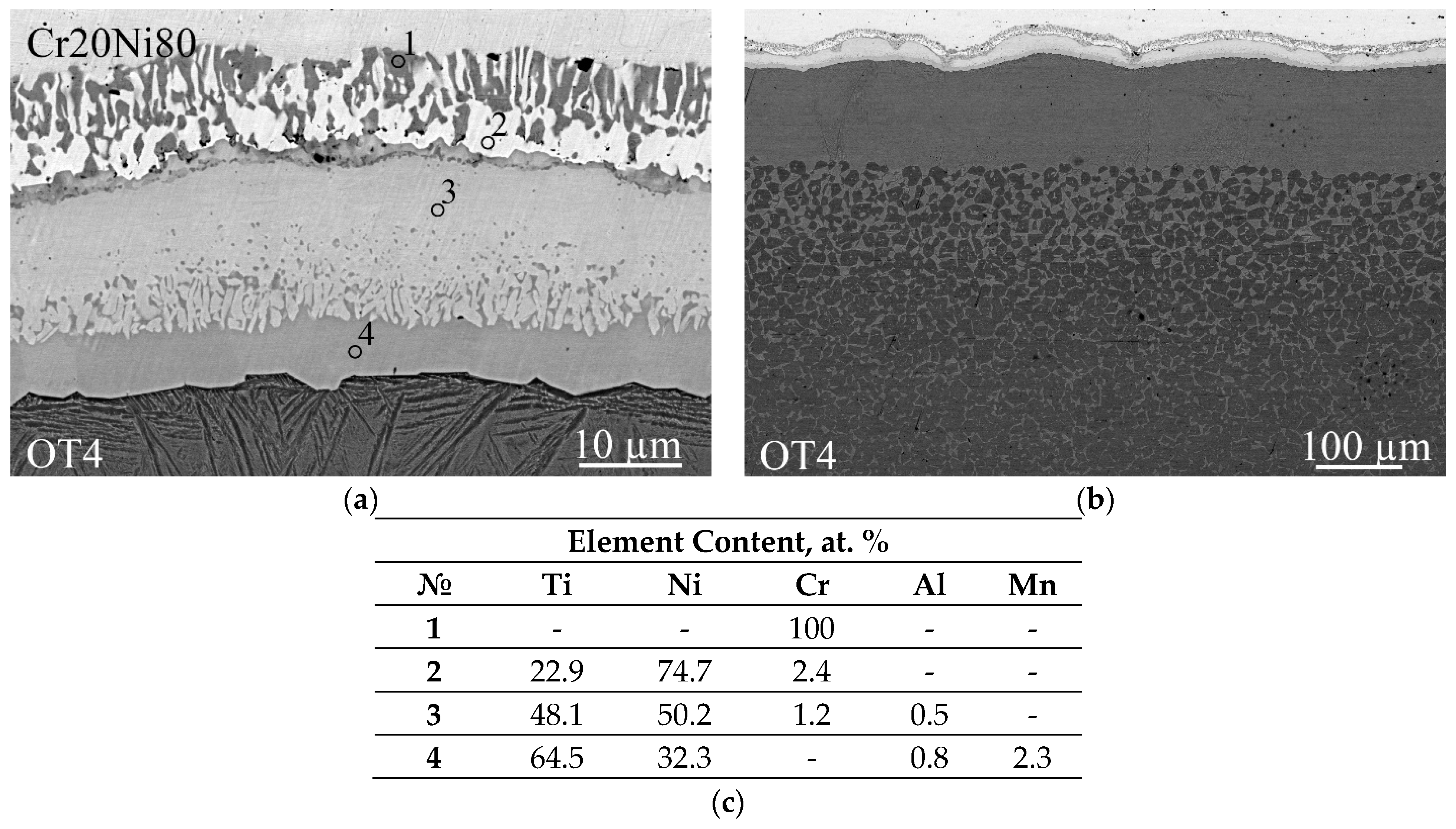
3.4. Investigation of Diffusion Interaction during Heat Treatment

The dependence of the reaction zone thickness formed at the NiCr/Ti interface on the temperature and time of heat treatment were plotted (Figure 10). It was established that, regardless of the heating temperature, the growth law of the reaction zone at the interface is close to parabolic. An increase in the heating temperature above the eutectoid transformation temperature (up to 850 °C) led to a significant intensification of diffusion processes.
Mathematical processing of the obtained experimental data on the dependence of the reaction zone thickness formed at the NiCr/Ti interface on the temperature–time parameters of heating indicates its predominant growth according to the parabolic law characteristic of mutual concentration diffusion. The expression for calculating the thickness of the reaction zone is:
h 2 = 115.14 · exp 91097 R T · τ
The structure of the reaction zone formed at 700 °C after 100 h (Figure 11) was similar to that obtained in the in situ tests. The EDS analysis made it possible to establish that the interlayers that formed in the reaction zone correspond to the region with Cr-rich precipitates, TiNi3 intermetallic compounds, and solid solutions based on TiNi and Ti2Ni intermetallic compounds. The formation of solid solutions was due to the diffusion of alloying components from the OT4 alloy, that is, Al and Mn. In addition, in the region of the OT4 titanium alloy with a depth of 50 μm near the boundary with the reaction zone, there were separate rounded light inclusions of the Ti2Ni intermetallic compound.
The results obtained were confirmed by XRD (Figure 11c). Thus, the reaction zone XRD pattern contained intense peaks of Ti2Ni, as well as weaker peaks of NiTi, Cr2Ti. There were also peaks from the titanium substrate, which was associated with a thinner reaction zone.
An increase in the heating temperature to 850 °C led to qualitative changes in the structure of the reaction zone, as well as the titanium alloy (Figure 12).
Along with a significant intensification of diffusion processes, there was a change in the ratio of the thicknesses of the intermetallic interlayers that make up the reaction zone. On the side of the Cr20Ni80 alloy, the thickness of the TiNi3 intermetallic compound grew. In this case, the fraction of inclusions of the Cr(Ti) solid solution in TiNi3 decreased. A transition region appeared at the interface between the TiNi and Ti2Ni intermetallic compounds, corresponding to a mixture of these phases. As in the case of heating at 700 °C, solid solutions of alloying elements (Al, Mn) formed on the basis of TiNi and Ti2Ni intermetallic compounds. The reaction zone diffraction pattern showed intense Ti2Ni and NiTi peaks, as well as weaker Cr2Ti peaks (Figure 13).
Heating at 850 °C led to active diffusion of Ni directly into the OT4 titanium alloy and the formation of a eutectoid mixture (Ti + Ti2Ni) after cooling. The length of the region with a gradually decreasing Ni content after a 20 h exposure reached 400 µm (Figure 12). It should be noted that the region of the titanium alloy bordering the reaction zone was characterized by a more finely dispersed structure and a uniform distribution of Al and Mn.

4. Conclusions

  • The local areas and thin continuous layers of molten metal formed during explosive welding of the Cr20Ni80 alloy with OT4 titanium alloy are heterogeneous mixtures based on Ni(Cr,Ti) and Ti(Ni,Al) solid solutions and NiTi and Ni3Ti intermetallic compounds. When welding at optimal conditions, an increase in collision point velocity leads to an increase in the average content of titanium in the molten metal.
  • The lifetime of molten metal in the liquid state is comparable with the time of arrival of the unloading wave on the contact surface, which is the reason for the presence of fracture areas in the form of detachments on the fracture surface. Continuous nanometer size molten metal layers with an amorphous structure, due to the ultra-high cooling rate, induce viscous destruction of the interface.
  • Heat treatment at temperatures of 700 and 850 °C leads to the formation of a reaction zone with a layered structure at the NiCr/Ti interface. The reaction zone consists of interlayers of solid solutions based on Ti2Ni, TiNi, and TiNi3 intermetallic compounds, as well as inclusions of a Cr(Ti) solid solution. The diffusion flow gradient is predominantly directed into the titanium alloy. Heat treatment at 700 °C (below the eutectoid transformation point) does not lead to significant changes in the structure of the titanium alloy. Increasing the heat treatment temperature to 850 °C (above the eutectoid transformation point) intensifies diffusion processes at the NiCr/Ti interface and leads to a change in the ratio of intermetallic interlayer thicknesses without affecting their composition. In this case, a near-boundary region with a eutectoid structure (Ti + Ti2Ni) is formed in titanium alloy.

Author Contributions

Conceptualization, A.I.B. and V.G.S.; Methodology, A.I.B. and V.G.S.; Validation, V.P.K.; Investigation, A.I.B. and V.P.K.; Writing—Original Draft Preparation, A.I.B. and V.G.S.; Writing—Review and Editing, A.I.B. and V.G.S.; Visualization, V.P.K. All authors have read and agreed to the published version of the manuscript.

Funding

The work was supported by the Russian Science Foundation, project No. 21-79-10246, https://rscf.ru/en/project/21-79-10246/ (accessed on 7 August 2023).

Data Availability Statement

Data sharing is not applicable.

Acknowledgments

The authors would like to thank to Valentin Kharlamov for assistance with the electron microscopy and energy dispersive X-ray spectroscopy.

Conflicts of Interest

The authors declare no conflict of interest.

References

  1. Sun, Y.; Chen, J.; Ma, F.; Ameyama, K.; Xiao, W.; Ma, C. Tensile and flexural properties of multilayered metal/intermetallics composites. Mater. Charact. 2015, 102, 165–172. [Google Scholar] [CrossRef]
  2. Tian, Y.; Wang, E.; Li, W.; Niu, Z.; Chang, Y.; Guo, C.; Jiang, F. Improved fracture toughness of NiTi shape memory alloy fiber-reinforced Ti-Al metal-intermetallic-laminate composite. J. Alloys Compd. 2018, 739, 669–677. [Google Scholar] [CrossRef]
  3. Wang, H.; Harrington, T.; Zhu, C.; Vecchio, K.S. Design, fabrication and characterization of FeAl-based metallic-intermetallic laminate (MIL) composites. Acta Mater. 2019, 175, 445–456. [Google Scholar] [CrossRef] [Green Version]
  4. Liang, G.; Yuan, M.; Wang, H.; Pei, X.; Zhou, X.; Li, M. Microstructure evolution and mechanical properties of Ti-Ni-Al ternary Metallic-Intermetallic Laminate (MIL) composites. J. Alloys Compd. 2023, 935, 167853. [Google Scholar] [CrossRef]
  5. Hu, L.; Xue, Y.; Shi, F. Intermetallic formation and mechanical properties of Ni-Ti diffusion couples. Mater. Des. 2017, 130, 175–182. [Google Scholar] [CrossRef]
  6. Zhang, Y.; Cheng, X.; Cai, H. Fabrication, characterization and tensile property of a novel Ti2Ni/TiNi micro-laminated composite. Mater. Des. 2016, 92, 486–493. [Google Scholar] [CrossRef]
  7. Mo, T.; Chen, J.; Chen, Z.; He, W.; Liu, Q. Microstructure evolution during roll bonding and growth of interfacial intermetallic compounds in Al/Ti/Al laminated metal composites. JOM 2019, 71, 4769–4777. [Google Scholar] [CrossRef]
  8. Chang, D.; Wang, P.; Zhao, Y. Effects of asymmetry and annealing on interfacial microstructure and mechanical properties of Cu/Al laminated composite fabricated by asymmetrical roll bonding. J. Alloys Compd. 2020, 815, 152453. [Google Scholar] [CrossRef]
  9. Sun, W.; Yang, F.; Kong, F.; Wang, X.; Chen, Y. Interface characteristics of Ti6Al4V-TiAl metal-intermetallic laminate (MIL) composites prepared by a novel hot-pack rolling. Mater. Charact. 2018, 144, 173–181. [Google Scholar] [CrossRef]
  10. Sun, W.; You, F.; Kong, F.; Wang, X.; Chen, Y. Effect of residual stresses on the mechanical properties of Ti-TiAl laminate composites fabricated by hot-pack rolling. Mater. Charact. 2020, 166, 110394. [Google Scholar] [CrossRef]
  11. Szachogluchowicz, I.; Sniezek, L.; Hutsaylyuk, V. Low cycle fatigue properties of AA2519–Ti6Al4V laminate bonded by explosion welding. Eng. Fail. Anal. 2016, 69, 77–87. [Google Scholar] [CrossRef]
  12. Mali, V.I.; Bataev, A.A.; Maliutina, I.N.; Kurguzov, V.D.; Bataev, I.A.; Esikov, M.A.; Lozhkin, V.S. Microstructure and mechanical properties of Ti/Ta/Cu/Ni alloy laminate composite materials produced by explosive welding. Int. J. Adv. Manuf. Technol. 2017, 93, 4285–4294. [Google Scholar] [CrossRef]
  13. Kuz’min, E.V.; Lysak, V.I.; Kuz’min, S.V.; Korolev, M.P. Influence of structure formation and properties of bimetal produced by ultrasound-assisted explosive welding. J. Manuf. Process. 2021, 71, 734–742. [Google Scholar] [CrossRef]
  14. Zhao, H.; Zhao, C.; Yang, Y.; Wang, Y.; Sheng, L.; Li, Y.; Huo, M.; Zhang, K.; Xing, L.; Zhang, G. Study on the Microstructure and Mechanical Properties of a Ti/Mg Alloy Clad Plate Produced by Explosive Welding. Metals 2022, 12, 399. [Google Scholar] [CrossRef]
  15. Hu, Y.; Dong, Y.; Huang, X.; Li, C.; Zhang, Z. Microstructure characteristics of a high-entropy-alloy intermetallic laminate composite. Mater. Lett. 2020, 273, 127937. [Google Scholar] [CrossRef]
  16. Liu, K.; Li, Y.; Xia, C.; Wang, J. Microstructural evolution and properties of TLP diffusion bonding super-Ni/NiCr laminated composite to Ti-6Al-4V alloy with Cu interlayer. Mater. Des. 2017, 135, 184–196. [Google Scholar] [CrossRef]
  17. Assari, A.H.; Eghbali, B. Solid state diffusion bonding characteristics at the interfaces of Ti and Al layers. J. Alloys Compd. 2019, 773, 50–58. [Google Scholar] [CrossRef]
  18. Padamata, S.K.; Yasinskiy, A.; Yanov, V.; Saevarsdottir, G. Magnetron Sputtering High-Entropy Alloy Coatings: A Mini-Review. Metals 2022, 12, 319. [Google Scholar] [CrossRef]
  19. Noro, J.; Ramos, A.S.; Vieira, M.T. Intermetallic phase formation in nanometric Ni/Al multilayer thin films. Intermetallics 2008, 16, 1061–1065. [Google Scholar] [CrossRef]
  20. Zhou, Q.; Lu, H.; Zhang, Y.; Guo, Y.; Zhu, L.; Huang, G.; Chen, P. Intermetallic Reaction of the Bonding Interface of TA2/Q235 Explosive Welding Composite. Metals 2023, 13, 571. [Google Scholar] [CrossRef]
  21. Malakhov, A.; Epishin, A.; Denisov, I.; Saikov, I.; Nolze, G. Morphology and Structure of Brass–Invar Weld Interface after Explosive Welding. Materials 2022, 15, 8587. [Google Scholar] [CrossRef]
  22. Szachogłuchowicz, I.; Śnieżek, L.; Ślęzak, T. Mechanical Properties Analysis of Explosive Welded Sheet of AA2519-Ti6Al4V with Interlayer of AA1050 Subjected to Heat-Treatment. Materials 2022, 15, 4023. [Google Scholar] [CrossRef] [PubMed]
  23. Kwiecien, I.; Wierzbicka-Miernik, A.; Szczerba, M.; Bobrowski, P.; Szulc, Z.; Wojewoda-Budka, J. On the Disintegration of A1050/Ni201 Explosively Welded Clads Induced by Long-Term Annealing. Materials 2021, 14, 2931. [Google Scholar] [CrossRef]
  24. Li, H.; Cao, L.; Liang, X.; Zhang, W.; Wu, C.; Zeng, Z.; Zhou, C. Influence of Rolling Temperatures on Interface Microstructure and Mechanical Properties of Multi-Pass Rolling TA1/Q235B Explosive Welded Sheets. Metals 2020, 10, 1654. [Google Scholar] [CrossRef]
  25. Trykov, Y.P.; Shmorgun, V.G. Evaluation of the impact toughness of explosion-welded joints. Weld. Int. 2002, 16, 415–416. [Google Scholar] [CrossRef]
  26. Trykov, Y.P.; Shmorgun, V.G.; Abramenko, S.A. Influence of rolling on the properties of titanium—Steel composite obtained by explosive welding. Steel Transl. 2005, 35, 61–62. [Google Scholar]
  27. Greenberg, B.A.; Ivanov, M.A.; Pushkin, M.S.; Inozemtsev, A.V.; Patselov, A.M.; Tankeyev, A.P.; Kuzmin, S.V.; Lysak, V.I. Formation of Intermetallic Compounds During Explosive Welding. Metall. Mater. Trans. A Phys. Metall. Mater. Sci. 2016, 47, 5461–5473. [Google Scholar] [CrossRef]
  28. Shmorgun, V.G.; Bogdanov, A.I.; Arisova, V.N.; Trykov, Y.P. Growth kinetics of the diffusion zone at the interface of the explosion-welded nickel–aluminium composite. Weld. Int. 2016, 30, 625–629. [Google Scholar] [CrossRef]
  29. Shmorgun, V.G.; Trykov, Y.P.; Slautin, O.V.; Metelkin, V.V.; Bogdanov, A.I. The kinetics of diffusion processes in the nickel-aluminum composition. Russ. J. Non-Ferr. Met. 2009, 50, 286–289. [Google Scholar] [CrossRef]
  30. Shmorgun, V.G.; Slautin, O.V.; Kulevich, V.P.; Serov, A.G. Formation of the Interaction Zone on the Interlayer Boundary of the Explosion-Welded Composite VT1-0–NP2. Inorg. Mater. Appl. Res. 2020, 11, 98–102. [Google Scholar] [CrossRef]
  31. Gurevich, L.M.; Shmorgun, V.G.; Bogdanov, A.I.; Taube, A.O.; Storozheva, E.I. Kinetics of the diffusion interaction on the “melt–solid body” boundary in explosive welded Al-Ni composite. Mater. Today Proc. 2019, 19, 1904–1907. [Google Scholar] [CrossRef]
  32. Sha, W.; Malinov, S. (Eds.) Titanium Alloys: Modelling of Microstructure, Properties and Applications; Woodhead Publishing: Cambridge, UK, 2009; p. 569. [Google Scholar]
  33. Perepezko, J.H. The hotter the engine, the better. Science 2009, 326, 1068–1069. [Google Scholar] [CrossRef]
  34. Shmorgun, V.G.; Bogdanov, A.I.; Kulevich, V.P.; Taube, A.O. Experimental research of the explosive welding of metal plates with different initial hardness. Mater. Manuf. Process. 2023. [Google Scholar] [CrossRef]
  35. Kasuya, T.; Yurioka, N. Prediction of Welding Thermal History by a Comprehensive Solution. Weld. J. Res. Suppl. 1993, 72, 107–115. [Google Scholar]
  36. Hu, B.; Du, Y.; Schuster, J.C.; Sun, W.; Liu, S.; Tang, C. Thermodynamic modeling of the Cr–Ni–Ti system using a four-sublattice model for ordered/disordered bcc phases. Thermochim. Acta 2014, 578, 35–42. [Google Scholar] [CrossRef]
Figure 1. Explosive welding scheme. 1—chipboard, 2—titanium alloy, 3—Cr20Ni80 alloy, 4—stand-off distance, 5—explosive charge, 6—electric detonator.
Metals 13 01417 g001
Figure 2. The structure of the NiCr/Ti interface after explosive welding at the optimal mode at Vc 2000 (a) and 3350 m/s (b).
Metals 13 01417 g002
Figure 3. The structure of the molten metal at the NiCr/Ti interface after explosive welding at the optimal mode at Vc 2000 (a) and 3350 m/s (b).
Metals 13 01417 g003
Figure 4. The structure of the continuous molten metal layer at the NiCr/Ti interface after explosive welding at the optimal mode at Vc 3350 m/s (a) and the distribution of chemical elements in the cross-section (b).
Metals 13 01417 g004
Figure 5. The structure of the fracture zone on the NiCr alloy side (a,c,e,g,i) and on the titanium alloy side (b,d,f,h,j) at different magnifications.
Metals 13 01417 g005aMetals 13 01417 g005b
Figure 6. XRD patterns from the fracture site (unidentified phases are indicated with “?”).
Metals 13 01417 g006
Figure 7. The structure (a) and the distribution of chemical elements at the NiCr/Ti interface with molten metal (I) (b) and without it (II) (c) before in situ tests.
Metals 13 01417 g007
Figure 8. SEM images of the NiCr/Ti interface during heating at 850 °C for (a) 1 min, (b) 15 min, (c) 50 min, and (d) 90 min (in situ).
Metals 13 01417 g008
Figure 9. The structure (a) and the distribution of chemical elements at the NiCr/Ti interface with molten metal (I) (b) and without it (II) (c) after in situ tests (850 °C, 90 min).
Metals 13 01417 g009aMetals 13 01417 g009b
Figure 10. Reaction zone growth kinetics.
Metals 13 01417 g010
Figure 11. The structure of the reaction zone at the NiCr/Ti interface after heat treatment at 700 °C for 100 h (a); the results of point EDS analysis (b) and XRD analysis (c).
Metals 13 01417 g011
Figure 12. The structure of the reaction zone at the Cr20Ni80 + OT4 boundary (a) and OT4 titanium alloy in the border area (b) after heat treatment at 850 °C for 20 h, and the results of point EDS analysis (c).
Metals 13 01417 g012
Figure 13. XRD pattern of the reaction zone after heat treatment at 850 °C for 20 h.
Metals 13 01417 g013
Table 1. Chemical composition of OT4 titanium alloy.
TiAlVMoZrMnSiFe
91.638–95.73.5–5--≤0.30.8–2≤0.15≤0.3
Table 2. Chemical composition of the Cr20Ni80 alloy.
AlCCrFeMnNiPSSiTiZr
≤0.20≤0.0620.0–23.0≤1.0≤0.60base≤0.020≤0.0151.00–1.50≤0.200.20–0.50
Table 3. EW modes.
Table 3. EW modes.
ModeHeight of the Explosive Charge,
mm
Stand-Off Distance,
mm
Vc,
m/s
Vi,
m/s
I403.52000620
II333501000
Table 4. Physical characteristics of the metals used in the calculations.
MetalsDensity, kg/m3Specific Heat of Melting, kJ/kgSpecific Heat,
J/(kg × K)
Nickel89003030.46
Titanium45403580.54
Chromium71902640.448
Table 5. The cooling rate and the lifetime of a local molten metal area in the liquid state.
Average Area of Local Molten MetalWeighted Average Nickel ContentLiquidus
Temperature
Solidus
Temperature
Cooling RateMolten Metal Lifetime
F × 10−9, m2mNi, at. %Tm, KTS, KV × 1010, K/sτm × 10−8, s
0.64216008363.22.3
Table 6. The cooling rate and the lifetime of a continuous molten metal layer in the liquid state.
Average Area of Continuous Molten MetalWeighted Average Nickel ContentLiquidus
Temperature
Solidus
Temperature
Cooling RateMolten Metal Lifetime
F × 10−9, m2mNi, at. %Tm, KTS, KV × 1014, K/sτm × 10−11, s
3.02813708361.00.5
Disclaimer/Publisher’s Note: The statements, opinions and data contained in all publications are solely those of the individual author(s) and contributor(s) and not of MDPI and/or the editor(s). MDPI and/or the editor(s) disclaim responsibility for any injury to people or property resulting from any ideas, methods, instructions or products referred to in the content.

