
Internal Hydroforming of Large Stainless-Steel Eggshells from Stepped Preforms

1
School of Mechanical Engineering, Jiangsu University of Science and Technology, Zhenjiang 212003, China
2
State Key Laboratory of Deep-Sea Manned Vehicles, China Ship Scientific Research Center, Wuxi 214082, China
*
Author to whom correspondence should be addressed.
Metals 2023, 13(8), 1352; https://doi.org/10.3390/met13081352
Submission received: 30 June 2023
/
Revised: 24 July 2023
/
Accepted: 26 July 2023
/
Published: 27 July 2023
(This article belongs to the Special Issue Mechanical Failure and Metal Degradation of Ships and Marine Structures (Volume II))
Abstract
:The internal hydroforming of large stainless-steel eggshells from a stepped preform is investigated in this paper. The nominal major and minor axes of the eggshell were 1537 and 1070 mm, respectively. The stepped preform was fabricated from thin-walled (1.9 mm thick) stainless-steel sheets and comprised twelve conical segments inscribed inside the target eggshell. The preform was then hydroformed, and its wall thickness and shape were measured. The yield load distribution and material hardening of the hydroforming process were investigated analytically. Nonlinear finite-element analyses were employed to further investigate hydroforming behaviors and the effect of weld lines on hydroforming. The experimental, numerical, and analytical results were consistent. The results confirm that, during the hydroforming process, considerable springback occurs for large eggshells, which greatly affects forming precision. However, this effect can be reduced by accounting for the strengthening effect of weld lines.
1. Introduction
The eggshell shape is a new and promising shape for submarine pressure structures. Its advantages include its favorable weight to strength ratio, high load-bearing capacity, efficient space utilization, and optimal material distribution. Wong demonstrated in their article that eggshells could achieve remarkable weight to strength ratios, highlighting their natural efficiency under specific conditions [1]. Chen and Sha combined principles of bionics and architecture, asserting that, despite their thinness, eggshells could withstand significant pressure before fracturing [2]. Narushin and Romanov advocated for the use of Narushin’s model over Hügelschäffer’s model for designing egg-shaped building structures, citing optimal geometry in terms of material costs per unit of internal capacity and favorable shell-strength characteristics [3]. Zhang et al. investigated the buckling performance of egg-shaped pressure hulls under uniform external pressure and concluded that such hulls could be optimally coordinated based on factors, such as strength, buoyancy reserve, and space efficiency [4]. Imran et al. contributed to the field by providing an optimized design for composite egg-shaped pressure hulls, which could be utilized for manufacturing or further investigation [5]. Additionally, Wu et al. conducted research on the acoustic radiation of composite egg-shaped pressure hulls [6]. These studies collectively confirm the unparalleled advantages of eggshells for underwater applications. Moreover, egg geometries have found application as pressure vessels for sludge digesters [7,8,9] and domed building roofs [10,11,12] in inland areas. However, fabricating large eggshell shapes is challenging due to the unevenly distributed positive Gaussian curvature. Additionally, imperfections introduced during fabrication and assembly as well as damage and loading while in service can adversely affect the hydrostatic stability and through-life of eggshell structures [13].
Common techniques for fabricating shells of revolution include computerized numerical control (CNC) machining, stamping, hydroforming, and rapid prototyping. CNC machining can produce a variety of shells, such as ellipsoidal [14], barreled [15,16], conical [17], and egg-shaped [18], at a laboratory scale; however, it has limitations when it comes to manufacturing large shells and may affect surface integrity. Cold and hot stamping are commonly used for fabricating small and large thin shells [19,20,21,22]; however, this approach requires using expensive dies and presses to ensure the forming accuracy of the parts, and cracking is also common.
Tube hydroforming has recently attracted attention in the automotive, aeronautic, and aerospace industries [23,24]. Sun et al. presented a novel approach for improving the deformation distribution and processing accuracy of egg-shaped shells by using a flexible rubber medium for unidirectional loading and bulging [25,26]. Nevertheless, the hydroforming process for tubing has the drawback of slow cycle times and necessitates expensive hardware. Additionally, the lack of an extensive knowledge base for designing the process and necessary tools is a significant issue [27]. Rapid prototyping methods, such as additive manufacturing, can be employed to produce atypical shells of revolution directly from CAD models, such as corrugated [28,29], oval-shaped [30], and egg-shaped shells [31]. Additive manufacturing avoids many of the disadvantages of the traditional manufacturing process, such as producing metal dies, which is typically expensive and requires long manufacturing cycles and is therefore effective for producing small and complex parts. However, additive manufacturing may not be a feasible method for producing large shells, and achieving the desired load-bearing capacity can present challenges because the model is physically realized through deposition of successive layers of material.
Hydroforming is a flexible, effective, and inexpensive method for fabricating shells of revolution and is superior to conventional die forming [32,33]. Polyhedral preforms can be used to directly hydroform various shells of revolution, including spheres, toroids, and ellipsoids, eliminating the need for dies [34]. The hydroforming technique was first invented by Wang, who successfully manufactured single-layer spherical shells [35,36,37,38]. Building on this research, Yuan and Teng extended the technique to fabricate ellipsoidal and toroidal shells [39,40,41,42]. They discovered that wrinkles can easily appear in the equatorial zone of oblate ellipsoids and the inner zone of toroids. Zhang later conducted research on preform designs for ellipsoidal shells combined with double generating lines, as well as the hydroforming of ellipsoidal shells with the same feature [43,44,45,46], and effectively avoided wrinkling in the equatorial zone and insufficient hydroforming at the two ends. The integral hydroforming of multilayered spherical shells was examined by Hashemi [47,48,49], who used football-shaped preforms and applied physical and geometrical adjustment principles to produce satisfactory spheres. Recently, Jing and colleagues developed an innovative integral method of hydro-bulge-forming, which was employed for the fabrication of a novel spherical pressure hull structure located in deep-sea environments [50,51]. They confirmed the performance and effectiveness of the method by subjecting the formed spherical pressure hull to uniform external pressure, which revealed crushing and buckling characteristics.
In the past two years, Zhang and colleagues utilized hydroforming techniques to produce small egg-shaped shells [52,53,54] and barreled frustums [55]. The egg-shaped shells were formed through internal pressurization of petal-shaped preforms, while conical preforms were used for the barreled frustums. The collapse behavior of the hydroformed shells under hydrostatic pressure was examined experimentally and through numerical modeling. The experimental results were consistent with numerical simulations, demonstrating the effectiveness of hydroforming in creating non-standard shells that could withstand external pressure. However, most studies focus on exploring the reliability of the theory and methods for laboratory-scale models. Few studies have performed the precise manufacturing of large eggshell shapes or investigated the effects of springback and weld lines on the hydroforming results; the relevant experimental data are still scarce.
Therefore, this study focuses on the internal hydroforming of large eggshells from a stepped preform. Section 2 introduces the geometric dimensions of the preform, preform fabrication, measurement, hydroforming, and testing procedures. Section 3 compares the experimental and numerical hydroforming results, discusses the impact of weld lines on the hydroforming results, and conducts an analytical analysis of material hardening. Section 4 concludes the study with the main findings and recommendations for further research.
2. Materials and Methods
This section describes the geometric parameters of and process for fabricating the stepped preform. The hydroforming performance of the produced eggshell when it was subjected to internal pressurization was investigated experimentally through hydroforming tests, wall thickness measurements, and geometric comparisons. Subsequently, the numerical analysis of the eggshell hydroforming results was performed using geometrical and material nonlinear analyses with the Newton–Raphson method in ABAQUS/Standard software (Version 6.14, Dassault Systèmes, Vélizy-Villacoublay, France).
2.1. Geometric Design and Fabrication
In this study, a stepped preform was assumed to be inscribed inside the target eggshell. This assumption has been commonly applied in studies where spheres [35,36,37,38], toroids [39,40,41,42], and ellipsoids [43,44,45,46] have been hydroformed. According to this general inscribing assumption, the geometry and dimensions of the preform segments have weak influences on the hydroforming results within a certain range. However, by increasing the number of segments, the hydroforming accuracy can be improved. The mathematical description of the external contours of the stepped preform and eggshell can be found in Equations (1) and (2), respectively:
where the subscript i corresponds to the segment number, and 12 conical segments are inscribed inside the eggshell shown in Figure 1. Here, fi(x) represents the circumferential radius (mm) of the ith conical segment of the stepped preform, and ki and bi (mm) are determined in accordance with the Cartesian coordinate system (values are listed in Table 1). Furthermore, q(x) represents the circumferential radius (mm) of the eggshell, and (xi, yi) and (xi+1, yi+1) are the Cartesian coordinates of the endpoints of the ith segment. The nominal dimensions of the designed stepped preform and eggshell are listed in detail in Table 2.
The sharp pole of the designed stepped preform was closed using a thick circular closure with an inlet hole installed at the center to enable internal pressurization. The blunt pole was closed using a circular pole sheet. These closures can be replaced with heavy flanges if the eggshell is used as an underwater pressure hull for a vehicle to enable the installation of windows or access ports [56].
The basic material used in this case was a 304 stainless-steel thin sheet, which is commonly available in the market and belongs to the austenitic stainless-steel grade [57]. According to the information provided by the market supplier, the rolling direction of the grade 304 stainless-steel thin sheets was longitudinal. The 304 stainless-steel thin sheet was delivered as a cold-rolled material from the market supplier (prior to cutting, bending, or forming). The material was assumed to be isotropic. The stainless-steel material was 06Cr19Ni10 stainless steel, and its chemical composition was as follows: C was 0.08%, Si was 0.75%, Mn was 2.00%, Cr was 18.00–20.00%, and Ni was 8.00–10.50% [58]. The basic physical characteristics of the material were defined as follows: Young’s modulus: E = 180 GPa, Poisson’s ratio: μ = 0.3, density: ρ ≈ 7.93 g/cm3, thermal conductivity: λ ≈ 16.2 W·m−1·K−1, and linear expansion coefficient: αt ≈ 17.3 × 10⁻⁶ °C−1. These data sources were provided by the market supplier and complied with the GB/T 3280-2015 standard [57]. The DH5902 data acquisition system, manufactured by Donghua Test Technology in China, was widely utilized in stress and strain testing applications. In this study, it served as a crucial tool for accurately measuring the Poisson’s ratio (μ), which was calculated by examining the ratio between the transverse and longitudinal strains. The strain indication error was ±0.3% and the working frequency was 50 Hz. The starting mechanical properties were defined as follows: yield strength: σy = 286 MPa, tensile strength: σb = 784 MPa, and elongation: e = 41.25%. These parameters were obtained from a flat coupon uniaxial tensile test [59]. The mechanical analysis utilized elastic–plastic material modeling. The true stress–strain curve obtained from the uniaxial tensile test is shown in Figure 2. The material model was bilinear. Young’s modulus (E) was determined on the basis of the slope at the first linear stage, whereas Poisson’s ratio (μ) was determined as the ratio of the transverse to longitudinal strain. The yield strength (σy) was defined as the 0.2% proof stress, and the strength coefficient (K) was determined from the slope of the second linear stage. The specific material parameters used in the theoretical and numerical analyses are presented in Figure 2.
A visualization of the manufacturing steps is shown in Figure 3a–e, and photographs of the stepped preform and eggshell are shown in Figure 1. The fabrication process for the stepped preform involved blanking, bending, assembly, and tungsten inert gas (TIG) welding of a stainless-steel sheet. TIG welding can ensure higher welding quality and superior continuity in the weld lines than cold welding [54]. Fabrication began with the CNC laser cutting of fan-shaped sheets of various sizes, the pole sheet, and the thick closure. The meridian length of each segment was determined as its fan width. Experienced technicians carefully bent each fan-shaped sheet into a conical segment; the low thickness of the sheets made it easy to ensure the quality of each bend. Then, each bent conical segment, the pole sheet, and the thick closure were assembled into a stepped preform and welded together through spot welding. The stepped preform was then acquired by using seam welding to close the boundaries of each conical segment. The external surface of the final sample was manually ground to ensure a smooth surface after welding. Because of the thinness of the structure, no stress relief was required after fabrication.
2.2. Hydroforming Test and Measurement
A hydroforming test was performed by applying quasistatic internal pressure. As shown in Figure 4a, to apply quasistatic loading, tap water was filled into the inlet tube of the stepped preform. The inlet tube was then connected to a hand-operated pressure pump (SRB-30X; Zhenhuan Hydraulic Apparatus, Taizhou, China) through a pressure hose. The pump had a maximum working pressure of 30 MPa and a maximum flow of 38 mL per stroke. The internal pressure was gradually increased, and an analog pressure gauge installed in the pressure pump recorded the pressure values to ensure a safe operation.
Once the stepped preform was hydroformed, an eggshell was obtained (Figure 4b). The hydroforming pressure was determined to be 1.6 MPa based on the analog pressure gauge. Following this, the water inside the preform was drained, and the wall thickness of the eggshell was measured using an ultrasonic thickness meter (DAKOTA/PX-7; Sonatest, Dakota Ultrasonics, Scotts Valley, CA, USA) with a precision of 0.002 mm. A total of 1440 measurement points were marked on the eggshell, corresponding to the intersections of 24 equally spaced meridian lines and 60 circumferential lines, using a black marker pen. In accordance with the size of each conical segment, five measurement points were selected on each segment in the meridional direction, and manual measurements were performed in a clockwise direction. To eliminate the air layer on the contact surface, a low-viscosity coupling agent (Elecall Electric Corporation, Wenzhou, China) was applied. The distribution of the eggshell wall thickness, determined from the ultrasonic thickness measurements, is presented in Figure 5 and Figure 6.
After the thickness had been measured, the marked points were removed using ethanol (>99.7%). The external geometry of the eggshell was optically measured using an optical scanner, namely, a KSCAN20 scanner (SCANTECH, Hangzhou, China), along with its ScanViewer software (SCANTECH, Hangzhou, China), as shown in Figure 4c. The optical scanner had a resolution of 0.02 mm. Accurate picture stitching could be achieved by simply pasting circular marking stickers on the surface before the measurements were made; spraying a thin layer of contrast aid on the surface was not required, considerably increasing the efficiency of the measurement. ScanViewer software was utilized to produce a computer-aided design model of the eggshell based on the optically measured data. Comparisons of the optically measured geometry of the eggshell with those of the preform and nominal designs are presented in Figure 7 and Figure 8, respectively.
3. Results and Discussion
This section details the experimental and numerical analyses conducted to study the hydroforming process of the eggshell and presents an analysis of the material hardening that occurs under internal pressurization for the preform. The results of the experiment are compared with the corresponding numerical estimates, and the impact of weld lines on hydroforming are also discussed.
3.1. Experimental Analysis
The measured wall thicknesses of the hydroformed eggshell had a nearly uniform distribution in the circumferential direction. The wall thicknesses of the hydroformed eggshell were found to be lower compared to those of the preform. This can be attributed to the increased surface area of the eggshell resulting from the high internal pressure during hydroforming. As shown in Figure 5 and Figure 6, the wall thicknesses near the equator were considerably lower after hydroforming, whereas the wall thicknesses near the sharp and blunt poles changed only slightly. The greatest reduction in wall thickness occurred in the middle of each conical segment; the reductions were smaller near the segment boundaries. This indicates that the hydroforming most affected the thickness in the equatorial zone of the positive-Gaussian eggshell. Moreover, the wall thickness reduction was largely influenced by the degree of hydroforming deformation. Greater hydroforming deformation was associated with a greater reduction in wall thickness [55]. The wall thicknesses of the sharp pole segments of the hydroformed eggshell were 1.876–1.910 mm; those of the blunt pole segments were 1.878–1.908 mm.
Each conical segment of the eggshell changed from a straight meridian to a curved arc. The geometric deviation between the hydroformed eggshell and designed stepped preform is shown in Figure 7. The hydroforming displacement for each conical segment differed slightly; the greatest difference was near the equator, and the deformation of conical segments was low near the sharp and blunt poles. This change was linked to the principal radii of the eggshell. For both the stepped preform and eggshell, the principal radii followed a bell-shaped curve from the sharp pole to the blunt pole for the constant internal pressure and uniform wall thickness [53]. The measurements of the deviations in shape from the designed geometry of the hydroformed eggshell (Figure 8) indicated that the adopted hydroforming technology had reasonable accuracy. Only a small area of insufficient hydroforming was observed at the sharp and blunt poles; this was attributed to the high stiffness of the connection from the conical segment of the sharp pole to the thick closure. The hydroforming accuracy of the sharp and blunt poles depended on how the yield load was distributed on the eggshell, which is explained further in the following theoretical analysis.
3.2. Theoretical Analysis
The yield load of an eggshell can be determined using the membrane theory of shells of revolution subjected to uniform internal pressure [60]. Assuming that the equivalent stress is equal to the material yield point (σe = σy), the yield load (Pf, Pq) of the stepped preform and eggshell can be expressed as follows [53]:
and
where t represents the wall thickness of the stepped preform or eggshell, while R1 and R2 refer to the meridional and circumferential principal radii of the eggshell, respectively. They can be mathematically expressed as follows:
and
By using Equations (3) and (4), the analytical yield load profiles of the stepped preform and eggshell were obtained. As shown in Figure 9, the yield load of the stepped preform was less than that of the eggshell, indicating that suitable plastic deformation under internal pressurization could produce a satisfactory eggshell. However, a sudden load variation was observed at each conical segment boundary in the stepped preform due to geometric discontinuities, which could create a larger edge effect if the bending effect was considered. Any changes to the shape of a shell could significantly affect stress distribution and the edge effect [61]. Both the stepped preform and eggshell exhibited higher yield loads in conical segments near the sharp and blunt poles, implying that the first and twelfth segments did not undergo plastic deformation during hydroforming. In addition, other conical segments near the sharp and blunt poles revealed insufficient hydroforming displacement. The experimental results and analytical predictions in Figure 8 and Figure 9 are in good agreement. These results suggest that for actual manufacturing processes, the hydroforming technique should be optimized to improve the accuracy at which the sharp and blunt poles are hydroformed.
Only the yield loads of the fifth, sixth, and seventh conical segments of the eggshell were below the test value of 1.6 MPa (Figure 9). Therefore, hydroforming these three conical segments into the designed geometry at this pressure was feasible. The yield loads of the remaining conical segments were slightly higher than those of the fifth, sixth, and seventh conical segments, indicating inadequate hydroforming at these segments. Thus, the designed eggshell could be obtained by reducing the wall thickness of these segments to reduce their yield loads, ensuring that hydroforming was sufficient in these locations. Non-uniform wall thickness could ensure the excellent hydroforming of an eggshell by achieving a uniform stress distribution. This approach was favorably validated through theoretical, numerical, and experimental analyses for the hydroforming of prolate ellipsoids from preforms with multiple thicknesses [62].
Material hardening is inevitable during hydroforming but is difficult to evaluate qualitatively in experimental analyses. Therefore, an analytical model of the material hardening of a hydroformed eggshell was constructed with reference to [63,64]. Based on the previous research [65], according to the equivalent volume transformation, the equivalent radial strain (εt), equivalent circumferential strain (εθ), equivalent meridian strain (εφ), and equivalent strain (εeq) of the ith hydroformed segment can be, respectively, determined as follows:
and
where the subscripts 0 and 1 represent the conical segment before and after hydroforming, respectively. During the hydroforming process, as the forming pressure increases, the meridians of each conical segment transition from straight lines to smooth arcs. It is important to note that the volume of the conical segment undergoes changes as a result of its shape alteration. This observation aligns with the previous findings reported in the studies [55,64]. Therefore, the surface area of the ith conical segment before and after hydroforming can be expressed through integration as follows:
and
where Hi represents the axial height of the ith conical segment. Similarly, the volume of the ith conical segment before and after hydroforming can be expressed as follows:
and
The bilinear material model enables a linear constitutive equation (Equation (15)) and the average yield stress of each conical segment after material hardening to be obtained. The calculation results are listed in Table 3 and Table 4. The analytically derived average yield loads are plotted in Figure 10, and a comparative analysis of the analytical and numerical results is presented in the subsequent section.
3.3. Numerical Analysis
This section presents the analytical results for material hardening and compares the numerical and experimental results. Furthermore, the impact of the weld lines on the eggshell hydroforming results is investigated.
3.3.1. Numerical Modeling
The numerical analysis of the eggshell hydroforming results was performed using geometrical and material nonlinear analyses with the Newton–Raphson method in ABAQUS/Standard software. A finite-element model depicting eggshell hydroforming is displayed in Figure 11. Wall thickness was assumed uniform; the average tested value of 1.9 mm was obtained by measuring the parent stainless-steel sheet prior to hydroforming because the variations in the wall thickness of parent stainless-steel sheet were very small. Such an average assumption has been widely utilized in the previous works of Błachut et al. and Zhang et al. [15,16,62]. The thickness of the shell was defined as the symmetrical offset from its mid-surface, and finite shell elements were generated accordingly.
The surfaces of conventional shell elements had positive and negative normal directions, determined by applying the right-hand rule based on the order of specified nodes, as shown in the inset of Figure 11. The full structural scantlings of the eggshell were modeled using shell elements (S4: a four-node, general-purpose shell with finite membrane strains). The inlet tube was replaced with fully blocked constraints, and the sharp pole had all six degrees of freedom set to zero because of the high stiffness of the inlet tube.
To ensure the reliability and accuracy of the numerical calculations, a mesh sensitivity test was conducted. In this test, a specific point (displacement measurement point) on the conical segment near the equator was chosen as the calibration object. The displacement of this point was then computed using different numbers of mesh elements in the eggshell model, all subjected to the same hydroforming load. Figure 12 depicts the process and its corresponding results. Through a careful analysis, we observed that as the number of mesh elements increased, the displacement value of the chosen specific point gradually approached convergence, indicating the stability and consistency of the results. Notably, when the number of mesh elements reached approximately 25,000, the displacement value exhibited convergence, indicating that further increasing the mesh density would not significantly impact the accuracy of the results. Building upon this observation, the shell comprising 32,160 shell elements and 32,162 nodes was selected.
In the numerical analysis, two loading cases were considered: hydroforming and springback. In the hydroforming case, a uniform internal pressure was gradually applied to the preform until an eggshell of satisfactory quality was achieved. The experimental pressure value of 1.6 MPa was used for a comparison with the numerical results. In the springback case, the internal pressure was gradually reduced to zero. A nonlinear static analysis was mostly used for the evaluations due to the quasistatic nature of hydroforming. For the two cases, the solving parameters were set as follows: an initial time increment of 0.1 s, a time period per step of 1 s, a minimum time increment of 1 × 10⁻⁷ s, and a maximum time increment of 0.1 s. The numerical results are displayed in Figure 10, Figure 13, Figure 14 and Figure 15.
3.3.2. Numerical Analysis
The external shape obtained from the numerical simulation is presented in Figure 13. Positive values indicate outward deformations of the simulated eggshell with respect to the experimental eggshell. The experimental data and numerical results exhibited an excellent agreement; the deviations ranged from −1.5 to 1.5 mm. Unlike in the previous research on small-scale eggshells [53,54], no obvious errors were observed at the weld lines in this study (Figure 7, Figure 8 and Figure 13). Local shape differences were identified only in certain areas of the shell due to the significant effect of springback on hydroforming for large shells. The diameter of the weld lines only accounted for 6.2% of the axial height of the entire eggshell. Additionally, the circumferential weld lines embedded in the eggshell were stiff (similar to the stiffness of ring stiffeners) and thus hardly displaced under internal pressure. The influence of springback on hydroforming for large shells could also be observed in the displacement and wall thickness of the shell.
Considerable differences in the displacement and wall thickness of the hydroformed eggshell were observed before and after springback (Figure 14 and Figure 15). The experimental measurements indicated greater hull wall thinning than the numerical results did. This deviation was primarily attributable to two factors. First, the thickness was calculated assuming uniform preform thickness; second, the influence of welding was not considered in the numerical analysis. In the experimental eggshell, the weld lines could relieve the effect of springback and strengthen the hull, transforming it into a rib-stiffened shell. The differences between the numerical and experimental thicknesses may also have been due to shape differences. The wall thickness tended to increase after springback due to elastic deformation. These results suggest that reasonable pressure retention measures should be implemented to reduce the influence of springback to form large and accurate shells in practical hydroforming.
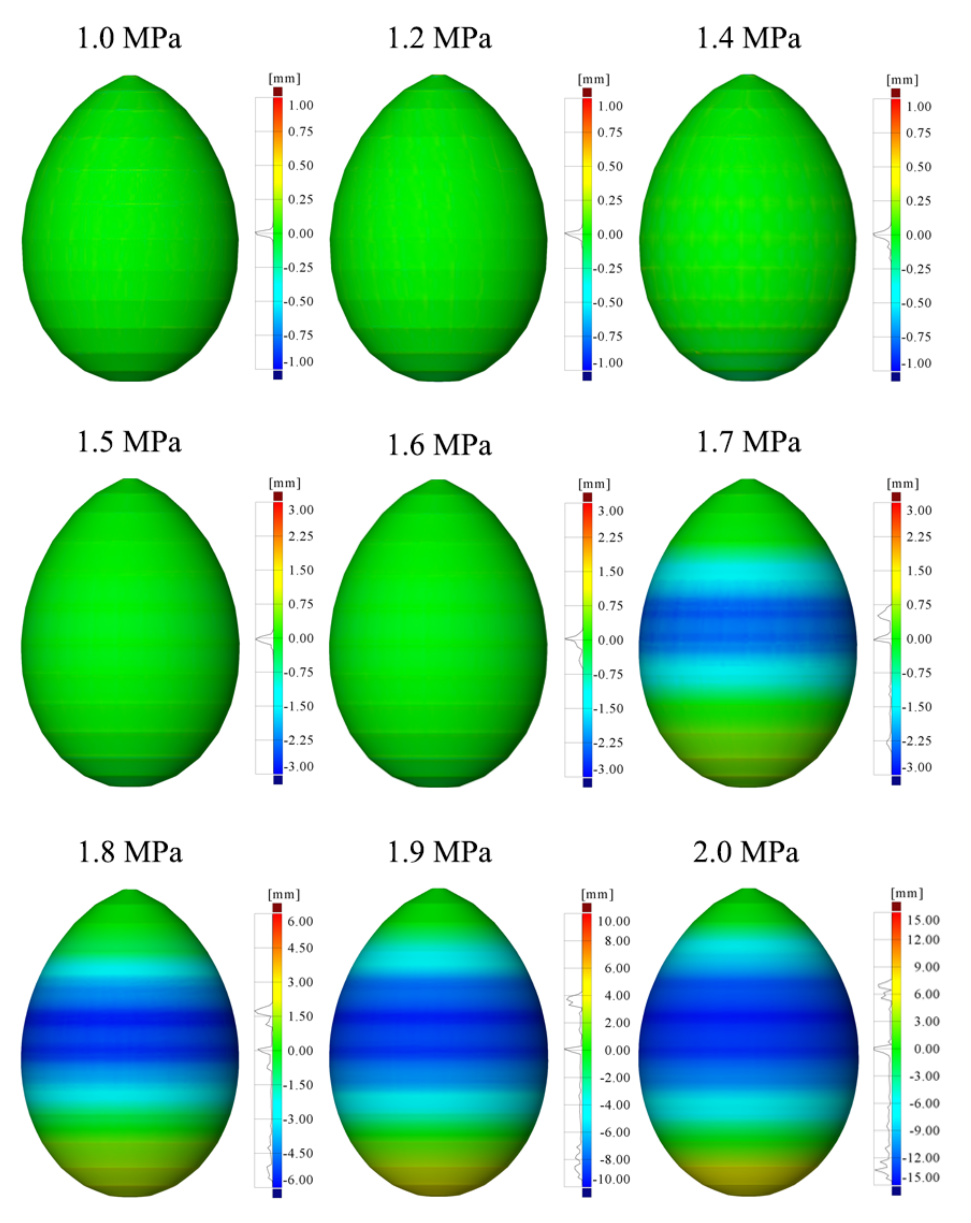
Insufficient hydroforming near the sharp pole was also observed in Figure 14 and Figure 15 because the displacement and wall thickness were little changed after springback. Increases in displacement and reductions in thickness were highly dependent on the amount of hydroforming deformation. Comparing Figure 6 and Figure 7, greater hydroforming deformation clearly resulted in greater changes in the displacement and wall thickness. Therefore, as previously stated, the required hydroforming pressure could be reduced by appropriately reducing the wall thickness to ensure high forming accuracy at the sharp pole.
For areas with sufficient hydroforming, the analytical average yield load of the material hardening was in favorable agreement with the numerical result. The stress distribution of the hydroformed eggshell is displayed in Figure 10. For the fourth through eighth conical segments, the analytically predicted and numerical average yield loads were approximately equal; however, the analytical values were much higher near the sharp and blunt poles, indicating that hydroforming was insufficient at these locations, which was consistent with the experimental observations. Hence, these findings indicate that the analytical analysis produces results similar to the numerical results for ideal hydroforming, validating the accuracy of the material hardening model. The analytical average yield load was 315 MPa, which was approximately 1.1 times the initial yield strength (286 MPa). Hence, the average yield strength of the eggshell could be increased by increasing the internal pressure, and the level of improvement could be evaluated through a quantitative analysis, providing a design reference for underwater eggshell applications.
The hydroformed eggshell exhibited high residual stress (Figure 10), predominantly in the segmented boundaries due to the edge effect and geometric discontinuities, resulting in high stress and strain concentrations. These results validate the effectiveness of the inscribing design for the hydroforming of polyhedral shells [66]. The tensile residual stress generated by the internal pressure can be advantageous for underwater applications, where eggshells are exposed to uniform external pressure resulting in compressive stress distribution. Future studies should investigate and confirm the potential benefits of this effect.
Numerical analyses were performed to evaluate the effect of weld lines on eggshell hydroforming. Circular beam elements were selected to simulate the annular weld lines because beam elements are geometrically simple. The beam element section had a radius of 4 mm in accordance with the experimental measurements. The material properties of weld lines were assumed to be the same as those of the parent material. A two-node linear beam in space (B31) was selected as the element type, known for allowing transverse shear deformation and able to withstand large axial strains [67]. The beam elements had six active degrees of freedom when compared to the shell elements. At the boundary of each conical segment, the beam elements were directly created on the finite shell elements with perfect geometry. Consequently, the beam and shell elements shared nodes, which led to high modeling and computational efficiency. The hydroforming pressure steps were set as 0, 0.5, 0.8, 1.0, 1.2, 1.4, 1.6, 1.8, and 2.0 MPa. The finite-element model of the circular beam elements is shown in Figure 16.
In Abaqus, the orientation of a beam cross-section was defined using a local, right-handed axis system (n1, n2, n3). The n1 axis was defined to be tangent to the element axis and positive from the first to second nodes of the element, while n2 and n3 were basis vectors that defined the local first and second directions of the cross-section. The first beam cross-section axis was defined as n1, and n2 was defined as normal to the beam [67]. A schematic of the beam cross-sectional axis system is shown in the inset of Figure 16.
The geometric parameters of the hydroformed eggshell remained relatively constant at an internal pressure of approximately 1.2 MPa. However, as the pressure increased from 1.2 to 1.6 MPa, the geometric parameters steadily increased, as depicted in Figure 17. At higher pressure levels, the axial height change rate decreased while the remaining geometric parameters increased at a faster rate. These pressures of 1.2 and 1.6 MPa corresponded to the yield loads of the majority of the conical segments of the stepped preform and the final hydroforming load for the eggshell, respectively, as illustrated in Figure 9.
The weld greatly affected hydroforming at higher internal pressures (higher than 1.6 MPa). As illustrated in Figure 17, the geometric parameters of the hydroformed eggshell without weld lines were the same as those of the eggshell with weld lines for internal pressures of 0.0–1.6 MPa. However, further increasing the internal pressure dramatically changed the geometric parameters of the hydroformed eggshell without weld lines, resulting in greater instability than that of the hydroformed eggshell with weld lines. The steady changes in the geometric parameters of the hydroformed eggshell with weld lines indicated that the weld lines had a stiffening effect that strengthened the eggshell in a similar manner to a ring stiffener. These findings are consistent with the experiments and numerical analyses described above.
Figure 18 presents the geometric distinctions between hydroformed eggshells with and without weld lines. Negative values denote outward hydroforming of shells with weld lines. The hydroformed eggshells without weld lines had significantly more circumferential hydroforming and less axial and meridional hydroforming compared to those with weld lines. As the hydroforming pressure was increased, the difference in circumferential and axial dimensions between the two shell types continued to increase. These numerical findings indicate that weld lines substantially affect eggshell hydroforming from stepped preforms at higher internal pressures. Furthermore, hydroforming instability was observed for large geometric deviations.
This numerical analysis suggests that weld lines should be included in the numerical analyses of large-structure hydroforming because, although springback reduces the hydroforming accuracy for large shells, weld lines can effectively prevent this phenomenon. Moreover, the constraint of weld lines can eliminate the instability of eggshell hydroforming at high internal pressures. This approach increases the accuracy of the numerical results.
4. Conclusions
In this study, experimental and numerical examinations of the internal hydroforming of an eggshell from a stepped preform were performed. The yield load distribution and material hardening were also analytically derived. The main conclusions of this study are as follows:
- (1)
- Both geometric and thickness measurements indicated that hydroforming could produce a highly symmetric shell of revolution. The conical segments near the equator had high hydroforming accuracy; however, insufficient hydroforming was observed near the sharp and blunt poles due to the high yield load at these locations.
- (2)
- The yield profile indicated that reducing the yield load of the two poles was an efficient method for overcoming insufficient hydroforming. This could be achieved by decreasing the preform thickness at these locations; non-uniform thickness ensured an excellent hydroforming shape by achieving an equal distribution of stress across the egg’s geometry.
- (3)
- An analytical model for the material hardening of the hydroformed eggshell was derived. The model implied that the average yield strength of the eggshell could be increased by increasing the internal pressure, and this improvement could be evaluated quantitatively.
- (4)
- Numerical simulations of a large eggshell revealed that springback could greatly reduce hydroforming accuracy for large shells. Therefore, weld lines should be included in numerical analyses, and reasonable pressure-retention measures should be implemented to reduce the influence of springback on the forming accuracy in actual manufacturing.
- (5)
- The hydroformed eggshells without weld lines had greater circumferential hydroforming and less axial and meridional hydroforming than those with weld lines. Weld lines thus had a strong effect on the hydroforming of eggshells from a stepped preform under high internal pressure. This effect was related to the instability of the hydroformed eggshell.
To the best of our knowledge, this study is the first to investigate a practical engineering model for large eggshells manufactured through hydroforming. An analytical model was employed to evaluate the material hardening of the hydroformed eggshell. Compared with laboratory-scale models, large eggshells tended to have greater springback during hydroforming. Additionally, weld lines were found to have a strong effect on the hydroforming of a large eggshell made from a stepped preform under high internal pressure.
Future research should focus on improving the quality of hydroformed eggshells. By using the principle of equal strength to determine the thickness of each segment of a stepped preform, eggshells with appropriate stepwise wall thicknesses can be designed. That is, a continuous variable thickness can be transformed into discrete thicknesses by applying this principle. Moreover, for large structures, the segment number should be increased appropriately to meet typical engineering requirements. In addition, the effect of welding distortion and weld dimension on hydroforming results should be investigated in detail in future work.
Author Contributions
Conceptualization, J.Z.; methodology, M.D.; software, Y.T.; validation, M.Z. and M.D.; formal analysis, Y.T. and P.C.; investigation, M.Z. and H.J.; data curation, J.Z. and P.C.; writing—original draft preparation, Y.T.; writing—review and editing, J.Z.; visualization, H.J.; supervision, J.Z.; project administration, J.Z. All authors have read and agreed to the published version of the manuscript.
Funding
This work was supported by the National Natural Science Foundation of China (Grant Nos. 52071160).
Institutional Review Board Statement
Not applicable.
Informed Consent Statement
Not applicable.
Data Availability Statement
The data presented in this study are available on request from the corresponding author.
Conflicts of Interest
The authors declare no conflict of interest.
References
- Wong, H.T. Behaviour and Modeling of Steel-concrete Composite Shell Roofs. Ph.D. Thesis, Hong Kong Polytechnic University, Hong Kong, China, 2005. UMI Number 3205524. [Google Scholar]
- Chen, F.; Sha, S. An Introduction to Bridge Design Based on Bionics. In Proceedings of the 24th Annual Southern African Transport Conference (SATC 2005), Pretoria, South Africa, 11–13 July 2005; pp. 951–958. [Google Scholar]
- Narushin, V.G.; Romanov, M.N.; Griffin, D.K. Egg-Inspired Engineering in the Design of Thin-Walled Shelled Vessels: A Theoretical Approach for Shell Strength. Front. Bioeng. Biotechnol. 2022, 10, 1–11. [Google Scholar] [CrossRef]
- Zhang, J.; Wang, M.L.; Wang, W.B.; Tang, W.X.; Zhu, Y.M. Investigation on Egg-Shaped Pressure Hulls. Mar. Struct. 2017, 52, 50–66. [Google Scholar] [CrossRef]
- Imran, M.; Shi, D.; Tong, L.; Waqas, H.M.; Uddin, M. Design Optimization of Composite Egg-Shaped Submersible Pressure Hull for Minimum Buoyancy Factor. Def. Technol. 2021, 17, 1817–1832. [Google Scholar] [CrossRef]
- Wu, J.; Li, H.Y.; Zhang, T.T.; Wang, W.B. Acoustic Radiation of Composite Egg-shaped Pressure Hulls. J. Ship Mech. 2022, 26, 1088–1096. [Google Scholar]
- Wu, B.X. CFD Simulation of Mixing in Egg-Shaped Anaerobic Digesters. Water Res. 2010, 44, 1507–1519. [Google Scholar] [CrossRef]
- Zingoni, A. Stresses and Deformation in Egg-Shaped Sludge Digestors: Membrane Effects. Eng. Struct. 2001, 23, 1365–1372. [Google Scholar] [CrossRef]
- Zingoni, A. Stresses and Deformations in Egg-Shaped Sludge Digestors: Discontinuity Effects. Eng. Struct. 2001, 23, 1373–1382. [Google Scholar] [CrossRef]
- Melaragno, M. An Introduction to Shell Structures: The Art and Science of Vaulting, 3rd ed.; Van Nostrand Reinhold: New York, NY, USA, 1991. [Google Scholar]
- Olenkov, V.D.; Kravchenko, T.A.; Kolmogorova, A.O. Dome Roofs and Domes of Orthodox Churches. IOP Conf. Ser. Mater. Sci. Eng. 2018, 451, 012065. [Google Scholar] [CrossRef]
- Kazemi, A.G.; Shirvani, A.H. An Overview of Some Vernacular Techniques in Iranian Sustainable Architecture in Reference to Cisterns and Ice Houses. J. Sustain. Dev. 2011, 4, 264–270. [Google Scholar] [CrossRef] [Green Version]
- Zhang, J.; Wang, M.L.; Cui, W.C.; Wang, F.; Hua, Z.D.; Tang, W.X. Effect of Thickness on the Buckling Strength of Egg-Shaped Pressure Hulls. Ships Offshore Struct. 2018, 13, 375–384. [Google Scholar] [CrossRef]
- Healey, J.J. Hydrostatic tests of two prolate spheroidal shells. J. Ship Res. 1965, 9, 77–104. [Google Scholar] [CrossRef]
- Błachut, J. Buckling of Externally Pressurised Barrelled Shells: A Comparison of Experiment and Theory. Int. J. Press. Vessels Pip. 2002, 79, 507–517. [Google Scholar] [CrossRef]
- Błachut, J.; Smith, P. Buckling of Multi-Segment Underwater Pressure Hull. Ocean Eng. 2008, 35, 247–260. [Google Scholar] [CrossRef]
- Taraghi, P.; Showkati, H. Investigation of the Buckling Behavior of Thin-Walled Conical Steel Shells Subjected to a Uniform External Pressure. Iran. J. Sci. Technol. Trans. Civ. Eng. 2019, 43, 635–648. [Google Scholar] [CrossRef]
- Zhang, J.; Hua, Z.D.; Wang, F.; Tang, W.X. Buckling of an Egg-Shaped Shell with Varying Wall Thickness under Uniform External Pressure. Ships Offshore Struct. 2019, 14, 559–569. [Google Scholar] [CrossRef]
- Yu, T.X.; Johnson, W.; Stronge, W.J. Stamping and Springback of Circular Plates Deformed in Hemispherical Dies. Int. J. Mech. Sci. 1984, 26, 131–148. [Google Scholar] [CrossRef]
- Luo, J.C.; Wang, X.Y.; Guo, M.L.; Xia, J.C.; Luo, Y.H. Stamping-forging process of an aluminum alloy pan. In Engineering Plasticity And Its Applications, Proceedings of the 10th Asia-Pacific Conference, Wuhan, China, 15–17 November 2010; World Scientific Publishing: Shanghai, China, 2011; pp. 255–259. [Google Scholar] [CrossRef]
- Kang, B.S.; Son, B.M.; Kim, J. A Comparative Study of Stamping and Hydroforming Processes for an Automobile Fuel Tank Using FEM. Int. J. Mach. Tools Manuf. 2004, 44, 87–94. [Google Scholar] [CrossRef]
- Zhang, J.; Wang, W.M.; Cui, W.C.; Tang, W.X.; Wang, F.; Chen, Y. Buckling of Longan-Shaped Shells under External Pressure. Mar. Struct. 2018, 60, 218–225. [Google Scholar] [CrossRef]
- Yuan, S.J.; He, Z.B.; Liu, G. New Developments of Hydroforming in China. Mater. Trans. 2012, 53, 787–795. [Google Scholar] [CrossRef] [Green Version]
- Bakhshi-Jooybari, M.; Gorji, A.; Elyasi, M. Developments in Sheet Hydroforming for Complex Industrial Parts. In Metal Forming—Process, Tools, Design; IntechOpen Limited: London, UK, 2012. [Google Scholar] [CrossRef] [Green Version]
- Shi, Z.X.; Sun, Z.Y.; Shen, M.T.; Zhang, J.; Zhan, M. Study on the Mechanism of Unidirectional Loading Rubber Bulging of Bionic Egg-Shaped Shell. Int. J. Adv. Manuf. Technol. 2023, 125, 3633–3649. [Google Scholar] [CrossRef]
- Huang, J.D.; Sun, Z.Y.; Shi, Z.X.; Zhang, J.; Wang, Y.; Zhang, Q.D. Research on the Deformation Mechanism of Egg-Shaped Shells in Granular Medium Bulging. Int. J. Adv. Manuf. Technol. 2023, 124, 497–509. [Google Scholar] [CrossRef]
- Ahmetoglu, M.; Altan, T. Tube hydroforming: State-of-the-art and future trends. J. Mater. Process. Technol. 2000, 98, 25–33. [Google Scholar] [CrossRef]
- Tang, W.X.; Zhang, S.; Zhang, J.; Tang, Z. Experimental Study on the Failure Modes of Circumferentially Corrugated Cylinders under External Hydrostatic Pressure. Thin-Walled Struct. 2020, 156, 106988. [Google Scholar] [CrossRef]
- Zhang, J.; Zhang, S.; Cui, W.C.; Zhao, X.L.; Tang, W.X.; Wang, F. Buckling of Circumferentially Corrugated Cylindrical Shells under Uniform External Pressure. Ships Offshore Struct. 2019, 14, 879–889. [Google Scholar] [CrossRef]
- Zhang, J.; Wang, W.M.; Wang, F.; Tang, W.X.; Cui, W.C.; Wang, W.B. Elastic Buckling of Externally Pressurized Cassini Oval Shells with Various Shape Indices. Thin-Walled Struct. 2018, 122, 83–89. [Google Scholar] [CrossRef]
- Zhang, J.; Hua, Z.D.; Tang, W.X.; Wang, F.; Wang, S.Y. Buckling of Externally Pressurised Egg-Shaped Shells with Variable and Constant Wall Thicknesses. Thin-Walled Struct. 2018, 132, 111–119. [Google Scholar] [CrossRef]
- Yuan, S.J.; Teng, B.G.; Dong, X.Y.; Wang, R.W. Progress in Large Vessel Forming: Introduction of Some Innovations of Prof. Z.R. Wang. J. Mater. Process. Technol. 2004, 151, 12–17. [Google Scholar] [CrossRef]
- Wang, Z.R.; Liu, G.; Yuan, S.J.; Teng, B.G.; He, Z.B. Progress in Shell Hydroforming. J. Mater. Process. Technol. 2005, 167, 230–236. [Google Scholar] [CrossRef]
- Wang, Z.R.; Dai, K.; Yuan, S.J.; Zeng, Y.S.; Zhang, X. Development of Integral Hydro-Bulge Forming (IHBF) Process and Its Numerical Simulation. J. Mater. Process. Technol. 2000, 102, 168–173. [Google Scholar] [CrossRef]
- Zhang, S.H.; Wang, Z.R. Investigation of the Hydroforming of Spherical Vessels from a New Type of Flat Polyhedral Shell. J. Mater. Process. Technol. 1994, 42, 75–86. [Google Scholar] [CrossRef]
- Yuan, S.J.; Wang, F.Z.; Wang, Z.R. Safety Analysis of 200 m3 LPG Spherical Tank Manufactured by the Dieless Hydro-Bulging Technology. J. Mater. Process. Technol. 1997, 70, 215–219. [Google Scholar] [CrossRef]
- Hu, W.L.; Wang, Z.R. Deformation Analyses of the Integrated Hydro-Bulge Forming of a Spheroidal Vessel from Different Preform Types. J. Mater. Process. Technol. 2004, 151, 275–283. [Google Scholar] [CrossRef]
- Zhang, Q.; Wang, Z.R. Shape Improvement of a Dieless Hydro-Bulged Sphere Made of Hexagonal and Pentagonal Shaped Panels. J. Mater. Process. Technol. 2015, 220, 87–95. [Google Scholar] [CrossRef]
- Yuan, S.J.; Xu, Z.; Wang, Z.R.; Wang, H. The Integrally Hydro-Forming Process of Pipe Elbows. Int. J. Press. Vessels Pip. 1998, 75, 7–9. [Google Scholar] [CrossRef]
- Yuan, S.J.; Wang, Z.R.; He, Q. Finite Element Analysis of Hydro-Forming Process of a Toroidal Shell. Int. J. Mach. Tools Manuf. 1999, 39, 1439–1450. [Google Scholar] [CrossRef]
- Teng, B.G.; Yuan, S.J.; Wang, Z.R. Experiment and Numerical Simulation of Hydro-Forming Toroidal Shells with Different Initial Structure. Int. J. Press. Vessels Pip. 2001, 78, 31–34. [Google Scholar] [CrossRef]
- Teng, B.G.; Yuan, S.J.; Wang, Z.R. Effect of the Initial Structure on the Hydro-Forming of Toroidal Shells. J. Mater. Process. Technol. 2002, 123, 18–21. [Google Scholar] [CrossRef]
- Zhang, W.W.; Yuan, S.J. Pre-Form Design for Hydro-Forming Process of Combined Ellipsoidal Shells by Response Surface Methodology. Int. J. Adv. Manuf. Technol. 2015, 81, 1977–1986. [Google Scholar] [CrossRef]
- Zhang, W.W.; Yuan, S.J. Research on Hydro-Forming of Combined Prolate Ellipsoidal Shell with Double Generating Lines. Int. J. Adv. Manuf. Technol. 2016, 82, 595–603. [Google Scholar] [CrossRef]
- Yuan, S.J.; Zhang, W.W. Analysis of Shape Variation during Hydro-Forming of Ellipsoidal Shells with Double Generating Lines. Int. J. Mech. Sci. 2016, 107, 180–187. [Google Scholar] [CrossRef]
- Zhang, W.W.; Yuan, S.J. Influence of Welding Distortion of Preform Shell on Shape Variation during Hydro-Forming Process of Ellipsoidal Shell. Int. J. Adv. Manuf. Technol. 2017, 93, 3889–3896. [Google Scholar] [CrossRef]
- Hashemi, J.; Rasty, J.; Li, S.; Tseng, A.A. Integral Hydro-Bulge Forming of Single and Multi-Layered Spherical Pressure Vessels. J. Press. Vessel Technol. 1993, 115, 249–255. [Google Scholar] [CrossRef]
- Hashemi, J.; Zheng, Q.S. A Three-Dimensional Finite Element Analysis of Hydrostatic Bulging of an Integral Polyhedron into a Spherical Vessel. Int. J. Press. Vessels Pip. 1994, 60, 133–138. [Google Scholar] [CrossRef]
- Hashemi, J.; Helm, J.; Sheets, C.L.; Tseng, A.A. New Method in Design and Manufacturing of Fluid-Filled Multi-Layered Spherical Pressure Vessels. Int. J. Press. Vessels Pip. 1994, 58, 355–360. [Google Scholar] [CrossRef]
- Jing, Y.; Guan, J.C.; Kong, C.H.; Zhao, W.; Gomi, N.; Zhao, X.L. Integral Bulge Forming Method for Soccer Ball-Shaped Tank Using Symmetrical Preformed Box Consisting of Plate Parts. Am. J. Mech. Appl. 2022, 10, 16–24. [Google Scholar]
- Jing, Y.; Kong, C.H.; Guan, J.C.; Zhao, W.; Fukuchi, A.B.; Zhao, X.L. Design and Manufacturing Process of a New Type of Deep-Sea Spherical Pressure Hull Structure. Designs 2023, 7, 12. [Google Scholar] [CrossRef]
- Zhang, J.; Cheng, P.; Wang, F.; Tang, W.X.; Zhao, X.L. Hydroforming and Buckling of an Egg-Shaped Shell Based on a Petal-Shaped Preform. Ocean Eng. 2022, 250, 111057. [Google Scholar] [CrossRef]
- Zhang, J.; Dai, M.Q.; Wang, F.; Tang, W.X.; Zhao, X.L.; Zhu, Y.M. Theoretical and Experimental Study of the Free Hydroforming of Egg-Shaped Shell. Ships Offshore Struct. 2022, 17, 257–267. [Google Scholar] [CrossRef]
- Zhang, J.; Dai, M.Q.; Wang, F.; Tang, W.X.; Zhao, X.L. Buckling Performance of Egg-Shaped Shells Fabricated through Free Hydroforming. Int. J. Press. Vessels Pip. 2021, 193, 104435. [Google Scholar] [CrossRef]
- Zhang, J.; Liu, C.; Tang, W.X.; Wang, F.; Zhao, X.L.; Zhang, J.F.; Tang, L.P. Collapse of Barreled Frustums under External Hydrostatic Pressure. Mar. Struct. 2022, 84, 103218. [Google Scholar] [CrossRef]
- CCS. Rules for Construction and Classification of Diving Systems and Submersibles; China Classification Society: Beijing, China, 2013. [Google Scholar]
- GB/T 3280-2015; Cold Rolled Stainless Steel Plate, Sheet and Strip. Chinese Standard Institute: Beijing, China, 2016.
- Liu, X.B.; Zhang, J.; Di, C.Y.; Zhan, M.; Wang, F. Buckling of Hydroformed Toroidal Pressure Hulls with Octagonal Cross-Sections. Metals 2022, 12, 1475. [Google Scholar] [CrossRef]
- GB/T 228.1–2010; Metallic Materials–Tensile Testing–Part 1: Method of Test at Room Temperature. Chinese Standard Institute: Beijing, China, 2010.
- Ventsel, E.; Krauthammer, T. Thin Plates and Shells: Theory, Analysis and Applications, 1st ed.; Marcel Dekker: New York, NY, USA, 2001. [Google Scholar]
- Jasion, P.; Magnucki, K. A Pressure Vessel with a Special Barrelled Shape. Ocean Eng. 2022, 263, 112414. [Google Scholar] [CrossRef]
- Zhang, J.; Tang, Y.H.; Zhan, M.; Wang, F.; Zhao, X.L. Integrated Hydrobulging of Prolate Ellipsoids from Preforms with Multiple Thicknesses. Int. J. Adv. Manuf. Technol. 2023, 127, 401–418. [Google Scholar] [CrossRef]
- Song, X.Y.; Hui, H. Tube Material Properties Determination and Final Forming Pressure Calculation of Hydraulic Formed Corrugated Tubes. J. Press. Vessel Technol. 2019, 141, 061408. [Google Scholar] [CrossRef]
- Zhang, J.; Wang, F.; Wang, F.; Tang, W.X.; Zhao, X.L. Free Bulging of Thin-Walled Cylinders Closed by Two Heavy Plates. Ocean Eng. 2021, 223, 108646. [Google Scholar] [CrossRef]
- Tang, Y.H.; Zhang, J.; Wang, F.; Zhao, X.L.; Wang, M.L. Buckling Performance of Ellipsoidal Pressure Hulls with Stepwise Wall Thicknesses. Ocean Eng. 2023, 284, 115165. [Google Scholar] [CrossRef]
- Yuan, S.J.; Fan, X.B. Developments and Perspectives on the Precision Forming Processes for Ultra-Large Size Integrated Components. Int. J. Extrem. Manuf. 2019, 1, 022002. [Google Scholar] [CrossRef]
- Abaqus 6.14 Documentation; Chapter 29: Structural Elements, Section 29.3.3: Choosing a Beam Element, Abaqus Analysis User’s Manual; Dassault Systèmes: Vélizy-Villacoublay, France, 2014.
Figure 1.
Schematic and photograph of the designed (a) stepped preform and (b) eggshell, respectively.
Figure 1.
Schematic and photograph of the designed (a) stepped preform and (b) eggshell, respectively.
Figure 2.
True stress–strain curve of the parent material obtained from a uniaxial tensile test.

Figure 3.
Process of eggshell preform fabrication and the subsequent hydroforming. (a) Blanked components, (b) bent cones, (c) assembled preform, (d) welded preform, (e) ground preform, and (f) hydroformed shell.
Figure 3.
Process of eggshell preform fabrication and the subsequent hydroforming. (a) Blanked components, (b) bent cones, (c) assembled preform, (d) welded preform, (e) ground preform, and (f) hydroformed shell.
Figure 4.
Experimental procedures for eggshell hydroforming. (a) Hydroforming test, (b) thickness measurement, and (c) shape scanning. Numbers indicate the following: 1, stepped preform; 2, hand-operated pressure pump; 3, analog pressure gauge; 4, ultrasonic thickness meter; 5, 3D optical scanner; and 6, eggshell.
Figure 5.
Measured wall thickness distributions of the hydroformed eggshell.
Figure 6.
Maximum, minimum, and average measured wall thickness values of the hydroformed eggshell.

Figure 7.
Geometric deviations between the hydroformed eggshell and the stepped preform. Positive values indicate the outward deformation of the hydroformed eggshell.
Figure 7.
Geometric deviations between the hydroformed eggshell and the stepped preform. Positive values indicate the outward deformation of the hydroformed eggshell.
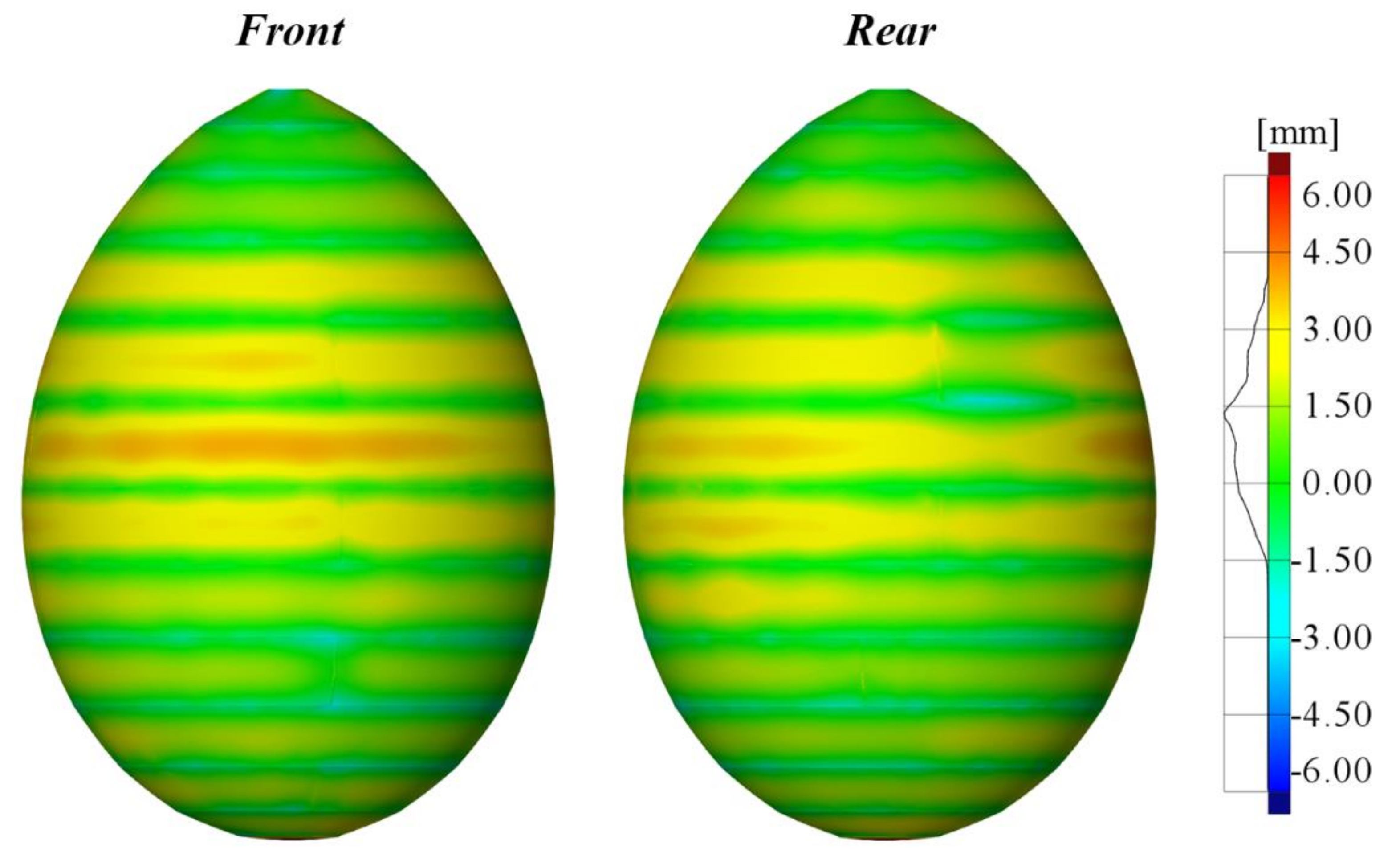
Figure 8.
Shape deviations of the hydroformed eggshell from the designed geometry. Negative values indicate outward deformation of the hydroformed eggshell.
Figure 8.
Shape deviations of the hydroformed eggshell from the designed geometry. Negative values indicate outward deformation of the hydroformed eggshell.

Figure 9.
Analytical yield load profile of the stepped preform and eggshell.
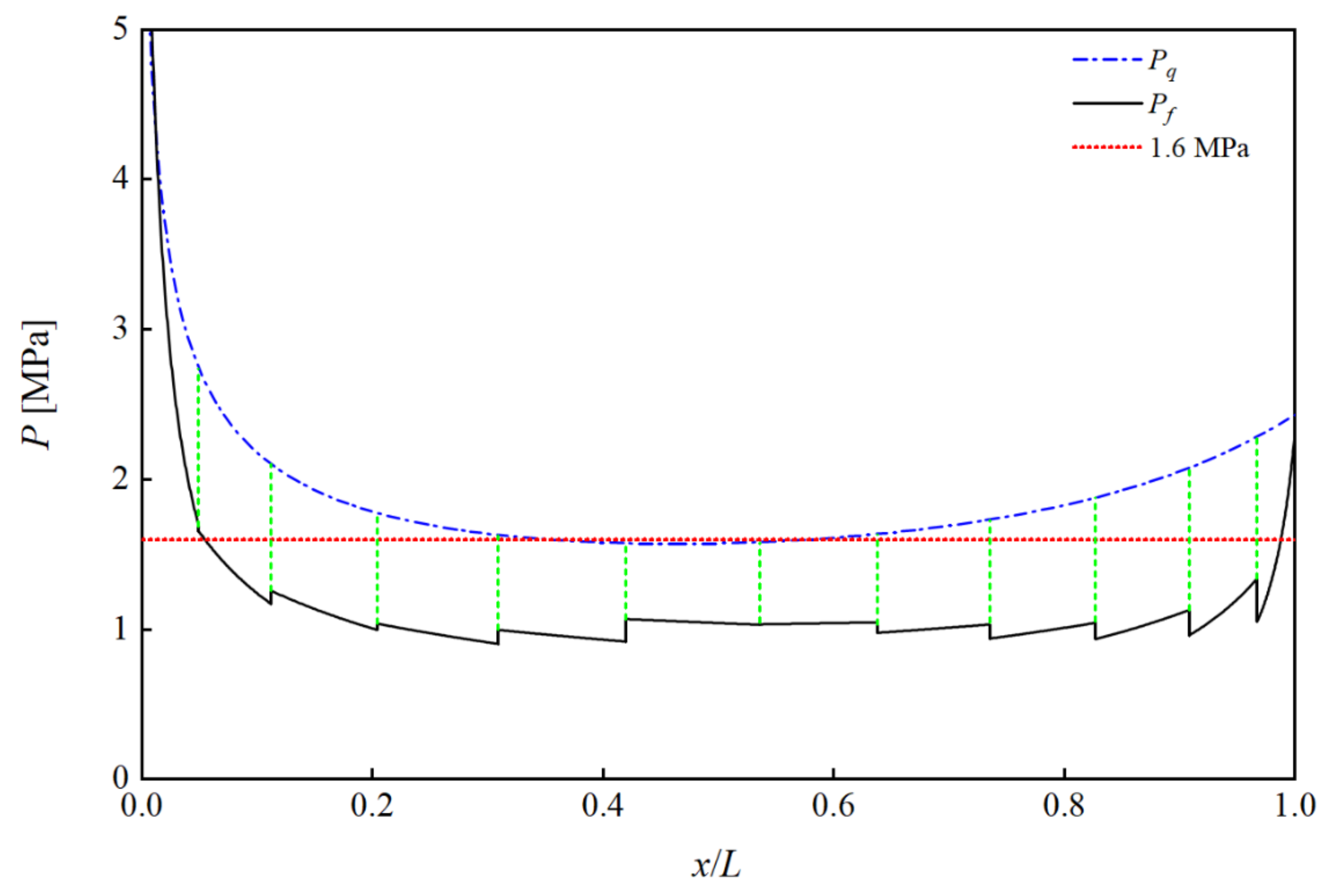
Figure 10.
Analytically and numerically derived stress distributions of the hydroformed eggshell.
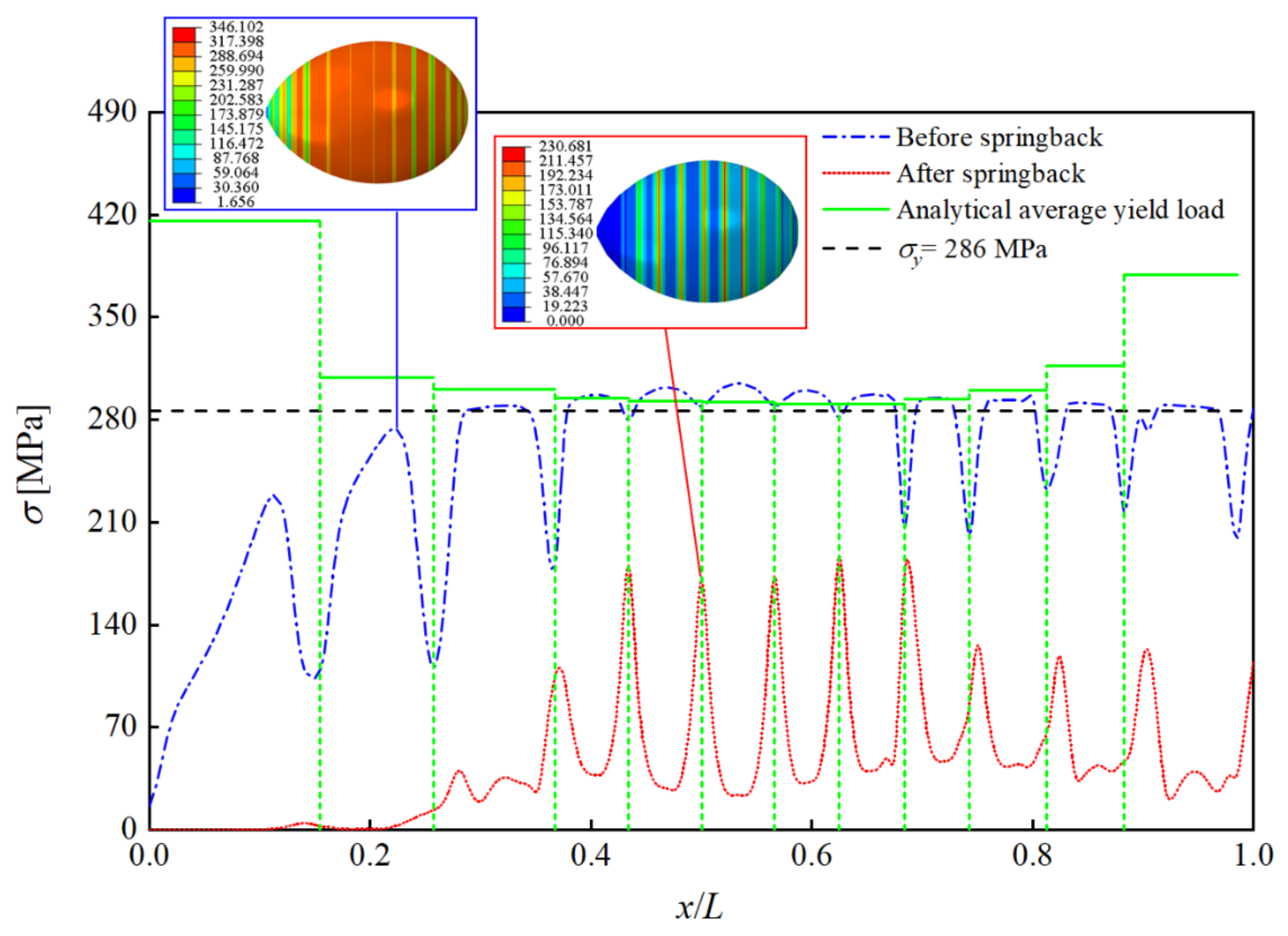
Figure 11.
Finite-element model of eggshell hydroforming.
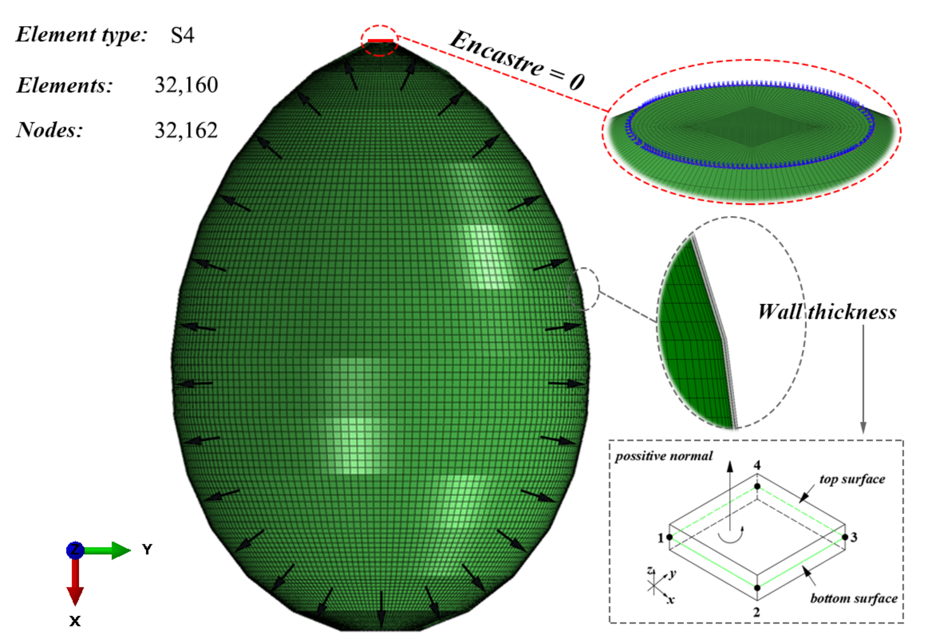
Figure 12.
Mesh sensibility test of eggshell hydroforming.

Figure 13.
Comparison of the numerical and experimental external shapes.
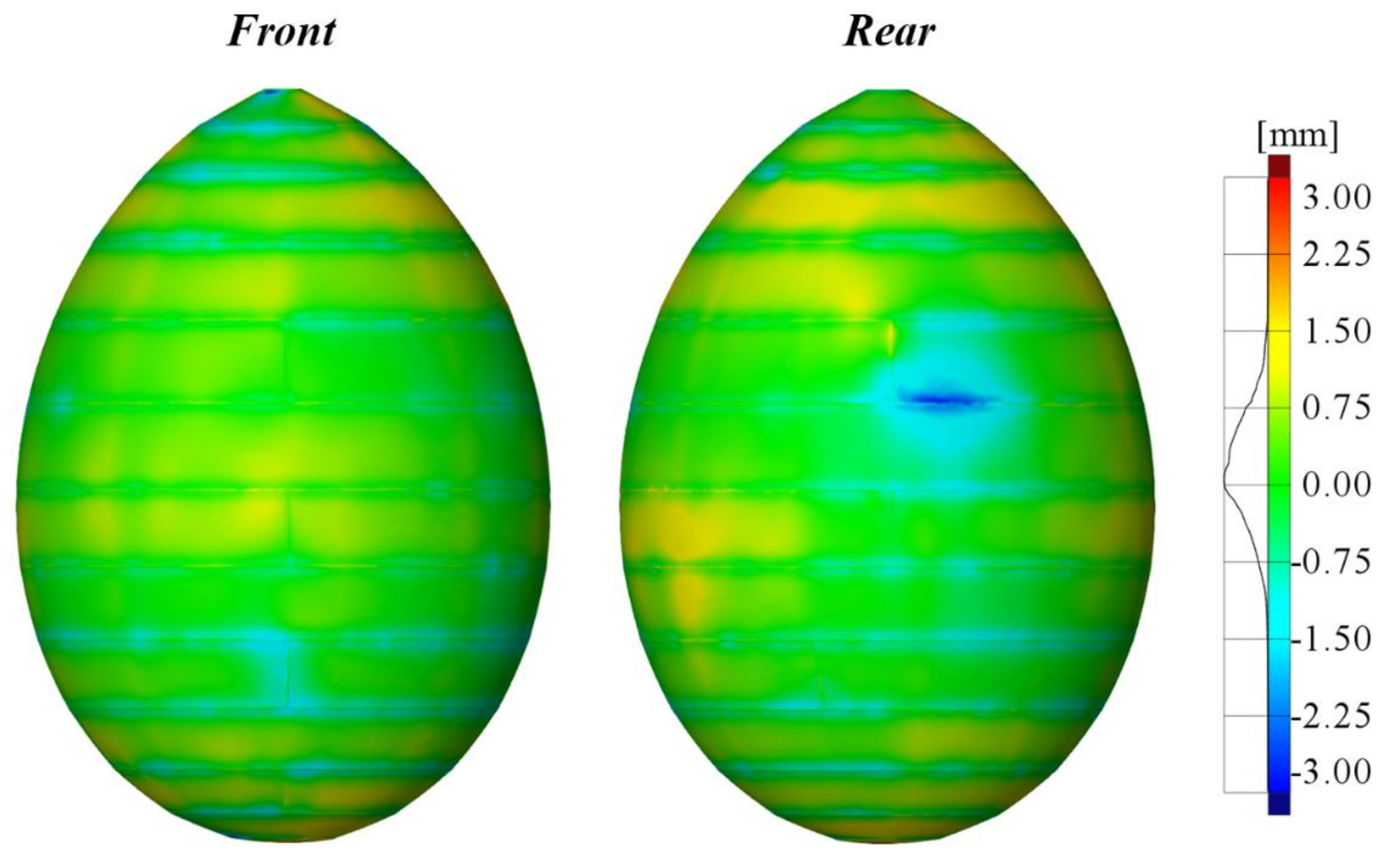
Figure 14.
Displacement of the hydroformed eggshell before and after springback.

Figure 15.
Comparison of the numerical and experimental wall thickness.
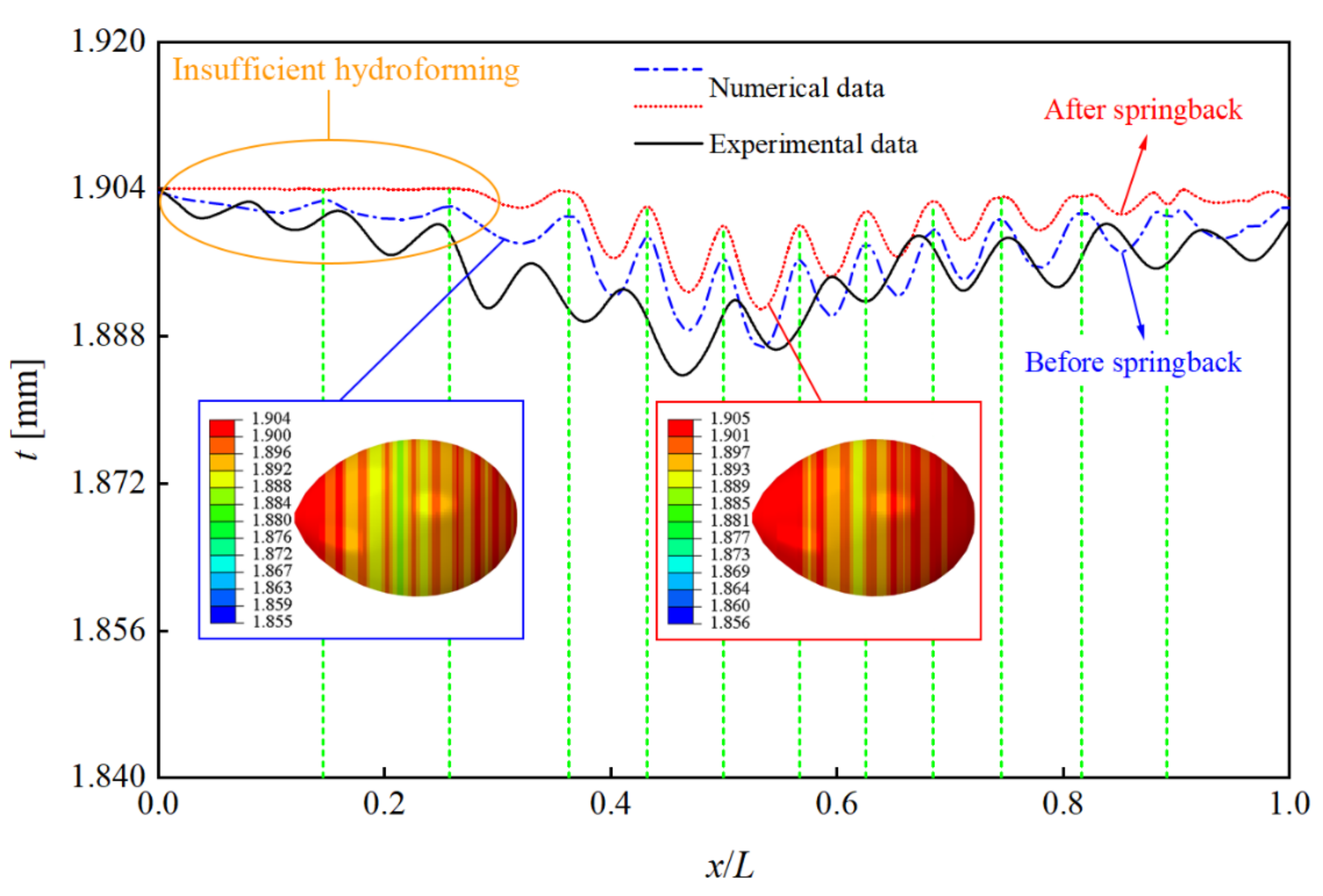
Figure 16.
Finite-element model of the circular beam elements.

Figure 17.
Changes in the parameters of hydroformed eggshells without and with circular weld lines (R = 4 mm) versus internal pressure: (a) axial height, (b) maximum wall thinning, (c) closed capacity, and (d) surface area.
Figure 17.
Changes in the parameters of hydroformed eggshells without and with circular weld lines (R = 4 mm) versus internal pressure: (a) axial height, (b) maximum wall thinning, (c) closed capacity, and (d) surface area.
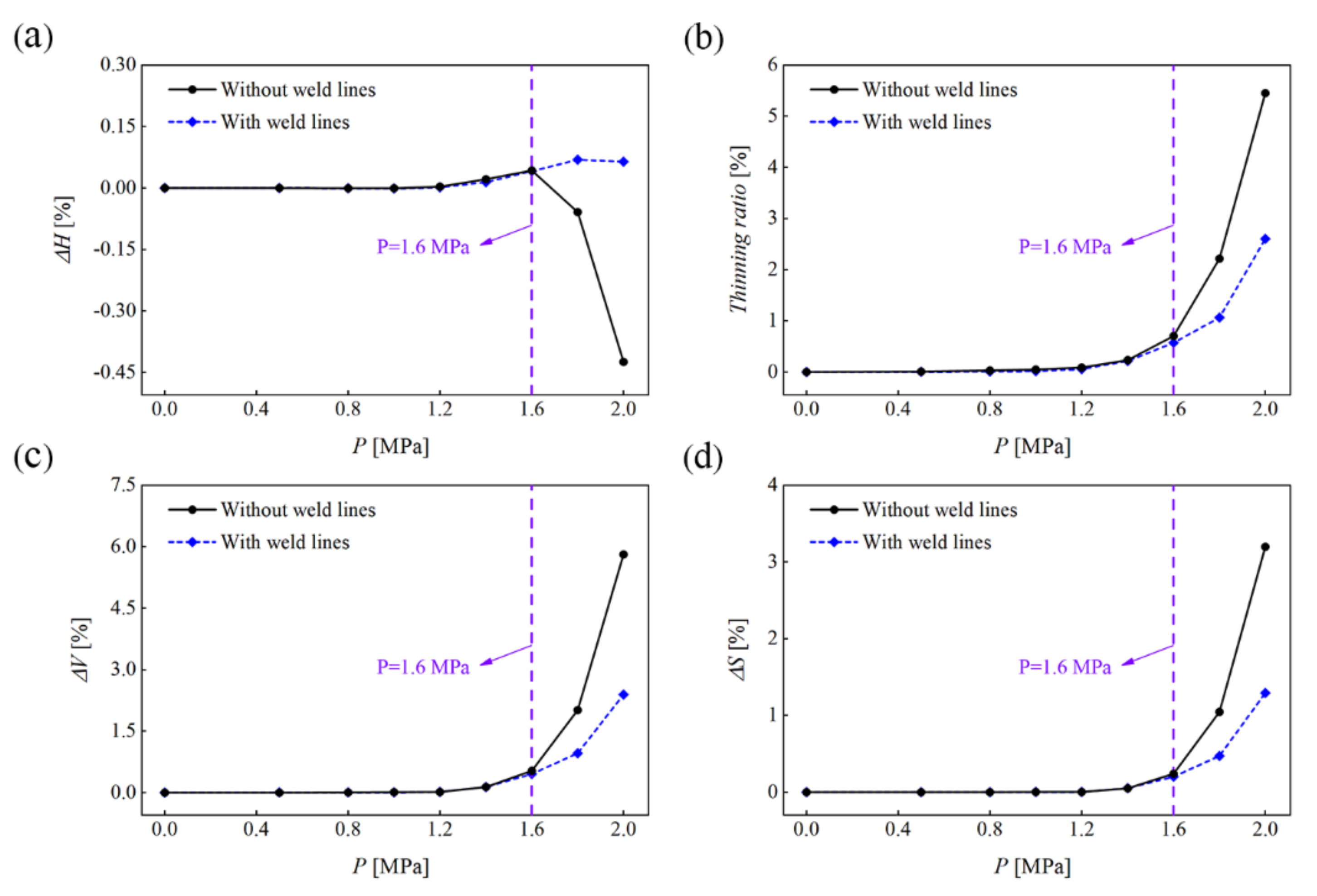
Figure 18.
Geometric deviation of hydroformed eggshells with weld lines (R = 4 mm) from those without weld lines. Negative values indicate outward hydroforming of the shells with weld lines.
Figure 18.
Geometric deviation of hydroformed eggshells with weld lines (R = 4 mm) from those without weld lines. Negative values indicate outward hydroforming of the shells with weld lines.

Table 1.
Parameters of each conical segment equation for the designed stepped preform.
| Segment | ki | bi (mm) |
|---|---|---|
| 1st | 1.84 | 33.51 |
| 2nd | 1.11 | 88.39 |
| 3rd | 0.76 | 146.7 |
| 4th | 0.51 | 225.96 |
| 5th | 0.31 | 320.97 |
| 6th | 0.13 | 437.5 |
| 7th | −0.05 | 578.8 |
| 8th | −0.23 | 752.2 |
| 9th | −0.45 | 995.77 |
| 10th | −0.76 | 1385.99 |
| 11th | −1.29 | 2116.03 |
| 12th | −2.51 | 3909.19 |
Table 2.
Nominal dimensions of the designed stepped preform and eggshell.
| Parameters | Values (mm) |
|---|---|
| Minor axis of eggshell (B) | 1070 |
| Major axis of eggshell (L) | 1537 |
| Wall thickness of stepped preform (t) | 1.9 |
| Height of thick closure (T) | 10 |
| Diameter of thick closure (d) | 67 |
| Hole diameter (Φ) | 20 |
| Pole sheet diameter (D) | 206 |
| Meridian length of 1st segment of stepped preform (L1) | 157.3 |
| Meridian length of 2nd segment of stepped preform (L2) | 140.8 |
| Meridian length of 3rd segment of stepped preform (L3) | 176.8 |
| Meridian length of 4th segment of stepped preform (L4) | 179.0 |
| Meridian length of 5th segment of stepped preform (L5) | 176.2 |
| Meridian length of 6th segment of stepped preform (L6) | 176.5 |
| Meridian length of 7th segment of stepped preform (L7) | 155.1 |
| Meridian length of 8th segment of stepped preform (L8) | 152.0 |
| Meridian length of 9th segment of stepped preform (L9) | 152.4 |
| Meridian length of 10th segment of stepped preform (L10) | 154.9 |
| Meridian length of 11th segment of stepped preform (L11) | 145.9 |
| Meridian length of 12th segment of stepped preform (L12) | 133.6 |
Table 3.
Geometric parameters determined analytically for each conical segment before and after hydroforming.
Table 3.
Geometric parameters determined analytically for each conical segment before and after hydroforming.
| Segment | Si0 (mm2) | Si1 (mm2) | Vi0 (mm3) | Vi1 (mm3) | Hi (mm) |
|---|---|---|---|---|---|
| 1st | 101,435 | 103,814 | 2,857,513 | 3,278,619 | 75.05 |
| 2nd | 198,271 | 199,794 | 15,125,846 | 15,547,038 | 94.16 |
| 3rd | 366,836 | 369,852 | 48,490,680 | 49,519,885 | 140.30 |
| 4th | 477,599 | 480,859 | 90,600,147 | 91,862,411 | 159.37 |
| 5th | 543,926 | 547,259 | 127,829,647 | 129,203,572 | 168.35 |
| 6th | 585,752 | 589,415 | 153,553,684 | 155,094,384 | 175.08 |
| 7th | 521,791 | 524,534 | 139,565,774 | 140,706,599 | 154.88 |
| 8th | 491,609 | 494,457 | 123,468,732 | 124,612,009 | 148.15 |
| 9th | 447,171 | 450,316 | 95,529,255 | 96,722,333 | 139.17 |
| 10th | 378,675 | 382,145 | 59,089,901 | 60,310,434 | 123.46 |
| 11th | 261,032 | 263,730 | 23,190,990 | 24,065,192 | 89.49 |
| 12th | 138,611 | 140,049 | 4,493,564 | 4,929,671 | 49.47 |
Table 4.
Mechanical parameters of each conical segment determined analytically from the elastic–plastic hardening model.
Table 4.
Mechanical parameters of each conical segment determined analytically from the elastic–plastic hardening model.
| Segment | εt | εθ | εφ | εeq | σy (MPa) |
|---|---|---|---|---|---|
| 1st | −0.0232 | 0.0689 | −0.0456 | 0.0997 | 416 |
| 2nd | −0.0077 | 0.0137 | −0.0061 | 0.0176 | 309 |
| 3rd | −0.0082 | 0.0105 | −0.0023 | 0.0118 | 301 |
| 4th | −0.0068 | 0.0069 | −0.0001 | 0.0070 | 295 |
| 5th | −0.0061 | 0.0053 | 0.0008 | 0.0050 | 293 |
| 6th | −0.0062 | 0.0050 | 0.0012 | 0.0045 | 292 |
| 7th | −0.0052 | 0.0041 | 0.0012 | 0.0036 | 291 |
| 8th | −0.0058 | 0.0046 | 0.0012 | 0.0041 | 291 |
| 9th | −0.0070 | 0.0062 | 0.0008 | 0.0058 | 294 |
| 10th | −0.0091 | 0.0102 | −0.0011 | 0.0108 | 300 |
| 11th | −0.0103 | 0.0185 | −0.0082 | 0.0237 | 317 |
| 12th | −0.0103 | 0.0463 | −0.0360 | 0.0715 | 379 |
Disclaimer/Publisher’s Note: The statements, opinions and data contained in all publications are solely those of the individual author(s) and contributor(s) and not of MDPI and/or the editor(s). MDPI and/or the editor(s) disclaim responsibility for any injury to people or property resulting from any ideas, methods, instructions or products referred to in the content. |
© 2023 by the authors. Licensee MDPI, Basel, Switzerland. This article is an open access article distributed under the terms and conditions of the Creative Commons Attribution (CC BY) license (https://creativecommons.org/licenses/by/4.0/).
Share and Cite
MDPI and ACS Style
Tang, Y.; Zhang, J.; Zhan, M.; Jiao, H.; Cheng, P.; Dai, M. Internal Hydroforming of Large Stainless-Steel Eggshells from Stepped Preforms. Metals 2023, 13, 1352. https://doi.org/10.3390/met13081352
AMA Style
Tang Y, Zhang J, Zhan M, Jiao H, Cheng P, Dai M. Internal Hydroforming of Large Stainless-Steel Eggshells from Stepped Preforms. Metals. 2023; 13(8):1352. https://doi.org/10.3390/met13081352
Chicago/Turabian StyleTang, Yinhui, Jian Zhang, Ming Zhan, Huifeng Jiao, Peng Cheng, and Mingqiang Dai. 2023. "Internal Hydroforming of Large Stainless-Steel Eggshells from Stepped Preforms" Metals 13, no. 8: 1352. https://doi.org/10.3390/met13081352
Note that from the first issue of 2016, this journal uses article numbers instead of page numbers. See further details here.