Article

Functionally Graded Additive Manufacturing of Thin-Walled 316L Stainless Steel-Inconel 625 by Direct Laser Metal Deposition Process: Characterization and Evaluation

by
Omid Mehrabi
1,
Seyed Mohammad Hossein Seyedkashi
1,* and
Mahmoud Moradi
2,*
1
Department of Mechanical Engineering, University of Birjand, Birjand 97175-376, Iran
2
Faculty of Arts, Science and Technology, University of Northampton, Northampton NN1 5PH, UK
*
Authors to whom correspondence should be addressed.
Metals 2023, 13(6), 1108; https://doi.org/10.3390/met13061108
Submission received: 13 April 2023 / Revised: 3 June 2023 / Accepted: 9 June 2023 / Published: 12 June 2023
(This article belongs to the Special Issue Laser-Based Additive Manufacturing of Metals and Alloys)

Abstract

:
Direct Laser Metal Deposition (DLMD) is a state-of-the-art manufacturing technology used to fabricate 316L stainless steel/Inconel 625 functionally graded material (FGMs) in this research. For the practical application of these materials in the industry, the effects of process parameters on the geometric characteristics and surface roughness require more investigation. This FGM was additively manufactured in five layers by changing the 316L stainless steel/Inconel 625 ratio in each layer. The effects of laser power on geometric characteristics, height stability, and surface roughness were investigated. The microstructural analysis and microhardness profiles were studied. The results show that despite the high solidification rate, the segregation of alloying elements into dendritic areas occurred. It was also found that increasing the laser power will increase the height, width, height stability, and surface roughness of the gradient walls. The maximum width and height of the deposited layers were 1.615 and 6.42 mm, respectively, at the highest laser power (280 W). At the laser power of 220 W, the least surface roughness (Ra = 105 µm) and the best height stability (0.461 mm) will be obtained. The microhardness values will differ in various sections of the gradient walls in a range of 225–277 HV.

1. Introduction

Functionally graded materials (FGMs) are a group of advanced engineering materials. The composition and structure of their constituent materials gradually vary over volume [1]. The purpose of the fabrication of FGMs is to eliminate sudden changes and create a smooth transition from one material to another [2]. Additive manufacturing is one of the appropriate methods for the fabrication of FGMs [3].
Additive manufacturing is a production method of three-dimensional parts from a digital model by placing layers of materials on each other. This unique feature allows the fabrication of complex geometries, as well as special-purpose designs directly by reducing the manufacturing steps required in traditional construction methods. All these advantages explain the reason for the widespread attention to this method of fabrication in various industries [4]. Directed Energy Deposition (DED) is an additive manufacturing method that uses an energy source, such as a laser beam, an electron beam, or a plasma arc to melt a material [5]. Direct Laser Metal Deposition (DLMD) is a type of DED process for the fabrication of metallic components. Direct laser metal deposition is performed by simultaneously spraying the metal powders under concentrated laser energy. Figure 1 shows a schematic of this process. The DLMD process uses a continuous or pulsed wave laser to create a melt pool on the substrate, and the raw material powder is injected into the melt pool by a powder spraying nozzle. Layers are formed as a result of the solidification of the melt pool, and the product is made layer by layer on the substrate [6,7].
In research conducted by Yu et al. [8], the effect of the Cr/Mo ratio on the mechanical properties and weldability of four nickel-based superalloys in the additive manufacturing process was investigated. The results showed that by decreasing the Cr/Mo ratio, the inter-dendritic phases evolved from lath and eutectic Laves phases to blocky P phases. The P phase can degrade ductility and increase both hardness and strength due to solid-solution strengthening. The effect of process parameters on the additive manufacturing of 316L/SiCp metal matrix composite was investigated using different weight percentages of 316L and SiCp powders by the direct laser deposition method by Riquelme et al. [9]. The results showed that increasing the weight percentage of SiCp reduces the microhardness.
Sahasrabudhe et al. [10] investigated the bimetal stainless steel-titanium structure fabricated by laser-engineered net shaping (LENS). Zhang and Bandyopadhyay [11] studied the direct fabrication of functionally graded Ti-Al2O3 using laser-engineered net shaping. The functionally graded composites consisted of different parts: i.e., Ti6Al4V alloy, Ti6Al4V + Al2O3 composites, and pure Al2O3 ceramic. The hardness measurements showed that the pure Al2O3 part demonstrated the greatest hardness. Ahsan et al. [12] studied the microstructures and mechanical behavior of bimetallic additively manufactured structures of stainless steel and Inconel 625. They sequentially deposited austenitic stainless steel and Inconel 625 using gas metal arc welding (GMAW). The results revealed that both materials were face-centered cubic (FCC) austenite, and the hardness values were in the range of 220 to 240 HV for both materials without a large deviation at the interface. The effect of process parameters on bead geometries of SS316L fabricated by wire–arc additive manufacturing method was investigated by Chaudhari et al. [13].
FGMs of steel and Inconel are nowadays one of the most widely used high-performance engineering materials. In recent years, studies have been carried out on their fabrication using additive manufacturing methods [14,15]. High-performance engineering materials could be used for industrial applications, including gas turbines, power plants, and aerospace [16]. These materials must be strong, hard, and economically feasible. For these purposes, SS316L is an intriguing material. Expensive materials such as Inconel 625 should be utilized as a coating on SS316L to enhance its qualities, such as corrosion resistance and strength [14,15]. This combination of properties and economic considerations could lead to the extension of the fabrication of SS316L-Inconel 625 FGMs. Feenstra et al. [17] investigated the effect of input energy density on the growth of the interface of SS316L/Inconel 625 and its mechanical properties by changing the laser power. Moreover, Chen et al. [15] studied the fabrication of SS316L and Inconel 625 functionally graded materials by laser direct metal deposition. Sargent et al. [18] investigated the powder-based DED to find novel alloys by mixing SS316L with Inconel 718. Ferreira et al. [19] fabricated the Inconel 625/AISI 431 steel bulk material using the DED process. Kim et al. [20] investigated the microstructure, defect behavior, and microhardness of the Inconel 718-SS316L FGM fabricated by DED. They showed that in the faulty range, few segregants were produced in the interdendritic areas, and more precipitates were created near the grain boundaries. As another example, Senthil et al. [21] fabricated Inconel 825-SS316L FGM and investigated the microstructure and mechanical properties of the samples. They demonstrated that the microstructure of the Inconel 825 had a cellular-dendritic structure, and the microstructure of the SS316L was composed of austenite and 5% delta ferrite. Li et al. [22] investigated the mechanical and microstructural characterization of Inconel 625-SS308L FGM fabricated by additive manufacturing. Li et al. [23] investigated the microhardness, phase, oxidation, and microstructure of laminated composites of Inconel 718 and SS316L fabricated by additive manufacturing. Savitha et al. [24] investigated the characterization, microstructure, and mechanical properties of SS316L/Inconel 625 FGMs fabricated by LENS. In a study by Melzer et al. [25], the microstructure and mechanical properties of SS316L-Inconel 718 FGM built by DED were investigated.
In most previous studies, the microstructure and mechanical properties of Inconel 625/SS316L FGMs were investigated, while the effects of the laser power on their geometrical characteristics and surface roughness were studied to a lesser extent. Therefore, in this research, the effects of laser power on the width, height, surface roughness, and height stability of the Inconel 625/SS316L FGMs walls manufactured by the DLMD method were investigated. The additive manufacturing of thin-walled SS316L-Inconel 625 FGM was performed by the DLMD method using a 1000 W continuous-wave fiber laser. The thin-walled SS316L-Inconel 625 FGM was fabricated in five layers while changing the SS316L/Inconel 625 ratio in each layer. The microhardness and the microstructure of the gradient walls were also investigated by optical microscopy (OM) and scanning electron microscopy (SEM).

2. Materials and Methods

The purpose of this study is to fabricate the thin-walled SS316L-Inconel 625 FGM by direct laser metal deposition. In the following, the used powders, devices, experiments, and characterization methods will be mentioned.

2.1. Materials

In this study, Inconel 625 and 316L stainless steel powders with spherical morphologies (as shown in Figure 2) were used with an average particle size of 45 and 110 μm, respectively. AISI 4130 austenitic steel was used as the substrate. Table 1 presents the chemical composition of the materials. Before the DLMD process, AISI 4130 steel was ground using magnetic grinding to make the substrate smooth, followed by washing it in suds. Finally, it was cleaned using alcohol (with a purity of 96%).

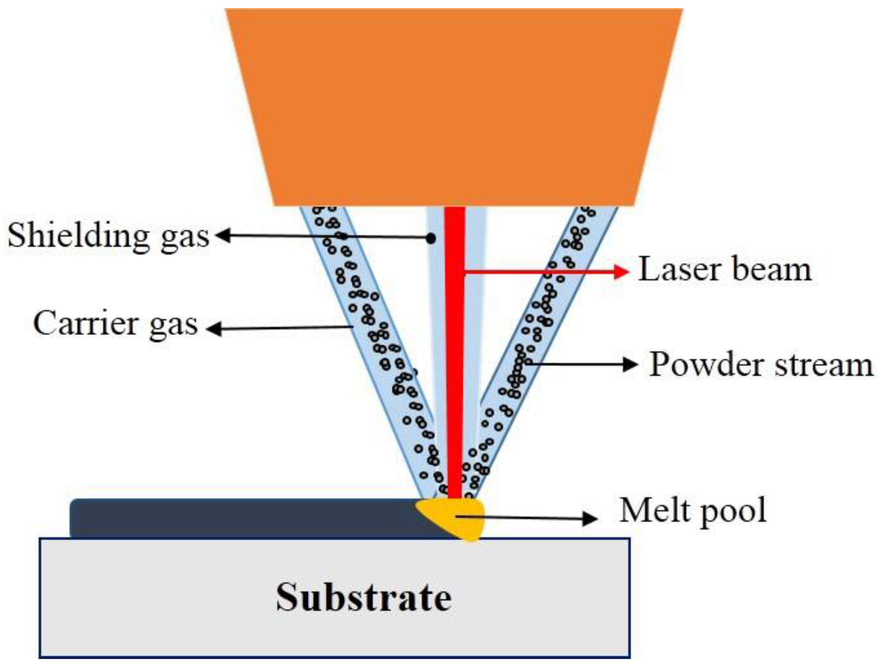
2.2. Direct Laser Metal Deposition Process

The DLMD system device was equipped with a 1 KW continuous-wave fiber laser YFL-1000 model (National Laser Center, Tehran, Iran) with a wavelength of 1080 nm, a four-channel brass nozzle to deliver powders coaxial with the laser beam, a powder feeder with two separate containers, a carrier, and shielding argon gas, and a computer numerical control (CNC) table. Figure 3 depicts the schematic diagram of the DLMD system used in this study, and Table 2 shows the constant process parameters.
Before the process begins, SS316L and Inconel 625 powders are loaded separately into the feeder containers, and the rotation speed of the powder feeder discs is independently adjusted during the process. Using Argon carrier gas, the necessary weight percentage of each alloy to deposit each layer, according to Table 3, is delivered to the powder mixing chamber. After homogenization, the powder combination is fed into the melt pool through four channels implanted in the nozzle head. Based on the authors’ previous work [26,27], the dwell time for each deposited layer was 20 s. In addition, the substrate moved 0.3 mm down to add the next layer to the previously deposited layer to maintain the focal distance of the laser beam and the powder flow. The layering in these studies was done in a one-way direction.
Direct laser metal deposition of the thin-walled SS316L-Inconel 625 FGM was carried out in five layers, where the weight percentage of Inconel and steel was different in each layer, according to Table 3. Primary experiments were performed in different percentages of the powder blending to determine the appropriate range of mixing these two powders. A length of 2 cm on the AISI 4130 steel substrate was deposited. Three gradient walls were fabricated through DLMD by changing the laser power according to Table 4 under the constant process parameters, as shown in Table 2. Also, the method of calculating the laser energy density is expressed as Equation (1) [28], where E (J/mm2) is the laser energy density, P (W) is the laser power, V (mm/s) is the laser scanning speed, and D (mm) is the laser beam diameter. Figure 4 shows the fabricated gradient walls.
E = P V × D

2.3. Characterization

To study the microstructure and geometric characteristics of the gradient walls, they were cut in half using a wire electrical discharge machining (EDM) machine. After cutting the samples, surface preparation (cold mounting, grinding, and polishing) was performed and the gradient walls were etched for 25 to 30 s in the Marble solution; HCl 37% (50 mL) + CuSO4 (10 gr) + H2O (50 mL).
Images with different magnifications were taken from the cross-sectional area of the samples using the HUVITZ HR3-TRF-P optical microscope (Huvitz, Gyeonggi-do, Republic of Korea). Then, the height (H) and width (W) of the layers were measured according to the schematic illustrated in Figure 5 using the ImageJ software. The widths of five layers were measured to report the width of the walls, and the average value was reported. Scanned electron microscopy images with different magnifications were also recorded by the FESEM QUANTA 200 scanning electron microscope (Quanta, Hillsboro, OR, USA) to analyze and study the microstructure of the gradient walls.
The surface roughness of the gradient walls was measured with an accuracy of 4 μm using a laser surface profilometer LPM-D1 model (Kahreba technology, Tehran, Iran). This device uses laser triangulation technology to study the surfaces of objects. The distances of the objects from the sensor are, therefore, determined by combining the laser, the optical system, and a charge-coupled device (CCD) sensor. The device software is designed so that the data acquisition is performed according to the selected step. The sample moves in one direction on the stage, and the sensor moves perpendicular to the sample on the other stage. The combination of these two movements can scan the specimen’s surface and measure the surface roughness [29]. To measure the surface smoothness of each sample, a 50-µm step in two directions with a length of 8 mm and a width of 4 mm was used, and the average surface roughness (Ra) was reported.
To evaluate the height stability of the gradient walls, the length of the deposited layers is divided into three regions: the beginning, middle, and end of the deposit. The maximum and minimum heights are measured in these three areas. The difference between the maximum and minimum heights is calculated, and the highest value is reported as “dimensional stability” [30]. Figure 6 shows the schematic illustration of how dimensional stability is studied. Also, the method of calculating the surface dimensional stability of the samples is expressed as Equations (2)–(5) [30].
h 1 = H M a x 1 H M i n 1
h 2 = H M a x 2 H M i n 2
h 3 = H M a x 3 H M i n 3
H = M a x { h 1 , h 2 , h 3 }
The Vickers microhardness along the deposited layer with an average distance of 500 μm between indentations was measured according to the ASTM E384 standard [31] using a MICROMET BUEHLER device (Buehler, Leinfelden-Echterdingen, Germany). A load of 300 gf was applied for 15 s to create an indentation on the deposited layer.

3. Results and Discussion

The additive manufacturing of the SS316L-Inconel 625 gradient walls was successfully performed by direct laser metal deposition. The microstructure of gradient walls was examined. In addition, the effect of laser power on the width, height, surface roughness, microhardness, and height stability of the gradient walls was studied.

3.1. Microstructural Analysis

The SEM images in Figure 7 and Figure 8 show the appropriate deposition of layers on each other by the DLMD method. The equilibrium microstructure of SS316L is austenitic, but depending on the alloy composition and the solidification path, the microstructure can change based on the developed phase diagrams. The final microstructure of Inconel 625 consists of austenite γ and Laves phases [32], as shown in Figure 8.
The four simple types of S/L interface (S: solid phase, L: liquid phase) that can be seen during the solidification in the gradient walls are planar, cellular, columnar dendritic, and equiaxed dendritic (see Figure 7 and Figure 8). Figure 7 is an optical microscopic image with a magnification of 200× from the cross-section of the gradient wall, which also shows the interfaces of different layers. Figure 8 shows the SEM images of different points on the cross-sectional area of the gradient wall.
Due to the low-temperature gradient and high growth rate, the main morphology of the gradient walls is columnar dendritic and equiaxed dendritic. The high solidification rate of the DLMD process results in the formation of a dendritic microstructure. The difference in the solidification type due to the presence of different alloying elements–especially those with the equilibrium partition coefficients of less than one, such as molybdenum and niobium–caused the microstructure to become dendritic. The secondary phases were formed in the inter-dendritic regions. This dendritic structure was formed along the temperature gradients caused by the high cooling rate due to direct laser metal deposition [33]. The resultant structure in this part can be justified by Equation (6) [34].
G R Δ T D L
Δ T D L = m L C s ( 1 K 0 ) K 0 D L
where G is the temperature gradient, D L the solute diffusivity in the liquid phase, m L the slope of the liquidus line, C s the solid chemical composition at the interface, K 0 the equilibrium partition coefficient, and R the growth rate. According to the equation, a stable form of planar growth can be deduced. This equation indicates that dendritic growth will occur when the G / R ratio is less than T / D L . Moreover, it implies that the lower the gradient and the higher the growth rate, the greater the possibility of dendritic solidification will be. On the other hand, the high solidification temperature range T and the low diffusion coefficient D L result in dendritic and cellular solidification. Therefore, solidification in the gradient walls started as columnar dendritic and equiaxed dendritic in the microstructure, and the growth occurred in the direction of temperature gradients. Figure 7 and Figure 8 show the columnar and equiaxed dendritic solidification in different layers of the gradient walls. According to Equation (6), equiaxed and columnar dendritic structures were formed because the temperature gradient was low and the growth rate was high in the walls [34].
As shown in Figure 7 and Figure 8, during the solidification, the grains tend to grow perpendicular to the boundary of the melt pool owing to the presence of the highest temperature gradient and, consequently, the highest heat output in this direction. However, columnar dendrites and cells within each grain tend to grow in the easy growth direction. For Inconel and steel with face-centered cubic (FCC) structures, the easy growth direction is <1 0 0>, in which the dendrites grow [16]. This mechanism is called competitive growth. Therefore, during the solidification, the grains whose easy growth direction is perpendicular to the melt pool boundary grow more easily, and the grains that are not properly oriented leave the competition. The SEM image in Figure 8 of the interface layers deposited shows an acceptable connection between the layers, and the walls had the fewest welding defects, such as cracks and pores. The microstructure is discontinuous at the interface of layers. The interface width between layers depends on factors such as laser energy density and dwell time. Also, it is obvious from these images that the changed areas are the interface regions of the layers. Since the previously solidified layers undergo laser reheating during the layer-by-layer deposition of materials on the substrate, the growth of the dendrites occurs by reheating when the next layer is fabricated. As a result, the grain size at the interface of the layers and nearby regions increases.
As can be seen in Figure 8, planar solidification is observed at the substrate/first layer interface (Figure 8a). The reason for this change is that the highest temperature gradient due to heat accumulation is in the substrate near the interface of the first layer and the substrate [16]. Due to the heat absorption of the substrate and its lower temperature, the cooling rate near the substrate is higher. The substrate thus works as a cold sink absorbing the heat from the deposited layer. It causes the formation of planar solidification at the substrate/first layer interface. As the distance from the substrate surface increases, the solidification mode changes into a dendritic structure in other parts of the gradient wall.
Figure 9 shows the accumulation and segregation of both Niobium (Nb) and Molybdenum (Mo) at the boundary of dendrites. The presence of these alloying elements in the interdendritic regions could lead to the formation of precipitates and continuous intermetallic phases such as niobium carbide and molybdenum carbide between the dendrites. It should also be noted that a higher concentration of Nb leads to the formation of Laves phase.
Several defects may exist in additively manufactured specimens, including porosity, open pores, and shrinkage cavities. The most common defects that might occur during this process are porosity and unmelted powders. The closed and open pores are depicted as black spots in Figure 10. Many factors, such as laser power, scan speed, powder feed rate, shielding gas flow pressure, and powder quality, can cause the formation of porosity in additively manufactured specimens [35]. Common porosity defects can be categorized as a lack of fusion (LOF) and gas pores [36]. The lack of fusion of pores usually occurs at the interface of the layers as a result of low laser energy density (low laser power, high scanning speed) and high powder deposition density (like Figure 10c,d). The gas pores are usually induced by entrapped powder particles, molten pool surface fluctuations, and hydrogen-related porosity [36]. Additionally, during powder feeding, gas porosity may be caused by moisture or gas that has adhered to the surface of the powders [36,37]. During the deposited process, moisture and hydrogen—likely originating from wetness and other hydrocarbon compounds on the surface of the powder—can react with metal elements in the melt pool to produce extra hydrogen. This extra hydrogen can cause the formation of porosity [36,38].
It is clear that the porosity can be round (like Figure 10a,b) or interdendritic (like Figure 10d). It is not always easy to identify whether interdendritic pores are caused by gas or solidification shrinkage [39]. If they are created because of gas, they must have occurred during the latter stages of solidification, when the dendritic structure has been largely formed. Therefore, in order to make additively manufactured samples with the least microstructure defects, process parameter optimization, suitable powder quality, and post-processing treatment are needed.

3.2. Geometry

Comparing the geometric dimensions (average width and height) of the layers deposited in the three samples shown in Figure 11 shows, the height and the average width of the walls increased with increasing the laser power. The temperature also increases by increasing the laser power, causing the deposition of a larger volume of the powder sprayed into the melt pool on the substrate and preventing the powder from spreading around after leaving the spraying nozzle. As a result, the layer formed on the substrate gains a higher height and greater width after the molten powder solidifies. This change can be proved according to the laser energy density in Equation (1) [28]. Since the laser velocity and beam diameter are kept constant, the laser energy density increases with the increase of the laser power [40]. Hence, more powder particles will melt, and the melt pool becomes larger. The larger melt pool creates a layer with greater width and height. Kim et al. [41] claim that the dimensions (width and height) of the melt pool rise with the laser power. This rise occurs due to the fact that with high laser power, the density of the laser energy is higher. Subsequently, the amount of energy absorption by the powder particle will be higher, leading to a greater powder melting and deposition ratio [30,42]. These results are in agreement with other studies [43,44,45].
The laser energy density for samples #1, #2, and #3 was 38.86, 44.16, and 49.46 J/mm2, respectively. The maximum height and width of the gradient walls belonged to sample #3 with a laser power of 280 W. In this sample, the laser energy density was 49.46 J/mm2, according to Equation (1). The melt pool was enlarged, compared to other samples, as a result of increasing the height and width of this wall owing to the utilization of maximum laser energy density.

3.3. Height Stability

According to Figure 6, the largest and smallest heights and their differences in each region ( Δ h = maximum peak to valley height) were calculated for the samples. Among the differences calculated for each sample, the largest difference was selected as the stability of the samples ( Δ H = m a x ( h i ) ). The results are given in Table 5. The maximum height stability of the walls (0.608 mm) was obtained at a laser power of 280 W (sample #3), while the best height stability (0.461 mm) was obtained at a laser power of 220 W (sample #1).
Figure 12 shows that the increase in power increases the value of Δh, which is in accordance with other studies [26,27]. This is because by increasing the laser power, the laser energy density increased, and a larger melt pool was created. This increased the height and width of the layers, in turn. As a result, the height between peaks and valleys at the surface of the walls became taller and the stability decreased. Therefore, the surface distortion increased and the surface quality decreased. On the other hand, a rise in laser power will enlarge the melt pool. The melting pool becomes more unstable as it expands. This increase in the instability of the melt pool causes the formation of deposited layers with more distortion [46]. As a result, the height stability of the samples will rise.

3.4. Surface Roughness

In direct laser metal deposition, the laser powder is sprayed simultaneously along the laser path. It causes inefficiency of powder melting in the process, which leads to a lower surface smoothness. The roughness (Ra) of the lateral surface of the gradient walls was measured using a laser profilometer. Figure 13 shows that the surface roughness of the samples increased with increasing the laser power. The best surface smoothness (Ra = 105 µm) belonged to sample #1 with a laser power of 220 W. As mentioned in the previous section, increasing the laser power increased the laser beam density according to Equation (1), which resulted in a larger melt pool causing an increase in the width and height of the deposited layer. Deposition of the larger layers on each other creates larger peak-to-valley distances on the lateral surface of the walls, increasing the surface roughness. In sample #1, the height and width of the layers were smaller than those of other samples decreasing the surface roughness. As mentioned above, increasing the laser power will increase the dimensions of the melt pool (width and height). Increasing the size of the melt pool will cause the formation of larger layers [47], and as shown in other studies [48], large layers will increase the surface roughness. Also, with the rise in laser power, the instability of the melt pool rises, increasing the surface roughness [40,46]. Figure 14 shows the topography of the lateral surface of the gradient wall. As can be seen in the figures, the largest peak-to-valley distance (0.89 mm) belonged to sample #3 with a laser power of 280 W, while the smallest amount was equal to 0.64 mm with a laser power of 220 W. This increase in the maximum peak-to-valley height increased the surface roughness of the gradient wall.

3.5. Vickers Microhardness (HV) Profile

The microhardness of the samples was measured by the Vickers method according to the ASTM E384 standard alongside the deposited layer at 12 points with an average distance of 500 µm, as shown in Figure 15a. The hardness profile of the gradient walls is presented in Figure 15b. Since the cooling rate of the molten Inconel and steel after the DLMD process is not the same in all parts of the sample, the value of microhardness is different in various parts of the gradient walls. Several factors such as solidification type, grain size, dendrite size, and segregation of the elements can affect the microhardness values [49]. The range of microhardness variation at different points of the gradient wall was between 225 and 277 Vickers, which is similar to what is seen in the literature [50,51]. The average microhardness for samples #1, #2, and #3 was 242, 244, and 241 HV, respectively.
The highest microhardness value in the samples was achieved at the points close to the substrate. Since the substrate acted as a heat sink, the cooling rate and temperature gradient were higher near the substrate than at other points along the gradient wall. Hence, smaller grain sizes and dendrites were obtained. On the other hand, the lower temperature gradient led to the grains and dendrites growing, becoming coarser, and increasing the segregation of elements. These factors decreased the microhardness in the last layer of the gradient walls. During the fabrication of each layer of the gradient wall, the laser heat input acted like heat treatment, affecting the material microstructure, grain growth, and hardness. In the points where the grains were finer and the inter-dendritic space was smaller, the value of microhardness was higher. The grains were also reheated due to the heat input applied by the laser in the next layer near the layers’ interfaces. Consequently, the grains and dendrites grew and became coarser, reducing the microhardness in these regions.
Another major reason for the microhardness reduction could be the high fraction of Niobium-enriched regions, which led to niobium reduction in the γ-matrix. Niobium is one of the most important elements in γ-matrix precipitates, which are the main source to strengthen the Inconel. The Niobium-enriched regions reduced the hardness of the deposited samples [52].
An additional reason for the hardness changes could be that a large amount of the Laves phase was present in the interdendritic regions of the γ-matrix of Niobium and Molybdenum. The reduction of Niobium and Molybdenum in the γ-matrix reduced the solid–solution strengthening, which led to the softening of the γ-matrix and reduced the microhardness values [53].

4. Conclusions

The additive manufacturing of the steel-Inconel gradient wall was performed successfully by the DLMD method. The microstructure of the gradient walls was surveyed through OM and SEM. Also, the effect of laser power on the width, height, surface roughness, microhardness, and height stability of the gradient walls was studied. The following conclusions can be drawn:
(1)
Due to the relatively high cooling rate and low-temperature gradients in the DLMD process, the main solidification morphology of the samples was in three forms: cellular, equiaxed dendritic, and columnar dendritic. Based on this justification and the results of the elemental analysis, it can be concluded that despite the high solidification rate in laser deposition, the segregation of alloying elements into interdendritic regions will still occur.
(2)
The increase in the laser power will increase the laser energy density, thus increasing the height and width of the gradient walls.
(3)
The increase in the laser power reduces both the height stability and the surface smoothness of the gradient walls. The best height stability and surface smoothness were observed in sample #1, which were 461 and 105 µm, respectively.
(4)
Because the cooling rates of Inconel and steel after additive manufacturing were not the same in all regions of the sample, the microhardness values were different at various points on the gradient walls. Several factors, such as the solidification type, the size of dendrites, and the segregation of the elements, could affect the microhardness values. The range of the microhardness variation in the gradient walls was between 225 HV to 277 HV.
It was finally determined that the direct laser deposition method is one of the suitable methods for the fabrication of SS316L-Inconel 625 FGM samples with different desired chemical compositions. The chemical composition of materials in each layer can be easily changed during this process. In order to obtain SS316L-Inconel 625 FGM samples without microstructural and mechanical defects, however, a more detailed understanding of the process is needed, as well as optimization of other process parameters, such as scanning speed, size of the powders, focal point position, dwell time, etc.

Author Contributions

Conceptualization, methodology, writing—original draft, visualization, O.M.; project administration, supervision, validation, writing,—review and editing, S.M.H.S.; co-supervision, methodology, resources, writing—review and editing, M.M. All authors have read and agreed to the published version of the manuscript.

Funding

This research did not receive any specific grant from funding agencies in the public, commercial, or not-for-profit sectors.

Data Availability Statement

The data presented in this study are available on request from the corresponding author.

Conflicts of Interest

The authors declare no conflict of interest.

References

  1. Zhang, C.; Chen, F.; Huang, Z.; Jia, M.; Chen, G.; Ye, Y.; Lin, Y.; Liu, W.; Chen, B.; Shen, Q.; et al. Additive manufacturing of functionally graded materials: A review. Mater. Sci. Eng. A 2019, 764, 138209. [Google Scholar] [CrossRef]
  2. Naebe, M.; Shirvanimoghaddam, K. Functionally graded materials: A review of fabrication and properties. Appl. Mater. Today 2016, 5, 223–245. [Google Scholar] [CrossRef]
  3. Ghanavati, R.; Naffakh-Moosavy, H. Additive manufacturing of functionally graded metallic materials: A review of experimental and numerical studies. J. Mater. Res. Technol. 2021, 13, 1628–1664. [Google Scholar] [CrossRef]
  4. DebRoy, T.; Wei, H.L.; Zuback, J.S.; Mukherjee, T.; Elmer, J.W.; Milewski, J.O.; Beese, A.M.; Wilson-Heid, A.; De, A.; Zhang, W. Additive manufacturing of metallic components—Process, structure and properties. Prog. Mater. Sci. 2018, 92, 112–224. [Google Scholar] [CrossRef]
  5. Svetlizky, D.; Das, M.; Zheng, B.; Vyatskikh, A.L.; Bose, S.; Bandyopadhyay, A.; Schoenung, J.M.; Lavernia, E.J.; Eliaz, N. Directed energy deposition (DED) additive manufacturing: Physical characteristics, defects, challenges and applications. Mater. Today 2021, 49, 271–295. [Google Scholar] [CrossRef]
  6. Sibisi, P.N.; Popoola, A.P.I.; Arthur, N.K.K.; Pityana, S.L. Review on direct metal laser deposition manufacturing technology for the Ti-6Al-4V alloy. Int. J. Adv. Manuf. Technol. 2020, 107, 1163–1178. [Google Scholar] [CrossRef]
  7. Sobhanieh, N.; Akbari, J.; Moradi, M. A new method for calculating laser intensity distribution on workpiece surface in laser-directed energy deposition process by considering powder stream distribution and laser attenuation. Int. J. Adv. Manuf. Technol. 2022, 121, 337–348. [Google Scholar] [CrossRef]
  8. Yu, Q.; Wang, C.; Yang, G.; Ren, Y.; Liu, N.; Liang, Y.; Dong, C. Influence of Cr/Mo ratio on microstructure and mechanical properties of the Ni-based superalloys fabricated by laser additive manufacturing. J. Alloys Compd. 2022, 894, 162484. [Google Scholar] [CrossRef]
  9. Riquelme, A.; de Rojas Candela, C.S.; Rodrigo, P.; Rams, J. Influence of process parameters in additive manufacturing of highly reinforced 316L / SiCp composites. J. Mater. Process. Technol. 2022, 299, 117325. [Google Scholar] [CrossRef]
  10. Sahasrabudhe, H.; Harrison, R.; Carpenter, C.; Bandyopadhyay, A. Stainless steel to titanium bimetallic structure using LENS™. Addit. Manuf. 2015, 5, 1–8. [Google Scholar] [CrossRef]
  11. Zhang, Y.; Bandyopadhyay, A. Direct fabrication of compositionally graded Ti-Al2O3 multi-material structures using Laser Engineered Net Shaping. Addit. Manuf. 2018, 21, 104–111. [Google Scholar] [CrossRef]
  12. Ahsan, R.; Fan, X.; Seo, G.-J.; Ji, C.; Noakes, M.; Nycz, A.; Liaw, P.K.; Kim, D.B. Microstructures and mechanical behavior of the bimetallic additively-manufactured structure (BAMS) of austenitic stainless steel and Inconel 625. J. Mater. Sci. Technol. 2021, 74, 176–188. [Google Scholar] [CrossRef]
  13. Chaudhari, R.; Parmar, H.; Vora, J.; Patel, V.K. Parametric study and investigations of bead geometries of GMAW-based Wire arc additive manufacturing of 316L stainless steels. Metals 2022, 12, 1232. [Google Scholar] [CrossRef]
  14. Tong, X.; Lu, C.; Huang, Z.; Zhang, C.; Chen, F. Microstructures and mechanical properties of crack-free 316L stainless steel and Inconel 625 joint by using Laser Engineered Net Shaping. Opt. Laser Technol. 2022, 155, 108357. [Google Scholar] [CrossRef]
  15. Chen, B.; Su, Y.; Xie, Z.; Tan, C.; Feng, J. Development and characterization of 316L/Inconel625 functionally graded material fabricated by laser direct metal deposition. Opt. Laser Technol. 2020, 123, 105916. [Google Scholar] [CrossRef]
  16. Ghanavati, R.; Naffakh-Moosavy, H.; Moradi, M. Additive manufacturing of thin-walled SS316L-IN718 functionally graded materials by direct laser metal deposition. J. Mater. Res. Technol. 2021, 15, 2673–2685. [Google Scholar] [CrossRef]
  17. Feenstra, D.R.; Molotnikov, A.; Birbilis, N. Effect of energy density on the interface evolution of stainless steel 316L deposited upon INC 625 via directed energy deposition. J. Mater. Sci. 2020, 55, 13314–13328. [Google Scholar] [CrossRef]
  18. Sargent, N.; Wang, Y.; Li, D.; Zhao, Y.; Wang, X.; Xiong, W. Exploring alloy design pathway through directed energy deposition of powder mixtures: A study of Stainless Steel 316L and Inconel 718. Addit. Manuf. Lett. 2023, 6, 100133. [Google Scholar] [CrossRef]
  19. Ferreira, A.A.; Emadinia, O.; Amaral, R.L.; Cruz, J.M.; Reis, A.R.; Vieira, M.F. Mechanical and microstructural characterisation of Inconel 625–AISI 431 steel bulk produced by direct laser deposition. J. Mater. Process. Technol. 2022, 306, 117603. [Google Scholar] [CrossRef]
  20. Kim, S.H.; Lee, H.; Yeon, S.M.; Aranas, C.; Choi, K.; Yoon, J.; Yang, S.W.; Lee, H. Selective compositional range exclusion via directed energy deposition to produce a defect-free Inconel 718/SS 316L functionally graded material. Addit. Manuf. 2021, 47, 102288. [Google Scholar] [CrossRef]
  21. Senthil, T.S.; Puviyarasan, M.; Babu, S.R.; Senthil, S. Mechanical characterization of wire arc additive manufactured and cast Inconel 825: A comparative study. Mater. Today Proc. 2022, 62, 973–976. [Google Scholar] [CrossRef]
  22. Li, T.; Wang, Z.; Yang, Z.; Shu, X.; Xu, J.; Wang, Y.; Hu, S. Fabrication and characterization of stainless steel 308 L/Inconel 625 functionally graded material with continuous change in composition by dual-wire arc additive manufacturing. J. Alloys Compd. 2022, 915, 165398. [Google Scholar] [CrossRef]
  23. Li, P.; Zhou, J.; Li, L.; Gong, Y.; Lu, J.; Meng, X.; Zhang, T. Influence of depositing sequence and materials on interfacial characteristics and mechanical properties of laminated composites. Mater. Sci. Eng. A 2021, 827, 142092. [Google Scholar] [CrossRef]
  24. Savitha, U.; Reddy, G.J.; Venkataramana, A.; Rao, A.S.; Gokhale, A.A.; Sundararaman, M. Chemical analysis, structure and mechanical properties of discrete and compositionally graded SS316–IN625 dual materials. Mater. Sci. Eng. A 2015, 647, 344–352. [Google Scholar] [CrossRef]
  25. Melzer, D.; Džugan, J.; Koukolíková, M.; Rzepa, S.; Vavřík, J. Structural integrity and mechanical properties of the functionally graded material based on 316L/IN718 processed by DED technology. Mater. Sci. Eng. A 2021, 811, 141038. [Google Scholar] [CrossRef]
  26. Moradi, M.; Ashoori, A.; Hasani, A. Additive manufacturing of stellite 6 superalloy by direct laser metal deposition—Part 1: Effects of laser power and focal plane position. Opt. Laser Technol. 2020, 131, 106328. [Google Scholar] [CrossRef]
  27. Moradi, M.; Hasani, A.; Beiranvand, Z.M.; Ashoori, A. Additive manufacturing of stellite 6 superalloy by direct laser metal deposition—Part 2: Effects of scanning pattern and laser power reduction in differrent layers. Opt. Laser Technol. 2020, 131, 106455. [Google Scholar] [CrossRef]
  28. Olakanmi, E.O.; Sepako, M.; Morake, J.; Hoosain, S.E.; Pityana, S.L. Microstructural characteristics, crack frequency and diffusion kinetics of functionally graded Ti-Al composite coatings: Effects of Laser Energy Density (LED). J. Miner. Met. Mater. Soc. 2019, 71, 900–911. [Google Scholar] [CrossRef]
  29. Mitaľ, G.; Dobránsky, J.; Ružbarský, J.; Olejárová, Š. Application of laser profilometry to evaluation of the surface of the workpiece machined by abrasive waterjet technology. Appl. Sci. 2019, 9, 2134. [Google Scholar] [CrossRef] [Green Version]
  30. Moradi, M.; Hasani, A.; Pourmand, Z.; Lawrence, J. Direct laser metal deposition additive manufacturing of Inconel 718 superalloy: Statistical modelling and optimization by design of experiments. Opt. Laser Technol. 2021, 144, 107380. [Google Scholar] [CrossRef]
  31. Hetzner, D.W. Microindentation hardness testing of materials using ASTM E384. Microsc. Microanal. 2003, 9, 708–709. [Google Scholar] [CrossRef] [Green Version]
  32. Lippold, J.C.; Kiser, S.D.; DuPont, J.N. Welding Metallurgy and Weldability of Nickel-Base Alloys; John Wiley & Sons: Hoboken, NJ, USA, 2011. [Google Scholar]
  33. Lippold, J.C. Welding Metallurgy Principles. In Welding Metallurgy and Weldability; John Wiley & Sons: Hoboken, NJ, USA, 2015; pp. 9–83. [Google Scholar]
  34. Kou, S. Basic Solidification Concepts. In Welding Metallurgy, 2nd ed.; John Wiley & Sons, Inc.: Hoboken, NJ, USA, 2002; pp. 143–169. [Google Scholar]
  35. Kasperovich, G.; Haubrich, J.; Gussone, J.; Requena, G. Correlation between porosity and processing parameters in TiAl6V4 produced by selective laser melting. Mater. Des. 2016, 105, 160–170. [Google Scholar] [CrossRef] [Green Version]
  36. Wang, S.; Ning, J.; Zhu, L.; Yang, Z.; Yan, W.; Dun, Y.; Xue, P.; Xu, P.; Bose, S.; Bandyopadhyay, A. Role of porosity defects in metal 3D printing: Formation mechanisms, impacts on properties and mitigation strategies. Mater. Today 2022, 59, 133–160. [Google Scholar] [CrossRef]
  37. Gould, B.; Wolff, S.; Parab, N.; Zhao, C.; Lorenzo-Martin, M.C.; Fezzaa, K.; Greco, A.; Sun, T. In Situ Analysis of Laser Powder Bed Fusion Using Simultaneous High-Speed Infrared and X-ray Imaging. JOM 2021, 73, 201–211. [Google Scholar] [CrossRef]
  38. Wu, B.; Pan, Z.; Ding, D.; Cuiuri, D.; Li, H.; Xu, J.; Norrish, J. A review of the wire arc additive manufacturing of metals: Properties, defects and quality improvement. J. Manuf. Process. 2018, 35, 127–139. [Google Scholar] [CrossRef]
  39. Kou, S. Weld Metal Chemical Inhomogeneities. In Welding Metallurgy; John Wiley & Sons, Inc.: Hoboken, NJ, USA, 2002; pp. 243–262. [Google Scholar]
  40. Zhang, T.; Yuan, L. Understanding surface roughness on vertical surfaces of 316 L stainless steel in laser powder bed fusion additive manufacturing. Powder Technol. 2022, 411, 117957. [Google Scholar] [CrossRef]
  41. Kim, M.J.; Saldana, C. Thin wall deposition of IN625 using directed energy deposition. J. Manuf. Process. 2020, 56, 1366–1373. [Google Scholar] [CrossRef]
  42. Moradi, M.; Pourmand, Z.; Hasani, A.; Moghadam, M.K.; Sakhaei, A.H.; Shafiee, M.; Lawrence, J. Direct laser metal deposition (DLMD) additive manufacturing (AM) of Inconel 718 superalloy: Elemental, microstructural and physical properties evaluation. Optik 2022, 259, 169018. [Google Scholar] [CrossRef]
  43. Wu, B.; Pan, Z.; Ding, D.; Cuiuri, D.; Li, H.; Xu, J.; Norrish, J. Effects of laser processing parameters on microstructure and mechanical properties of additively manufactured AlSi10Mg alloys reinforced by TiC. Int. J. Adv. Manuf. Technol. 2019, 103, 3235–3246. [Google Scholar]
  44. Nankali, M.; Akbari, J.; Moradi, M.; Beiranvand, Z.M. Effect of laser additive manufacturing parameters on hardness and geometry of Inconel 625 parts manufactured by direct laser metal deposition. Optik 2022, 249, 168193. [Google Scholar] [CrossRef]
  45. Vora, J.; Parikh, N.; Chaudhari, R.; Patel, V.K.; Paramar, H.; Pimenov, D.Y.; Giasin, K. Optimization of bead morphology for GMAW-based wire arc additive manufacturing of 2.25 Cr-1.0 Mo steel using metal-cored wires. Appl. Sci. 2022, 12, 5060. [Google Scholar] [CrossRef]
  46. Skalon, M.; Meier, B.; Gruberbauer, A.; Amancio-Filho, S.D.T.; Sommitsch, C. Stability of a melt pool during 3D-printing of an unsupported steel component and its influence on roughness. Materials 2020, 13, 808. [Google Scholar] [CrossRef] [PubMed] [Green Version]
  47. Zhang, J.; Shi, S.; Fu, G.; Shi, J.; Zhu, G.; Cheng, D. Analysis on surface finish of thin-wall parts by laser metal deposition with annular beam. Opt. Laser Technol. 2019, 119, 105605. [Google Scholar] [CrossRef]
  48. Alimardani, M.; Fallah, V.; Iravani-Tabrizipour, M.; Khajepour, A. Surface finish in laser solid freeform fabrication of an AISI 303L stainless steel thin wall. J. Mater. Process. Technol. 2012, 212, 113–119. [Google Scholar] [CrossRef]
  49. Chen, W.; Yin, G.; Feng, Z.; Liao, X. Effect of powder feedstock on microstructure and mechanical properties of the 316L stainless Steel fabricated by selective laser melting. Metals 2018, 8, 729. [Google Scholar] [CrossRef] [Green Version]
  50. Kurzynowski, T.; Gruber, K.; Stopyra, W.; Kuźnicka, B.; Chlebus, E. Correlation between process parameters, microstructure and properties of 316 L stainless steel processed by selective laser melting. Mater. Sci. Eng. A 2018, 718, 64–73. [Google Scholar] [CrossRef]
  51. Liverani, E.; Toschi, S.; Ceschini, L.; Fortunato, A. Effect of selective laser melting (SLM) process parameters on microstructure and mechanical properties of 316L austenitic stainless steel. J. Mater. Process. Technol. 2017, 249, 255–263. [Google Scholar] [CrossRef]
  52. Kumar, M.B.; Sathiya, P.; Kannan, G.R.; Karthikeyan, M. Investigation on the microstructure and microhardness of Inconel 825 thick wall fabricated by wire arc additive manufacturing. Mater. Lett. 2022, 317, 132115. [Google Scholar] [CrossRef]
  53. Zhang, W.; Liu, F.; Liu, F.; Huang, C.; Liu, L.; Zheng, Y.; Lin, X. Effect of Al content on microstructure and microhardness of Inconel 718 superalloy fabricated by laser additive manufacturing. J. Mater. Res. Technol. 2022, 16, 1832–1845. [Google Scholar] [CrossRef]
Figure 1. Schematic of the direct laser metal deposition process.
Metals 13 01108 g001
Figure 2. SEM image of powders; (a) SS316L, (b) Inconel 625.
Metals 13 01108 g002
Figure 3. Schematic diagram of direct laser metal deposition system.
Metals 13 01108 g003
Figure 4. Additively manufactured samples by DLMD method, #1 laser power 220 W, #2 laser power 250 W, #3 laser power 280 W.
Metals 13 01108 g004
Figure 5. Geometrical features of a sample cross-section.
Metals 13 01108 g005
Figure 6. Schematic of calculating the height stability.
Metals 13 01108 g006
Figure 7. Evolution of microstructure along the cross–section of sample #1, from (a) layer 1, (b) interface of layers 1 and 2, (c) layer 2, (e) interface of layers 2 and 3, (f) interface of layers 3 and 4, (g) interface of layers 4 and 5.
Metals 13 01108 g007
Figure 8. The SEM micrographs along the cross-section of sample #3 from (a) interface of the substrate and layer 1, (b) interface of layers 1 and 2, (c) interface of layers 2 and 3, (d) interface of layers 3 and 4, (e) interface of layers 4 and 5, (f) layer 3.
Metals 13 01108 g008
Figure 9. (a) The chemical analysis results of the EDS spot points; (a) image of layer 4 of sample #3 (25%SS 316L + 75% Inconel 625), (b) EDS analysis of spot 1, (c) EDS analysis of spot 2, (d) EDS analysis of spot 3.
Metals 13 01108 g009
Figure 10. Defects in the microstructure of sample #1 from (a) layer 1 (100%SS 316L), (b) layer 2 (75%SS 316L + 25% Inconel 625), (c) interface of layers 1 and 2 (100%SS 316L + to 50%SS 316L + 50% Inconel 625), (d) interface of layers 2 and 3 (75%SS 316L + 25% Inconel 625 to 50%SS 316L + 50% Inconel 625).
Metals 13 01108 g010
Figure 11. Effect of the laser power on (a) average width and (b) height.
Metals 13 01108 g011
Figure 12. Effect of the laser power on height stability.
Metals 13 01108 g012
Figure 13. Effect of the laser power on surface roughness.
Metals 13 01108 g013
Figure 14. (a) 3D reconstructions of the surface topography; (b) sample #1, (c) sample #2; (d) sample #3.
Metals 13 01108 g014
Figure 15. (a) Microhardness measured points on the macrostructure of sample #3, (b) Microhardness profile along the cross-section of samples #1, #2, and #3.
Metals 13 01108 g015
Table 1. Chemical composition of SS316 and Inconel 625 powders and the substrate.
MaterialElement (wt.%)FeNiNbMoSiMnCrSPCCu
PowdersInconel 6251.46Base2.696.830.650.5522.45--0.02-
SS 316LBase125.620.51.5180.010.020.020.23
SubstrateAISI 4130Base0.05-0.250.30.871.010.030.0160.250.06
Table 2. The constant DLMD processing parameters.
ParameterScanning Speed (mm/min)Focal Point Position (mm)Axial Gas Flow (L/min)Carrier Gas Flow (L/min)Beam Diameter (mm)Standoff Distance (mm)Scan Pattern
Value170−233215Metals 13 01108 i001
Table 3. The adjusted Powder flow rate for each layer of the samples.
Layer Number (Layers)Powder Flow Rate (g/min)
Feeder (1) SS 316LFeeder (2) Inconel 625
Layer 1 (%100 SS316L)230
Layer 2 (%75 SS 316L + %25 Inconel 625)17.255.75
Layer 3 (%50 SS 316L + %50 Inconel 625)11.511.5
Layer 4 (%25 SS 316L + %75 Inconel 625)5.7517.25
Layer 5 (%100 Inconel 625)2323
Table 4. The DLMD processing parameter in the samples.
Sample No.Power (w)Laser Energy Density (J/mm2)
Sample #122038.86
Sample #225044.16
Sample #328049.46
Table 5. The maximum and minimum heights and their differences in three regions (beginning, middle, and end of samples).
No. H M i n 1
(mm)
H M a x 1
(mm)
H M i n 2
(mm)
H M a x 2
(mm)
H M i n 3
(mm)
H M a x 3
(mm)
h 1
(mm)
h 2
(mm)
h 3
(mm)
H
Sample #15.8636.2915.6005.9315.9426.4030.4280.3310.4610.461
Sample #25.9556.2345.8316.3426.1946.2010.2790.5110.0170.511
Sample #35.9996.3626.2776.6386.2456.8530.3630.3610.6080.608
Disclaimer/Publisher’s Note: The statements, opinions and data contained in all publications are solely those of the individual author(s) and contributor(s) and not of MDPI and/or the editor(s). MDPI and/or the editor(s) disclaim responsibility for any injury to people or property resulting from any ideas, methods, instructions or products referred to in the content.

