
Two-Phase Flow Coordination Characteristics of H62 Brass Alloy Prepared by Up-Drawing Continuous Casting
by
Bing Li
1,2,*,
Qianqian Fu
1,3,
Rongzhou Yu
1,2,
Zikai Lin
1,
Jun Wang
1,
Xue Wang
1,
Renguo Guan
1,2 and
Jiehua Li
4,* 1
Engineering Research Center of Continuous Extrusion, Dalian Jiaotong University, Ministry of Education, Dalian 116028, China
2
Key Laboratory of Near-Net Forming of Light Metals of Liaoning Province, Dalian Jiaotong University, Dalian 116028, China
3
College of Mechanical and Electrical Engineering, Shanxi Datong University, Datong 037009, China
4
Institute of Casting Research, Montanuniversität Leoben, A-8700 Leoben, Austria
*
Authors to whom correspondence should be addressed.
Metals 2023, 13(3), 599; https://doi.org/10.3390/met13030599
Submission received: 10 February 2023
/
Revised: 1 March 2023
/
Accepted: 7 March 2023
/
Published: 15 March 2023
(This article belongs to the Special Issue Grain Refinement and Mechanical Properties of Cast Alloys)
Abstract
:In this study, the two-phase flow coordination characteristics between α and β phases of H62 brass made by up-drawing continuous casting are investigated based on the upsetting process. An in situ and new research method for two-phase flow is put forward, and the two-phase flow and grain refinement characteristics are observed under different deformation conditions. The results show that α phase flows fast under 400 °C, β phase is pulled and overridden by α phase under this temperature. When the temperature increases to 500 °C, which is higher than β phase transition temperature, the flow velocity of β phase increases, and the deformation of β phase is found to bulge. The flow of β phase is more sensitive to low deformation rates than α phase. The deformation amount has a more significant impact on β phase than α phase, and the deformation of β phase promotes the grain fragmentation and refinement of α phase accompanied by huge β phase bulging obviously. Under the conditions of high temperature, low deformation rate, and large deformation amount, both phase α and β of up-drawing continuous casting brass alloy are broken and the grains are refined. Based on the two-phase flow characteristic, numerical simulation is used to obtain the optimal continuous extrusion parameters of the H-shaped wire of up-drawing continuous casting H62 brass. Then, the optimized complex cross-section wire is prepared by continuous extrusion experiment. This research aims to provide guidance for the complex processing of two-phase alloys.
1. Introduction
H62 brass alloy is widely applied in electrical contacting products due to its excellent formability and smooth surface [1,2,3]. However, H62 brass alloy is two-phase brass with α + β phase, and the flow of the two phases is different significantly during the plastic forming process, which affects the forming stability of H62 brass [4,5,6]. Neishi et al. investigated the severe plastic deformation of Cu-40%Zn alloy and Cu-Zn-Sn alloy [7,8]. In terms of the influence of thermal deformation and heat treatment on the microstructure evolution of two-phase brass, Lee et al. investigated the effect of thermal deformation processing on the grain boundary of two-phase brass [9]. Kim et al. investigated the performance of heat treatment of duplex brass after equal channel extrusion [10]. The microstructure evolution of two-phase brass alloy has an important influence on the product properties. In terms of the microstructure evolution of the Cu-Zn alloy, Subramanya et al. investigated the microstructure and mechanical properties of the Cu-Zn alloy [11]. Cai et al. investigated the nanotwinned microstructures from low stacking fault energy brass by high–rate severe plastic deformation [12]. Xiao et al. investigated the microstructures and mechanical properties of Cu-Zn alloy under dynamic plastic deformation [13]. Rohini et al. investigated the texture and microstructure evolution of two-phase brass alloys after rolling [14]. Peng et al. investigated the equivalent strain, microstructure, and hardness evolution of two-phase brass alloy deformed by constrained groove pressing [15]. The flow characteristics of each phase in two-phase brass under deformation conditions have a significant impact on the microstructure and properties. In terms of grain refinement of α and β phase, Xiao et al. developed the constitutive model under the condition of hot compression and investigated the transformation condition of α and β phase [16]. The hot deformation behavior and microstructure of H62 brass alloys were also investigated. The flow and refining conditions of each phase in two-phase brass are important research contents. However, few studies have been completed to analyze the flow forming characteristics of two phases of H62 brass during the forming process. Therefore, the purpose of this paper is to elucidate the flow coordination relationship of α and β phase of H62 brass during the forming process.
Based on the upsetting forming process, the flow coordination characteristics of H62 brass alloy were investigated. An in situ new method to analyze two-phase flow was proposed, which is beneficial for observing the difference in the microstructure before and after the deformation process. Two-phase flow and grain refinement characteristics of H62 brass were investigated under the different conditions of deformation temperature, deformation rate, and deformation amount. The two-phase flow law of brass is intended to serve as a theoretical guide for the complex processing of H62 brass. The numerical simulation was carried out and the optimum results were obtained based on upsetting laws. Process parameters provided by numerical simulation were applied in the experiment of continuous extrusion of H-shaped wire of H62 brass alloy.
2. Materials and Methods
Up-drawing continuous casting H62 brass rod (manufactured by Boway Alloy Co., Ltd., Ningbo, China) was adopted as an initial material. The H62 brass rod was composed of 62.5% Cu, Fe 0.15%, 0.01% P, 0.002% Bi, and balance zinc (mass fraction). To achieve a contrast microstructure observation of H62 brass before and after compression, the side faces of the up-drawing continuous casting rod with a diameter of 8 mm were cut with a height of 6.5 mm, and the cross-section was a 7 × 7 mm square with four round corners radius of 4 mm. The cross-sections ensure that the initial and final microstructure can be obtained. The sample shape after machining is shown in Figure 1.
It was very challenging to observe the microstructure after upsetting forming process under scanning electronic microscopy (SEM) (TESCAN VEGA3, Brno, Czech Republic) because the area of the microstructure was extremely small. Therefore, the bottom edge and vertical center-line were chosen as the baseline which is beneficial to find the same position. To facilitate the observation and positioning, a horizontal and vertical center area with a width of 1 mm was drawn on one side of the sample. The observation region was just in the area of the quadrate and the line frame was the boundary where SEM images under different magnifications were obtained. The microstructure in the same region before and after upsetting was observed accurately and the distribution state of two phases was obtained. The location map of the initial lines of the raw material is shown in Figure 2.
The AG-IC 100 kN electronic universal material testing machine (Shimadzu Corporation, Kyoto, Japan) was adopted in the experimental research for upsetting tests at different temperatures. The different microstructures can be compared by observing the metallograph of material before and after upsetting. The flow coordination relationship between α and β’ phase transformed by β phase under the low temperature, such as room temperature, or under the high temperature between α and β phase, such as more than 500 °C, can be observed. Energy dispersive spectroscopy (EDS) (BRUKER, Saarbrucken, Germany) was used to identify two phases, and SEM was applied to obtain the initial and final microstructure. The high-temperature testing machine was adopted to finish the upsetting experiment, and then the microstructure after upsetting could be observed. The billet surface was etched in electrolyte 3 g FeCl3 and 100 mL C2H5OH.
The experimental parameters are shown in Table 1, the influence of two phases of flow of H62 brass under different deformation temperatures, deformation rates, and strains are investigated, respectively. β phase of H62 brass alloy will be transformed into the structure of the ordered β′ phase at 456 °C [12]. Thus, the critical temperature is 456 °C, and the plasticity of copper alloy decreases under this temperature, while the plasticity is significantly enhanced above 456 °C. Therefore, four groups of temperatures were chosen close to the critical temperature. In order to prevent the specimen surface oxidation at high temperatures, which affected the observation after upsetting, the high-temperature oil was used on the lateral surface of the sample. The distribution of the β phase in H62 brass alloy is discrete and the overall volume of the β phase is smaller than that of α phase. Therefore, the observation region was chosen in sizeable β phase because it was more likely to find the changing of β phase under SEM with a magnification of 2000. After upsetting under the same magnification, the same region is found for analysis. By comparing the microstructure in the same region before and after upsetting process, the flow coordination mechanism of H62 brass was analyzed.
Deform numerical simulation software (DEFORM-3D V6.1) was used to simulate the continuous extrusion process of H62 brass as billet to produce H-shaped brass wire. In order to reduce the amount of calculation, the 1/2 models of extruding wheel, coining roll, die, cavity, and billet were established and then output as STL file, which was imported to Deform software and divided the mesh. The continuous extrusion schematic diagram and parameters are shown in Figure 3 and Table 2, respectively. All materials except billet are H13 steel. The friction model with the billet is the shear friction with a shear friction factor of 0.12, and the heat transfer factor is 30 N/sec/mm/°C.
The H-shaped wire continuous extrusion experimental equipment was based on the TLJ250 continuous extrusion machine (manufactured by Dalian Konform Technical Co. Ltd., Dalian, China) as shown in Figure 4. The tooling die structure of H-shaped wire of the equipment is self-designed. The H62 billet and the die were preheated to 500 °C, the billet is the H62 brass rod prepared by continuous casting, the diameter is 8 mm, and the reduction of the compaction wheel is 2 mm.
3. Results and Discussion
3.1. Determination of Two-Phase Structures
Based on the content of copper and zinc, α phase can be distinguished from the β phase. Figure 5 exhibits the microstructure of the H62 brass and the corresponding EDS pattern. It is shown that the H62 brass consists of bright and dark phases. Furthermore, the EDS pattern shows that the bright area at position 2 contains 63.53% copper, 36.47% zinc, which is α phase (as shown in Figure 5b), and the dark area at position 1 contains 54.55% copper, 45.45% zinc, which is β phase (as shown in Figure 5c).
3.2. Effects of Deformation Temperature
The microstructure before and after upsetting at different deformation temperatures (deformation rate: 0.1 s−1, deformation amount: 25%) is obtained in Figure 6. SEM microstructures in the same region before and after upsetting deformation are described in Figure 6a,a’ under room temperature (20 °C). The edge of α phase bulges and covers β’ phase after upsetting, which is attributed to the characteristics of the β’ phase. The ordered β’ phase transformed by the β phase has the characteristics of a high hardness and a low deformation ability at room temperature. The flow of α phase is higher than β’ phase, and β’ phase is covered by the α phase at this temperature. When the deformation temperature increases to 300 °C, although the α phase bulges, the severe covering phenomenon that α phase covers β’ phase is absent, which indicates that the flow of β’ phase increases relatively, as shown in Figure 6b,b’. As the deformation temperature increases to 400 °C, the phenomenon that the α phase covers β’ phase is not dominant. However, β’ phase could not inhibit the accumulation of α phase at this temperature. The flow of β’ phase is enhanced, but it is still lower than that of α phase at 400 °C, as shown in Figure 6c,c’.
As shown in Figure 6d,d’, the covering phenomenon is absent under 500 °C after upsetting, and the sizeable β phase has no noticeable change in this area, which is due to the fact that β’ phase of H62 brass transforms into β phase as the temperature increases above 456 °C, and the flow property of β phase is enhanced significantly at this temperature, and its flow is close to α phase. The flow coordination ability between α and β is improved obviously at 500 °C. It can be seen in Figure 6d’ that both α and β phases of up-drawing continuous casting brass alloy are broken and the grains are refined at the high temperature of 500 °C.
3.3. Effects of Deformation Rate
To study the effect of the deformation rate on the flow coordination of two phases, the upsetting experiments were conducted under the deformation rate of 0.01 s−1 and 0.1 s−1 with the same strain of 25% and two different temperatures of 400 °C and 500 °C. The microstructures of the H62 billet before and after upsetting at deformation rates of 0.01 s−1 and 0.1 s−1 are shown in Figure 7. As shown in Figure 7a,a’, when the deformation rate is 0.01 s−1 and the deformation temperature is 400 °C, the covering phenomenon is absent, and the area of β’ phase has little change. However, the covering phenomenon is obviously observed and the area of β’ phase is shrunken when the deformation rate is 0.1 s−1 (Figure 7b,b’), which indicates that β’ phase is hard to be deformed under a high deformation rate. Because of the fact that (i) the hardness of β’ phase is higher than that of the α phase, (ii) β’ phase is difficult to be deformed, and (iii) the flow of the α phase is better than the β’ phase, β’ phase is likely to be covered by α phase during upsetting. Compared with the deformation rate of 0.01 s−1, the difference in flow between α phase and β’ phase is more significant with the deformation rate of 0.1 s−1. The lower deformation rate is more beneficial for β’ phase to flow relatively when the temperature is lower than 456 °C.
When the deformation temperature increases to 500 °C, the β’ phase of H62 brass has transformed into β phase. The area of the sizeable β phase has a small change at the deformation rate of 0.01 s−1, as shown in Figure 7c,c’. However, there is a bulge phenomenon for individual sizeable β phase in this area after upsetting when the deformation rate increases to 0.1 s−1, as shown in Figure 7d,d’. Therefore, the flow of the β phase at the lower deformation rate is better than that at the higher deformation rate as the deformation temperature is above 456 °C, and it can be seen that the α phase is broken and refined by the β phase. It can also be seen in Figure 7d’ the grains of up-drawing continuous casting brass alloy are refined obviously at the high temperature of 500 °C and the high deformation rate of 0.1 s−1.
3.4. Influence of the Strain
When the strain was 25% and 35%, the temperature was 400 °C and 500 °C, and the same deformation rate was 0.01 s−1, the microstructure of the H62 billet before and after upsetting is shown in Figure 8. As shown in Figure 8a,a’, under the deformation temperature of 400 °C and the strain is 25%, the α phase had little change after upsetting and a slight bulge phenomenon on individual large β’ phase. When the strain increases to 35%, the area of β’ phase decreases significantly, and some grains are broken for α phase after upsetting, as shown in Figure 8b,b’. This is because of the fact that many discrete β’ phases facilitate the fragmentation of α phases with the increase in strain.
When the deformation temperature increases to 500 °C, which is higher than the transformation temperature of the β phase (456 °C). β phase has a better flow than β’ phase in this high temperature. As shown in Figure 8c,c’, the individual large β phase bulges, and the α phase is integrated after upsetting with the strain of 25%. When the strain increases to 35%, the β phase bulges slightly and the area of the β phase has no obvious change, but the α phase is broken massively after upsetting, as shown in Figure 8d,d’. It can be seen in Figure 8d’ that the grains of up-drawing continuous casting brass alloy are broken and refined obviously at the high temperature of 500 °C and the large strain of 35%.
3.5. Numerical Simulation of H-Shaped Wire by Continuous Extrusion
Due to the complex cross-sectional shape of the product, the deformation resistance during continuous extrusion is so large that the four corners of the H-shaped cannot be completely filled for H62 brass. Moreover, the great deformation resistance leads to an extremely high load on the die and the main motor of the equipment, thus the life of the die is shortened. According to the above analysis obtained by the hot compression tests, the flow and plasticity of H62 brass are significantly improved when it is deformed above 500 °C. The numerical simulation was carried out with different extrusion wheel speeds, and the continuous extrusion model was based on the TLJ250 equipment. Due to the uncertainty of environmental heat transfer and deformation heat during the experiment, the temperature distribution of the product along the cross-section obtained through numerical simulation is shown in Figure 9. It is shown that the temperature in the corner area reaches 550 °C, which is higher than the β phase transition temperature (456 °C), thus the H62 brass has a good flow.
The hot compression tests show a negative correlation between the flow and the deformation rate of H62 brass. Different positions are chosen at the edge and center of the H-shaped product section, which is shown in Figure 10a,b, respectively. The standard deviation (SD) of the flow velocity at the edge and center at the extrusion wheel speeds of 4,6,8 rpm was calculated, respectively, to quantify the flow uniformity of H62 brass in the continuous extrusion process of H-shaped wire at different extrusion wheel speeds. The corresponding SD is shown in Figure 11. The lower extrusion wheel rotation speed leads to a smaller SD of the flow velocity on the product cross-section, indicating that the flow inside the product is more uniform with the decrease in the deformation rate. However, the production efficiency is too low for a lower extrusion wheel rotation speed (such as 2 rpm), and it is not conducive to real massive industrial production. Therefore, the chosen extruding wheel speed is 4 rpm, and the H62 billet and die were preheated to 500 °C for continuous extrusion experiments.
3.6. H-Shaped Wire Continuous Extrusion
The continuous extrusion experiment was carried out with the optimal parameters obtained from the numerical simulation, and the product is shown in Figure 12. The complex edge was completely filled, the surface finish was fine, and there was no surface cracking, bubbles, or other defects. Figure 12a,b show the metallographic structure of the H-shaped wire product section’s center and corner area, respectively. The dark β phase is evenly distributed in the bright α phase; the grain size is 2~5 μm. The grain size of the center and corners has a good consistency, and the product’s internal structure is uniform, which positively affects the stability of product quality. These are attributed to the two-phase synergistic flow characteristic in H62 brass. Thus, the optimal process parameters of H62 brass in the continuous extrusion process are obtained; at the same time, it also provides guides for the other plastic processing of H62 brass. Figure 12c,d show the grains are refined after continuous extrusion for up-drawing continuous casting H62 brass based on optimal parameters obtained from the numerical simulation.
4. Conclusions
- Under the deformation rate of 0.1 s−1 and deformation amount of 25%, when the deformation temperature is lower than the transformation temperature of 456 °C, the flow of β’ phase is enhanced relatively with increasing temperature, but β’ phase still cannot inhibit the decrease in the whole area, and its flow is still lower than α phase. When the temperature increases to 500 °C, β’ phase transforms into β phase and the phenomenon that the β phase is covered with α phase is absent. The flow of the β phase increases significantly and can be close to that of α phase. In order to ensure the stable forming of two-phase brass alloy, it is necessary to ensure that the deformation temperature is above 500 °C.
- With the deformation rate reduction, the phenomenon that α phase covers β’ phase is not dominant at the deformation temperature of 400 °C and 500 °C. However, when the deformation rate increases to 0.1 s−1, the β or β’ phase bulges, which indicates that the lower deformation rate is more favorable for the flow of β or β’ phase than α phase. Therefore, it is important to ensure a low deformation rate during deformation for stable forming.
- When the temperature is lower than β phase transition temperature of 456 °C, the area of β’ phase decreases further, and the flow of α phase is ascended with the increase in deformation amount under the deformation rate of 0.01 s−1, which induces α phase to cover β’ phase. When the temperature increases to 500 °C, which is higher than β phase transition temperature (456 °C), the β phase is more sensitive to the variation of deformation than the α phase, which induces the β phase to bulge. It is found that the grains of α and β phase are more easily broken and refined at the temperature above 500 °C than below 500 °C.
- Based on upsetting results, the optimum numerical simulation results were obtained. Process parameters provided by numerical simulation were applied in the experiment. The continuous extrusion experiment of the H-shaped wire of H62 brass was carried out. The preheating temperature was 500 °C, and the extrusion wheel speed was 4 rpm. The products with a uniform distribution of two phases, a grain size of 2~5μm, and a high consistency of center and corner structure were obtained.
Author Contributions
Conceptualization, B.L. and Q.F.; methodology, R.Y.; software, Z.L.; validation, J.W.; formal analysis, B.L.; investigation, B.L. and Q.F.; resources, B.L.; data curation, Q.F.; writing—original draft preparation, B.L.; writing—review and editing, J.L. and Q.F.; visualization, X.W. and R.G.; supervision, R.G.; project administration, J.L. and R.G.; funding acquisition, B.L. and R.G. All authors have read and agreed to the published version of the manuscript.
Funding
This work was supported by the National Key Research and Development Program of China (grant No. 2018YFB2001800), the Key Scientific and Technological Project in Liaoning Province of China in 2021 (2021JH/10400080), Dalian High Lever Talent Innovation Support Program in Liaoning Province of China in 2021 (2021RD06) and basic scientific research projects of Liaoning Province Department of Education of China in 2022 (LJKMZ20220830).
Institutional Review Board Statement
Not applicable.
Informed Consent Statement
Not applicable.
Data Availability Statement
The data that support the findings in this paper are available from the corresponding authors upon reasonable request.
Conflicts of Interest
The authors declare that they have no known competing financial interests or personal relationships that could have appeared to influence the work reported in this paper.
References
- Mikhaylovskaya, A.; Yakovtseva, O.; Tabachkova, N.; Langdon, T. Formation of ultrafine grains and twins in the β-phase during superplastic deformation of two-phase brasses. Scr. Mater. 2022, 218, 114804. [Google Scholar] [CrossRef]
- Willis, M.; Jones, J. Creep mechanisms in a dual-phase brass. Scr. Mater. 2001, 44, 31–36. [Google Scholar] [CrossRef]
- Sun, Y.; Wang, X.; Ma, Y.; Liu, H. Investigation on improved micro-formability and forming mechanism under high strain rate of H62 brass in pulsed current-assisted laser impact micro-forming. Mater. Sci. Eng. A 2022, 830, 142301. [Google Scholar] [CrossRef]
- Fang, X.; Li, Z.; Wang, Y.; Ruiz, M.; Ma, X.; Wang, H.; Zhu, Y.; Schoell, R.; Zheng, C.; Kaoumi, D.; et al. Achieving high hetero-deformation induced (HDI) strengthening and hardening in brass by dual heterostructures. J. Mater. Sci. Technol. 2022, 98, 244–247. [Google Scholar] [CrossRef]
- Gaurav, P.; Chakraborty, S.B.; Vejendla, P. Deformation and annealing of brass. Mater. Today Proc. 2022, 64, 1380–1383. [Google Scholar] [CrossRef]
- Singh, V.D.; Hussain, M.M. A comparison of formability on brass alloy at room and 773 K temperature. Mater. Today Proc. 2022, 62, 4397–4401. [Google Scholar] [CrossRef]
- Neishi, K.; Horita, Z.; Langdon, T. Achieving superplasticity in a Cu–40% Zn alloy through severe plastic deformation. Scr. Mater. 2001, 45, 965–970. [Google Scholar] [CrossRef]
- Neishi, K.; Uchida, T.; Yamauchi, A.; Nakamura, K.; Horita, Z.; Langdon, T. Low-temperature superplasticity in a Cu–Zn–Sn alloy processed by severe plastic deformation. Mater. Sci. Eng. A 2001, 307, 23–28. [Google Scholar] [CrossRef]
- Lee, S.; Chun, Y.; Han, J.; Hwang, S. Effect of thermomechanical processing on grain boundary characteristics in two-phase brass. Mater. Sci. Eng. A 2003, 363, 307–315. [Google Scholar] [CrossRef]
- Kim, H.; Kim, W.; Song, K. Effect of post-heat-treatment in ECAP processed Cu–40% Zn brass. J. Alloys Compd. 2012, 536, S200–S203. [Google Scholar] [CrossRef]
- Sarma, V.S.; Sivaprasad, K.; Sturm, D.; Heilmaier, M. Microstructure and mechanical properties of ultra fine grained Cu–Zn and Cu–Al alloys produced by cryorolling and annealing. Mater. Sci. Eng. A 2008, 489, 253–258. [Google Scholar] [CrossRef]
- Cai, J.; Shekhar, S.; Wang, J.; Shankar, M.R. Nanotwinned microstructures from low stacking fault energy brass by high-rate severe plastic deformation. Scr. Mater. 2009, 60, 599–602. [Google Scholar] [CrossRef]
- Xiao, G.; Tao, N.; Lu, K. Microstructures and mechanical properties of a Cu–Zn alloy subjected to cryogenic dynamic plastic deformation. Mater. Sci. Eng. A 2009, 513, 13–21. [Google Scholar] [CrossRef]
- Garg, R.; Ranganathan, S.; Suwas, S. Effect of mode of rolling on development of texture and microstructure in two-phase (α+β) brass. Mater. Sci. Eng. A 2010, 527, 4582–4592. [Google Scholar] [CrossRef]
- Peng, K.; Mou, X.; Zeng, J.; Shaw, L.; Qian, K. Equivalent strain, microstructure and hardness of H62 brass deformed by constrained groove pressing. Comput. Mater. Sci. 2011, 50, 1526–1532. [Google Scholar] [CrossRef]
- Xiao, Y.; Guo, C.; Guo, X. Constitutive modeling of hot deformation behavior of H62 brass. Mater. Sci. Eng. A 2011, 528, 6510–6518. [Google Scholar] [CrossRef]
Figure 1.
Sample shape after machining.

Figure 2.
Location map of initial lines of raw material.
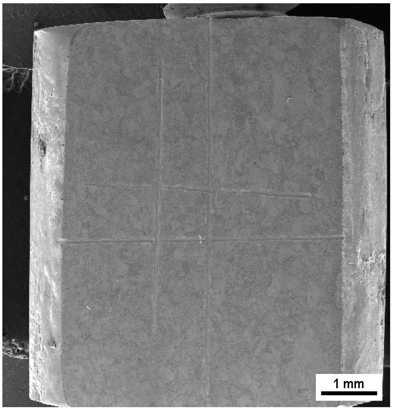
Figure 3.
Continuous extrusion schematic diagram.

Figure 4.
TLJ250 continuous extrusion machine.

Figure 5.
SEM image and EDS pattern of H62 brass. (a) SEM image of H62 brass (b) EDS pattern at position 2 of the bright area (c) EDS pattern at position 1 of the dark area.
Figure 5.
SEM image and EDS pattern of H62 brass. (a) SEM image of H62 brass (b) EDS pattern at position 2 of the bright area (c) EDS pattern at position 1 of the dark area.

Figure 6.
Microstructure before and after upsetting as initial temperature 20 °C, 300 °C, 400 °C and 500 °C: (a) 20 °C, (a’) 20 °C after upsetting, (b) 300 °C, (b’) 300 °C after upsetting, (c) 400 °C, (c’) 400 °C after upsetting, (d) 500 °C, (d’) 500 °C after upsetting (The red rectangles are the observation areas before deformation and the green rectangles are the observation areas after deformation).
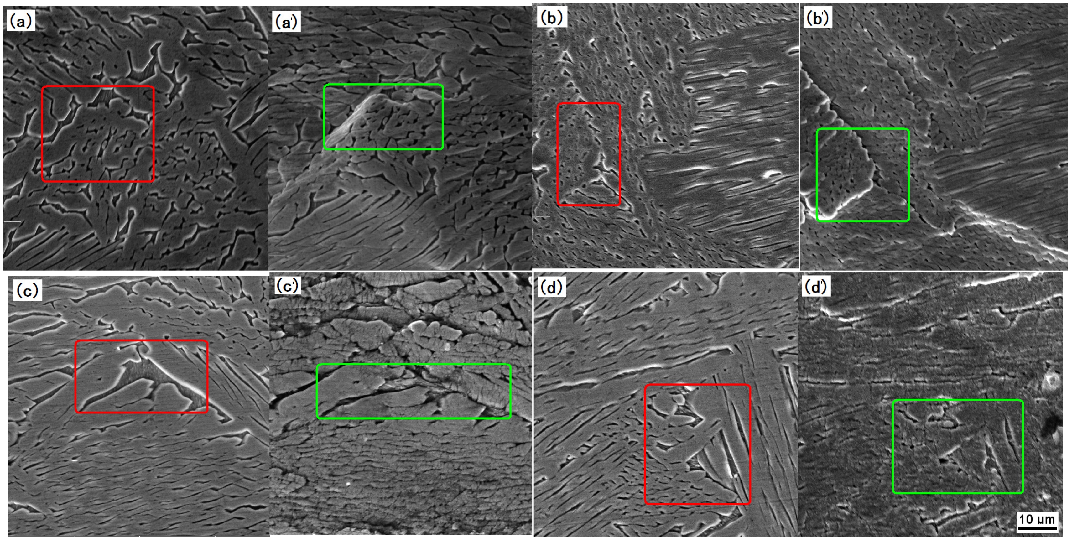
Figure 7.
Effect of different deformation rates on flow under 400 °C and 500 °C: (a) 0.01, (a’) 0.01 after upsetting, 400 °C; (b) 0.1, (b’) 0.1 after upsetting, 400 °C; (c) 0.01, (c’) 0.01 after upsetting, 500 °C; (d) 0.1, (d’) 0.1 after upsetting, 500 °C (The red rectangles are the observation areas before deformation and the green rectangles are the observation areas after deformation).
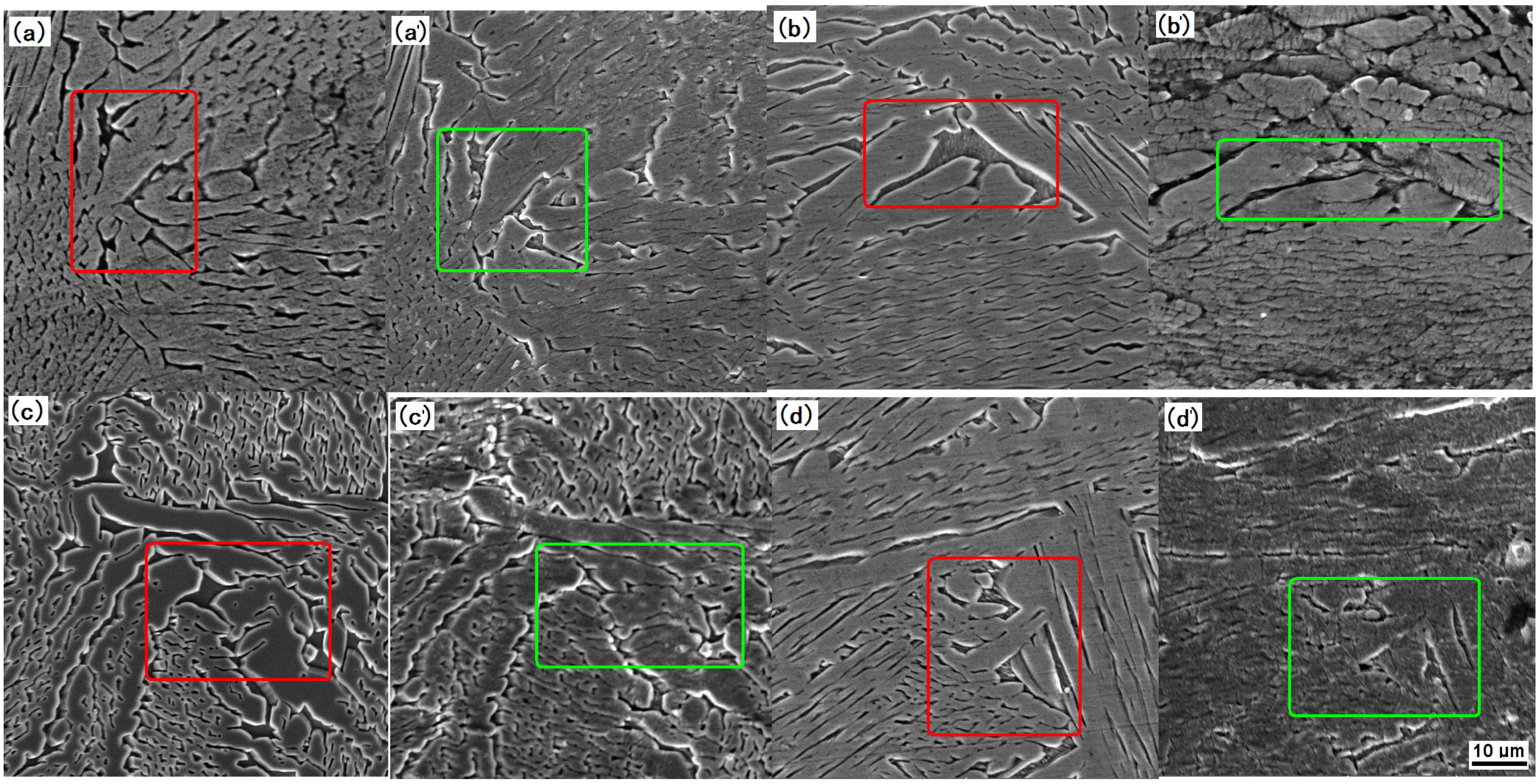
Figure 8.
Effect of deformation strain on flow under 400 °C and 500 °C: (a) 400 °C, strain of 25% before upsetting, (a’) 400 °C, strain 25% after upsetting, (b) 400 °C, strain of 35% before upsetting, (b’) 400 °C, strain of 35% after upsetting, (c) 500 °C, strain of 25% before upsetting, (c’) 500 °C, strain of 25% after upsetting, (d) 500 °C, strain of 35% before upsetting, (d’) 500 °C, strain of 35% after upsetting (The red rectangles are the observation areas before deformation and the green rectangles are the observation areas after deformation).

Figure 9.
Temperature distribution in product along cross-section.
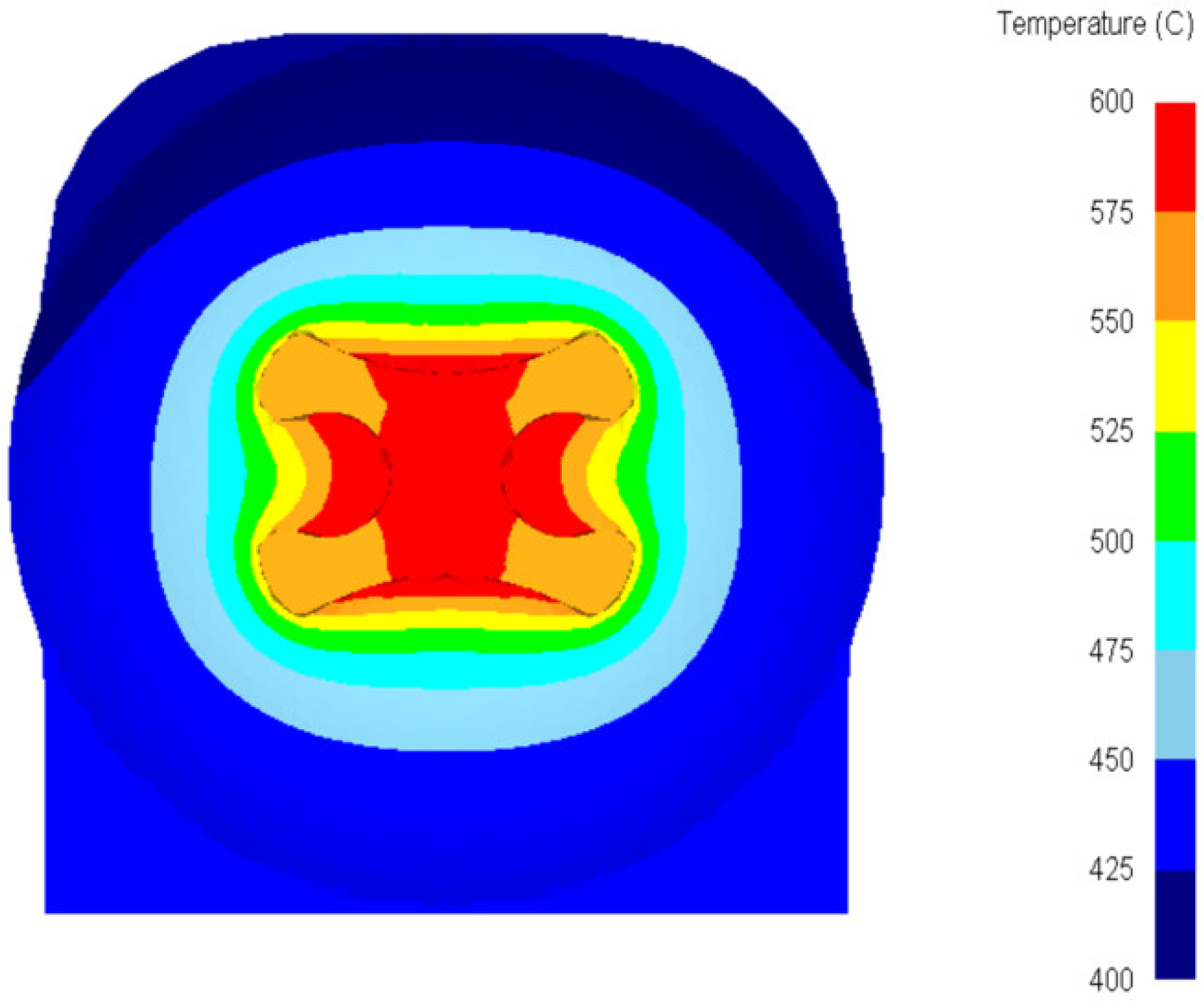
Figure 10.
Point position (a) edge; (b) center.

Figure 11.
Flow velocity SD of different extruding speeds.
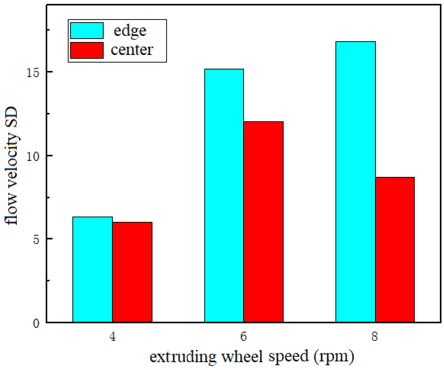
Figure 12.
H-shaped brass wire product (a) section; (b) overall; (c) refined grain in center; (d) refined grain in corner.
Figure 12.
H-shaped brass wire product (a) section; (b) overall; (c) refined grain in center; (d) refined grain in corner.


Table 1.
Experiment program of H62 brass during upsetting.
| Sample No. | 1 | 2 | 3 | 4 | 5 | 6 | 7 | 8 | 9 |
|---|---|---|---|---|---|---|---|---|---|
| Deformation temperature/°C | 20 | 300 | 300 | 400 | 400 | 400 | 500 | 500 | 500 |
| Deformation rate/s−1 | 0.1 | 0.1 | 0.01 | 0.1 | 0.01 | 0.01 | 0.1 | 0.01 | 0.01 |
| Deformation amount/% | 25 | 25 | 25 | 25 | 25 | 35 | 25 | 25 | 35 |
Table 2.
Continuous extrusion numerical simulation parameters.
| Parameters | Values |
|---|---|
| Extruding wheel diameter/mm | 250 |
| Billet length/mm | 100 |
| Extruding wheel speed/rpm | 4/6/8 |
| Extrusion line speed/mm∙s−1 | 52.3/78.5/104.7 |
| Preheat temperature/°C | 500 |
Disclaimer/Publisher’s Note: The statements, opinions and data contained in all publications are solely those of the individual author(s) and contributor(s) and not of MDPI and/or the editor(s). MDPI and/or the editor(s) disclaim responsibility for any injury to people or property resulting from any ideas, methods, instructions or products referred to in the content. |
© 2023 by the authors. Licensee MDPI, Basel, Switzerland. This article is an open access article distributed under the terms and conditions of the Creative Commons Attribution (CC BY) license (https://creativecommons.org/licenses/by/4.0/).
Share and Cite
MDPI and ACS Style
Li, B.; Fu, Q.; Yu, R.; Lin, Z.; Wang, J.; Wang, X.; Guan, R.; Li, J. Two-Phase Flow Coordination Characteristics of H62 Brass Alloy Prepared by Up-Drawing Continuous Casting. Metals 2023, 13, 599. https://doi.org/10.3390/met13030599
AMA Style
Li B, Fu Q, Yu R, Lin Z, Wang J, Wang X, Guan R, Li J. Two-Phase Flow Coordination Characteristics of H62 Brass Alloy Prepared by Up-Drawing Continuous Casting. Metals. 2023; 13(3):599. https://doi.org/10.3390/met13030599
Chicago/Turabian StyleLi, Bing, Qianqian Fu, Rongzhou Yu, Zikai Lin, Jun Wang, Xue Wang, Renguo Guan, and Jiehua Li. 2023. "Two-Phase Flow Coordination Characteristics of H62 Brass Alloy Prepared by Up-Drawing Continuous Casting" Metals 13, no. 3: 599. https://doi.org/10.3390/met13030599
Note that from the first issue of 2016, this journal uses article numbers instead of page numbers. See further details here.