

Evaluation of Mechanical Properties of Different Casing Drilling Steels

1
School of Materials Science and Engineering, Xi’an University of Technology, Xi’an 710048, China
2
School of Materials Science and Engineering, Xi’an Shiyou University, Xi’an 710065, China
*
Author to whom correspondence should be addressed.
Metals 2023, 13(2), 427; https://doi.org/10.3390/met13020427
Submission received: 5 December 2022
/
Revised: 5 February 2023
/
Accepted: 10 February 2023
/
Published: 19 February 2023
Abstract
:An investigation into the mechanical properties of K55, N80, and P110 steels commonly used for casing drilling was carried out together with microstructural and fractographic analysis. The results show that P110 steel consisted of almost fully tempered martensite and exhibited a synergy combination of static tensile, dynamic impact, and fatigue crack propagation properties among the three steels, possessing a higher fatigue limit and deeper crack tolerance before failure occurred. The K55 steel consisted of the pearlite and network structure of ferrite and possessed a high strain hardening exponent and low impact property, which led to the more suitable application under incidental large overload and temperature change, but it was unsuitable under the condition of higher impact force. The properties of N80 steel were moderate, and its fatigue property was higher than that of K55 and lower than that of P110; its incidental overload resistance was also higher than that of P110. The casing drilling steel can be selected according to the environment.
1. Introduction
Drilling with casing is an innovative technology serving as a solution to mitigate wellbore stability issues and service costs [1,2,3,4]. With the development of the novel drilling technology (casing drilling), casings were affected by several extreme operating conditions [5], such as extremely high pressures or mechanical loading. Traditionally, in the period of casing drilling, transmitting of torque and power could be achieved through casing string [6]. In actual casing drilling, because of the inappropriate torque or degeneration of the casing properties, the casings are commonly damaged, especially caused through parting or splitting [7]. Thus, developing the service characteristics of casing has attracted increasing concern.
Based on present application status, J55, K55, L80, N80, C95, and P110 were chosen for drilling and casing services due to their higher mechanical properties preferentially. It should be noted that tools derived from casing drilling steels worked in a complex underground mining environment. Tremendous cyclic loading combined with stress and strain limited a multitude of steels for fabricating casing drilling materials. In this case, a single property of the steels chosen as candidates to meet the requirement of the study was insufficient. From the related research [8,9], few researchers provided the combination properties of the individual type of casing drilling steel. Most investigations performed were concerned with a single factor, such as working temperature, tensile strength, and impact property. Gaute Gruben et al. [8] studied the properties of steels such as K55 and P110. However, in the mentioned work, few experimental data about microstructure and phase distribution can be seen when only proper working temperatures were present. Obviously, this was insufficient for developing casing steels with higher mechanical properties by temperature results. Bert Dillingh et al. offered a relatively comprehensive research paper on the dependence between temperature and tensile properties of K55 and L80 steels [9]. From their experimental data, the investigation covered the tensile fracture position and the macroscopical morphology of the fracture surface, which also did not cover the important impact properties and fatigue properties during drilling. Due to the lack of microstructural details and impact fracture information, fracture mechanism and working stability were still unclear. Similarly, Lei and his team [10] investigated on Impact Test and Error Analysis of N80 Waterproof Casing. Regrettably, no images of fracture surfaces were involved in this work. At the same time, for the choice of casing drilling steel by satisfying certain properties, other properties were commonly ignored, which led to more accidents. Thus, it is indispensable to investigate the overall performance of the specific potential casing drilling steels. By analyzing the work condition of casing drilling steels, it was reasonable to believe that the material failure mode of casing drilling steels was governed by cyclic stress and strain. And the basis for developing casing drilling steel can be attributed to microstructure and fracture mechanisms combined with tensile and impact properties.
Therefore, to comprehensively investigate the performance, tensile strength, impact toughness, and fatigue crack propagation are explored for the casing steels K55, N80, and P110. The quasi-static and dynamic casing performance and fatigue crack growth behavior are evaluated individually, and the detailed fractographies are observed and analyzed, with a particular focus on the mode of action of microstructure on the mechanical properties. Based on the deficiency of existing research, more detailed studies should be carried out in future work, such as grain boundary engineering, in-situ mechanical tests, texture distribution, and the effects of precipitation on fracture mode.
2. Materials and Methods
The materials concerned in this investigation were supplied in the form of coupling by Tubular Goods Research Center of CNPC with a thickness and diameter of 11.43 mm and 244.48 mm, respectively. The raw materials that were used for producing casing drilling steels are presented in Table 1 (wt.%). The basic composition followed the requirement of the API Specification 5CT—8th Edition. As illustrated in Table 1, few differences can be found in the contents of C, Mn, S, and P in three casing drilling steels.
The K55 steel was obtained from a thermal treatment with an austenitizing temperature of 1000 °C for 30 min and cooled in air. To N80 steel, the mentioned thermal treatment of austenitizing temperature was reduced to 810 °C for 30 min. Then it was cooled by air. A subsequent tempering process was carried out at a temperature of 600 °C for 2 h, and final air-cooling was performed when previous heat treatments were completed. P110 steel held a 90 °C lower austenitizing temperature (910 °C for 30 min) than that of K55 steel. After the air-cooling treatment, the subsequent tempering process was achieved at 550 °C for 2 h. Finally, the tempered P110 steel was cooled by air.
The specimens for optical microscope observations were chemically etched in a solution of 4% HNO3 + ethanol. The volume fractions of different phases in the microstructure of casing drilling steels were measured by using an optical microscope (Carl Zeiss AG, Oberkochen, GER) and MEF4M Micro-image Analysis & Process image analyzer software(Leica Microsystems, Wentzler, GER).
Macrohardness values were obtained by an HB-3000C type Brinell hardness tester (Laizhou Huayin Testing Instrument Co., Ltd, Shandong, CN)with a 2.5 mm diameter steel ball to apply a load of 1837.5N for 10 s. The value of the hardness was obtained by the average of 5 measurements. Micro-hardness measurements were conducted on distinct regions in the samples using a hardness tester (HVS-1000A) (Laizhou Huayin Testing Instrument Co., Ltd, Shandong, CN) with a constant load of 0.49N, as observed via an optical microscope.
Figure 1 presents the specific piece positions that were used for further tests. The room temperature tensile properties for each specimen were measured using 5 samples with a gauge length of 35.6 mm and a diameter of 8.9 mm. The specimens were tested on a CMT5105 universal testing machine (Tianjin Meitesi Testing Machine Factory, Tianjin CN) at a strain rate of 1 × 10⁻³ s−1.
Charpy V-notch (CVN) specimens taken from the same position as the tensile ones were used for the impact with a size of 7.5 mm × 10 mm × 55 mm, as depicted in Figure 1. The V-type notch was machined with a depth of 2 mm and a root radius of 0.25 mm. All impact specimens were immersed in ethanol at 0 °C for 5 min and then tested in an 84-type standard Charpy impact tester.
Fatigue tests were conducted on the compact tension (CT) specimens with a 4.8 mm thickness and 30 mm width according to the ASTM E647 standard. A pre-existing crack was introduced at a distance greater than 2 mm from the notch root. Testing of the fatigue crack propagation (FCP) was performed on a DPL-100 servohydraulic fatigue (Xi’an Lichuang Material Testing Technology Co., LTD, Shaanxi, CN) testing machine at room temperature (25 °C). The testing was conducted using a sinusoidal waveform at a constant amplitude loading and a frequency f = 10 Hz. By controlling the crack length, we ensured that the crack extension length under each level of loading exceeded the plastic zone of the fatigue crack tip before changing to the next level of loading, with a maximum load of 1.4 kN, and a stress ratio, R (R = σmin/σmax), of 0.1. The length of a crack was monitored by a microcomputer-aided crack propagation measurement system. The potential function was calculated by boundary element methods [11]. The fatigue tests were carried out until specimen failure occurred.
The fractographies of CVN and tensile specimens were analyzed using a TESCAN VEGAIIXMH scanning electron microscope ( TESCAN performance in nanospace, Brno, CZ).
3. Results
3.1. Microstructure Characterization
The microstructures of K55, N80, and P110 steels acquired from the optical microscope were shown in Figure 2a–c, respectively. Clearly, features in the microstructures of the three types of steels were remarkably different. The microstructure of the P110 specimen mainly consisted of tempered martensite (TM), and that of N80 steel also included a small amount of polygonal ferrite (F) and upper bainite (Bu) besides TM (FBM). The microstructure of K55 steel consisted of a coarse structure of ferrite (F) (dark area) and pearlite (P) (light area), and the coarse pearlitic grains were surrounded by fine ferrite daisy chained around prior austenitic grain boundaries.
Image analysis of the microstructures indicated that the average contents of bainite, ferrite, and martensite were 8%, 17%, and 75%, respectively, for the N80 steel. While the average contents of bainite and martensite were 2% and 98% for the P110 steel, and that of ferrite and pearlite were 14% and 86% for the K55 steel.
3.2. Hardness and Tensile Behavior
The average values of the Brinell hardness of each casing drilling steel are presented in Table 2. As can be seen from Table 2, the P110 and K55 steels possessed the highest and lowest Brinell hardness value among the three types of steels, respectively, and the results of Vickers microhardness measurements are consistent with the Brinell macrohardness measurements.
The stress–strain relationships of three types of casing drilling steels are presented in Figure 3, and the tensile properties are listed in Table 3. It can be seen from Figure 3 and Table 3 that the tensile properties of the three types of steels possessed remarkable differences. Both the yield and tensile strengths of P110 steel were noticeably higher than those of the other two steels (N80 and K55), whereas K55 steel had the lowest yield and tensile strength. This is attributed to the fact that the microstructure of P110 steel consisted of almost full TM, whereas that of K55 steel mainly included pearlite and ferrite, as shown in Figure 2a, and stress concentrations were prone to appear at the ferrite/cementite interfaces of pearlite along the plane of maximum resolved shear stress, which facilitates crack initiation. This type of crack initiation process has been studied extensively in the literature in the case of tensile specimens [12]. Moreover, some recent research results were chosen to make a simple comparison, as shown in Table 3. From the comparison, it was clear that most related work was concerned with a single mechanical property. Additionally, all the research did not cover the impact property, which was insufficient to provide objective evaluation results. By comparing common data in the research, yield strength, and tensile strength of K55 and N80, it was observed that they were relatively stable to others’ works, and they were much lower than that of P110. Besides, the mechanical features of the P110 sample in this work present a distinct higher performance than that of P110s from [13]. This proved that just microstructural adjustment could enhance the mechanical characteristic of identical steel material.
The low yield strength of N80 steel compared to P110 steel is due to the fact that some ferrites and upper bainite were present in the microstructure, which can remarkably decrease the yield strength. However, the prior austenite grain size of N80 steel is 20 μm, which was remarkably smaller than that of the P110 steel at 50 μm. This was due to the fact that the resistance to dislocation movement was provided by the fine-scale tempered carbide distribution, so dislocation tangled around the particles, and no simple “pile-up” arrays traversing the length of grain were created [16].
Investigations into a great amount of steel materials indicated that the material fatigue limit was proportional to the tensile strength, particularly in the tensile strength range corresponding to the three types of casing drilling steels, and almost all of the fatigue ratios (ratio of fatigue limit to tensile strength) of all the steels were higher than 0.5 [17]. Thus, 0.5 can be selected as the fatigue ratio of casing drilling steels K55, N80, and P110:
where Sf is the fatigue limit in MPa and σb is the ultimate tensile strength in MPa.
Sf = 0.5σb
It can also be seen from Figure 3 that the uniform elongations of three types of casing drilling exhibited a decreasing trend with increasing yield strength. This result is in agreement with the existing literature, which indicates that uniform elongation (UE) is related to the yield stress (σ0.2) by the following relation [18,19]:
UE = 23 − 31.7 (log σ0.2 − 2.4)
The elongations of the K55, N80, and P110 steels are shown in Figure 4a, and it can be found that the uniform elongations of both N80 and P110 steels were obviously lower compared to that of K55 steel, which indicates that K55 steel may possess a superior strain capacity. This can be attributed to the fact that the yielding in the soft ferrite phase of K55 steel occurred at first, then the load transferred to the hard pearlite phase [20,21].
N80 steel has higher uniform elongation than P110. This can be attributed to the fact that the ferrite content was 17%, and the martensite content was 75% in the N80 steel, whereas the martensite content was 98% in the P110 steel. At the same time, Khakian also found that in bainite–ferrite dual-phase 4340 steel, the elongation increased with the increase in ferrite volume fraction by up to 34% [21]. So, it was expected that N80 steel would possess higher elongation compared to P110 steel.
It can also be seen from Figure 4 that the total elongations of the three types of steels exhibited the same trend as the uniform elongation, but the ratio of the yield strength to ultimate tensile strength (YS/UTS) exhibited an opposite trend, although there was no significant difference among the chemical compositions of the three steels. The YS/UTS of N80 steel was 0.76, which was noticeably lower in comparison with that of P110, which is 0.9. This was due to the fact that traces of ferrite and bainite presented in the N80 microstructure as well as the dominantly tempered martensite, while P110 steel possessed almost fully tempered martensite. It has been generally known to have high deformability in the dual-phase microstructure [21].
K55 possessed the lowest YS/UTS among the three steels, which was attributed to its pearlite microstructure. This is consistent with other studies [18,22], and the K55 steel showed a yield strength of 403 MPa, uniform elongation of 13.01 %, and yield ratio of 0.57, which indicated the good deformability of K55 steel. A lower YS/UTS value indicates enhanced resistance to localized yielding. This was consistent with both the tensile and impact fracture feature among the three steels; additionally, the K55 tensile fracture exhibited the smallest reduction in area, and little local plastic deformation occurred on the K55 impact fracture surface.
In general, the higher uniform elongation and strain hardening exponent of materials can avoid localized plastic deformation and ensure the security of the casing service, particularly under the condition of an incidental larger overload. When uniform deformation and strain hardening occur in the materials, it can lead to plastic deformation transferring to the non-plastic deformation zone from the plastic deformation zone and ensuring the security of the casing service. Based on this viewpoint, it can be forecasted that K55 steel possesses higher accidental overload resistance compared to both P110 and N80 steels, although both the tensile and fatigue strengths are low.
The fractographies of the tensile specimens, as shown in Figure 5, show that the microstructures of the fracture surfaces included smaller dimples for the N80 and P110 specimens. This was due to the fact that their microstructures mainly consisted of TM, the dimples originating from the carbides of the tempering martensite. The fractographic investigations indicate that a fracture mechanism of microvoid growth and coalescence occurred in the TM fracture (Figure 5b,c). On the other hand, in the K55 tensile specimens, larger sulfide inclusions were present in the matrix, which resulted in the appearance of some larger caves on the tensile fracture surface of the K55, as shown in Figure 5a.
3.3. Impact Behavior
It can also be seen from Table 3 that the impact toughness values of both N80 and P110 steels were almost the same, but both of them were significantly higher than K55 steel. Both the P110 and N80 specimens absorbed up to about five times the impact energy in comparison with the K55 specimens.
This is attributed to the fact that both P110 and N80 specimens mainly consisted of tempered martensite, whereas the microstructure of the K55 specimen mainly consisted of pearlite and ferrite. The tempered martensite structure commonly caused the specimen to fracture by void initiation and aggregation, as shown in Figure 6b,c, which commonly consumed more impact energy than cleavage fracture, whereas the pearlite and ferrite microstructure commonly caused the specimen to fracture by cleavage mode in impact testing, as shown in Figure 6a. Though K55 steel possessed higher uniform elongation, its tensile fracture was characterized by dimples. This can be attributed to the fact that the strain rate was higher during the impact testing, and the time was too short for the initiation and growth of dimples and cavities with strain around the inclusions or second-phase particles under the impact load [23]. At the same time, the presence of a large number of cleavage facets on the fracture surface of K55 steel could also be found, as shown in Figure 6a, which were greater than the size of the largest pearlite colony, and there were occasionally small areas of ductile tearing. It could be explained as the easiness of cracks traversing through several pearlite colonies to form a single cleavage facet without necessarily changing direction at pearlite colony boundaries. This is attributed to the fact that less misorientation occurred between most of the cleavage surface in the adjacent pearlite colony.
Based on the above testing results, the material fracture toughness values can be obtained, and a safety assessment can be performed. Ule et al. obtained the following equation through a large amount of testing [18]:
where KIC is the fracture roughness in MPa√m, σ0.2 yield is the strength in MPa, and CVN is the impact energy value in J.
Thereby, the fracture toughness values of K55, N80, and P110 steels can be determined based on Equation (3), which were 47.9 MPa√m, 77.8 MPa√m, and 96.8 MPa, respectively.
3.4. Fatigue Crack Growth Behaviors
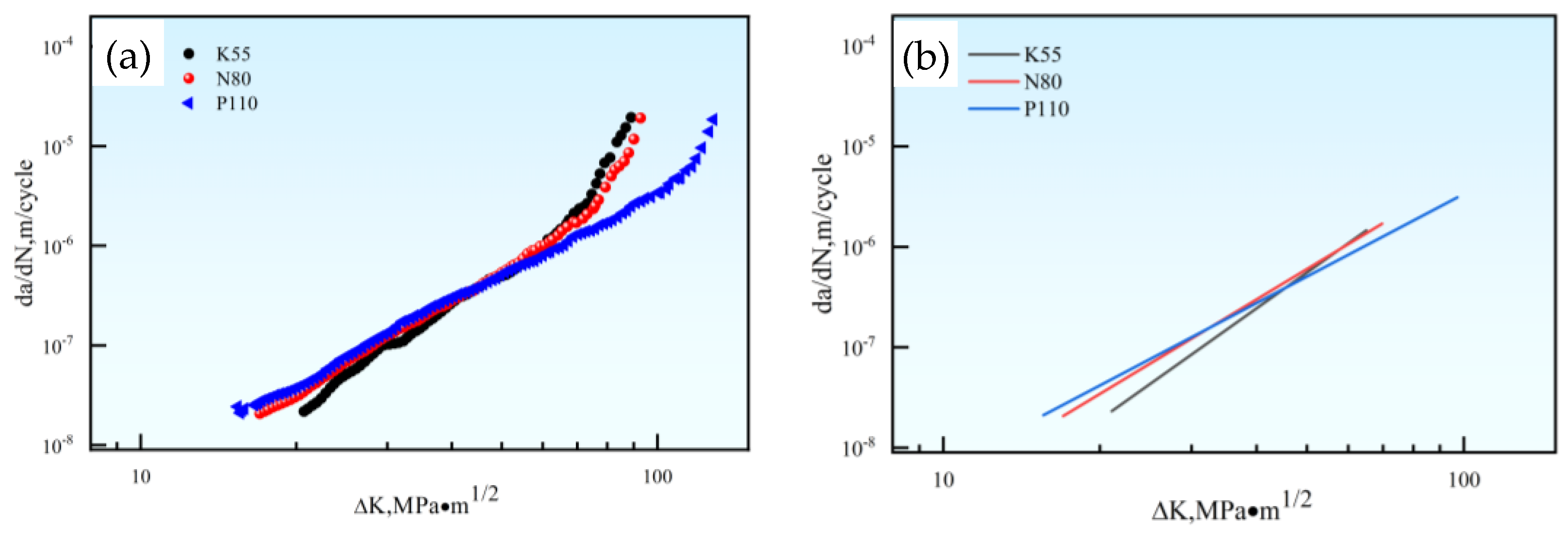
The fatigue crack growth behaviors for the three types of casing drilling steels are shown in Figure 7a. The Paris constants (C and m) were obtained through a least squares fitting procedure based on Paris Formula (4) [24]:
where (da/dN) are the fatigue crack growth rates in m/cycle, ∆K is the stress intensity factor range in MPa√m, and m and C are material constants.
The m and C values of each casing drilling steel are given in Table 4. It can be seen from Table 4 that the m and C values were consistent with the literature [25,26].
It could also be observed from Figure 7 and Table 4 that K55 steel possessed a high Paris constant m, and the unstable crack propagation occurred at the low ∆K; while P110 steel possessed a low Paris constant m, and the unstable crack propagation occurred at the high ∆K; and N80 possessed moderate Paris constant m, and the unstable fracture occurred at the moderate ∆K. Thus, it can be expected that the growing crack length is more easily monitored and measured for the P110 steel used as drilling casing.
The fatigue crack growth life formula can be obtained based on Equation (5), which is valid only if ai and af are (i) long cracks and (ii) the relevant DK values fall in the Paris’ regime, as follows:
where N is the number of fatigue cycles, a is the crack length in m, αi is the initial crack length in m, αc is the crack length of the component in m, ∆K is the stress intensity factor range in MPa√m, and m and C are material constants.
4. Conclusions
(1) P110 steel consisted of almost full-tempered martensite and exhibited a synergistic combination of static tensile, dynamic impact, and fatigue crack propagation properties among the three steels. It possessed not only a high fatigue limit but also deep crack tolerances before the occurrence of failure, which resulted in fewer materials, lower cost, and easier monitoring and measuring of the growing crack length when used as drilling casing. However, the shortage of the P110 steel was a significant low strain hardening exponent, which led to the unsuitable application of P110 steel under the condition of great temperature changes and incidental large overload.
(2) K55 steel consisted of the pearlite and network structure ferrite and possessed a high strain hardening exponent, which led to a more suitable application under incidental large overload and temperature change, particularly in steam-injection wells. However, K55 steel possessed significantly low impact energy and strength; thus, it was unsuitable under the condition of higher impact force.
(3) The combination property of N80 steel was moderate among three casing steels, and its microstructure consisted of tempered martensite, with a small amount of ferrite and upper bainite. The fatigue property of N80 steel was lower than that of P110 and higher than that of K55, and its impact energy value was almost equal to that of P110. The incidental overload resistance of N80 steel was lower than that of K55 and higher than that of P110. It can be expected that N80 steel can be selected and applied to some well environments.
Author Contributions
Methodology, X.H. and M.Z.; Validation, X.H. and M.Z.; Data curation, X.H. and L.L.; Writing—original draft preparation, X.H.; Writing—review and editing, X.H., T.X., L.L., and Y.L.; Project administration, M.Z. Resources, T.X. All authors have read and agreed to the published version of the manuscript.
Funding
This research was funded by National Natural Science Foundation of China, grant number No.51974243 and Xi’an Municipal Science and Technology Planning Project, grant number No.21XJZZ0057.
Data Availability Statement
Not applicable.
Conflicts of Interest
The authors declare no conflict of interest.
References
- Patel, D.; Thakar, V. A review on casing while drilling technology for oil and gas production with well control model and economical analysis. Petroleum 2019, 5, 1–12. [Google Scholar] [CrossRef]
- Osman, O.; Merah, N. Casing Wear and Wear Factors: New Experimental Study and Analysis. Materials 2022, 15, 6544. [Google Scholar] [CrossRef] [PubMed]
- Cirimello, P.; Otegui, J. Failure and integrity analysis of casings used for oil well drilling. Eng. Fail Anal. 2017, 75, 1–14. [Google Scholar] [CrossRef]
- Wang, G.; Li, W. Technological Process of the Composite Casing Drilling Technology in Deep-Water Riserless well Construction. Chem. Tech. Fuels Oil 2022, 58, 95–103. [Google Scholar] [CrossRef]
- Bailey, G.; Strickler, R.; Hannahs, D.; Kamruzzaman, S. Evaluation of a Casing Drilling Connection Subjected to Fatigue and Combined Load Testing. In Proceedings of the Offshore Technology Conference, Houston, TX, USA, 1–4 May 2006. [Google Scholar]
- Zhao, Z.; Gao, D.L. Casing strength degradation due to torsion residual stress in casing drilling. J. Nat. Gas Sci. Eng. 2009, 1, 154–157. [Google Scholar]
- Samit, G.; Sean, E. API Specification 5CT N-80 Grade Casing May Burst or Part Unexpectedly if Supplementary Metallurgical Requirements are not Specified. In Proceedings of the SPE/IADC Drilling Conference, Amsterdam, The Netherlands, 23–25 February 2005. [Google Scholar]
- Gruben, G.; Dillingh, B. Thermo-mechanical tensile testing of geothermal casing materials. Geothermics 2021, 89, 101944. [Google Scholar] [CrossRef]
- Dillingh, B.; Thorbjornsson, G.S.K.I. Tensile Testing of Casing Material at Elevated Temperatures up to 550 °C. In Proceedings of the World Geothermal Congress, Reykjavik, Iceland, 26 April–2 May 2020. [Google Scholar]
- Lei, S.; Wei, M. Impact Test and Error Analysis of N80 Waterproof Casing. AMR 2013, 816, 317–321. [Google Scholar]
- Lu, M.; Zheng, X. A new microcomputer-aided system for measuring fatigue propagation threshold and selection testing parameters. Eng. Fract. Mech. 1993, 45, 889–896. [Google Scholar] [CrossRef]
- Fernandez-Vicente, A.; Cars, M.; Penalba, F.; Taleff, E.; Ruano, O. Toughness dependence on the microstructural parameters for an ultrahigh carbon steel (1.3 wt.% C). Mater. Sci. Eng. A 2002, 335, 175–185. [Google Scholar] [CrossRef]
- Zvirko, O.; Tsyrulnyk, O. Evaluation of Corrosion, Mechanical Properties and Hydrogen Embrittlement of Casing Pipe Steels with Different Microstructure. Materials 2021, 14, 24. [Google Scholar] [CrossRef] [PubMed]
- Li, M.F.; Cao, L.H. An Experimental Study on Mechanical properties of P110S under Dynamic Loads. IOP Conf. Ser. Mater. Sci. Eng. 2018, 392, 62020. [Google Scholar] [CrossRef]
- Zhang, H.; Luo, Q. Fracture Failure Analysis of N80 Q Marine Casing. In Applied Mechanics and Materials; Trans Tech Publications Ltd.: Bach, Switzerland, 2013; Volume 318, pp. 331–335. [Google Scholar]
- Balart, M.; Knot, J. Low temperatFure fracture properties of DIN 22NiMoCr37 steel in fine-grained bainite and coarse-grained tempered embrittled martensite microstructures. Eng. Fract. Mech. 2008, 75, 248–251. [Google Scholar] [CrossRef]
- Fuchs, H.O. Metal Fatigue in Engineering; John Wiley & Sons: Hoboken, NJ, USA, 1980; pp. 70–82. [Google Scholar]
- Tuma, J.V. Low-temperature tensile properties, notch and fracture toughness of steels for use in nuclear power plant. Nucl. Eng. Des. 2002, 211, 105–119. [Google Scholar] [CrossRef]
- Sakuma, Y.; Matlock, D.K.; Krauss, G. Mechanical behavior of an intercritically annealed and isothermally transformed low C alloy steel with ferrite-bainite-austenite microstructures. J. Heat Treat. 1990, 8, 109–120. [Google Scholar] [CrossRef]
- Hwang, B.; Lee, C. Influence of thermomechanical processing and heat treatments on tensile and Charpy impact properties of B and Cu bearing high-strength low-alloy steels. Mater. Sci. Eng. A 2010, 527, 4341–4346. [Google Scholar] [CrossRef]
- Hwang, B.; Lee, C.; Lee, S. Microstructure and mechanical properties of ultra-high strength steel plates with deformability. Mater. Sci. Forum. 2010, 638–642, 3266–3271. [Google Scholar] [CrossRef]
- Saeidi, N.; Ekrami, A. Impact properties of tempered bainite-ferrite dual phase steels. Mater. Sci. Eng. 2010, 527, 5575–5581. [Google Scholar] [CrossRef]
- Maweja, K.; Mater, W.S. The design of advanced performance high strength low-carbon martensitic armour steels Part 1. Mechanical property considerations. Mater. Sci. Eng. A 2008, 485, 140–153. [Google Scholar] [CrossRef]
- Paris, P.; Erdogan, F. A critical analysis of crack propagation laws. Trans. ASME Ser. D 1963, 85, 528–535. [Google Scholar] [CrossRef]
- Sankaran, S.; Sarma, V.; Padmanabhan, K.A. High cycle fatigue behaviour of a multiphase microalloyed medium carbon steel: A comparison between ferrite–pearlite and tempered martensite microstructures. Mater. Sci. Eng. A 2003, 362, 249–256. [Google Scholar] [CrossRef]
- Suresh, S. Fatigue of Materials; Cambridge University Press: Cambridge, UK, 1991. [Google Scholar]
Figure 1.
Schematic of specimen preparation from the casing coupling.
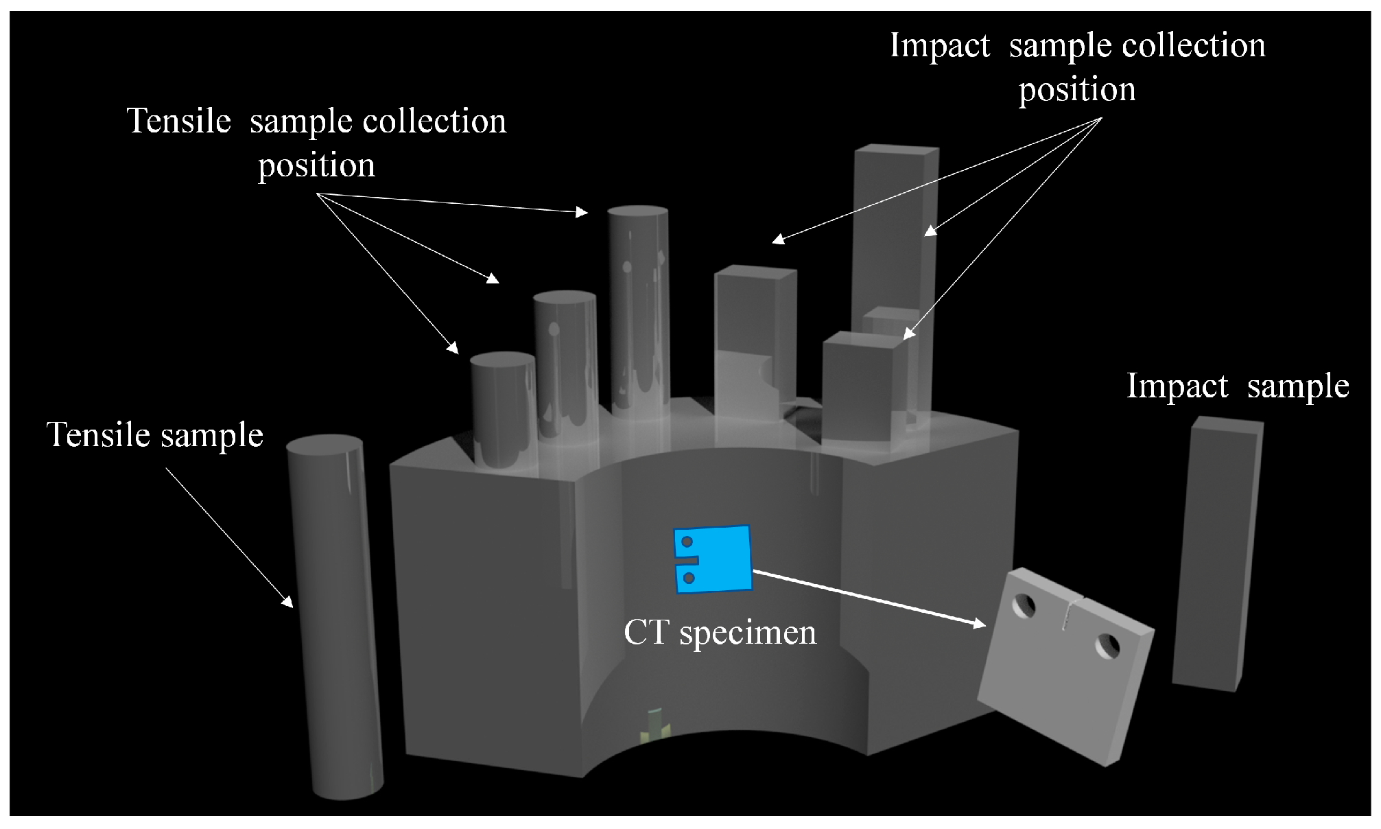
Figure 2.
Optical micrographs of casing drilling steels. (a) Micrograph of K55 steel; (b) micrograph of N80 steel; (c) micrograph of P110 steel.
Figure 2.
Optical micrographs of casing drilling steels. (a) Micrograph of K55 steel; (b) micrograph of N80 steel; (c) micrograph of P110 steel.
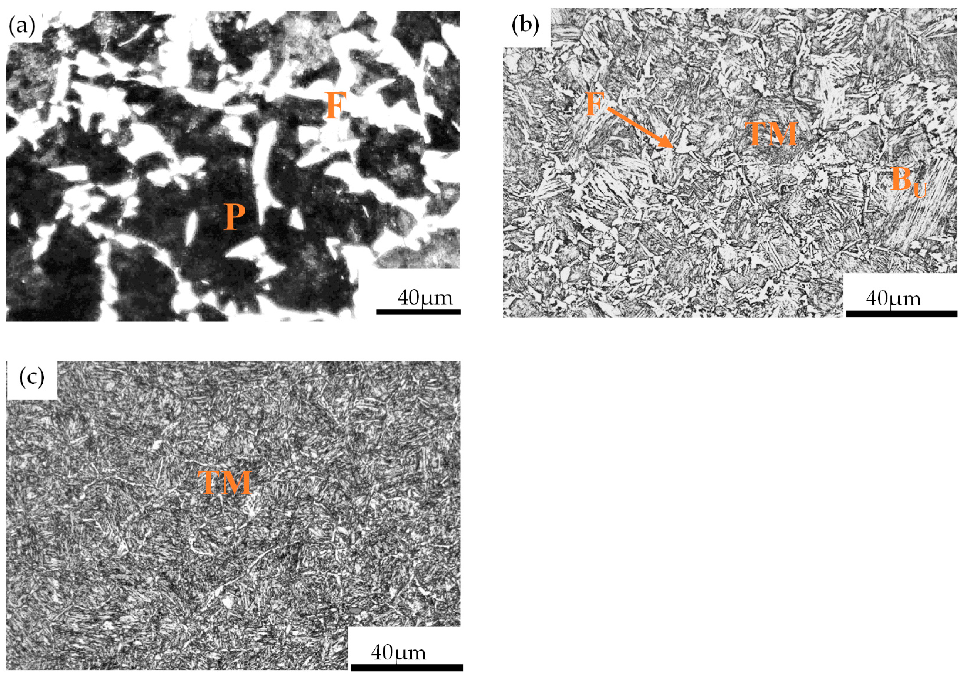
Figure 3.
Tensile curves of different casing drilling steel.
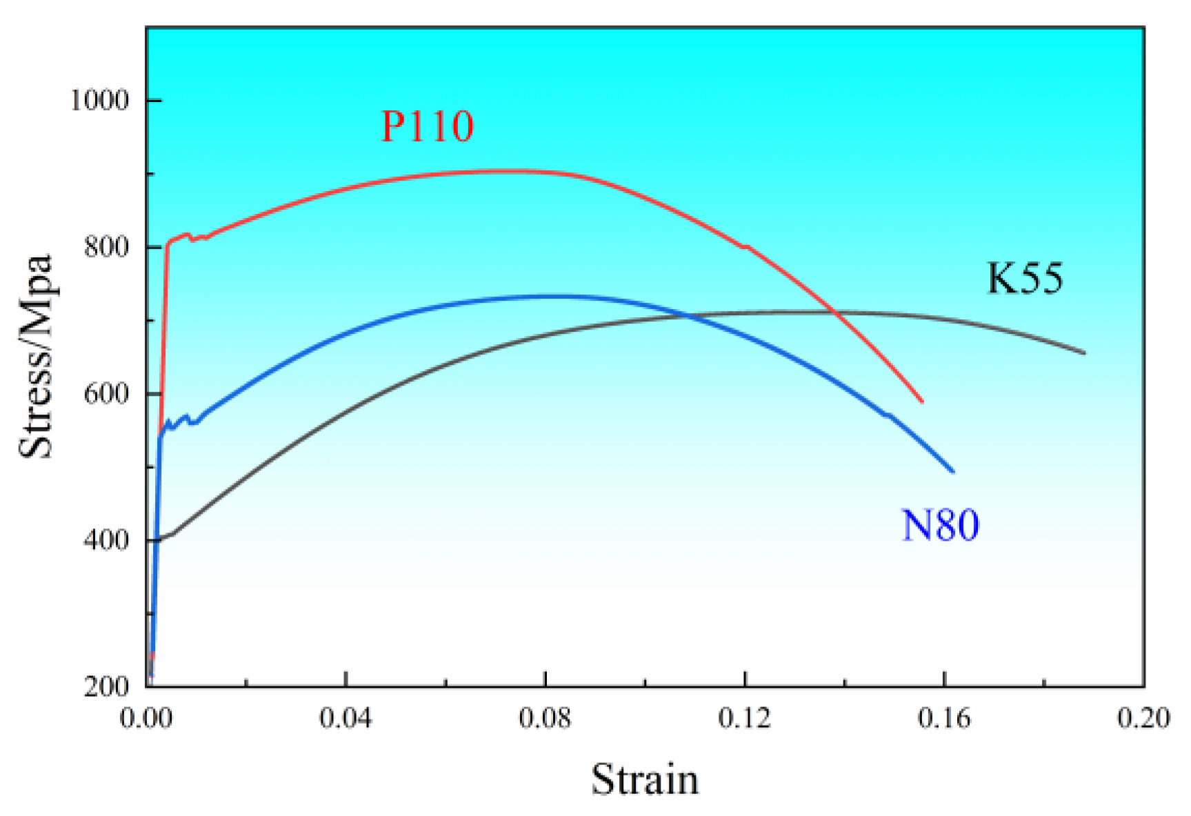
Figure 4.
Comparison between the elongation (a) and YS/UTS (b) of three types of casing drilling steels.
Figure 4.
Comparison between the elongation (a) and YS/UTS (b) of three types of casing drilling steels.
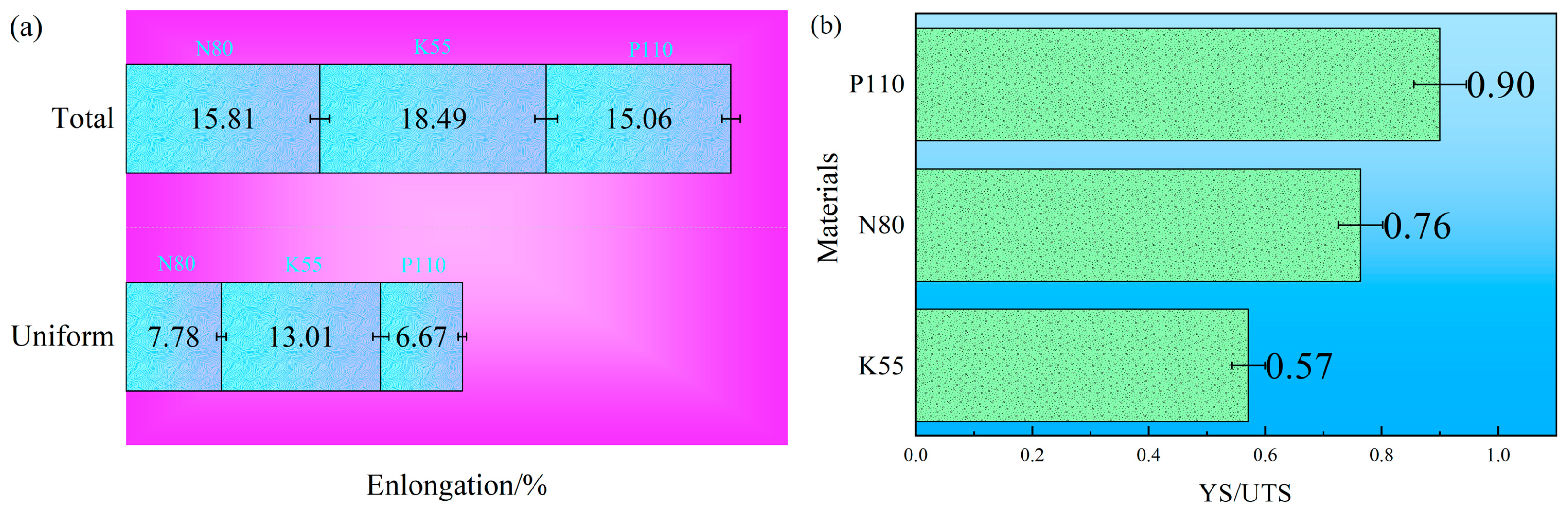
Figure 5.
SEM micrographs of tensile fracture surfaces of different casing drilling steels; (a) dimples and caves on the fracture surface of K55 specimen; (b) dimples on the fracture surface of N80 specimen; (c) dimples on the fracture surface of P110 specimen.
Figure 5.
SEM micrographs of tensile fracture surfaces of different casing drilling steels; (a) dimples and caves on the fracture surface of K55 specimen; (b) dimples on the fracture surface of N80 specimen; (c) dimples on the fracture surface of P110 specimen.
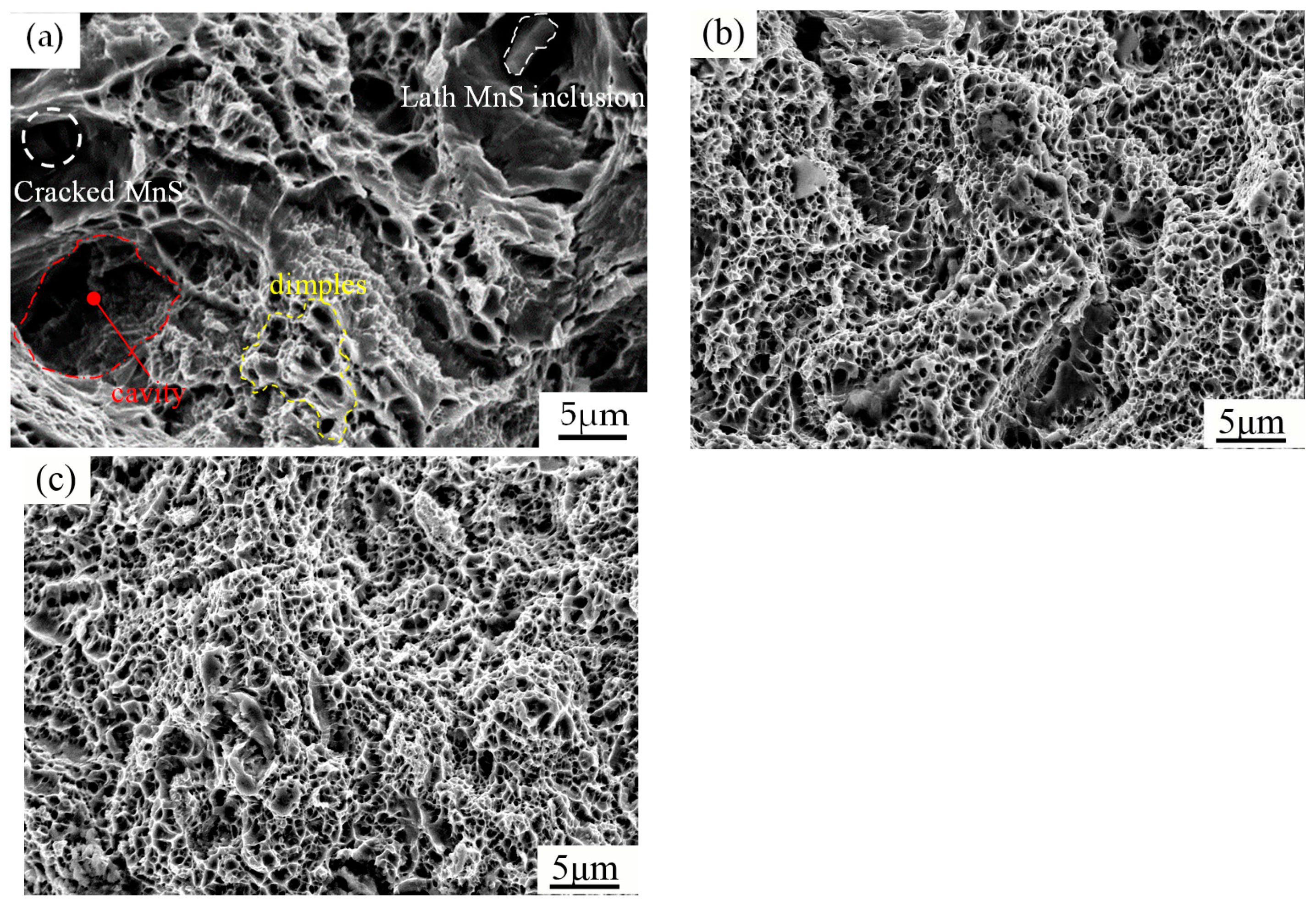
Figure 6.
SEM micrographs of impact fracture surfaces of different casing drilling steels (a) Transgranular cleavage facets on the fracture surface of K55 specimen; (b) a ductile fracture mode on the fracture surface of N80 specimen; (c) a ductile fracture mode on the fracture surface of P110 specimen.
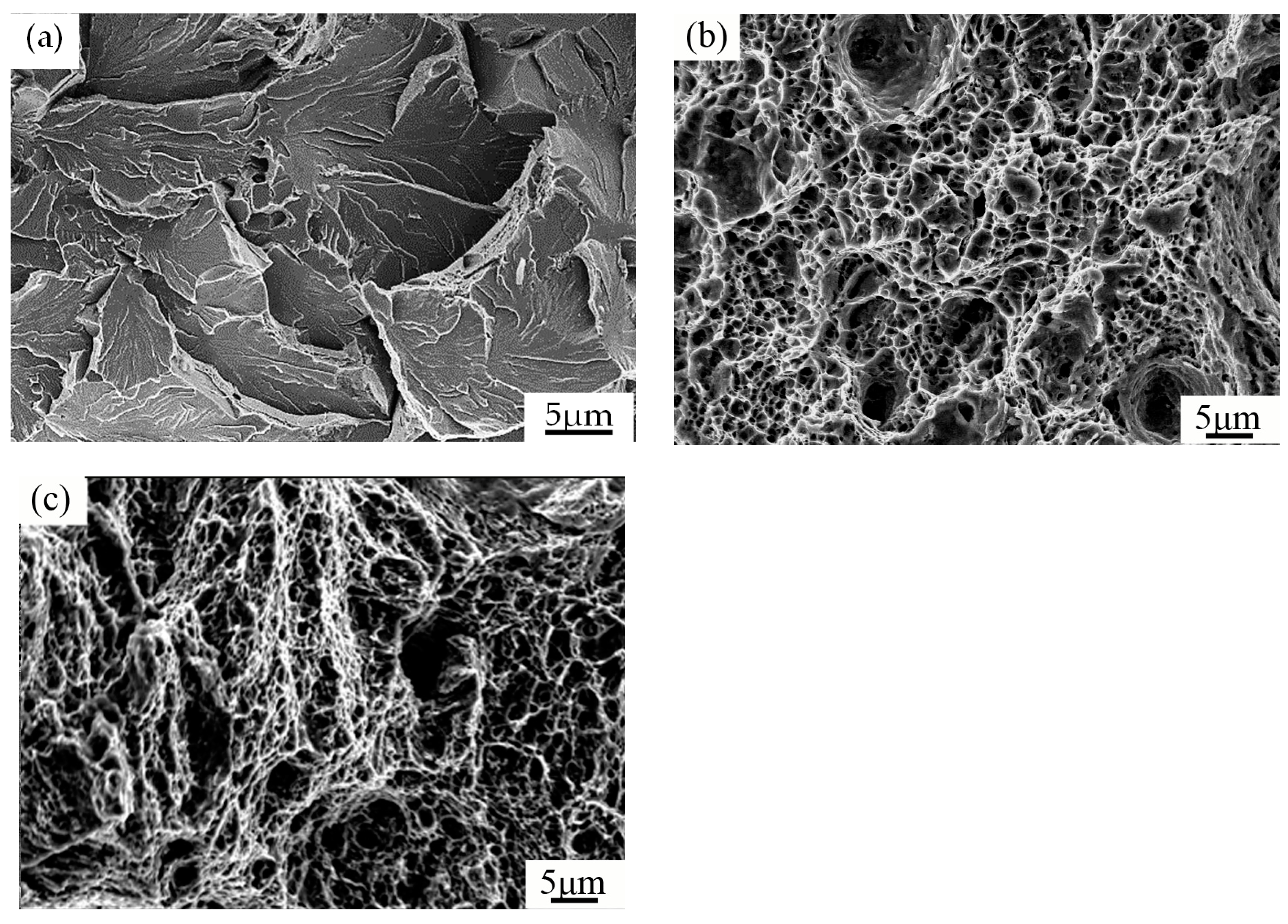
Figure 7.
Curves (da/dN versus ∆K) for three types of casing drilling steels: (a) Fatigue crack growth curves for three types of casing drilling steels; (b) Paris’ law curves for three types of casing drilling steels.
Figure 7.
Curves (da/dN versus ∆K) for three types of casing drilling steels: (a) Fatigue crack growth curves for three types of casing drilling steels; (b) Paris’ law curves for three types of casing drilling steels.

Table 1.
Chemical compositions of different casing drilling steels (wt.%).
| Materials | K55 | N80 | P110 |
|---|---|---|---|
| C | 0.36 | 0.38 | 0.32 |
| Si | 0.32 | 0.23 | 0.23 |
| Mn | 1.51 | 1.38 | 1.47 |
| P | 0.025 | 0.015 | 0.013 |
| S | 0.0085 | 0.0076 | 0.0058 |
| Cr | 0.028 | 0.023 | 0.036 |
| Mo | 0.025 | 0.021 | 0.027 |
| Ni | 0.004 | 0.003 | 0.01 |
| V | 0.006 | 0.006 | 0.089 |
| Ti | 0.004 | 0.003 | 0.003 |
| Cu | 0.007 | 0.007 | 0.045 |
| Fe | Balance | Balance | Balance |
Table 2.
Hardness measurement for the different microstructure steels.
| Materials | Average Brinell Hardness (HB) ± Standard Deviation (S2.5 mm, 1837.5 N, 10 s) | Average Vickers Hardness (HV) ± Standard Deviation (0.49 N, 10 s) |
|---|---|---|
| K55steel | 198 ± 2 | 219 ± 20 |
| N80 steel | 214 ± 8 | 239 ± 31 |
| P110 steel | 273 ± 7 | 297 ± 7 |
Table 3.
Comparison between the mechanical properties of different steels.
| Materials | Yield Strength (MPa) | Tensile Strength (MPa) | Young’s Modulus (GPa) | Strain Hardening Exponent | Impact Energy Value (J) | Reference | ||
|---|---|---|---|---|---|---|---|---|
| σ0.2 | σ0.5 | σ0.6 | ||||||
| K55 | 403 | 414 | / | 708 | 206 | 0.2309 | 14.0 | This work |
| N80 | 559 | 565 | / | 732 | 199 | 0.1438 | 72.0 | This work |
| P110 | 808 | / | 816 | 898 | 191 | 0.0665 | 70.7 | This work |
| MHCS | 390.7 | / | 395.8 | 709 | 190 | / | / | [13] |
| MCS | 654 | / | 697.3 | 786 | 209 | / | / | [13] |
| P110s | / | / | 775 | 835 | / | / | / | [14] |
| K55 | 443.3 | / | / | 738.2 | / | / | / | [9] |
| N80Q | 565 | / | / | 728 | / | / | / | [15] |
Where MHCS indicates medium-high carbon steel, MCS indicates medium carbon steel.
Table 4.
Material constants m and C.
| Materials | K55 | N80 | P110 |
|---|---|---|---|
| Paris constants m | 3.4965 | 3.1162 | 2.7257 |
| Paris constants C (×10−13) | 6.3 | 29.1 | 120.3 |
Disclaimer/Publisher’s Note: The statements, opinions and data contained in all publications are solely those of the individual author(s) and contributor(s) and not of MDPI and/or the editor(s). MDPI and/or the editor(s) disclaim responsibility for any injury to people or property resulting from any ideas, methods, instructions or products referred to in the content. |
© 2023 by the authors. Licensee MDPI, Basel, Switzerland. This article is an open access article distributed under the terms and conditions of the Creative Commons Attribution (CC BY) license (https://creativecommons.org/licenses/by/4.0/).
Share and Cite
MDPI and ACS Style
He, X.; Zhang, M.; Xu, T.; Lei, L.; Li, Y. Evaluation of Mechanical Properties of Different Casing Drilling Steels. Metals 2023, 13, 427. https://doi.org/10.3390/met13020427
AMA Style
He X, Zhang M, Xu T, Lei L, Li Y. Evaluation of Mechanical Properties of Different Casing Drilling Steels. Metals. 2023; 13(2):427. https://doi.org/10.3390/met13020427
Chicago/Turabian StyleHe, Xiaoyu, Min Zhang, Tianhan Xu, Longyu Lei, and Yi Li. 2023. "Evaluation of Mechanical Properties of Different Casing Drilling Steels" Metals 13, no. 2: 427. https://doi.org/10.3390/met13020427
Note that from the first issue of 2016, this journal uses article numbers instead of page numbers. See further details here.